EP4282565A2 - Jigsaw - Google Patents
Jigsaw Download PDFInfo
- Publication number
- EP4282565A2 EP4282565A2 EP23170602.9A EP23170602A EP4282565A2 EP 4282565 A2 EP4282565 A2 EP 4282565A2 EP 23170602 A EP23170602 A EP 23170602A EP 4282565 A2 EP4282565 A2 EP 4282565A2
- Authority
- EP
- European Patent Office
- Prior art keywords
- housing
- jigsaw
- coupled
- output spindle
- motor
- Prior art date
- Legal status (The legal status is an assumption and is not a legal conclusion. Google has not performed a legal analysis and makes no representation as to the accuracy of the status listed.)
- Pending
Links
Images





Classifications
-
- B—PERFORMING OPERATIONS; TRANSPORTING
- B23—MACHINE TOOLS; METAL-WORKING NOT OTHERWISE PROVIDED FOR
- B23D—PLANING; SLOTTING; SHEARING; BROACHING; SAWING; FILING; SCRAPING; LIKE OPERATIONS FOR WORKING METAL BY REMOVING MATERIAL, NOT OTHERWISE PROVIDED FOR
- B23D49/00—Machines or devices for sawing with straight reciprocating saw blades, e.g. hacksaws
- B23D49/10—Hand-held or hand-operated sawing devices with straight saw blades
- B23D49/16—Hand-held or hand-operated sawing devices with straight saw blades actuated by electric or magnetic power or prime movers
- B23D49/162—Pad sawing devices
-
- B—PERFORMING OPERATIONS; TRANSPORTING
- B23—MACHINE TOOLS; METAL-WORKING NOT OTHERWISE PROVIDED FOR
- B23D—PLANING; SLOTTING; SHEARING; BROACHING; SAWING; FILING; SCRAPING; LIKE OPERATIONS FOR WORKING METAL BY REMOVING MATERIAL, NOT OTHERWISE PROVIDED FOR
- B23D51/00—Sawing machines or sawing devices working with straight blades, characterised only by constructional features of particular parts; Carrying or attaching means for tools, covered by this subclass, which are connected to a carrier at both ends
- B23D51/16—Sawing machines or sawing devices working with straight blades, characterised only by constructional features of particular parts; Carrying or attaching means for tools, covered by this subclass, which are connected to a carrier at both ends of drives or feed mechanisms for straight tools, e.g. saw blades, or bows
-
- B—PERFORMING OPERATIONS; TRANSPORTING
- B23—MACHINE TOOLS; METAL-WORKING NOT OTHERWISE PROVIDED FOR
- B23D—PLANING; SLOTTING; SHEARING; BROACHING; SAWING; FILING; SCRAPING; LIKE OPERATIONS FOR WORKING METAL BY REMOVING MATERIAL, NOT OTHERWISE PROVIDED FOR
- B23D49/00—Machines or devices for sawing with straight reciprocating saw blades, e.g. hacksaws
- B23D49/10—Hand-held or hand-operated sawing devices with straight saw blades
- B23D49/16—Hand-held or hand-operated sawing devices with straight saw blades actuated by electric or magnetic power or prime movers
-
- B—PERFORMING OPERATIONS; TRANSPORTING
- B23—MACHINE TOOLS; METAL-WORKING NOT OTHERWISE PROVIDED FOR
- B23D—PLANING; SLOTTING; SHEARING; BROACHING; SAWING; FILING; SCRAPING; LIKE OPERATIONS FOR WORKING METAL BY REMOVING MATERIAL, NOT OTHERWISE PROVIDED FOR
- B23D51/00—Sawing machines or sawing devices working with straight blades, characterised only by constructional features of particular parts; Carrying or attaching means for tools, covered by this subclass, which are connected to a carrier at both ends
-
- B—PERFORMING OPERATIONS; TRANSPORTING
- B23—MACHINE TOOLS; METAL-WORKING NOT OTHERWISE PROVIDED FOR
- B23D—PLANING; SLOTTING; SHEARING; BROACHING; SAWING; FILING; SCRAPING; LIKE OPERATIONS FOR WORKING METAL BY REMOVING MATERIAL, NOT OTHERWISE PROVIDED FOR
- B23D51/00—Sawing machines or sawing devices working with straight blades, characterised only by constructional features of particular parts; Carrying or attaching means for tools, covered by this subclass, which are connected to a carrier at both ends
- B23D51/02—Sawing machines or sawing devices working with straight blades, characterised only by constructional features of particular parts; Carrying or attaching means for tools, covered by this subclass, which are connected to a carrier at both ends of beds; of guiding arrangements for work-tables or saw carriers; of frames
-
- B—PERFORMING OPERATIONS; TRANSPORTING
- B23—MACHINE TOOLS; METAL-WORKING NOT OTHERWISE PROVIDED FOR
- B23D—PLANING; SLOTTING; SHEARING; BROACHING; SAWING; FILING; SCRAPING; LIKE OPERATIONS FOR WORKING METAL BY REMOVING MATERIAL, NOT OTHERWISE PROVIDED FOR
- B23D59/00—Accessories specially designed for sawing machines or sawing devices
- B23D59/006—Accessories specially designed for sawing machines or sawing devices for removing or collecting chips
- B23D59/0062—Accessories specially designed for sawing machines or sawing devices for removing or collecting chips by blowing
-
- B—PERFORMING OPERATIONS; TRANSPORTING
- B25—HAND TOOLS; PORTABLE POWER-DRIVEN TOOLS; MANIPULATORS
- B25F—COMBINATION OR MULTI-PURPOSE TOOLS NOT OTHERWISE PROVIDED FOR; DETAILS OR COMPONENTS OF PORTABLE POWER-DRIVEN TOOLS NOT PARTICULARLY RELATED TO THE OPERATIONS PERFORMED AND NOT OTHERWISE PROVIDED FOR
- B25F5/00—Details or components of portable power-driven tools not particularly related to the operations performed and not otherwise provided for
- B25F5/02—Construction of casings, bodies or handles
Definitions
- the present invention relates to power tools, and more specifically to jigsaws.
- a jigsaw including a housing, a handle extending substantially transverse from the housing in a direction of a handle axis, a battery selectively coupled to the handle, a foot plate coupled to the housing and configured to contact a workpiece during a cutting operation, and a drive assembly powered by the battery.
- the drive assembly includes a motor, a fan, a transmission driven by the motor, and an output spindle driven by the transmission in a reciprocating manner and coupled to a cutting blade.
- the jigsaw further includes a frame supported within the housing which, in turn, supports the motor and the transmission.
- the frame includes a shroud surrounding at least a portion of the fan and an air chute in fluid communication with the shroud that together direct an airflow produced by the fan toward a cutting area adjacent the cutting blade.
- the jigsaw further includes a baffle that is selectively moveable into the air chute to redirect the airflow away from the cutting blade.
- the present invention provides, in another aspect, a jigsaw including a housing, a handle extending substantially transverse from the housing in a direction of a handle axis, a battery selectively coupled to the handle, a foot plate coupled to the housing and configured to contact a workpiece during a cutting operation, and a drive assembly powered by the battery.
- the drive assembly includes a motor, a transmission driven by the motor, an output spindle driven by the transmission and coupled to a cutting blade, and a scotch yoke mechanism to convert a rotational motion of the transmission to a reciprocating motion of the output spindle and the cutting blade within a blade plane.
- the jigsaw further includes a support block that is coupled to the housing and receives the output spindle. The output spindle slides along the support block as the support block inhibits the output spindle from moving in a direction transverse to the blade plane.
- a jigsaw including a housing, a handle extending substantially transverse from the housing in a direction of a handle axis, a battery selectively coupled to the handle, a foot plate coupled to the housing and configured to contact a workpiece during a cutting operation, and a drive assembly powered by the battery.
- the drive assembly includes a motor supported within the housing via a plurality of ribs, a transmission driven by the motor, and an output spindle driven by the transmission and coupled to a cutting blade.
- the jigsaw further includes an activation switch that is slidable along a switch axis that is parallel to the handle axis between an activated state, in which the drive assembly is activated, and a deactivated state, in which the drive assembly is deactivated.
- a linkage is directly coupled to and moveable with the activation switch. The linkage is configured to interact with a limit switch. The linkage slides through at least one of the ribs when the activation switch is moved between the activated state and the deactivated state.
- the present invention provides, in another aspect, a jigsaw comprising:
- the jigsaw may further comprise a dust shield that is removably coupled to the housing for creating a debris chamber about the cutting area, wherein the debris chamber may be enclosed by at least portions of the housing, the foot plate, and the dust shield.
- the foot plate may include a passageway in fluid communication with the cutting area and may be configured to be coupled to a vacuum source, such that the vacuum source may draw dust and debris from the debris chamber via the passageway in the foot plate.
- the fan may create a low-pressure zone within the housing, which draws the airflow through at least one vent in the housing, the motor, and the fan, and wherein the fan may create a high-pressure zone adjacent the cutting blade to disperse dust and debris away from the cutting blade.
- the baffle may be moveable between an open position, in which the airflow is permitted to travel through the air chute and toward the cutting area, and a closed position, in which the baffle inhibits the airflow from traveling toward the cutting area and instead redirects the airflow out of the housing away from the cutting blade.
- the jigsaw may further comprise a switch coupled to the baffle, wherein manual actuation of the switch moves the baffle between the open position and the closed position.
- the jigsaw may further comprise an air guide disposed between the air chute and the cutting area, wherein the air guide may be configured to direct the airflow towards the cutting area
- the air guide may be removably coupled to the frame.
- the air guide may be integrally formed with the frame.
- the jigsaw may further comprise a linkage operable to selectively impart an orbit motion to the cutting blade, wherein the air guide may be integrally formed with the linkage.
- the present invention provides, in another aspect, a jigsaw comprising:
- the support block may mechanically interferes with the output spindle in a direction transverse to the blade plane to maintain alignment of the output spindle with the blade plane.
- the support block may define an elongated aperture through which the output spindle is received.
- the output spindle may have a pair of outer wall surfaces that mate with and slide along a pair of inner wall surfaces of the elongated aperture.
- the elongated aperture may enable the output spindle to translate through a length of the elongated aperture and within the blade plane, in which the elongated aperture inhibits movement of the output spindle in a direction transverse to the blade plane.
- the jigsaw may further comprise an O-ring disposed around the output spindle to inhibit dust and debris from entering the housing.
- the present invention provides, in another aspect, a jigsaw comprising:
- the linkage and the activation switch may be disposed radially outward relative to the motor.
- the linkage may be parallel to the handle axis.
- the linkage may be disposed rearward of the motor.
- FIG. 1 illustrates a power tool, such as a jigsaw 10, including a housing 14, a handle 18 extending from the housing 14 in a generally transverse direction, a battery 22 removably coupled to the handle 18, a foot plate 26 pivotably coupled to the housing 14 and configured to contact a workpiece during a cutting operation, and a cutting blade 30 protruding from the housing 14 and the lower surface of the foot plate 26.
- the jigsaw 10 includes a drive assembly 34 ( FIG. 2 ) powered by the battery 22 and operable to impart reciprocating motion to the cutting blade 30 for cutting of a workpiece.
- the jigsaw 10 defines a handle axis 38 extending in the direction of the handle 18.
- the cutting blade 30 generally reciprocates within a blade plane 40 during a cutting operation.
- the handle 18 receives the battery 22 along the handle axis 38 and supports a controller 46.
- the controller 46 is disposed between the battery 22 and the drive assembly 34 in a direction along the handle axis 38.
- the jigsaw 10 also includes gripping surfaces 42a, 42b disposed on the housing 14 and the handle 18, respectively, that are graspable by a user to operate and maneuver the jigsaw 10 relative to a workpiece.
- the gripping surfaces 42a, 42b in addition to the housing 14 and the handle 18, are composed of a non-conductive material (e.g., plastic with or without an elastomeric overmold). Such a non-conductive material electrically insulates the user should the user inadvertently cut an electrical wire during a cutting operation, thus inhibiting, or at least mitigating, an electrical shock.
- the jigsaw 10 further includes an activation switch 54 in electrical communication with the controller 46 to selectively supply power to the drive assembly 34.
- the activation switch 54 provides an input to the controller 46 which, in turn, instructs the battery 22 to supply power to the drive assembly 34.
- the activation switch 54 is provided adjacent the handle 18 and disposed radially outward from a brushless direct current (DC) electric motor 66, which is a component of the drive assembly 34 ( FIG. 2 ).
- the activation switch 54 is slidable between an activated state, in which the battery 22 supplies power to the drive assembly 34, and a deactivated state, in which the drive assembly 34 is deactivated.
- the activation switch 54 is slidable along a switch axis 56 that is parallel to the handle axis 38 of the jigsaw 10 ( FIG. 1 ).
- the activation switch 54 is coupled to a linkage 58 that is disposed on the interior of the housing 14 and is moveable with the activation switch 54 ( FIG. 3 ).
- the linkage 58 is parallel to the handle axis 38 as well.
- the linkage 58 is configured to interact with a limit switch 60 that is disposed rearward of the motor 66 and selectively depress an arm 61 of the limit switch 60 for activating the motor 66.
- the limit switch 60 is in electrical communication with the controller 46.
- the linkage 58 is also disposed radially outward from the motor 66 relative to the handle axis 38.
- the linkage 58 extends through a plurality of ribs 62 on the interior of the housing 14 that support the motor 66 in the housing 14. As such, the linkage 58 slides through aligned slots 64 in the ribs 62 as the linkage 58 engages and disengages the limit switch 60 during the activated state and the deactivated state, respectively.
- the drive assembly 34 of the jigsaw 10 is disposed within the housing 14 and the handle 18.
- the drive assembly 34 includes the motor 66, a transmission 70 driven by the motor 66, an output spindle 72 to which the cutting blade 30 is removably secured, and a scotch yoke mechanism 94 that transfers the rotational motion of the transmission 70 to a reciprocating motion of the output spindle 72.
- a frame 74 is disposed within the housing 14 and supports the motor 66 and the transmission 70 within the housing 14.
- the frame 74 is composed of a non-conductive material (e.g., plastic) like the housing 14 and the handle 18.
- the frame 74 includes two apertures 78, 82 that support the motor 66 and the transmission 70, respectively.
- the aperture 78 receives and supports a drive shaft 84 of the motor 66 which, in turn, supports a helical drive gear 86 ( FIG. 4 ).
- the aperture 82 receives and supports a driven shaft 88 of a helical driven gear 90 of the transmission 70.
- the helical drive gear 86 intermeshes and drives the helical driven gear 90 of the transmission 70. Due to the rotational motion of the transmission 70 being converted to the reciprocating motion of the output spindle 72 via the scotch yoke mechanism 94, the cutting blade 30 is also driven in a reciprocating manner.
- the frame 74 also includes a shroud 98 and an air chute 100 that is in fluid communication with the shroud 98.
- the shroud 98, the air chute 100, and a fan 102 disposed within the shroud 98 ( FIG. 3 ) and coupled to the drive shaft 84 of the motor 66 cooperate to direct an airflow A from the fan 102 toward a cutting area 103 adjacent to the cutting blade 30 and the foot plate 26.
- the fan 102 when driven by the motor 66, creates a low-pressure zone within the housing 14, thereby drawing the airflow A through a plurality of intake vents 104 in the housing 14 ( FIGS. 1 and 2 ) and through the motor 66.
- a baffle 105 is movably disposed within the air chute 100 between a closed position and an open position. In the closed position ( FIG. 6 ), the baffle 105 is disposed within the air chute 100, such that the airflow A is redirected from the air chute 100 and discharged through an air discharge port 106 of the housing 14 away from the cutting blade 30. In the open position ( FIG. 7 ), the baffle 105 is removed from the air chute 100, such that the airflow A continues through the air chute 100 and toward the cutting blade 30.
- the baffle 105 translates between the open and closed positions via manual actuation of a blower switch 112 ( FIGS. 2 and 5 ).
- the blower switch 112 is directly coupled to the baffle 105 and moves along a direction parallel to the handle axis 38.
- the baffle 105 also moves between the open and closed position along a direction parallel to the handle axis 38.
- FIG. 10 illustrates another embodiment of a jigsaw 500 (with like reference numerals being used for like features as the jigsaw 10) further including an air guide 113 coupled to the frame 74 to redirect the airflow A downward and towards a roller 115 supporting the cutting blade 30.
- the roller 115 is supported upon a linkage 117 operable to selectively impart an orbit motion to the cutting blade 30 during a return (i.e., cutting) stroke of the cutting blade 30.
- the airflow A is directed past the cutting blade 30 and in close proximity to the underlying workpiece being cut, effectively clearing dust and debris away from the cutting blade 30 and the region on the workpiece being cut.
- the air guide 113 is coupled to the frame 74 by a snap-fit mechanism. However, in other embodiments, the air guide 113 may be fastened to the frame 74 or integrally formed therewith.
- FIG. 12 illustrates another embodiment of a jigsaw 1000 (with like reference numerals being used for like features as the jigsaw 10) including an air guide 1113 that is integrally formed as a single piece with the linkage 117 ( FIG. 12 ).
- the air guide 1113 is operable to direct the airflow A past the cutting blade 30 and in close proximity to the underlying workpiece being cut, effectively clearing dust and debris away from the cutting blade 30 and the region on the workpiece being cut.
- the jigsaw 10 further includes a dust shield 108 ( FIG. 1 ) that is removably coupled between the housing 14 and the foot plate 26.
- a debris chamber 110 is created when the dust shield 108 is coupled to the housing 14, which is defined as the enclosed space immediately surrounding the cutting blade 30 by at least portions of the housing 14, the foot plate 26, and the dust shield 108.
- the airflow A is directed to the debris chamber 110.
- the dust shield 108 inhibits dust and debris from leaving the debris chamber 110, at which point a vacuum source 116 (as also shown in FIG. 7 ) may draw the dust and debris from the debris chamber 110.
- the debris chamber 110 is in fluid communication with a passageway 114 extending through the foot plate 26, which is ultimately in fluid communication with the vacuum source 116 via a vacuum adapter 118 coupled to the passageway 114.
- the vacuum source 116 generates a low-pressure zone within the debris chamber 110 to draw dust and debris out of the debris chamber 110 along an airflow B. Specifically, dust and debris within the debris chamber 110 travel through the passageway 114 and the vacuum adapter 118 before reaching the vacuum source 116.
- the baffle 105 may be positioned in the closed position to prevent the airflow A from merging with the airflow B.
- the dust shield 108 is composed of a transparent material, so that a user can view the cutting blade 30 and the workpiece during a cutting operation. Containing dust and debris within the debris chamber 110 and extracting it therefrom helps to maintain a clean workstation and provides a clear view of the workpiece.
- the airflow A is exhausted to create a high-pressure zone adjacent the cutting blade 30, where the airflow A disperses dust and debris away from the cutting blade 30. This ensures a user has a clear view of a workpiece during a cutting operation.
- the vacuum 116 can generate the low-pressure zone within the cutting area 103 adjacent to the cutting blade 30 to draw dust and debris out of the cutting area 103 along the airflow B.
- the drive assembly 34 is configured in a manner to increase cutting accuracy during a cutting operation.
- the output spindle 72 is supported within the housing 14 via a support block 120, as shown in FIG. 8 .
- An elongated aperture 122 ( FIG. 9 ) of the support block 120 receives the output spindle 72 and helps maintain alignment of the output spindle 72 within the blade plane 40 as the output spindle 72 reciprocates. More specifically, the support block 120 mechanically interferes with the output spindle 72 in a direction transverse to the blade plane 40 to maintain alignment of the output spindle 72 with the blade plane 40.
- the elongated aperture 122 includes a pair of flat inner wall surfaces 124 that abut a pair of corresponding flat outer wall surfaces 125 of the output spindle 72 to inhibit the output spindle 72 from oscillating out of the blade plane 40.
- the flat outer wall surfaces 125 of the output spindle 72 slide against the flat inner wall surfaces 124 of the support block 120. Effectively, the blade plane 40 bisects the output spindle 72 (as shown in FIG. 9 ), and the elongated aperture 122 cooperates with the output spindle 72 to maintain the blade plane 40 alignment along a centerline of the output spindle 72.
- the elongated aperture 122 does, however, enable the output spindle 72 to reciprocate through a length of the elongated aperture 122 when the jigsaw 10 is in an orbital cutting mode rather than a straight cutting mode.
- the jigsaw 10 includes a mode selector switch 128 ( FIG. 1 ) that allows a user to switch the jigsaw 10 between the orbital cutting mode and the straight cutting mode.
- the jigsaw 10 further includes a quick-disconnect mechanism or a blade ejection mechanism 126 disposed on the housing 14.
- the blade ejection mechanism 126 is pivotable about output spindle 72 and is configured to selectively lock the cutting blade 30 to the output spindle 72.
- the blade ejection mechanism 126 is pivotable from a locked position, in which the cutting blade 30 is inhibited from being removed from the output spindle 72, and an unlocked position, in which the cutting blade 30 is permitted to be removed from the output spindle 72.
- FIG. 1 illustrates the blade ejection mechanism 126 is biased toward the locked position.
- An O-ring 129 is disposed between sealing plates 130 of the output spindle 72 ( FIG. 4 ). Furthermore, the O-ring 129 is fit snuggly around the output spindle 72 to inhibit dust and debris from inadvertently entering the housing 14 through the blade ejection mechanism 126.
- the jigsaw 10 further includes a work light 132 that is automatically turned on when the activation switch 54 is actuated to activate the motor 66.
- a work light button 134 is provided on the housing 14 to optionally deactivate the work light 132 such that actuating the activation switch 54 no longer automatically turns on the work light 132.
- a user may desire to deactivate the work light 132 via the work light button 134, for example, when a user is performing an inverted cutting operation so the work light 132 does not shine in the eyes of a user.
- a user may grasp the gripping surfaces 42a, 42b of the housing 14 and the handle 18 to maneuver the jigsaw 10 relative to a workpiece.
- the user may rest the jigsaw 10 on the workpiece via the foot plate 26 and align the cutting blade 30 with the desired cut.
- the cutting blade 30 reciprocates within the blade plane 40 in response to the user sliding the activation switch 54 into the activated state. Specifically, the user slides the activation switch 54 along the switch axis 56 from the non-activated state to the activated state, causing the motor 66 to drive the transmission 70 and reciprocate the cutting blade 30.
- the work light 132 automatically illuminates the workpiece unless the work light button 134 has been depressed.
- the fan 102 rotates with the motor 66, thereby generating the airflow A that travels into the housing 14 via the plurality of vents 104, and through the motor 66, the shroud 98, and the air chute 100. If the blower switch 112 holds the baffle 105 in the open position, then the airflow A continues through the air chute 100 toward the cutting blade 30. If the blower switch 112 holds the baffle 105 in the closed position, then the airflow A is discharged from the housing 14 via the air discharge port 106.
Landscapes
- Engineering & Computer Science (AREA)
- Mechanical Engineering (AREA)
- Sawing (AREA)
Abstract
Description
- This application claims priority to co-pending
U.S. Provisional Patent Application No. 63/384,475, filed November 21, 2022 U.S. Provisional Patent Application No. 63/338,288, filed May 4, 2022 - The present invention relates to power tools, and more specifically to jigsaws.
- Various power tools, such as jigsaws, create dust and debris during a cutting operation. Not only can dust and debris be hazardous at some workstations, but dust and debris can accumulate on the workpiece itself making it difficult to view the workpiece during the cutting operation.
- The present invention provides, in one aspect, a jigsaw including a housing, a handle extending substantially transverse from the housing in a direction of a handle axis, a battery selectively coupled to the handle, a foot plate coupled to the housing and configured to contact a workpiece during a cutting operation, and a drive assembly powered by the battery. The drive assembly includes a motor, a fan, a transmission driven by the motor, and an output spindle driven by the transmission in a reciprocating manner and coupled to a cutting blade. The jigsaw further includes a frame supported within the housing which, in turn, supports the motor and the transmission. The frame includes a shroud surrounding at least a portion of the fan and an air chute in fluid communication with the shroud that together direct an airflow produced by the fan toward a cutting area adjacent the cutting blade. The jigsaw further includes a baffle that is selectively moveable into the air chute to redirect the airflow away from the cutting blade.
- The present invention provides, in another aspect, a jigsaw including a housing, a handle extending substantially transverse from the housing in a direction of a handle axis, a battery selectively coupled to the handle, a foot plate coupled to the housing and configured to contact a workpiece during a cutting operation, and a drive assembly powered by the battery. The drive assembly includes a motor, a transmission driven by the motor, an output spindle driven by the transmission and coupled to a cutting blade, and a scotch yoke mechanism to convert a rotational motion of the transmission to a reciprocating motion of the output spindle and the cutting blade within a blade plane. The jigsaw further includes a support block that is coupled to the housing and receives the output spindle. The output spindle slides along the support block as the support block inhibits the output spindle from moving in a direction transverse to the blade plane.
- The present invention provides, in yet another aspect, a jigsaw including a housing, a handle extending substantially transverse from the housing in a direction of a handle axis, a battery selectively coupled to the handle, a foot plate coupled to the housing and configured to contact a workpiece during a cutting operation, and a drive assembly powered by the battery. The drive assembly includes a motor supported within the housing via a plurality of ribs, a transmission driven by the motor, and an output spindle driven by the transmission and coupled to a cutting blade. The jigsaw further includes an activation switch that is slidable along a switch axis that is parallel to the handle axis between an activated state, in which the drive assembly is activated, and a deactivated state, in which the drive assembly is deactivated. A linkage is directly coupled to and moveable with the activation switch. The linkage is configured to interact with a limit switch. The linkage slides through at least one of the ribs when the activation switch is moved between the activated state and the deactivated state.
- The present invention provides, in another aspect, a jigsaw comprising:
- a housing;
- a handle extending substantially transverse from the housing in a direction of a handle axis;
- a battery selectively coupled to the handle;
- a foot plate coupled to the housing and configured to contact a workpiece during a cutting operation;
- a drive assembly powered by the battery, the drive assembly including
- a motor,
- a fan,
- a transmission driven by the motor, and
- an output spindle driven by the transmission in a reciprocating manner and coupled to a cutting blade;
- a frame supported within the housing which, in turn, supports the motor and the transmission, the frame includes a shroud surrounding at least a portion of the fan and an air chute in fluid communication with the shroud that together direct an airflow produced by the fan toward a cutting area adjacent the cutting blade; and
- a baffle that is selectively moveable into the air chute to redirect the airflow away from the cutting blade.
- The jigsaw may further comprise a dust shield that is removably coupled to the housing for creating a debris chamber about the cutting area, wherein the debris chamber may be enclosed by at least portions of the housing, the foot plate, and the dust shield.
- The foot plate may include a passageway in fluid communication with the cutting area and may be configured to be coupled to a vacuum source, such that the vacuum source may draw dust and debris from the debris chamber via the passageway in the foot plate.
- The fan may create a low-pressure zone within the housing, which draws the airflow through at least one vent in the housing, the motor, and the fan, and wherein the fan may create a high-pressure zone adjacent the cutting blade to disperse dust and debris away from the cutting blade.
- The baffle may be moveable between an open position, in which the airflow is permitted to travel through the air chute and toward the cutting area, and a closed position, in which the baffle inhibits the airflow from traveling toward the cutting area and instead redirects the airflow out of the housing away from the cutting blade.
- The jigsaw may further comprise a switch coupled to the baffle, wherein manual actuation of the switch moves the baffle between the open position and the closed position.
- The jigsaw may further comprise an air guide disposed between the air chute and the cutting area, wherein the air guide may be configured to direct the airflow towards the cutting area
- The air guide may be removably coupled to the frame.
- The air guide may be integrally formed with the frame.
- The jigsaw may further comprise a linkage operable to selectively impart an orbit motion to the cutting blade, wherein the air guide may be integrally formed with the linkage.
- The present invention provides, in another aspect, a jigsaw comprising:
- a housing;
- a handle extending substantially transverse from the housing in a direction of a handle axis,
- a battery selectively coupled to the handle;
- a foot plate coupled to the housing and configured to contact a workpiece during a cutting operation;
- a drive assembly powered by the battery, the drive assembly including
- a motor,
- a transmission driven by the motor,
- an output spindle driven by the transmission and coupled to a cutting blade, and
- a scotch yoke mechanism to convert a rotational motion of the transmission to a reciprocating motion of the output spindle and the cutting blade within a blade plane; and
- a support block that is coupled to the housing and receives the output spindle, wherein the output spindle slides along the support block as the support block inhibits the output spindle from moving in a direction transverse to the blade plane.
- The support block may mechanically interferes with the output spindle in a direction transverse to the blade plane to maintain alignment of the output spindle with the blade plane.
- The support block may define an elongated aperture through which the output spindle is received.
- The output spindle may have a pair of outer wall surfaces that mate with and slide along a pair of inner wall surfaces of the elongated aperture.
- The elongated aperture may enable the output spindle to translate through a length of the elongated aperture and within the blade plane, in which the elongated aperture inhibits movement of the output spindle in a direction transverse to the blade plane.
- The jigsaw may further comprise an O-ring disposed around the output spindle to inhibit dust and debris from entering the housing.
- The present invention provides, in another aspect, a jigsaw comprising:
- a housing;
- a handle extending substantially transverse from the housing in a direction of a handle axis;
- a battery selectively coupled to the handle;
- a foot plate coupled to the housing and configured to contact a workpiece during a cutting operation;
- a drive assembly powered by the battery, the drive assembly including
- a motor supported within the housing via a plurality of ribs,
- a transmission driven by the motor, and
- an output spindle driven by the transmission and coupled to a cutting blade;
- an activation switch that is slidable along a switch axis that is parallel to the handle axis between an activated state, in which the drive assembly is activated, and a deactivated state, in which the drive assembly is deactivated; and
- a linkage directly coupled to and moveable with the activation switch, the linkage is configured to interact with a limit switch,
- wherein the linkage slides through at least one of the ribs when the activation switch is moved between the activated state and the deactivated state.
- The linkage and the activation switch may be disposed radially outward relative to the motor.
- The linkage may be parallel to the handle axis.
- The linkage may be disposed rearward of the motor.
- Other features and aspects of the invention will become apparent by consideration of the following detailed description and accompanying drawings.
-
-
FIG. 1 is perspective view of a jigsaw in accordance with an embodiment of the invention. -
FIG. 2 is a partially exploded perspective view of the jigsaw ofFIG. 1 . -
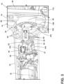
FIG. 3 is an enlarged perspective view of the jigsaw ofFIG. 1 , with a portion of the housing removed. -
FIG. 4 is a perspective view of a portion of a drive assembly of the jigsaw ofFIG. 1 , illustrating a motor, a transmission, and a frame supporting the motor and transmission. -
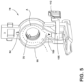
FIG. 5 is a perspective view of the frame of the drive assembly ofFIG. 4 . -
FIG. 6 is a cross-sectional view of the jigsaw taken along line 6-6 ofFIG. 2 , illustrating a baffle in a closed position. -
FIG. 7 is another cross-sectional view of the jigsaw ofFIG. 6 , illustrating the baffle in an open position. -
FIG. 8 is a perspective view of a portion of the drive assembly of the jigsaw ofFIG. 1 . -
FIG. 9 is a cross-sectional view of a portion of the drive assembly taken along line 9-9 ofFIG. 8 . -
FIG. 10 is a jigsaw, with portions removed, in accordance with another embodiment of the invention. -
FIG. 11 is an enlarged perspective view of the jigsaw ofFIG. 10 , illustrating an air guide coupled to the frame. -
FIG. 12 is an enlarged plan view of a jigsaw in accordance with yet another embodiment of the invention. - Before any embodiments of the invention are explained in detail, it is to be understood that the invention is not limited in its application to the details of construction and the arrangement of components set forth in the following description or illustrated in the following drawings. The invention is capable of other embodiments and of being practiced or of being carried out in various ways. Also, it is to be understood that the phraseology and terminology used herein is for the purpose of description and should not be regarded as limiting.
-
FIG. 1 illustrates a power tool, such as ajigsaw 10, including ahousing 14, ahandle 18 extending from thehousing 14 in a generally transverse direction, abattery 22 removably coupled to thehandle 18, afoot plate 26 pivotably coupled to thehousing 14 and configured to contact a workpiece during a cutting operation, and acutting blade 30 protruding from thehousing 14 and the lower surface of thefoot plate 26. Thejigsaw 10 includes a drive assembly 34 (FIG. 2 ) powered by thebattery 22 and operable to impart reciprocating motion to thecutting blade 30 for cutting of a workpiece. Thejigsaw 10 defines ahandle axis 38 extending in the direction of thehandle 18. Moreover, thecutting blade 30 generally reciprocates within ablade plane 40 during a cutting operation. - With reference to
FIGS. 1 and2 , thehandle 18 receives thebattery 22 along thehandle axis 38 and supports acontroller 46. Thecontroller 46 is disposed between thebattery 22 and thedrive assembly 34 in a direction along thehandle axis 38. Thejigsaw 10 also includesgripping surfaces housing 14 and thehandle 18, respectively, that are graspable by a user to operate and maneuver thejigsaw 10 relative to a workpiece. Thegripping surfaces housing 14 and thehandle 18, are composed of a non-conductive material (e.g., plastic with or without an elastomeric overmold). Such a non-conductive material electrically insulates the user should the user inadvertently cut an electrical wire during a cutting operation, thus inhibiting, or at least mitigating, an electrical shock. - With reference to
FIGS. 1-3 , thejigsaw 10 further includes anactivation switch 54 in electrical communication with thecontroller 46 to selectively supply power to thedrive assembly 34. Specifically, theactivation switch 54 provides an input to thecontroller 46 which, in turn, instructs thebattery 22 to supply power to thedrive assembly 34. Theactivation switch 54 is provided adjacent thehandle 18 and disposed radially outward from a brushless direct current (DC)electric motor 66, which is a component of the drive assembly 34 (FIG. 2 ). Theactivation switch 54 is slidable between an activated state, in which thebattery 22 supplies power to thedrive assembly 34, and a deactivated state, in which thedrive assembly 34 is deactivated. Theactivation switch 54 is slidable along aswitch axis 56 that is parallel to thehandle axis 38 of the jigsaw 10 (FIG. 1 ). Theactivation switch 54 is coupled to alinkage 58 that is disposed on the interior of thehousing 14 and is moveable with the activation switch 54 (FIG. 3 ). Thelinkage 58 is parallel to thehandle axis 38 as well. Thelinkage 58 is configured to interact with alimit switch 60 that is disposed rearward of themotor 66 and selectively depress anarm 61 of thelimit switch 60 for activating themotor 66. Thelimit switch 60 is in electrical communication with thecontroller 46. Thelinkage 58 is also disposed radially outward from themotor 66 relative to thehandle axis 38. In order for theactivation switch 54 and thelinkage 58 to be disposed radially outward from themotor 66, thelinkage 58 extends through a plurality ofribs 62 on the interior of thehousing 14 that support themotor 66 in thehousing 14. As such, thelinkage 58 slides through alignedslots 64 in theribs 62 as thelinkage 58 engages and disengages thelimit switch 60 during the activated state and the deactivated state, respectively. - With reference to
FIGS. 4 and5 , thedrive assembly 34 of thejigsaw 10 is disposed within thehousing 14 and thehandle 18. Thedrive assembly 34 includes themotor 66, atransmission 70 driven by themotor 66, anoutput spindle 72 to which thecutting blade 30 is removably secured, and ascotch yoke mechanism 94 that transfers the rotational motion of thetransmission 70 to a reciprocating motion of theoutput spindle 72. Aframe 74 is disposed within thehousing 14 and supports themotor 66 and thetransmission 70 within thehousing 14. Theframe 74 is composed of a non-conductive material (e.g., plastic) like thehousing 14 and thehandle 18. Such a non-conductive material electrically insulates the user should the user inadvertently cut an electrical wire during a cutting operation, thus inhibiting, or at least mitigating, an electrical shock. As shown inFIG. 5 , theframe 74 includes twoapertures motor 66 and thetransmission 70, respectively. Theaperture 78 receives and supports adrive shaft 84 of themotor 66 which, in turn, supports a helical drive gear 86 (FIG. 4 ). Theaperture 82 receives and supports a drivenshaft 88 of a helical drivengear 90 of thetransmission 70. Thehelical drive gear 86 intermeshes and drives the helical drivengear 90 of thetransmission 70. Due to the rotational motion of thetransmission 70 being converted to the reciprocating motion of theoutput spindle 72 via thescotch yoke mechanism 94, thecutting blade 30 is also driven in a reciprocating manner. - With reference to
FIG. 5 , theframe 74 also includes ashroud 98 and anair chute 100 that is in fluid communication with theshroud 98. Theshroud 98, theair chute 100, and afan 102 disposed within the shroud 98 (FIG. 3 ) and coupled to thedrive shaft 84 of themotor 66 cooperate to direct an airflow A from thefan 102 toward acutting area 103 adjacent to thecutting blade 30 and thefoot plate 26. Specifically, thefan 102, when driven by themotor 66, creates a low-pressure zone within thehousing 14, thereby drawing the airflow A through a plurality ofintake vents 104 in the housing 14 (FIGS. 1 and2 ) and through themotor 66. The airflow A is then circulated through theshroud 98 via thefan 102 and radially discharged through theair chute 100. Abaffle 105 is movably disposed within theair chute 100 between a closed position and an open position. In the closed position (FIG. 6 ), thebaffle 105 is disposed within theair chute 100, such that the airflow A is redirected from theair chute 100 and discharged through anair discharge port 106 of thehousing 14 away from thecutting blade 30. In the open position (FIG. 7 ), thebaffle 105 is removed from theair chute 100, such that the airflow A continues through theair chute 100 and toward thecutting blade 30. Thebaffle 105 translates between the open and closed positions via manual actuation of a blower switch 112 (FIGS. 2 and5 ). Theblower switch 112 is directly coupled to thebaffle 105 and moves along a direction parallel to thehandle axis 38. Thebaffle 105 also moves between the open and closed position along a direction parallel to thehandle axis 38. -
FIG. 10 illustrates another embodiment of a jigsaw 500 (with like reference numerals being used for like features as the jigsaw 10) further including anair guide 113 coupled to theframe 74 to redirect the airflow A downward and towards aroller 115 supporting thecutting blade 30. Theroller 115 is supported upon alinkage 117 operable to selectively impart an orbit motion to thecutting blade 30 during a return (i.e., cutting) stroke of thecutting blade 30. As a result, the airflow A is directed past thecutting blade 30 and in close proximity to the underlying workpiece being cut, effectively clearing dust and debris away from thecutting blade 30 and the region on the workpiece being cut. As shown inFIG. 11 , theair guide 113 is coupled to theframe 74 by a snap-fit mechanism. However, in other embodiments, theair guide 113 may be fastened to theframe 74 or integrally formed therewith. -
FIG. 12 illustrates another embodiment of a jigsaw 1000 (with like reference numerals being used for like features as the jigsaw 10) including anair guide 1113 that is integrally formed as a single piece with the linkage 117 (FIG. 12 ). Like theair guide 113, theair guide 1113 is operable to direct the airflow A past thecutting blade 30 and in close proximity to the underlying workpiece being cut, effectively clearing dust and debris away from thecutting blade 30 and the region on the workpiece being cut. - The
jigsaw 10 further includes a dust shield 108 (FIG. 1 ) that is removably coupled between thehousing 14 and thefoot plate 26. Adebris chamber 110 is created when thedust shield 108 is coupled to thehousing 14, which is defined as the enclosed space immediately surrounding thecutting blade 30 by at least portions of thehousing 14, thefoot plate 26, and thedust shield 108. When thebaffle 105 is in the open position and thedust shield 108 is coupled to the housing 14 (as shown inFIG. 7 ), the airflow A is directed to thedebris chamber 110. Now, thedust shield 108 inhibits dust and debris from leaving thedebris chamber 110, at which point a vacuum source 116 (as also shown inFIG. 7 ) may draw the dust and debris from thedebris chamber 110. - With reference to
FIGS. 6 and7 , thedebris chamber 110 is in fluid communication with apassageway 114 extending through thefoot plate 26, which is ultimately in fluid communication with thevacuum source 116 via avacuum adapter 118 coupled to thepassageway 114. Thevacuum source 116 generates a low-pressure zone within thedebris chamber 110 to draw dust and debris out of thedebris chamber 110 along an airflow B. Specifically, dust and debris within thedebris chamber 110 travel through thepassageway 114 and thevacuum adapter 118 before reaching thevacuum source 116. When thevacuum source 116 is activated, thebaffle 105 may be positioned in the closed position to prevent the airflow A from merging with the airflow B. Thedust shield 108 is composed of a transparent material, so that a user can view thecutting blade 30 and the workpiece during a cutting operation. Containing dust and debris within thedebris chamber 110 and extracting it therefrom helps to maintain a clean workstation and provides a clear view of the workpiece. In a situation where thedust shield 108 is not coupled to thehousing 14, the airflow A is exhausted to create a high-pressure zone adjacent thecutting blade 30, where the airflow A disperses dust and debris away from thecutting blade 30. This ensures a user has a clear view of a workpiece during a cutting operation. In another situation where thedust shield 108 is not coupled to thehousing 14, thevacuum 116 can generate the low-pressure zone within the cuttingarea 103 adjacent to thecutting blade 30 to draw dust and debris out of thecutting area 103 along the airflow B. - With reference to
FIGS. 8 and 9 , thedrive assembly 34 is configured in a manner to increase cutting accuracy during a cutting operation. Specifically, theoutput spindle 72 is supported within thehousing 14 via asupport block 120, as shown inFIG. 8 . An elongated aperture 122 (FIG. 9 ) of thesupport block 120 receives theoutput spindle 72 and helps maintain alignment of theoutput spindle 72 within theblade plane 40 as theoutput spindle 72 reciprocates. More specifically, thesupport block 120 mechanically interferes with theoutput spindle 72 in a direction transverse to theblade plane 40 to maintain alignment of theoutput spindle 72 with theblade plane 40. Theelongated aperture 122 includes a pair of flat inner wall surfaces 124 that abut a pair of corresponding flat outer wall surfaces 125 of theoutput spindle 72 to inhibit theoutput spindle 72 from oscillating out of theblade plane 40. When theoutput spindle 72 reciprocates, the flat outer wall surfaces 125 of theoutput spindle 72 slide against the flat inner wall surfaces 124 of thesupport block 120. Effectively, theblade plane 40 bisects the output spindle 72 (as shown inFIG. 9 ), and theelongated aperture 122 cooperates with theoutput spindle 72 to maintain theblade plane 40 alignment along a centerline of theoutput spindle 72. Theelongated aperture 122 does, however, enable theoutput spindle 72 to reciprocate through a length of theelongated aperture 122 when thejigsaw 10 is in an orbital cutting mode rather than a straight cutting mode. - The
jigsaw 10 includes a mode selector switch 128 (FIG. 1 ) that allows a user to switch thejigsaw 10 between the orbital cutting mode and the straight cutting mode. - With reference to
FIG. 1 , thejigsaw 10 further includes a quick-disconnect mechanism or ablade ejection mechanism 126 disposed on thehousing 14. Theblade ejection mechanism 126 is pivotable aboutoutput spindle 72 and is configured to selectively lock thecutting blade 30 to theoutput spindle 72. Specifically, theblade ejection mechanism 126 is pivotable from a locked position, in which thecutting blade 30 is inhibited from being removed from theoutput spindle 72, and an unlocked position, in which thecutting blade 30 is permitted to be removed from theoutput spindle 72.FIG. 1 illustrates theblade ejection mechanism 126 is biased toward the locked position. An O-ring 129 is disposed between sealingplates 130 of the output spindle 72 (FIG. 4 ). Furthermore, the O-ring 129 is fit snuggly around theoutput spindle 72 to inhibit dust and debris from inadvertently entering thehousing 14 through theblade ejection mechanism 126. - With reference to
FIGS. 2 and6 , thejigsaw 10 further includes awork light 132 that is automatically turned on when theactivation switch 54 is actuated to activate themotor 66. Awork light button 134 is provided on thehousing 14 to optionally deactivate thework light 132 such that actuating theactivation switch 54 no longer automatically turns on thework light 132. A user may desire to deactivate thework light 132 via thework light button 134, for example, when a user is performing an inverted cutting operation so thework light 132 does not shine in the eyes of a user. - During operation, a user may grasp the
gripping surfaces housing 14 and thehandle 18 to maneuver thejigsaw 10 relative to a workpiece. The user may rest thejigsaw 10 on the workpiece via thefoot plate 26 and align thecutting blade 30 with the desired cut. Thecutting blade 30 reciprocates within theblade plane 40 in response to the user sliding theactivation switch 54 into the activated state. Specifically, the user slides theactivation switch 54 along theswitch axis 56 from the non-activated state to the activated state, causing themotor 66 to drive thetransmission 70 and reciprocate thecutting blade 30. At this point, thework light 132 automatically illuminates the workpiece unless thework light button 134 has been depressed. Thefan 102 rotates with themotor 66, thereby generating the airflow A that travels into thehousing 14 via the plurality ofvents 104, and through themotor 66, theshroud 98, and theair chute 100. If theblower switch 112 holds thebaffle 105 in the open position, then the airflow A continues through theair chute 100 toward thecutting blade 30. If theblower switch 112 holds thebaffle 105 in the closed position, then the airflow A is discharged from thehousing 14 via theair discharge port 106. - Although the invention has been described in detail with reference to certain preferred embodiments, variations and modifications exist within the scope and spirit of one or more independent aspects of the invention as described. When used in this specification and claims, the terms "comprises" and "comprising" and variations thereof mean that the specified features, steps or integers are included. The terms are not to be interpreted to exclude the presence of other features, steps or components.
- Representative features are set out in the following clauses, which stand alone or may be combined, in any combination, with one or more features disclosed in the text and/or drawings of the specification.
- 1. A jigsaw comprising:
- a housing;
- a handle extending substantially transverse from the housing in a direction of a handle axis;
- a battery selectively coupled to the handle;
- a foot plate coupled to the housing and configured to contact a workpiece during a cutting operation;
- a drive assembly powered by the battery, the drive assembly including
- a motor,
- a fan,
- a transmission driven by the motor, and
- an output spindle driven by the transmission in a reciprocating manner and coupled to a cutting blade;
- a frame supported within the housing which, in turn, supports the motor and the transmission, the frame includes a shroud surrounding at least a portion of the fan and an air chute in fluid communication with the shroud that together direct an airflow produced by the fan toward a cutting area adjacent the cutting blade; and
- a baffle that is selectively moveable into the air chute to redirect the airflow away from the cutting blade.
- 2. The jigsaw of
clause 1, further comprising a dust shield that is removably coupled to the housing for creating a debris chamber about the cutting area, wherein the debris chamber is enclosed by at least portions of the housing, the foot plate, and the dust shield. - 3. The jigsaw of clause 2, wherein the foot plate includes a passageway in fluid communication with the cutting area and is configured to be coupled to a vacuum source, such that the vacuum source may draw dust and debris from the debris chamber via the passageway in the foot plate.
- 4. The jigsaw of
clause 1, wherein the fan creates a low-pressure zone within the housing, which draws the airflow through at least one vent in the housing, the motor, and the fan, and wherein the fan creates a high-pressure zone adjacent the cutting blade to disperse dust and debris away from the cutting blade. - 5. The jigsaw of
clause 1, wherein the baffle is moveable between an open position, in which the airflow is permitted to travel through the air chute and toward the cutting area, and a closed position, in which the baffle inhibits the airflow from traveling toward the cutting area and instead redirects the airflow out of the housing away from the cutting blade. - 6. The jigsaw of clause 5, further comprising a switch coupled to the baffle, wherein manual actuation of the switch moves the baffle between the open position and the closed position.
- 7. The jigsaw of
clause 1, further comprising an air guide disposed between the air chute and the cutting area, wherein the air guide is configured to direct the airflow towards the cutting area. - 8. The jigsaw of clause 7, wherein the air guide is removably coupled to the frame.
- 9. The jigsaw of clause 7, wherein the air guide is integrally formed with the frame.
- 10. The jigsaw of clause 7, further comprising a linkage operable to selectively impart an orbit motion to the cutting blade, wherein the air guide is integrally formed with the linkage.
- 11. A jigsaw comprising:
- a housing;
- a handle extending substantially transverse from the housing in a direction of a handle axis,
- a battery selectively coupled to the handle;
- a foot plate coupled to the housing and configured to contact a workpiece during a cutting operation;
- a drive assembly powered by the battery, the drive assembly including
- a motor,
- a transmission driven by the motor,
- an output spindle driven by the transmission and coupled to a cutting blade, and
- a scotch yoke mechanism to convert a rotational motion of the transmission to a reciprocating motion of the output spindle and the cutting blade within a blade plane; and
- a support block that is coupled to the housing and receives the output spindle, wherein the output spindle slides along the support block as the support block inhibits the output spindle from moving in a direction transverse to the blade plane.
- 12. The jigsaw of clause 11, wherein the support block mechanically interferes with the output spindle in a direction transverse to the blade plane to maintain alignment of the output spindle with the blade plane.
- 13. The jigsaw of clause 11, wherein the support block defines an elongated aperture through which the output spindle is received.
- 14. The jigsaw of clause 13, wherein the output spindle has a pair of outer wall surfaces that mate with and slide along a pair of inner wall surfaces of the elongated aperture.
- 15. The jigsaw of clause 13, wherein the elongated aperture enables the output spindle to translate through a length of the elongated aperture and within the blade plane, in which the elongated aperture inhibits movement of the output spindle in a direction transverse to the blade plane.
- 16. The jigsaw of clause 11, further comprising an O-ring disposed around the output spindle to inhibit dust and debris from entering the housing.
- 17. A jigsaw comprising:
- a housing;
- a handle extending substantially transverse from the housing in a direction of a handle axis;
- a battery selectively coupled to the handle;
- a foot plate coupled to the housing and configured to contact a workpiece during a cutting operation;
- a drive assembly powered by the battery, the drive assembly including
- a motor supported within the housing via a plurality of ribs,
- a transmission driven by the motor, and
- an output spindle driven by the transmission and coupled to a cutting blade;
- an activation switch that is slidable along a switch axis that is parallel to the handle axis between an activated state, in which the drive assembly is activated, and a deactivated state, in which the drive assembly is deactivated; and
- a linkage directly coupled to and moveable with the activation switch, the linkage is configured to interact with a limit switch,
- wherein the linkage slides through at least one of the ribs when the activation switch is moved between the activated state and the deactivated state.
- 18. The jigsaw of clause 17, wherein the linkage and the activation switch are disposed radially outward relative to the motor.
- 19. The jigsaw of clause 17, wherein the linkage is parallel to the handle axis.
- 20. The jigsaw of clause 17, wherein the linkage is disposed rearward of the motor.
Claims (15)
- A jigsaw comprising:a housing;a handle extending substantially transverse from the housing in a direction of a handle axis;a battery selectively coupled to the handle;a foot plate coupled to the housing and configured to contact a workpiece during a cutting operation;a drive assembly powered by the battery, the drive assembly includinga motor,a fan,a transmission driven by the motor, andan output spindle driven by the transmission in a reciprocating manner and coupled to a cutting blade;a frame supported within the housing which, in turn, supports the motor and the transmission, the frame includes a shroud surrounding at least a portion of the fan and an air chute in fluid communication with the shroud that together direct an airflow produced by the fan toward a cutting area adjacent the cutting blade; anda baffle that is selectively moveable into the air chute to redirect the airflow away from the cutting blade.
- The jigsaw of claim 1, further comprising a dust shield that is removably coupled to the housing for creating a debris chamber about the cutting area, wherein the debris chamber is enclosed by at least portions of the housing, the foot plate, and the dust shield.
- The jigsaw of claim 1 or 2, wherein the foot plate includes a passageway in fluid communication with the cutting area and is configured to be coupled to a vacuum source, such that the vacuum source may draw dust and debris from the debris chamber via the passageway in the foot plate.
- The jigsaw of any preceding claim, wherein the fan creates a low-pressure zone within the housing, which draws the airflow through at least one vent in the housing, the motor, and the fan, and wherein the fan creates a high-pressure zone adjacent the cutting blade to disperse dust and debris away from the cutting blade.
- The jigsaw of any preceding claim, wherein the baffle is moveable between an open position, in which the airflow is permitted to travel through the air chute and toward the cutting area, and a closed position, in which the baffle inhibits the airflow from traveling toward the cutting area and instead redirects the airflow out of the housing away from the cutting blade.
- The jigsaw of claim 5, further comprising a switch coupled to the baffle, wherein manual actuation of the switch moves the baffle between the open position and the closed position.
- The jigsaw of any preceding claim, further comprising an air guide disposed between the air chute and the cutting area, wherein the air guide is configured to direct the airflow towards the cutting area.
- The jigsaw of claim 7, wherein the air guide is removably coupled to the frame and/or wherein the air guide is integrally formed with the frame.
- The jigsaw of claim 7 or 8, further comprising a linkage operable to selectively impart an orbit motion to the cutting blade, wherein the air guide is integrally formed with the linkage.
- A jigsaw comprising:a housing;a handle extending substantially transverse from the housing in a direction of a handle axis,a battery selectively coupled to the handle;a foot plate coupled to the housing and configured to contact a workpiece during a cutting operation;a drive assembly powered by the battery, the drive assembly includinga motor,a transmission driven by the motor,an output spindle driven by the transmission and coupled to a cutting blade, anda scotch yoke mechanism to convert a rotational motion of the transmission to a reciprocating motion of the output spindle and the cutting blade within a blade plane; anda support block that is coupled to the housing and receives the output spindle, wherein the output spindle slides along the support block as the support block inhibits the output spindle from moving in a direction transverse to the blade plane.
- The jigsaw of claim 10, wherein the support block mechanically interferes with the output spindle in a direction transverse to the blade plane to maintain alignment of the output spindle with the blade plane and/or wherein the support block defines an elongated aperture through which the output spindle is received.
- The jigsaw of claim 10 or 11, wherein the output spindle has a pair of outer wall surfaces that mate with and slide along a pair of inner wall surfaces of the elongated aperture and/or wherein the elongated aperture enables the output spindle to translate through a length of the elongated aperture and within the blade plane, in which the elongated aperture inhibits movement of the output spindle in a direction transverse to the blade plane.
- The jigsaw of claim 10, 11 or 12, further comprising an O-ring disposed around the output spindle to inhibit dust and debris from entering the housing.
- A jigsaw comprising:a housing;a handle extending substantially transverse from the housing in a direction of a handle axis;a battery selectively coupled to the handle;a foot plate coupled to the housing and configured to contact a workpiece during a cutting operation;a drive assembly powered by the battery, the drive assembly includinga motor supported within the housing via a plurality of ribs,a transmission driven by the motor, andan output spindle driven by the transmission and coupled to a cutting blade;an activation switch that is slidable along a switch axis that is parallel to the handle axis between an activated state, in which the drive assembly is activated, and a deactivated state, in which the drive assembly is deactivated; anda linkage directly coupled to and moveable with the activation switch, the linkage is configured to interact with a limit switch,wherein the linkage slides through at least one of the ribs when the activation switch is moved between the activated state and the deactivated state.
- The jigsaw of claim 14, wherein the linkage and the activation switch are disposed radially outward relative to the motor and/or the linkage is parallel to the handle axis and/or the linkage is disposed rearward of the motor.
Applications Claiming Priority (2)
| Application Number | Priority Date | Filing Date | Title |
|---|---|---|---|
| US202263338288P | 2022-05-04 | 2022-05-04 | |
| US202263384475P | 2022-11-21 | 2022-11-21 |
Publications (2)
| Publication Number | Publication Date |
|---|---|
| EP4282565A2 true EP4282565A2 (en) | 2023-11-29 |
| EP4282565A3 EP4282565A3 (en) | 2024-02-14 |
Family
ID=86282573
Family Applications (1)
| Application Number | Title | Priority Date | Filing Date |
|---|---|---|---|
| EP23170602.9A Pending EP4282565A3 (en) | 2022-05-04 | 2023-04-28 | Jigsaw |
Country Status (2)
| Country | Link |
|---|---|
| US (2) | US12564890B2 (en) |
| EP (1) | EP4282565A3 (en) |
Families Citing this family (3)
| Publication number | Priority date | Publication date | Assignee | Title |
|---|---|---|---|---|
| CN115842435A (en) * | 2021-09-22 | 2023-03-24 | 创科无线普通合伙 | Hand-held electric tool and motor assembly for electric tool |
| US12343809B2 (en) * | 2022-03-09 | 2025-07-01 | Black & Decker Inc. | Reciprocating tool having orbit function |
| CN218745244U (en) * | 2022-09-29 | 2023-03-28 | 米沃奇电动工具公司 | wire saw |
Family Cites Families (85)
| Publication number | Priority date | Publication date | Assignee | Title |
|---|---|---|---|---|
| US2764188A (en) | 1953-10-07 | 1956-09-25 | Simon J Hoffman | Reciprocating saw with reversible blade |
| US2781800A (en) | 1954-11-05 | 1957-02-19 | Walter A Papworth | Manually portable bayonet saw with oval stroke |
| US2961016A (en) | 1956-08-07 | 1960-11-22 | Walter A Papworth | Portable power reciprocating saw |
| DE7017396U (en) | 1970-05-09 | 1971-11-04 | Bosch Gmbh Robert | HAND-HELD DEVICE ASSEMBLED FROM A DRIVE UNIT AND AN ADD-ON DEVICE, IN PARTICULAR JIGSAW. |
| US3774302A (en) * | 1972-01-04 | 1973-11-27 | Stanley Works | Power driven grass shear |
| US3841416A (en) | 1972-08-15 | 1974-10-15 | Black & Decker Mfg Co | Portable jig-saw and spindle sander |
| US3903657A (en) | 1972-08-15 | 1975-09-09 | Black & Decker Mfg Co | Portable jig-saw spindle sander |
| JPS6110801U (en) | 1984-06-26 | 1986-01-22 | 芝浦メカトロニクス株式会社 | jigsaw |
| US4628605A (en) * | 1985-06-10 | 1986-12-16 | Porter-Cable Corporation | Orbital bayonet saw |
| DE3712236A1 (en) * | 1987-04-10 | 1988-10-27 | Bosch Gmbh Robert | JIGSAW |
| DE3717585A1 (en) | 1987-05-25 | 1988-12-08 | Licentia Gmbh | Jigsaw driven by means of electric motor |
| DE19509544A1 (en) | 1995-03-16 | 1996-09-26 | Scintilla Ag | Jigsaw |
| DE19509539A1 (en) | 1995-03-16 | 1996-09-19 | Bosch Gmbh Robert | Jigsaw |
| US20030121161A1 (en) * | 2002-01-02 | 2003-07-03 | Swift Edgar Leon | Electric powered jigsaw with extension handle |
| DE10208867A1 (en) | 2002-03-01 | 2003-09-11 | Bosch Gmbh Robert | Portable jigsaw |
| DE10214454B4 (en) | 2002-03-30 | 2013-04-18 | Robert Bosch Gmbh | Portable jigsaw |
| DE10258862A1 (en) | 2002-12-17 | 2004-07-15 | Robert Bosch Gmbh | hack sawing |
| EP1491277B1 (en) | 2003-06-23 | 2006-01-18 | Makita Corporation | Reciprocating power tool |
| US7234243B2 (en) | 2003-06-25 | 2007-06-26 | Credo Technology Corporation | Reciprocating cutting tool with orbital action |
| DE102004042025A1 (en) | 2004-08-31 | 2006-03-02 | Robert Bosch Gmbh | Power tool with double switch |
| DE102004063174A1 (en) | 2004-12-29 | 2006-07-13 | Robert Bosch Gmbh | Hand tool machine with a wand handle |
| DE102005063015A1 (en) | 2005-12-30 | 2007-07-05 | Robert Bosch Gmbh | Lifting saw with attachment device for a saw blade |
| DE102006025768A1 (en) | 2006-05-31 | 2007-12-13 | Robert Bosch Gmbh | Lifting saw with a fastening device for a saw blade |
| DE102006029634A1 (en) | 2006-06-28 | 2008-01-03 | Robert Bosch Gmbh | Electric hand tool |
| DE102007026444A1 (en) | 2007-06-06 | 2008-12-11 | Robert Bosch Gmbh | Hand lifting saw with clamping device for a reciprocating tool, in particular Hubsägeblatt |
| DE102007059897A1 (en) | 2007-12-12 | 2009-06-18 | Robert Bosch Gmbh | Hand tool with reciprocating mass |
| DE102008003739A1 (en) | 2008-01-10 | 2009-07-16 | Robert Bosch Gmbh | hand-held jigsaw |
| EP2262603B1 (en) | 2008-03-07 | 2015-05-13 | Milwaukee Electric Tool Corporation | Portable battery-powered reciprocating saw |
| US8407902B2 (en) | 2008-03-07 | 2013-04-02 | Milwaukee Electric Tool Corporation | Reciprocating power tool having a counterbalance device |
| DE102008002678A1 (en) | 2008-06-26 | 2009-12-31 | Robert Bosch Gmbh | hand-held jigsaw |
| DE102008041682A1 (en) | 2008-08-29 | 2010-03-04 | Robert Bosch Gmbh | Electric hand tool |
| DE102008042861A1 (en) | 2008-10-15 | 2010-04-22 | Robert Bosch Gmbh | hand-held jigsaw |
| DE102008044108A1 (en) | 2008-11-27 | 2010-06-02 | Robert Bosch Gmbh | Hubsägeblatt for Handhubsägemaschinen |
| DE102008055074A1 (en) | 2008-12-22 | 2010-06-24 | Robert Bosch Gmbh | guiding device |
| DE102008055055B4 (en) | 2008-12-22 | 2021-11-04 | Robert Bosch Gmbh | Hand machine tool with vibration-damped base plate |
| DE102009000031A1 (en) | 2009-01-05 | 2010-07-08 | Robert Bosch Gmbh | Motor driven machine tool |
| DE102009000034A1 (en) | 2009-01-05 | 2010-07-08 | Robert Bosch Gmbh | Motor driven machine tool |
| WO2010124293A1 (en) * | 2009-04-24 | 2010-10-28 | Martin Charles B | Portable cutting device with on-board debris collection |
| DE102009028408A1 (en) | 2009-08-10 | 2011-02-17 | Robert Bosch Gmbh | tooling |
| WO2011072436A1 (en) | 2009-12-14 | 2011-06-23 | Robert Bosch Tool Corporation | Jigsaw |
| US8636081B2 (en) | 2011-12-15 | 2014-01-28 | Milwaukee Electric Tool Corporation | Rotary hammer |
| US9221112B2 (en) | 2010-03-10 | 2015-12-29 | Milwaukee Electric Tool Corporation | Motor mount for a power tool |
| JP5558214B2 (en) | 2010-06-08 | 2014-07-23 | 株式会社マキタ | Blade mounting device for reciprocating cutting tool |
| US9259832B2 (en) | 2010-08-25 | 2016-02-16 | Makita Corporation | Handheld electrical power tools |
| DE102010062583A1 (en) | 2010-12-08 | 2012-06-14 | Robert Bosch Gmbh | Hand-held power tool e.g. fretsaw has rotary sealing disk that is seated on and connected to rotor shaft, such that sealing disk is arranged between ball bearing and gear component |
| DE102010056504A1 (en) | 2010-12-30 | 2012-12-13 | Robert Bosch Gmbh | jigsaw |
| US20120192440A1 (en) | 2011-01-27 | 2012-08-02 | Jerabek Jesse J | Power tool with reciprocating blade |
| DE102011005018A1 (en) | 2011-03-03 | 2012-09-06 | Robert Bosch Gmbh | Machine tool system |
| DE102011005015A1 (en) | 2011-03-03 | 2012-09-06 | Robert Bosch Gmbh | Machine tool system |
| DE102011005017A1 (en) | 2011-03-03 | 2012-09-06 | Robert Bosch Gmbh | Portable machine tool |
| DE102011005036A1 (en) | 2011-03-03 | 2012-09-06 | Robert Bosch Gmbh | Portable machine tool |
| DE102011005039A1 (en) | 2011-03-03 | 2012-09-06 | Robert Bosch Gmbh | Machine tool system |
| CN203863764U (en) | 2011-04-01 | 2014-10-08 | 米沃奇电动工具公司 | wire saw |
| DE102011076253A1 (en) | 2011-05-23 | 2012-11-29 | Robert Bosch Gmbh | Guide device for forced guidance of portable machine tool at forced guidance unit, has base body unit provided with guide element, where guide element is positively connected with coupling element of forced guidance unit |
| DE102011076984A1 (en) | 2011-06-06 | 2012-12-06 | Robert Bosch Gmbh | Hubwerkzeugführungsvorrichtung |
| JP6017257B2 (en) * | 2011-10-20 | 2016-10-26 | 株式会社マキタ | Cutting machine |
| US20130133210A1 (en) | 2011-11-30 | 2013-05-30 | Robert Bosch Gmbh | Articulating Jig Saw |
| US9009982B1 (en) * | 2012-03-29 | 2015-04-21 | Simon J. Sedgwick | Dustless drywall cutting tool |
| DE102012210678A1 (en) | 2012-06-25 | 2014-01-02 | Robert Bosch Gmbh | Hand tool |
| DE102012215457A1 (en) | 2012-08-31 | 2014-03-06 | Robert Bosch Gmbh | Machine tool, particularly portable machine tool for machine tool system for processing of workpiece, comprises drive unit arranged at distance to drive of machine tool separating device at coupling device, and drive direction reversal unit |
| WO2014159674A1 (en) | 2013-03-13 | 2014-10-02 | Robert Bosch Gmbh | Oscillating tool |
| CN104096910B (en) | 2013-04-07 | 2017-10-24 | 博世电动工具(中国)有限公司 | Reciprocating mechanism and hacksaw for hacksaw |
| DE102013208691A1 (en) | 2013-05-13 | 2014-11-13 | Robert Bosch Gmbh | Tool clamping device |
| DE102013219764B4 (en) | 2013-09-30 | 2023-07-13 | Robert Bosch Gmbh | machine tool |
| DE102013221915B4 (en) | 2013-10-29 | 2024-12-19 | Robert Bosch Gmbh | mains-powered hand tool |
| DE102013226082A1 (en) | 2013-12-16 | 2015-06-18 | Robert Bosch Gmbh | Hand machine tool basic disk device |
| DE102014207048A1 (en) | 2014-04-11 | 2015-10-15 | Robert Bosch Gmbh | Electric machine tool with a switching device |
| DE102014212158A1 (en) | 2014-06-25 | 2015-12-31 | Robert Bosch Gmbh | Portable machine tool |
| DE202014005372U1 (en) | 2014-07-01 | 2014-07-11 | Robert Bosch Gmbh | Spanausreißschutzvorrichtung |
| DE202014005376U1 (en) | 2014-07-01 | 2014-07-11 | Robert Bosch Gmbh | Handwekzeugmaschinengrundplattenvorrichtung |
| DE102014219571A1 (en) | 2014-09-26 | 2016-03-31 | Robert Bosch Gmbh | Battery-powered hand tool machine with at least one first housing part |
| DE102015212079A1 (en) | 2015-06-29 | 2016-12-29 | Robert Bosch Gmbh | Hand-operated lifting saw |
| US10603728B2 (en) | 2017-01-12 | 2020-03-31 | Milwaukee Electric Tool Corporation | Reciprocating saw |
| US20180264566A1 (en) | 2017-03-20 | 2018-09-20 | Milwaukee Electric Tool Corporation | Reciprocating saw |
| CN213318064U (en) | 2018-01-31 | 2021-06-01 | 米沃奇电动工具公司 | Reciprocating saw |
| EP3765226B1 (en) | 2018-03-16 | 2023-11-01 | Milwaukee Electric Tool Corporation | Blade clamp for power tool, reciprocating power tool, and method of operating such a blade clamp |
| DE102018206874A1 (en) | 2018-05-04 | 2019-11-07 | Robert Bosch Gmbh | jigsaw housing |
| DE102018218381B4 (en) | 2018-10-26 | 2026-05-13 | Robert Bosch Gmbh | Hand-held power tool, in particular jigsaw with blower attachment |
| CN217121957U (en) | 2018-11-02 | 2022-08-05 | 创科无线普通合伙 | Reciprocating saw |
| US11229963B2 (en) | 2019-06-24 | 2022-01-25 | Black & Decker Inc. | Force and moment canceling reciprocating mechanism and power tool having same |
| DE102019214971A1 (en) | 2019-09-30 | 2021-04-01 | Robert Bosch Gmbh | Jigsaw suction hood |
| CN212976951U (en) | 2020-08-28 | 2021-04-16 | 宁波昱翔工具有限公司 | Direct current reciprocating saw |
| JP7586687B2 (en) * | 2020-11-04 | 2024-11-19 | 株式会社マキタ | Reciprocating Tools |
| CN115922853A (en) * | 2021-10-04 | 2023-04-07 | 株式会社牧田 | Portable processing machine |
| US11765998B1 (en) * | 2022-04-22 | 2023-09-26 | Santafe Technology Llc | Power saw for pruning trees |
-
2023
- 2023-04-26 US US18/139,629 patent/US12564890B2/en active Active
- 2023-04-28 EP EP23170602.9A patent/EP4282565A3/en active Pending
-
2026
- 2026-03-02 US US19/554,287 patent/US20260192376A1/en active Pending
Also Published As
| Publication number | Publication date |
|---|---|
| US20230356310A1 (en) | 2023-11-09 |
| EP4282565A3 (en) | 2024-02-14 |
| US20260192376A1 (en) | 2026-07-09 |
| US12564890B2 (en) | 2026-03-03 |
Similar Documents
| Publication | Publication Date | Title |
|---|---|---|
| US12564890B2 (en) | Jigsaw | |
| CN100571988C (en) | Suction device for a processing machine | |
| US6981779B2 (en) | Power tools | |
| CN101184592B (en) | Dust collection cover attachable to cutter | |
| KR102541105B1 (en) | Handheld machine tool with suction linkage | |
| EP2388097A1 (en) | Dust-collecting devices | |
| EP3984675B1 (en) | Compact multi-material cut-off tool | |
| EP2455175B1 (en) | Cutting machine | |
| US7497017B2 (en) | Debris removal apparatus for a jigsaw | |
| US12459102B2 (en) | Power tool | |
| CN101115586A (en) | Hand-held power tools with stick handle | |
| GB2399314A (en) | Tool having rotatable adjustment means for power working member | |
| CN1974093B (en) | Power tool having means for removing debris from workpiece | |
| GB2420843A (en) | Hand machine tool comprising a rotatable handle for controlling the speed of a motor | |
| CN220112466U (en) | Jig saw | |
| CN201483084U (en) | Cutting machine | |
| JP2016028846A (en) | Rechargeable power tool | |
| US20260042158A1 (en) | Hand-held circular saw | |
| CN102000880B (en) | Cutting machine | |
| EP4431245A1 (en) | Gear case grip accessory for power tool | |
| CN217453809U (en) | Electric tool | |
| EP4523872A1 (en) | A power tool | |
| US20070033807A1 (en) | Planer with improved chip removal | |
| CN103004489A (en) | Pruning shears | |
| JP2017221986A (en) | Dust collector and working tool |
Legal Events
| Date | Code | Title | Description |
|---|---|---|---|
| PUAI | Public reference made under article 153(3) epc to a published international application that has entered the european phase |
Free format text: ORIGINAL CODE: 0009012 |
|
| STAA | Information on the status of an ep patent application or granted ep patent |
Free format text: STATUS: THE APPLICATION HAS BEEN PUBLISHED |
|
| AK | Designated contracting states |
Kind code of ref document: A2 Designated state(s): AL AT BE BG CH CY CZ DE DK EE ES FI FR GB GR HR HU IE IS IT LI LT LU LV MC ME MK MT NL NO PL PT RO RS SE SI SK SM TR |
|
| PUAL | Search report despatched |
Free format text: ORIGINAL CODE: 0009013 |
|
| AK | Designated contracting states |
Kind code of ref document: A3 Designated state(s): AL AT BE BG CH CY CZ DE DK EE ES FI FR GB GR HR HU IE IS IT LI LT LU LV MC ME MK MT NL NO PL PT RO RS SE SI SK SM TR |
|
| RIC1 | Information provided on ipc code assigned before grant |
Ipc: B25F 5/00 20060101ALI20240109BHEP Ipc: B23D 51/02 20060101ALI20240109BHEP Ipc: B23D 51/00 20060101ALI20240109BHEP Ipc: B23D 59/00 20060101ALI20240109BHEP Ipc: B23D 49/16 20060101AFI20240109BHEP |
|
| STAA | Information on the status of an ep patent application or granted ep patent |
Free format text: STATUS: REQUEST FOR EXAMINATION WAS MADE |
|
| 17P | Request for examination filed |
Effective date: 20240725 |
|
| RBV | Designated contracting states (corrected) |
Designated state(s): AL AT BE BG CH CY CZ DE DK EE ES FI FR GB GR HR HU IE IS IT LI LT LU LV MC ME MK MT NL NO PL PT RO RS SE SI SK SM TR |