EP4282547A1 - Sealing tool cleaning apparatus and cleaning method - Google Patents
Sealing tool cleaning apparatus and cleaning method Download PDFInfo
- Publication number
- EP4282547A1 EP4282547A1 EP22883881.9A EP22883881A EP4282547A1 EP 4282547 A1 EP4282547 A1 EP 4282547A1 EP 22883881 A EP22883881 A EP 22883881A EP 4282547 A1 EP4282547 A1 EP 4282547A1
- Authority
- EP
- European Patent Office
- Prior art keywords
- torch
- sealing
- plasma
- sealing blocks
- foreign substances
- Prior art date
- Legal status (The legal status is an assumption and is not a legal conclusion. Google has not performed a legal analysis and makes no representation as to the accuracy of the status listed.)
- Granted
Links
Images





Classifications
-
- B—PERFORMING OPERATIONS; TRANSPORTING
- B08—CLEANING
- B08B—CLEANING IN GENERAL; PREVENTION OF FOULING IN GENERAL
- B08B7/00—Cleaning by methods not provided for in a single other subclass or a single group in this subclass
- B08B7/0035—Cleaning by methods not provided for in a single other subclass or a single group in this subclass by radiant energy, e.g. UV, laser, light beam or the like
-
- B—PERFORMING OPERATIONS; TRANSPORTING
- B08—CLEANING
- B08B—CLEANING IN GENERAL; PREVENTION OF FOULING IN GENERAL
- B08B7/00—Cleaning by methods not provided for in a single other subclass or a single group in this subclass
- B08B7/0021—Cleaning by methods not provided for in a single other subclass or a single group in this subclass by liquid gases or supercritical fluids
-
- B—PERFORMING OPERATIONS; TRANSPORTING
- B05—SPRAYING OR ATOMISING IN GENERAL; APPLYING FLUENT MATERIALS TO SURFACES, IN GENERAL
- B05B—SPRAYING APPARATUS; ATOMISING APPARATUS; NOZZLES
- B05B7/00—Spraying apparatus for discharge of liquids or other fluent materials from two or more sources, e.g. of liquid and air, of powder and gas
- B05B7/16—Spraying apparatus for discharge of liquids or other fluent materials from two or more sources, e.g. of liquid and air, of powder and gas incorporating means for heating or cooling the material to be sprayed
- B05B7/22—Spraying apparatus for discharge of liquids or other fluent materials from two or more sources, e.g. of liquid and air, of powder and gas incorporating means for heating or cooling the material to be sprayed electrically, magnetically or electromagnetically, e.g. by arc
- B05B7/222—Spraying apparatus for discharge of liquids or other fluent materials from two or more sources, e.g. of liquid and air, of powder and gas incorporating means for heating or cooling the material to be sprayed electrically, magnetically or electromagnetically, e.g. by arc using an arc
- B05B7/226—Spraying apparatus for discharge of liquids or other fluent materials from two or more sources, e.g. of liquid and air, of powder and gas incorporating means for heating or cooling the material to be sprayed electrically, magnetically or electromagnetically, e.g. by arc using an arc the material being originally a particulate material
-
- B—PERFORMING OPERATIONS; TRANSPORTING
- B08—CLEANING
- B08B—CLEANING IN GENERAL; PREVENTION OF FOULING IN GENERAL
- B08B13/00—Accessories or details of general applicability for machines or apparatus for cleaning
-
- B—PERFORMING OPERATIONS; TRANSPORTING
- B08—CLEANING
- B08B—CLEANING IN GENERAL; PREVENTION OF FOULING IN GENERAL
- B08B15/00—Preventing escape of dirt or fumes from the area where they are produced; Collecting or removing dirt or fumes from that area
-
- B—PERFORMING OPERATIONS; TRANSPORTING
- B08—CLEANING
- B08B—CLEANING IN GENERAL; PREVENTION OF FOULING IN GENERAL
- B08B5/00—Cleaning by methods involving the use of air flow or gas flow
- B08B5/04—Cleaning by suction, with or without auxiliary action
-
- Y—GENERAL TAGGING OF NEW TECHNOLOGICAL DEVELOPMENTS; GENERAL TAGGING OF CROSS-SECTIONAL TECHNOLOGIES SPANNING OVER SEVERAL SECTIONS OF THE IPC; TECHNICAL SUBJECTS COVERED BY FORMER USPC CROSS-REFERENCE ART COLLECTIONS [XRACs] AND DIGESTS
- Y02—TECHNOLOGIES OR APPLICATIONS FOR MITIGATION OR ADAPTATION AGAINST CLIMATE CHANGE
- Y02E—REDUCTION OF GREENHOUSE GAS [GHG] EMISSIONS, RELATED TO ENERGY GENERATION, TRANSMISSION OR DISTRIBUTION
- Y02E60/00—Enabling technologies; Technologies with a potential or indirect contribution to GHG emissions mitigation
- Y02E60/10—Energy storage using batteries
Definitions
- the present invention relates to cleaning equipment and a cleaning method, which are capable of automatically removing foreign substances, particularly organic substances accumulated in a silicon tool using plasma.
- secondary batteries refer to chargeable and dischargeable, unlike primary batteries that are not chargeable.
- the secondary batteries are being widely used for mobile phones, notebook computers, and camcorders, electric vehicles, and the like.
- the secondary batteries are classified into a can type secondary battery, in which an electrode assembly is embedded in a metal can, and a pouch type secondary battery in which an electrode assembly is embedded in a pouch.
- the can-type secondary battery has a structure including an electrode assembly, an electrolyte, a can accommodating the electrode assembly and the electrolyte, and a cap assembly mounted in an opening of the can.
- the pouch-type secondary battery has a structure including an electrode assembly, an electrolyte, and a pouch accommodating the electrode assembly and the electrolyte.
- the pouch-type secondary battery accommodates the electrode assembly inside the pouch and then seals an edge surface of the pouch.
- a sealing tool for the secondary battery is used.
- the sealing tool for the secondary battery includes a pair of sealing blocks that seal both surfaces of a sealing part provided in the pouch in a compressed state.
- the above-described sealing tool for the secondary battery has a problem in that foreign substances, particularly organic substances are accumulated on a pressing surface of each of the sealing blocks during a sealing process.
- the above-described sealing tool for the secondary battery has a problem in that sealing force is weakened due to the foreign substances accumulated on the pressing surface, or quality defects occur as a thickness quality of the sealing part is deteriorated.
- the above-described sealing tool for the secondary battery has a problem in that the sealing part is stabbed by the foreign substances accumulated on the pressing surface of the sealing block, and thus, the quality defects occur.
- the problem to be solved by the present invention is to cleaning equipment and a cleaning method of a sealing tool, in which foreign substances, particularly organic substances (PP, PET, etc.) accumulated on a pressing surface of a sealing block are automatically removed using plasma to effectively remove the foreign substances accumulated on the pressing surface of the sealing block, in particular, to effectively remove foreign substances accumulated on a pair of sealing blocks at the same time, thereby preventing sealing defects and quality defects of a sealing part provided in a pouch from occurring, significantly improving work efficiency, and preventing the pressing surface of the sealing block from being damaged.
- foreign substances particularly organic substances (PP, PET, etc.) accumulated on a pressing surface of a sealing block are automatically removed using plasma to effectively remove the foreign substances accumulated on the pressing surface of the sealing block, in particular, to effectively remove foreign substances accumulated on a pair of sealing blocks at the same time, thereby preventing sealing defects and quality defects of a sealing part provided in a pouch from occurring, significantly improving work efficiency, and preventing the pressing surface of the sealing block from being damaged.
- the cleaning equipment of a sealing tool includes: a plasma generation device configured to generate plasma; and a torch device provided with a torch head configured to eject the plasma generated in the plasma generation device to pressing surfaces of the first and second sealing blocks so as to remove the foreign substances accumulated on the pressing surfaces of the first and second sealing blocks, wherein the torch head includes: a first torch member provided with a first plasma outlet configured to eject the plasma generated in the plasma generation device to the pressing surface of the first sealing block; and a second torch member provided with a second plasma outlet configured to eject the plasma generated in the plasma generation device to the pressing surface of the second sealing block.
- the torch head may further include a torch body to which the first torch member and the second torch member are coupled, wherein the torch body may include: a fixing plate; a first bracket which is provided on one end of the fixing plate and to which the first torch member is inclinedly coupled so that the first plasma outlet faces the pressing surface of the first sealing block; and a second bracket which is provided to the other end of the fixing plate and to which the second torch member is inclinedly coupled so that the second plasma outlet faces the pressing surface of the second sealing block.
- the first plasma outlet of the first torch member may be spaced to be spaced a distance of 1.0 mm to 5.0 mm from the pressing surface of the first sealing block, and the second plasma outlet of the second torch member may be spaced to be spaced a distance of 1.0 mm to 5.0 mm from the pressing surface of the second sealing block.
- the torch body may further include: a first angle adjusting piece through which the first torch member is coupled to the first bracket so as to be adjustable in angle toward the pressing surface of the first sealing block; and a second angle adjusting piece through which the second torch member is coupled to the second bracket so as to be adjustable in angle toward the pressing surface of the second sealing block.
- the torch head may further include: a first height adjusting member through which the first bracket is coupled to one end of the fixing plate so as to be movable vertically; and a second height adjusting member through which the second bracket is coupled to the other end of the fixing plate so as to be movable vertically.
- the first height adjusting member may include: a first guide piece to which the first bracket is fixed and which is coupled to one end of the fixing plate so as to be movable vertically; and a first adjusting screw which is screw-coupled to the first guide piece by passing through one plate of the fixing plate, wherein, when the first adjusting screw rotates forward or backward, the first guide piece moves upward or downward
- the second height adjusting member may include: a second guide piece to which the second bracket is fixed and which is coupled to the other end of the fixing plate so as to be movable vertically; and a second adjusting screw which is screw-coupled to the second guide piece by passing through the other plate of the fixing plate, wherein, when the second adjusting screw rotates forward or backward, the second guide piece moves upward or downward.
- the torch device may further include a first moving member configured to allow the torch head to move in a longitudinal direction of the first and second sealing blocks, wherein the first moving member may include: a guide rail disposed in a longitudinal direction of the first and second sealing blocks; a guide piece configured to allow the torch head to be movable in the longitudinal direction of the first and second sealing blocks; and a first driving piece configured to allow the guide piece to move in the longitudinal direction of the first and second sealing blocks.
- the torch device may include a second moving member configured to allow the torch head to move forward in a width direction of the first and second sealing blocks so that the torch head is disposed on the pressing surfaces of the first and second sealing blocks or returns to its original position
- the second moving member may include: a movable piece provided between the guide piece and the torch head; and a second driving piece configured to allow the torch head to move forward in the width direction of the first and second sealing blocks provided on the movable piece so that the torch head is disposed on the pressing surfaces of the first and second sealing blocks or returns to its original position.
- the cleaning equipment may further include an exhaust device configured to remove smoke, odor, and harmful gases, which are generated while the foreign substances accumulated on the pressing surfaces of the first and second sealing blocks are removed.
- the exhaust device may include an ozone remover configured to remove ozone contained in the harmful gases.
- a cleaning method of a sealing tool is performed to remove foreign substances accumulated on first and second sealing blocks provided symmetrically in a vertical direction.
- the cleaning method of the sealing tool includes: a process (a) of generating plasma through a plasma generation device; and a process (b) of ejecting the plasma generated by the plasma generation device to pressing surfaces of the first and second sealing blocks to remove the foreign substances accumulated on the pressing surfaces of the first and second sealing blocks, wherein, in the process (b), the plasma generated in the plasma generation device is ejected to the pressing surface of the first sealing block through a first torch member provided in the torch head, and the plasma generated in the plasma generation device is ejected to the pressing surface of the second sealing block through a second torch member provided in the torch head to remove the foreign substances accumulated on the pressing surfaces of the first and second sealing blocks.
- radical oxygen (O) existing in the plasma and carbon (C), hydrogen (H), and oxygen (O), which exist in the foreign substances, may chemically react with each other to form carbon dioxide (CO 2 ) and water (H 2 O) so as to be removed.
- the cleaning method may further include, before performing the process (a), a process of allowing the torch device to move forward toward the first and second sealing blocks so that first and second torch members of the torch head are disposed to be spaced an effective distance from the pressing surfaces of the first and second sealing blocks.
- the process (b) may further include a process of allowing the torch device to move in a longitudinal direction of the first and second sealing blocks, thereby removing the foreign substances accumulated on the entire pressing surfaces of the first and second sealing blocks.
- the process (b) may further include a process of inhaling and removing smoke, odor, and harmful gases, which are generated while the foreign substances are removed, through an exhaust device.
- the foreign substances particularly the organic substances (PP, PET, etc.) may be automatically removed using the plasma to effectively remove the foreign substances accumulated on the pressing surface of the sealing block, in particular, to effectively remove the foreign substances accumulated on the pair of sealing blocks at the same time, thereby preventing the sealing defects and the quality defects of the sealing part provided in the pouch from occurring, significantly improving the work efficiency, and preventing the pressing surface of the sealing block from being damaged.
- the organic substances PP, PET, etc.
- a secondary battery of the present invention includes an electrode assembly and a pouch 10 accommodating the electrode assembly.
- the pouch 10 includes an accommodation part 11 accommodating the electrode assembly and a sealing part 12 sealing an edge of the accommodation part.
- the sealing part 12 of the pouch 10 is sealed using a sealing tool 20, and the sealing tool 20 includes first and second sealing blocks 21 and 22 disposed in a vertical direction. That is, the first and second sealing blocks 21 and 22 compress and seal the sealing part 12.
- the sealing tool 20 having such a structure has a problem in that foreign substances are accumulated on pressing surfaces 21a and 22a of the first and second sealing blocks 21 and 22 during the compression process of the sealing part.
- the foreign substances may be foreign matters, and the foreign substances may be polypropylene (PP) or polyethylene (PET) .
- PP polypropylene
- PET polyethylene
- the cleaning equipment of the sealing tool according to the first embodiment of the present invention is used.
- the cleaning equipment of the sealing tool according to the first embodiment of the present invention may remove the foreign substances accumulated on the pressing surfaces 21a and 22a of the first and second sealing blocks 21 and 22 by using the plasma and, in particular, may be automated to improve work efficiency.
- the cleaning equipment of the sealing tool includes a plasma generation device 100, a torch device 200 automatically removing foreign substance accumulated on pressing surfaces 21a and 22a of first and second sealing blocks 21 and 22 by using plasma generated in the plasma generation device 100, and exhaust device 300 removing smoke, odor, and harmful gases, which are generated when removing the foreign substances.
- the plasma generation device 100 is configured to generate the plasma.
- the plasma refers to a state in which a gas is heated at a ultra-high temperature and is separated into electrons and ions having positive charges.
- the plasma generation device 100 includes a first plasma generator 110 and a second plasma generator 120.
- the first plasma generator 110 supplies the plasma to a first torch member 211
- the second plasma generator 120 supplies the plasma to a second torch member 212.
- the plasma generation device is a commonly widely used device, and thus, detailed descriptions thereof will be omitted.
- the torch device 200 is configured to remove the foreign substances accumulated on the pressing surfaces 21a and 22a of the first and second sealing blocks 21 and 22 by using the plasma supplied from the plasma generation device. That is, the torch device 200 includes a torch head 210, a first moving member 240, and a second moving member 250.
- the torch head 210 has a structure which ejects the plasma generated by the plasma generation device to the pressing surfaces of the first and second sealing blocks to remove the foreign substances accumulated on the pressing surfaces of the first and second sealing blocks. That is, the torch head 210 includes a first torch member 211, a second torch member 212 and a torch body 213.
- the first torch member 211 is provided with a first plasma outlet 211a that ejects the plasma generated by the first plasma generator of the plasma generation device to the pressing surface 21a of the first sealing block 21.
- the second torch member 212 is provided with a second plasma outlet 212a that ejects the plasma generated by the second plasma generator of the plasma generation device to the pressing surface 22a of the second sealing block 22.
- the torch body 213 has a structure which fixes the first torch member 211 in a state, in which the first plasma outlet 211a faces the pressing surface 21a of the first sealing block 21, and fixes the second torch member 212 in a state, in which the second plasma outlet 212a faces the pressing surface 22a of the second sealing block 22.
- the torch body 213 includes a fixing plate 213a, a first bracket 213b which is fixed to one end of the fixing plate 213a and to which the first torch member 211 is inclinedly coupled so that the first plasma outlet 211a faces the pressing surface of the first sealing block, and a second bracket 213c which is fixed to the other end of the fixing plate 213a and to which the second torch member 212 is inclinedly coupled so that the second plasma outlet 212a faces the pressing surface of the second sealing block.
- the first plasma outlet 211a of the first torch member 211 has an effective distance ⁇ of 1.0 mm to 5.0 mm from the pressing surface 21a of the first sealing block 21, preferably has an effective distance ( ⁇ ) of 3.0 mm. That is, there is a distance of 1.0 mm to 5.0 mm between the first plasma outlet 211a and the pressing surface 21a of the first sealing block 21.
- the second plasma outlet 212a of the second torch member 212 has an effective distance of 1.0 mm to 5.0 mm from the pressing surface 22a of the second sealing block 22, preferably has an effective distance ( ⁇ ) of 3.0 mm.
- the effective distance between the plasma outlet and the pressing surface is 1.0 mm or less, the plasma may not be effectively ejected over the entire pressing surface, and if the effective distance is 5.0 mm or more, there is a problem in that plasma efficiency is deteriorated.
- the fixing plate 213a includes an upper plate which is provided at an upper right side with respect to a center line O and to which the first bracket 213b is fixed, and a lower plate which is provided at a lower left side with respect to the center line O and to which the second bracket 213c is fixed.
- the upper plate and the lower plate have a structure in which the plates are connected to each other.
- the fixing plate 213a may stably couple the first and second brackets 212b and 213c to each other.
- the first and second torch members 211 and 212 coupled to the first and second brackets may be disposed to cross each other without interference.
- the torch head 210 further includes first and second height adjusting members 220 and 230 which adjust heights of the first and second torch members 211 and 212 coupled to the first and second brackets 212b and 213c. That is, the first and second height adjusting members 220 and 230 may adjust the heights of the first and second torch members to adjust the effective distance between the first plasma outlet and the pressing surface of the first sealing block and the effective distance between the second plasma outlet and the pressing surface of the second sealing block.
- the first height adjusting member 220 is configured to vertically adjust the height of the first torch member through the first bracket and includes a first guide piece 221 to which the first bracket 213b is fixed and which is coupled to one end of the fixing plate 213a so as to be movable vertically, and a first adjusting screw 222 which is screw-coupled to the first guide piece 221 by passing through one plate 213f (a plate provided on an upper end of the fixing plate when viewed in FIG. 6 ) so that the first guide piece 221 moves upward or downward when the first adjusting screw rotates forward or backward.
- a first guide piece 221 to which the first bracket 213b is fixed and which is coupled to one end of the fixing plate 213a so as to be movable vertically
- a first adjusting screw 222 which is screw-coupled to the first guide piece 221 by passing through one plate 213f (a plate provided on an upper end of the fixing plate when viewed in FIG. 6 ) so that the first guide piece 221 moves upward or downward when the first
- the first guide piece 221 may ascend or descend along a screw thread of the first adjusting screw 222, and the first bracket 213b fixed to the guide piece may ascend or descend, and thus, the first torch member 211 coupled to the first bracket 213b may ascend or descend to adjust the height. This is done for adjusting the effective distance between the first plasma outlet and the pressing surface of the first sealing block.
- the second height adjusting member 230 includes a second guide piece 231 to which the second bracket 213c is fixed and which is coupled to the other end of the fixing plate 213a so as to be movable vertically, and a second adjusting screw 232 which is screw-coupled to the second guide piece 231 by passing through the other plate 213g (a plate provided on a lower end of the fixing plate when viewed in FIG. 6 ) so that the second guide piece 231 moves upward or downward when the second adjusting screw rotates forward or backward.
- the second guide piece 231 may ascend or descend along a screw thread of the second adjusting screw 232, and the second bracket 213c fixed to the guide piece may ascend or descend, and thus, the second torch member 212 coupled to the second bracket 213c may ascend or descend to adjust the height. This is done for adjusting the effective distance between the second plasma outlet and the pressing surface of the second sealing block.
- the torch device 200 may include a first moving member 240 through which the torch head 210 moves in a longitudinal direction (left and right direction when viewed in FIG. 2 ) of the first and second sealing blocks to remove the foreign substances accumulated on the entire pressing surfaces of the first and second sealing blocks.
- the first moving member 240 includes a guide rail 241 disposed in the longitudinal direction (left and right direction when viewed in FIG. 2 ) of the first and second sealing blocks, a guide piece 242 which is provided on the guide rail 241 so as to be movable in the longitudinal direction of the first and second sealing blocks and on which the torch head 210 is provided, and a first driving piece 243 through which the guide piece 242 moves in the longitudinal direction of the first and second sealing blocks or returns to its original position.
- the first moving member 240 may allow the guide piece to move in the longitudinal direction of the first and second sealing blocks along the guide rail 241.
- the torch head 210 fixed to the guide piece 242 may move to be interlocked, thereby removing the foreign substances accumulated on the entire pressing surfaces of the first and second sealing blocks.
- the first moving member 240 may be a driving motor.
- the torch device 200 may include a second moving member 250 through which the torch device moves forward so that the torch head 210 is disposed on the pressing surfaces of the first and second sealing blocks 21 and 22 only when removing the foreign substances accumulated on the pressing surfaces of the first and second sealing blocks 21 and 22.
- the second moving member 250 includes a movable piece 251 provided between the guide piece 242 and the torch head 210 and a second driving piece 252 through which the torch head 210 provided on the movable piece 251 moves forward toward the pressing surfaces of the first and second sealing blocks or move backward.
- the second driving piece 252 may be an electric cylinder.
- the second moving member 250 may further include a guide rod 253 that guides the torch head 210 so that the torch head 210 moves straightly toward the pressing surfaces of the first and second sealing blocks.
- the guide rod 253 has one end fixed to the fixing plate 213a of the torch head 210 and the other end coupled to a vertical piece provided on the movable piece 251 so as to be movable toward the pressing surfaces of the first and second sealing blocks.
- the torch device 200 may further include an air supply member 260 that ejects air together with the plasma to the pressing surfaces of the first and second sealing blocks.
- the torch device 200 may stably eject the plasma supplied from the plasma generation device to the pressing surfaces of the first and second sealing blocks, and as a result, effectively remove the foreign substances accumulated on the pressing surfaces of the first and second sealing blocks.
- the exhaust device 300 is configured to remove smoke, odor, and harmful gases, which are generated while the foreign substances accumulated on the pressing surfaces of the first and second sealing blocks are removed. That is, the exhaust device 300 includes an exhaust tube 310 which is disposed close to the pressing surfaces 21a and 22a of the first and second sealing blocks 21 and 22 and in which an inhaler configured to inhale the smoke, the odor, and the harmful gases, which are generated while the foreign substances accumulated on the pressing surfaces of the first and second sealing blocks are removed is installed, and a filter 320 configured to filter the smoke, the odor, and the harmful gases, which are inhaled into the exhaust tube 310.
- the exhaust device 300 may generate ozone (O3) by a chemical reaction between the plasma and the foreign substances and may further include an ozone remover 330 to remove the ozone.
- O3 ozone
- the exhaust device 300 may effectively remove the harmful gases generated while the foreign substances accumulated on the pressing surfaces 21a and 22a of the first and second sealing blocks 21 and 22 are removed.
- the cleaning equipment of the sealing tool according to the first embodiment of the present invention may effectively remove the foreign substances accumulated on the pressing surfaces of the first and second sealing blocks by using the plasma, thereby maintaining the sealing quality, in particular, improving the work efficiency.
- the cleaning method of the sealing tool according to the first embodiment of the present invention is performed to remove foreign substances accumulated on pressing surfaces 21a and 22a of first and second sealing blocks 21 and 22, which are provided symmetrically in a vertical direction.
- the cleaning method of the sealing tool according to the first embodiment of the present invention includes a process (a) of generating plasma through a plasma generation device 100; and a process (b) of ejecting the plasma generated by the plasma generation device 100 to the pressing surfaces 21a and 22a of the first and second sealing blocks 21 and 22 to remove the foreign substances accumulated on the pressing surfaces 21a and 22a of the first and second sealing blocks 21 and 22.
- a torch device 200 includes a torch head 210, a first height adjusting member 220, a second height adjusting member 230, a first moving member 240, a second moving member 250, and an air supply member 260.
- the torch head 210 includes a first torch member 211 and a second torch member 212.
- the plasma generated in the plasma generation device 100 may be ejected to the pressing surface 21a of the first sealing block 21 through a first plasma outlet 211a of the first torch member 211 coupled to one end of a torch body 213, and the plasma generated in the plasma generation device 100 may be ejected to the pressing surface 22a of the second sealing block 22 through a second plasma outlet of the second torch member 212 coupled to the other end of a torch body 213.
- the foreign substances accumulated on the pressing surfaces of the first and second sealing blocks may be removed.
- most of the foreign substances accumulated on the pressing surface may be organic materials (polypropylene, polyethylene), and when the plasma is ejected on the pressing surface, radical oxygen (O) existing in the plasma and carbon (C), hydrogen (H), and oxygen (O), which exist in the foreign substances, chemically react with each other to form carbon dioxide (CO 2 ) and water (H 2 O) so as to be removed.
- radical oxygen (O) existing in the plasma and carbon (C), hydrogen (H), and oxygen (O), which exist in the foreign substances chemically react with each other to form carbon dioxide (CO 2 ) and water (H 2 O) so as to be removed.
- CO 2 carbon dioxide
- H 2 O water
- a process of allowing the torch device 200 to move forward toward the pressing surfaces 21a and 22a of the first and second sealing blocks 21 and 22 so that the first plasma outlet 211a of the first torch member 211 is disposed to be spaced an effective distance from the pressing surface of the first sealing block, and the second plasma outlet 121a of the second torch member 212 is disposed to be spaced an effective distance from the pressing surface of the second sealing block may be further performed.
- the torch device when there is no need to remove the foreign substances, the torch device is disposed to be spaced a set distance from the sealing tool. Thereafter, when removal of the foreign substances is required, the torch device 200 may move forward toward the sealing tool through the second moving member 250, and thus, the torch head 210 may be disposed on the pressing surfaces of the first and second sealing blocks 21 and 22.
- the process (b) may further includes a process of allowing the torch device 200 to move in a longitudinal direction of the first and second sealing blocks, thereby removing the foreign substances accumulated on the entire pressing surfaces of the first and second sealing blocks.
- the torch device 200 may move in the longitudinal direction of the first and second sealing blocks through the first moving member 240 or return to its original position, and thus, the first and second torch members may pass through the entire pressing surfaces of the first and second sealing blocks, and as a result, the foreign substances accumulated on the entire pressing surfaces may be removed.
- the process (b) may further include a process of removing the smoke, the odor, and the harmful gases, which are generated during the removal of the foreign substances by inhaling the smoke, the odor, and the harmful gases through the exhaust device 300.
- the exhaust device 300 may inhale the smoke, the odor, and the harmful gases, which are generated while the foreign substances accumulated on the pressing surfaces of the first and second sealing blocks are removed through the exhaust tube 310 in which the inhaler is installed, and the smoke, the odor, and the harmful gases may be filtered through a filter 320 so as to be removed.
- the exhaust device 300 includes an ozone remover, and thus ozone generated by a chemical reaction between the plasma and the foreign substances may be removed.
- the foreign substances accumulated on the pressing surfaces of the first and second sealing blocks may be removed through the above processes.
- cleaning equipment of a sealing tool may include a plasma generator 100 and a torch device 200 having a torch head 210, and the torch head 210 may include a first torch member 211, a second torch member 212 and a torch body 213.
- the torch body 213 may include a first angle adjusting piece 213b through which the first torch member 211 is coupled to a first bracket 213b so as to be adjustable in angle toward a pressing surface of a first sealing block.
- the first angle adjusting piece 213d has a bolt structure that is capable of being tightened or loosened and may be screw-coupled to a side portion of the first sealing block by passing through the first bracket 213b.
- an angle of the first sealing block may be adjusted in a vertical direction when viewed in FIG. 12 , with respect to the first angle adjusting piece 213d, and when the first angle adjusting piece 213d is tightened, the first sealing block may be compressed to the first bracket 213b, thereby fixing the first sealing block.
- the torch body 213 may include a second angle adjusting piece 213e through which the second torch member 212 is coupled to a second bracket 213c so as to be adjustable in angle toward a pressing surface of a second sealing block.
- the second angle adjusting piece 213e has a bolt structure that is capable of being tightened or loosened and may be screw-coupled to a side portion of the second sealing block by passing through the second bracket 213b.
- an angle of the second sealing block may be adjusted in the vertical direction when viewed in FIG. 12 , with respect to the second angle adjusting piece 213e, and when the second angle adjusting piece 213e is tightened, the second sealing block may be compressed to the second bracket 213c, thereby fixing the second sealing block.
- the cleaning equipment of the sealing tool according to the second embodiment of the present invention may include the first and second angle adjusting pieces 213d and 213e to adjust the inclined angles of the first and second sealing blocks.
- first and second plasma outlets may be disposed toward the pressing surfaces of the first and second sealing blocks.
Landscapes
- Physics & Mathematics (AREA)
- Optics & Photonics (AREA)
- Electromagnetism (AREA)
- Cleaning In General (AREA)
Abstract
Description
- The present application claims the benefit of the priority of
Korean Patent Application No. 10-2021-0140230, filed on October 20, 2021 - The present invention relates to cleaning equipment and a cleaning method, which are capable of automatically removing foreign substances, particularly organic substances accumulated in a silicon tool using plasma.
- In general, secondary batteries refer to chargeable and dischargeable, unlike primary batteries that are not chargeable. The secondary batteries are being widely used for mobile phones, notebook computers, and camcorders, electric vehicles, and the like.
- The secondary batteries are classified into a can type secondary battery, in which an electrode assembly is embedded in a metal can, and a pouch type secondary battery in which an electrode assembly is embedded in a pouch. The can-type secondary battery has a structure including an electrode assembly, an electrolyte, a can accommodating the electrode assembly and the electrolyte, and a cap assembly mounted in an opening of the can. In addition, the pouch-type secondary battery has a structure including an electrode assembly, an electrolyte, and a pouch accommodating the electrode assembly and the electrolyte.
- The pouch-type secondary battery accommodates the electrode assembly inside the pouch and then seals an edge surface of the pouch. Here, a sealing tool for the secondary battery is used.
- The sealing tool for the secondary battery includes a pair of sealing blocks that seal both surfaces of a sealing part provided in the pouch in a compressed state.
- However, the above-described sealing tool for the secondary battery has a problem in that foreign substances, particularly organic substances are accumulated on a pressing surface of each of the sealing blocks during a sealing process. Particularly, the above-described sealing tool for the secondary battery has a problem in that sealing force is weakened due to the foreign substances accumulated on the pressing surface, or quality defects occur as a thickness quality of the sealing part is deteriorated. In addition, the above-described sealing tool for the secondary battery has a problem in that the sealing part is stabbed by the foreign substances accumulated on the pressing surface of the sealing block, and thus, the quality defects occur.
- In order to solve the above problem, the foreign substances accumulated on the pressing surface of the sealing block are removed. However, there is a problem in that work efficiency is deteriorated because a worker manually performs a work, and the pressing surface of the sealing block is damaged because a knife or metal ruler is used.
- The problem to be solved by the present invention is to cleaning equipment and a cleaning method of a sealing tool, in which foreign substances, particularly organic substances (PP, PET, etc.) accumulated on a pressing surface of a sealing block are automatically removed using plasma to effectively remove the foreign substances accumulated on the pressing surface of the sealing block, in particular, to effectively remove foreign substances accumulated on a pair of sealing blocks at the same time, thereby preventing sealing defects and quality defects of a sealing part provided in a pouch from occurring, significantly improving work efficiency, and preventing the pressing surface of the sealing block from being damaged.
- Cleaning equipment of a sealing tool according to the present invention for achieving the above object is configured to remove foreign substances accumulated on first and second sealing blocks provided symmetrically in a vertical direction. The cleaning equipment of a sealing tool includes: a plasma generation device configured to generate plasma; and a torch device provided with a torch head configured to eject the plasma generated in the plasma generation device to pressing surfaces of the first and second sealing blocks so as to remove the foreign substances accumulated on the pressing surfaces of the first and second sealing blocks, wherein the torch head includes: a first torch member provided with a first plasma outlet configured to eject the plasma generated in the plasma generation device to the pressing surface of the first sealing block; and a second torch member provided with a second plasma outlet configured to eject the plasma generated in the plasma generation device to the pressing surface of the second sealing block.
- The torch head may further include a torch body to which the first torch member and the second torch member are coupled, wherein the torch body may include: a fixing plate; a first bracket which is provided on one end of the fixing plate and to which the first torch member is inclinedly coupled so that the first plasma outlet faces the pressing surface of the first sealing block; and a second bracket which is provided to the other end of the fixing plate and to which the second torch member is inclinedly coupled so that the second plasma outlet faces the pressing surface of the second sealing block.
- The first plasma outlet of the first torch member may be spaced to be spaced a distance of 1.0 mm to 5.0 mm from the pressing surface of the first sealing block, and the second plasma outlet of the second torch member may be spaced to be spaced a distance of 1.0 mm to 5.0 mm from the pressing surface of the second sealing block.
- The torch body may further include: a first angle adjusting piece through which the first torch member is coupled to the first bracket so as to be adjustable in angle toward the pressing surface of the first sealing block; and a second angle adjusting piece through which the second torch member is coupled to the second bracket so as to be adjustable in angle toward the pressing surface of the second sealing block.
- The torch head may further include: a first height adjusting member through which the first bracket is coupled to one end of the fixing plate so as to be movable vertically; and a second height adjusting member through which the second bracket is coupled to the other end of the fixing plate so as to be movable vertically.
- The first height adjusting member may include: a first guide piece to which the first bracket is fixed and which is coupled to one end of the fixing plate so as to be movable vertically; and a first adjusting screw which is screw-coupled to the first guide piece by passing through one plate of the fixing plate, wherein, when the first adjusting screw rotates forward or backward, the first guide piece moves upward or downward, and the second height adjusting member may include: a second guide piece to which the second bracket is fixed and which is coupled to the other end of the fixing plate so as to be movable vertically; and a second adjusting screw which is screw-coupled to the second guide piece by passing through the other plate of the fixing plate, wherein, when the second adjusting screw rotates forward or backward, the second guide piece moves upward or downward.
- The torch device may further include a first moving member configured to allow the torch head to move in a longitudinal direction of the first and second sealing blocks, wherein the first moving member may include: a guide rail disposed in a longitudinal direction of the first and second sealing blocks; a guide piece configured to allow the torch head to be movable in the longitudinal direction of the first and second sealing blocks; and a first driving piece configured to allow the guide piece to move in the longitudinal direction of the first and second sealing blocks.
- The torch device may include a second moving member configured to allow the torch head to move forward in a width direction of the first and second sealing blocks so that the torch head is disposed on the pressing surfaces of the first and second sealing blocks or returns to its original position, wherein the second moving member may include: a movable piece provided between the guide piece and the torch head; and a second driving piece configured to allow the torch head to move forward in the width direction of the first and second sealing blocks provided on the movable piece so that the torch head is disposed on the pressing surfaces of the first and second sealing blocks or returns to its original position.
- The cleaning equipment may further include an exhaust device configured to remove smoke, odor, and harmful gases, which are generated while the foreign substances accumulated on the pressing surfaces of the first and second sealing blocks are removed.
- The exhaust device may include an ozone remover configured to remove ozone contained in the harmful gases.
- A cleaning method of a sealing tool is performed to remove foreign substances accumulated on first and second sealing blocks provided symmetrically in a vertical direction. The cleaning method of the sealing tool includes: a process (a) of generating plasma through a plasma generation device; and a process (b) of ejecting the plasma generated by the plasma generation device to pressing surfaces of the first and second sealing blocks to remove the foreign substances accumulated on the pressing surfaces of the first and second sealing blocks, wherein, in the process (b), the plasma generated in the plasma generation device is ejected to the pressing surface of the first sealing block through a first torch member provided in the torch head, and the plasma generated in the plasma generation device is ejected to the pressing surface of the second sealing block through a second torch member provided in the torch head to remove the foreign substances accumulated on the pressing surfaces of the first and second sealing blocks.
- In the process (b), when the plasma is ejected on the pressing surface, radical oxygen (O) existing in the plasma and carbon (C), hydrogen (H), and oxygen (O), which exist in the foreign substances, may chemically react with each other to form carbon dioxide (CO2) and water (H2O) so as to be removed.
- The cleaning method may further include, before performing the process (a), a process of allowing the torch device to move forward toward the first and second sealing blocks so that first and second torch members of the torch head are disposed to be spaced an effective distance from the pressing surfaces of the first and second sealing blocks.
- The process (b) may further include a process of allowing the torch device to move in a longitudinal direction of the first and second sealing blocks, thereby removing the foreign substances accumulated on the entire pressing surfaces of the first and second sealing blocks.
- The process (b) may further include a process of inhaling and removing smoke, odor, and harmful gases, which are generated while the foreign substances are removed, through an exhaust device.
- In the cleaning equipment and a cleaning method of the sealing tool, the foreign substances, particularly the organic substances (PP, PET, etc.) may be automatically removed using the plasma to effectively remove the foreign substances accumulated on the pressing surface of the sealing block, in particular, to effectively remove the foreign substances accumulated on the pair of sealing blocks at the same time, thereby preventing the sealing defects and the quality defects of the sealing part provided in the pouch from occurring, significantly improving the work efficiency, and preventing the pressing surface of the sealing block from being damaged.
-
-
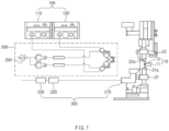
FIG. 1 is a schematic process view illustrating cleaning equipment of a sealing tool according to a first embodiment of the present invention. -
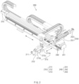
FIG. 2 is a front perspective view illustrating a torch device provided in the cleaning equipment of the sealing tool according to the first embodiment of the present invention. -
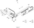
FIG. 3 is a rear perspective view illustrating the torch device provided in the cleaning equipment of the sealing tool according to the first embodiment of the present invention. -
FIG. 4 is a side view illustrating the torch device provided in the cleaning equipment of the sealing tool according to the first embodiment of the present invention. -
FIG. 5 is a partial enlarged view ofFIG. 2 . -
FIG. 6 is a partial enlarged view ofFIG. 5 . -
FIG. 7 is a side view ofFIG. 6 . -
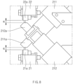
FIG. 8 is a partial enlarged view ofFIG. 6 . -
FIG. 9 is a partial enlarged view ofFIG. 3 . -
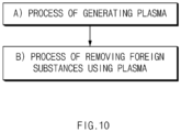
FIG. 10 is a flowchart illustrating a cleaning method of the sealing tool according to the first embodiment of the present invention. -
FIG. 11 is a perspective view illustrating a torch device of cleaning equipment of a sealing tool according to a second embodiment of the present invention. -
FIG. 12 is a side view ofFIG. 11 . - Hereinafter, embodiments of the present invention will be described in detail with reference to the accompanying drawings in such a manner that the technical idea of the present invention may easily be carried out by a person with ordinary skill in the art to which the invention pertains. The present invention may, however, be embodied in different forms and should not be construed as limited to the embodiments set forth herein. In the drawings, anything unnecessary for describing the present invention will be omitted for clarity, and also like reference numerals in the drawings denote like elements.
- Referring to
FIG. 1 , a secondary battery of the present invention includes an electrode assembly and a pouch 10 accommodating the electrode assembly. The pouch 10 includes an accommodation part 11 accommodating the electrode assembly and a sealingpart 12 sealing an edge of the accommodation part. - Here, the sealing
part 12 of the pouch 10 is sealed using a sealing tool 20, and the sealing tool 20 includes first andsecond sealing blocks second sealing blocks part 12. - The sealing tool 20 having such a structure has a problem in that foreign substances are accumulated on
pressing surfaces second sealing blocks - The foreign substances may be foreign matters, and the foreign substances may be polypropylene (PP) or polyethylene (PET) .
- If the foreign substances are accumulated on the
pressing surfaces second sealing blocks - In order to remove, particularly, automatically remove the foreign substances accumulated on the
pressing surfaces - That is, the cleaning equipment of the sealing tool according to the first embodiment of the present invention may remove the foreign substances accumulated on the
pressing surfaces - Hereinafter, the cleaning equipment of the sealing tool according to the first embodiment of the present invention will be described in detail with reference to the accompanying drawings.
- As illustrated in
FIGS. 1 to 9 , the cleaning equipment of the sealing tool according to the first embodiment of the present invention includes aplasma generation device 100, atorch device 200 automatically removing foreign substance accumulated onpressing surfaces plasma generation device 100, andexhaust device 300 removing smoke, odor, and harmful gases, which are generated when removing the foreign substances. - The
plasma generation device 100 is configured to generate the plasma. The plasma refers to a state in which a gas is heated at a ultra-high temperature and is separated into electrons and ions having positive charges. - Referring to
FIG. 1 , theplasma generation device 100 includes afirst plasma generator 110 and asecond plasma generator 120. Thefirst plasma generator 110 supplies the plasma to afirst torch member 211, and thesecond plasma generator 120 supplies the plasma to asecond torch member 212. - The plasma generation device is a commonly widely used device, and thus, detailed descriptions thereof will be omitted.
- Referring to
FIGS. 5 to 8 , thetorch device 200 is configured to remove the foreign substances accumulated on thepressing surfaces torch device 200 includes atorch head 210, a first movingmember 240, and a second movingmember 250. - The
torch head 210 has a structure which ejects the plasma generated by the plasma generation device to the pressing surfaces of the first and second sealing blocks to remove the foreign substances accumulated on the pressing surfaces of the first and second sealing blocks. That is, thetorch head 210 includes afirst torch member 211, asecond torch member 212 and atorch body 213. - The
first torch member 211 is provided with afirst plasma outlet 211a that ejects the plasma generated by the first plasma generator of the plasma generation device to thepressing surface 21a of thefirst sealing block 21. - The
second torch member 212 is provided with asecond plasma outlet 212a that ejects the plasma generated by the second plasma generator of the plasma generation device to thepressing surface 22a of thesecond sealing block 22. - The
torch body 213 has a structure which fixes thefirst torch member 211 in a state, in which thefirst plasma outlet 211a faces thepressing surface 21a of thefirst sealing block 21, and fixes thesecond torch member 212 in a state, in which thesecond plasma outlet 212a faces thepressing surface 22a of thesecond sealing block 22. - That is, the
torch body 213 includes a fixingplate 213a, afirst bracket 213b which is fixed to one end of the fixingplate 213a and to which thefirst torch member 211 is inclinedly coupled so that thefirst plasma outlet 211a faces the pressing surface of the first sealing block, and asecond bracket 213c which is fixed to the other end of the fixingplate 213a and to which thesecond torch member 212 is inclinedly coupled so that thesecond plasma outlet 212a faces the pressing surface of the second sealing block. - Referring to
FIG. 8 , thefirst plasma outlet 211a of thefirst torch member 211 has an effective distance α of 1.0 mm to 5.0 mm from thepressing surface 21a of thefirst sealing block 21, preferably has an effective distance (α) of 3.0 mm. That is, there is a distance of 1.0 mm to 5.0 mm between thefirst plasma outlet 211a and thepressing surface 21a of thefirst sealing block 21. In addition, thesecond plasma outlet 212a of thesecond torch member 212 has an effective distance of 1.0 mm to 5.0 mm from thepressing surface 22a of thesecond sealing block 22, preferably has an effective distance (α) of 3.0 mm. That is, there is a distance of 1.0 mm to 5.0 mm between thesecond plasma outlet 212a and thepressing surface 22a of thesecond sealing block 22. This is done for stably ejecting the plasma discharged from the plasma outlet to the pressing surface of the sealing block, and as a result, effectively removing the foreign substances accumulated on the pressing surface. - On the other hand, if the effective distance between the plasma outlet and the pressing surface is 1.0 mm or less, the plasma may not be effectively ejected over the entire pressing surface, and if the effective distance is 5.0 mm or more, there is a problem in that plasma efficiency is deteriorated.
- Referring to
FIG. 6 , the fixingplate 213a includes an upper plate which is provided at an upper right side with respect to a center line O and to which thefirst bracket 213b is fixed, and a lower plate which is provided at a lower left side with respect to the center line O and to which thesecond bracket 213c is fixed. In addition, the upper plate and the lower plate have a structure in which the plates are connected to each other. Thus, the fixingplate 213a may stably couple the first andsecond brackets 212b and 213c to each other. In particular, the first andsecond torch members - Referring to
FIG. 6 , thetorch head 210 further includes first and secondheight adjusting members second torch members second brackets 212b and 213c. That is, the first and secondheight adjusting members - For example, the first
height adjusting member 220 is configured to vertically adjust the height of the first torch member through the first bracket and includes afirst guide piece 221 to which thefirst bracket 213b is fixed and which is coupled to one end of the fixingplate 213a so as to be movable vertically, and afirst adjusting screw 222 which is screw-coupled to thefirst guide piece 221 by passing through oneplate 213f (a plate provided on an upper end of the fixing plate when viewed inFIG. 6 ) so that thefirst guide piece 221 moves upward or downward when the first adjusting screw rotates forward or backward. Thus, when the first adjustingscrew 222 rotates forward or backward, thefirst guide piece 221 may ascend or descend along a screw thread of the first adjustingscrew 222, and thefirst bracket 213b fixed to the guide piece may ascend or descend, and thus, thefirst torch member 211 coupled to thefirst bracket 213b may ascend or descend to adjust the height. This is done for adjusting the effective distance between the first plasma outlet and the pressing surface of the first sealing block. - In addition, the second
height adjusting member 230 includes asecond guide piece 231 to which thesecond bracket 213c is fixed and which is coupled to the other end of the fixingplate 213a so as to be movable vertically, and asecond adjusting screw 232 which is screw-coupled to thesecond guide piece 231 by passing through theother plate 213g (a plate provided on a lower end of the fixing plate when viewed inFIG. 6 ) so that thesecond guide piece 231 moves upward or downward when the second adjusting screw rotates forward or backward. Thus, when thesecond adjusting screw 232 rotates forward or backward, thesecond guide piece 231 may ascend or descend along a screw thread of thesecond adjusting screw 232, and thesecond bracket 213c fixed to the guide piece may ascend or descend, and thus, thesecond torch member 212 coupled to thesecond bracket 213c may ascend or descend to adjust the height. This is done for adjusting the effective distance between the second plasma outlet and the pressing surface of the second sealing block. - Referring to
FIG. 2 , thetorch device 200 may include a first movingmember 240 through which thetorch head 210 moves in a longitudinal direction (left and right direction when viewed inFIG. 2 ) of the first and second sealing blocks to remove the foreign substances accumulated on the entire pressing surfaces of the first and second sealing blocks. - The first moving
member 240 includes aguide rail 241 disposed in the longitudinal direction (left and right direction when viewed inFIG. 2 ) of the first and second sealing blocks, aguide piece 242 which is provided on theguide rail 241 so as to be movable in the longitudinal direction of the first and second sealing blocks and on which thetorch head 210 is provided, and afirst driving piece 243 through which theguide piece 242 moves in the longitudinal direction of the first and second sealing blocks or returns to its original position. - That is, when the
first driving piece 243 operates, the first movingmember 240 may allow the guide piece to move in the longitudinal direction of the first and second sealing blocks along theguide rail 241. Here, thetorch head 210 fixed to theguide piece 242 may move to be interlocked, thereby removing the foreign substances accumulated on the entire pressing surfaces of the first and second sealing blocks. Here, the first movingmember 240 may be a driving motor. - Referring to
FIG. 3 , thetorch device 200 may include a second movingmember 250 through which the torch device moves forward so that thetorch head 210 is disposed on the pressing surfaces of the first and second sealing blocks 21 and 22 only when removing the foreign substances accumulated on the pressing surfaces of the first and second sealing blocks 21 and 22. - That is, the second moving
member 250 includes amovable piece 251 provided between theguide piece 242 and thetorch head 210 and asecond driving piece 252 through which thetorch head 210 provided on themovable piece 251 moves forward toward the pressing surfaces of the first and second sealing blocks or move backward. Thus, when thesecond driving piece 252 operates, thetorch head 210 may move forward toward the pressing surfaces of the first and second sealing blocks or move backward. Here, thesecond driving piece 252 may be an electric cylinder. - The second moving
member 250 may further include aguide rod 253 that guides thetorch head 210 so that thetorch head 210 moves straightly toward the pressing surfaces of the first and second sealing blocks. Theguide rod 253 has one end fixed to the fixingplate 213a of thetorch head 210 and the other end coupled to a vertical piece provided on themovable piece 251 so as to be movable toward the pressing surfaces of the first and second sealing blocks. - The
torch device 200 may further include anair supply member 260 that ejects air together with the plasma to the pressing surfaces of the first and second sealing blocks. - Therefore, the
torch device 200 may stably eject the plasma supplied from the plasma generation device to the pressing surfaces of the first and second sealing blocks, and as a result, effectively remove the foreign substances accumulated on the pressing surfaces of the first and second sealing blocks. - Referring to
FIG. 1 , theexhaust device 300 is configured to remove smoke, odor, and harmful gases, which are generated while the foreign substances accumulated on the pressing surfaces of the first and second sealing blocks are removed. That is, theexhaust device 300 includes anexhaust tube 310 which is disposed close to thepressing surfaces filter 320 configured to filter the smoke, the odor, and the harmful gases, which are inhaled into theexhaust tube 310. - Here, the
exhaust device 300 may generate ozone (O3) by a chemical reaction between the plasma and the foreign substances and may further include anozone remover 330 to remove the ozone. - Thus, the
exhaust device 300 may effectively remove the harmful gases generated while the foreign substances accumulated on thepressing surfaces - Therefore, the cleaning equipment of the sealing tool according to the first embodiment of the present invention may effectively remove the foreign substances accumulated on the pressing surfaces of the first and second sealing blocks by using the plasma, thereby maintaining the sealing quality, in particular, improving the work efficiency.
- Hereinafter, a cleaning method of the sealing tool according to the first embodiment of the present invention will be described.
- As illustrated in
FIG. 10 , the cleaning method of the sealing tool according to the first embodiment of the present invention is performed to remove foreign substances accumulated onpressing surfaces - That is, the cleaning method of the sealing tool according to the first embodiment of the present invention includes a process (a) of generating plasma through a
plasma generation device 100; and a process (b) of ejecting the plasma generated by theplasma generation device 100 to thepressing surfaces pressing surfaces - A
torch device 200 includes atorch head 210, a firstheight adjusting member 220, a secondheight adjusting member 230, a first movingmember 240, a second movingmember 250, and anair supply member 260. In addition, thetorch head 210 includes afirst torch member 211 and asecond torch member 212. - Here, in the process (b), the plasma generated in the
plasma generation device 100 may be ejected to thepressing surface 21a of thefirst sealing block 21 through afirst plasma outlet 211a of thefirst torch member 211 coupled to one end of atorch body 213, and the plasma generated in theplasma generation device 100 may be ejected to thepressing surface 22a of thesecond sealing block 22 through a second plasma outlet of thesecond torch member 212 coupled to the other end of atorch body 213. Thus, the foreign substances accumulated on the pressing surfaces of the first and second sealing blocks may be removed. - For example, in the process (b), most of the foreign substances accumulated on the pressing surface may be organic materials (polypropylene, polyethylene), and when the plasma is ejected on the pressing surface, radical oxygen (O) existing in the plasma and carbon (C), hydrogen (H), and oxygen (O), which exist in the foreign substances, chemically react with each other to form carbon dioxide (CO2) and water (H2O) so as to be removed.
[Chemical formula] C+2O=CO2 2H+O=H2O
- Before performing the process (a), a process of allowing the
torch device 200 to move forward toward thepressing surfaces first plasma outlet 211a of thefirst torch member 211 is disposed to be spaced an effective distance from the pressing surface of the first sealing block, and the second plasma outlet 121a of thesecond torch member 212 is disposed to be spaced an effective distance from the pressing surface of the second sealing block may be further performed. - That is, when there is no need to remove the foreign substances, the torch device is disposed to be spaced a set distance from the sealing tool. Thereafter, when removal of the foreign substances is required, the
torch device 200 may move forward toward the sealing tool through the second movingmember 250, and thus, thetorch head 210 may be disposed on the pressing surfaces of the first and second sealing blocks 21 and 22. - The process (b) may further includes a process of allowing the
torch device 200 to move in a longitudinal direction of the first and second sealing blocks, thereby removing the foreign substances accumulated on the entire pressing surfaces of the first and second sealing blocks. - That is, in the process (b), the
torch device 200 may move in the longitudinal direction of the first and second sealing blocks through the first movingmember 240 or return to its original position, and thus, the first and second torch members may pass through the entire pressing surfaces of the first and second sealing blocks, and as a result, the foreign substances accumulated on the entire pressing surfaces may be removed. - The process (b) may further include a process of removing the smoke, the odor, and the harmful gases, which are generated during the removal of the foreign substances by inhaling the smoke, the odor, and the harmful gases through the
exhaust device 300. - That is, the
exhaust device 300 may inhale the smoke, the odor, and the harmful gases, which are generated while the foreign substances accumulated on the pressing surfaces of the first and second sealing blocks are removed through theexhaust tube 310 in which the inhaler is installed, and the smoke, the odor, and the harmful gases may be filtered through afilter 320 so as to be removed. Particularly, theexhaust device 300 includes an ozone remover, and thus ozone generated by a chemical reaction between the plasma and the foreign substances may be removed. - Therefore, in the cleaning method of the sealing tool according to the first embodiment of the present invention, the foreign substances accumulated on the pressing surfaces of the first and second sealing blocks may be removed through the above processes.
- Hereinafter, in descriptions of another embodiment of the present invention, constituents having the same function as the above-mentioned embodiment have been given the same reference numeral in the drawings, and thus duplicated description will be omitted.
- As illustrated in
FIGS. 11 and12 , cleaning equipment of a sealing tool according to a second embodiment of the present invention may include aplasma generator 100 and atorch device 200 having atorch head 210, and thetorch head 210 may include afirst torch member 211, asecond torch member 212 and atorch body 213. - Here, the
torch body 213 may include a firstangle adjusting piece 213b through which thefirst torch member 211 is coupled to afirst bracket 213b so as to be adjustable in angle toward a pressing surface of a first sealing block. - That is, the first
angle adjusting piece 213d has a bolt structure that is capable of being tightened or loosened and may be screw-coupled to a side portion of the first sealing block by passing through thefirst bracket 213b. Thus, when the firstangle adjusting piece 213d is loosened, an angle of the first sealing block may be adjusted in a vertical direction when viewed inFIG. 12 , with respect to the firstangle adjusting piece 213d, and when the firstangle adjusting piece 213d is tightened, the first sealing block may be compressed to thefirst bracket 213b, thereby fixing the first sealing block. - In addition, the
torch body 213 may include a secondangle adjusting piece 213e through which thesecond torch member 212 is coupled to asecond bracket 213c so as to be adjustable in angle toward a pressing surface of a second sealing block. - That is, the second
angle adjusting piece 213e has a bolt structure that is capable of being tightened or loosened and may be screw-coupled to a side portion of the second sealing block by passing through thesecond bracket 213b. Thus, when the secondangle adjusting piece 213e is loosened, an angle of the second sealing block may be adjusted in the vertical direction when viewed inFIG. 12 , with respect to the secondangle adjusting piece 213e, and when the secondangle adjusting piece 213e is tightened, the second sealing block may be compressed to thesecond bracket 213c, thereby fixing the second sealing block. - Therefore, the cleaning equipment of the sealing tool according to the second embodiment of the present invention may include the first and second
angle adjusting pieces - Accordingly, the scope of the present invention is defined by the appended claims more than the foregoing description and the exemplary embodiments described therein. Various modifications made within the meaning of an equivalent of the claims of the invention and within the claims are to be regarded to be in the scope of the present invention.
-
- 10: Pouch
- 11: Accommodation part
- 12: Sealing part
- 20: Sealing tool
- 21: First sealing block
- 21a: Pressing surface
- 22: Second sealing block
- 22a: Pressing surface
- 100: Plasma generation device
- 200: Torch device
- 210: Torch head
- 211: First torch member
- 212: Second torch member
- 213: Torch body
- 213a: Fixing plate
- 213b: First bracket
- 213c: Second bracket
- 213d: First angle adjusting piece
- 213e: Second angle adjusting piece
- 220: First height adjusting member
- 221: First guide piece
- 222: First adjusting screw
- 230: Second height adjusting member
- 231: Second guide piece
- 232: Second adjusting screw
- 240: First moving member
- 241: Guide rail
- 242: Guide piece
- 243: First driving piece
- 250: Second moving member
- 251: Movable piece
- 252: Second driving piece
- 260: Air supply member
- 300: Exhaust device
- 310: Exhaust tube
- 320: Filter
- 330: Ozone remover
Claims (15)
- Cleaning equipment of a sealing tool, which is configured to remove foreign substances accumulated on first and second sealing blocks provided symmetrically in a vertical direction, the cleaning equipment comprising:a plasma generation device configured to generate plasma; anda torch device provided with a torch head configured to eject the plasma generated in the plasma generation device to pressing surfaces of the first and second sealing blocks so as to remove the foreign substances accumulated on the pressing surfaces of the first and second sealing blocks,wherein the torch head comprises:a first torch member provided with a first plasma outlet configured to eject the plasma generated in the plasma generation device to the pressing surface of the first sealing block; anda second torch member provided with a second plasma outlet configured to eject the plasma generated in the plasma generation device to the pressing surface of the second sealing block.
- The cleaning equipment of claim 1, wherein the torch head further comprises a torch body to which the first torch member and the second torch member are coupled,
wherein the torch body comprises:a fixing plate;a first bracket which is provided on one end of the fixing plate and to which the first torch member is inclinedly coupled so that the first plasma outlet faces the pressing surface of the first sealing block; anda second bracket which is provided to the other end of the fixing plate and to which the second torch member is inclinedly coupled so that the second plasma outlet faces the pressing surface of the second sealing block. - The cleaning equipment of claim 2, wherein the first plasma outlet of the first torch member is spaced to be spaced a distance of 1.0 mm to 5.0 mm from the pressing surface of the first sealing block, and
the second plasma outlet of the second torch member is spaced to be spaced a distance of 1.0 mm to 5.0 mm from the pressing surface of the second sealing block. - The cleaning equipment of claim 2, wherein the torch body further comprises:a first angle adjusting piece through which the first torch member is coupled to the first bracket so as to be adjustable in angle toward the pressing surface of the first sealing block; anda second angle adjusting piece through which the second torch member is coupled to the second bracket so as to be adjustable in angle toward the pressing surface of the second sealing block.
- The cleaning equipment of claim 2, wherein the torch head further comprises:a first height adjusting member through which the first bracket is coupled to one end of the fixing plate so as to be movable vertically; anda second height adjusting member through which the second bracket is coupled to the other end of the fixing plate so as to be movable vertically.
- The cleaning equipment of claim 5, wherein the first height adjusting member comprises:a first guide piece to which the first bracket is fixed and which is coupled to one end of the fixing plate so as to be movable vertically; anda first adjusting screw which is screw-coupled to the first guide piece by passing through one plate of the fixing plate, wherein, when the first adjusting screw rotates forward or backward, the first guide piece moves upward or downward, andthe second height adjusting member comprises:a second guide piece to which the second bracket is fixed and which is coupled to the other end of the fixing plate so as to be movable vertically; anda second adjusting screw which is screw-coupled to the second guide piece by passing through the other plate of the fixing plate, wherein, when the second adjusting screw rotates forward or backward, the second guide piece moves upward or downward.
- The cleaning equipment of claim 1, wherein the torch device further comprises a first moving member configured to allow the torch head to move in a longitudinal direction of the first and second sealing blocks,
wherein the first moving member comprises:a guide rail disposed in a longitudinal direction of the first and second sealing blocks;a guide piece configured to allow the torch head to be movable in the longitudinal direction of the first and second sealing blocks; anda first driving piece configured to allow the guide piece to move in the longitudinal direction of the first and second sealing blocks. - The cleaning equipment of claim 7, wherein the torch device comprises a second moving member configured to allow the torch head to move forward in a width direction of the first and second sealing blocks so that the torch head is disposed on the pressing surfaces of the first and second sealing blocks or returns to its original position,
wherein the second moving member comprises:a movable piece provided between the guide piece and the torch head; anda second driving piece configured to allow the torch head to move forward in the width direction of the first and second sealing blocks provided on the movable piece so that the torch head is disposed on the pressing surfaces of the first and second sealing blocks or returns to its original position. - The cleaning equipment of claim 1, further comprising an exhaust device configured to remove smoke, odor, and harmful gases, which are generated while the foreign substances accumulated on the pressing surfaces of the first and second sealing blocks are removed.
- The cleaning equipment of claim 9, wherein the exhaust device comprises an ozone remover configured to remove ozone contained in the harmful gases.
- A cleaning method of a sealing tool, which is performed to remove foreign substances accumulated on first and second sealing blocks provided symmetrically in a vertical direction, the cleaning method comprising:a process (a) of generating plasma through a plasma generation device; anda process (b) of ejecting the plasma generated by the plasma generation device to pressing surfaces of the first and second sealing blocks to remove the foreign substances accumulated on the pressing surfaces of the first and second sealing blocks,wherein, in the process (b), the plasma generated in the plasma generation device is ejected to the pressing surface of the first sealing block through a first torch member provided in the torch head, and the plasma generated in the plasma generation device is ejected to the pressing surface of the second sealing block through a second torch member provided in the torch head to remove the foreign substances accumulated on the pressing surfaces of the first and second sealing blocks.
- The cleaning method of claim 11, wherein, in the process (b), when the plasma is ejected on the pressing surface, radical oxygen (O) existing in the plasma and carbon (C), hydrogen (H), and oxygen (O), which exist in the foreign substances, chemically react with each other to form carbon dioxide (CO2) and water (H2O) so as to be removed.
- The cleaning method of claim 11, further comprising, before performing the process (a), a process of allowing the torch device to move forward toward the first and second sealing blocks so that first and second torch members of the torch head are disposed to be spaced an effective distance from the pressing surfaces of the first and second sealing blocks.
- The cleaning method of claim 11, wherein the process (b) further comprises a process of allowing the torch device to move in a longitudinal direction of the first and second sealing blocks, thereby removing the foreign substances accumulated on the entire pressing surfaces of the first and second sealing blocks.
- The cleaning method of claim 11, wherein the process (b) further comprises a process of inhaling and removing smoke, odor, and harmful gases, which are generated while the foreign substances are removed, through an exhaust device.
Applications Claiming Priority (2)
| Application Number | Priority Date | Filing Date | Title |
|---|---|---|---|
| KR1020210140230A KR102938553B1 (en) | 2021-10-20 | 2021-10-20 | Cleaning equipment and cleaning method of sealing tool |
| PCT/KR2022/015523 WO2023068658A1 (en) | 2021-10-20 | 2022-10-13 | Sealing tool cleaning apparatus and cleaning method |
Publications (3)
| Publication Number | Publication Date |
|---|---|
| EP4282547A1 true EP4282547A1 (en) | 2023-11-29 |
| EP4282547A4 EP4282547A4 (en) | 2024-09-04 |
| EP4282547B1 EP4282547B1 (en) | 2025-05-14 |
Family
ID=86058255
Family Applications (1)
| Application Number | Title | Priority Date | Filing Date |
|---|---|---|---|
| EP22883881.9A Active EP4282547B1 (en) | 2021-10-20 | 2022-10-13 | Cleaning equipment and cleaning method of sealing tool |
Country Status (8)
| Country | Link |
|---|---|
| US (1) | US12564870B2 (en) |
| EP (1) | EP4282547B1 (en) |
| JP (1) | JP7582583B2 (en) |
| KR (2) | KR102938553B1 (en) |
| CN (1) | CN116963846B (en) |
| ES (1) | ES3037984T3 (en) |
| HU (1) | HUE071865T2 (en) |
| WO (1) | WO2023068658A1 (en) |
Families Citing this family (2)
| Publication number | Priority date | Publication date | Assignee | Title |
|---|---|---|---|---|
| CN118455196A (en) * | 2024-06-03 | 2024-08-09 | 苏州源永动电子有限公司 | Spray head for clamping piece type wide-width plasma cleaning machine |
| CN118455199A (en) * | 2024-06-19 | 2024-08-09 | 珠海格力电器股份有限公司 | Plasma module cleaning device and plasma module cleaning control method |
Family Cites Families (27)
| Publication number | Priority date | Publication date | Assignee | Title |
|---|---|---|---|---|
| JP3784663B2 (en) * | 2001-05-15 | 2006-06-14 | 株式会社フジキカイ | Seal body cleaning device |
| KR100967702B1 (en) | 2003-06-02 | 2010-07-07 | 주식회사 포스코 | Apparatus supporting gap between parent metal and plasma touch |
| JP4700570B2 (en) | 2006-07-14 | 2011-06-15 | 株式会社新川 | Bonding apparatus, bonding tool tip cleaning method and program |
| KR101050047B1 (en) | 2009-09-29 | 2011-07-19 | 최의수 | Automatic welding carriage for easy torch length and angle adjustment |
| KR101107077B1 (en) * | 2010-06-10 | 2012-01-20 | 삼성에스디아이 주식회사 | Plasma cleaning device |
| KR101453784B1 (en) | 2011-12-21 | 2014-10-23 | 주식회사 엘지화학 | Apparatus and method for sealing pouch for secondary battery |
| DE102012107282A1 (en) * | 2012-01-17 | 2013-07-18 | Reinhausen Plasma Gmbh | DEVICE AND METHOD FOR PLASMA TREATMENT OF SURFACES |
| KR20160090658A (en) | 2015-01-22 | 2016-08-01 | 주식회사 글로벌스탠다드테크놀로지 | Non-degradable noxious gas treatment system using the same process |
| KR102174607B1 (en) * | 2016-09-09 | 2020-11-05 | 주식회사 엘지화학 | Sealing Device for Battery Case Comprising Sealing Protrusion and Method of Manufacturing Battery Cell Using the Same |
| CN106783711A (en) * | 2016-12-31 | 2017-05-31 | 合肥优亿科机电科技有限公司 | Plasma clean photovoltaic silicon wafer organic dirt equipment |
| CN207013387U (en) * | 2017-04-28 | 2018-02-16 | 苏州巨一智能装备有限公司 | A kind of Hard Roll battery core surface automatic cleaning equipment |
| CN208033200U (en) * | 2017-12-29 | 2018-11-02 | 瑞立集团瑞安汽车零部件有限公司 | A kind of self-cleaning valve door machine |
| CN108325923B (en) * | 2018-01-10 | 2020-11-17 | 浙江衡远新能源科技有限公司 | Cleaning device for sealing head of packaging machine |
| KR101983372B1 (en) * | 2018-01-14 | 2019-05-28 | (주)현성인터텍 | Pure laminating equipment for cleansing and dust elimination |
| CN208429304U (en) * | 2018-04-25 | 2019-01-25 | 安徽诚合包装有限公司 | A kind of upper sealing pressing block cleaning assembly of plastic compound bag closing device |
| CN208712410U (en) * | 2018-04-28 | 2019-04-09 | 哈沃科技(天津)有限公司 | Sealing head cleaning structure |
| KR102186957B1 (en) | 2019-01-03 | 2020-12-04 | (주) 엠에이케이 | A method for cleaning the electrode tap of the secondary battery |
| CN110180838A (en) * | 2019-06-20 | 2019-08-30 | 深圳市研创精密设备有限公司 | A kind of automobile power cell plasma cleaner |
| KR102105331B1 (en) | 2019-07-26 | 2020-04-28 | 주식회사 진영코퍼레이션 | Cleaning nozzle for supplying X-ray and plasma and PCB cleaning apparatus including the cleaning nozzle |
| CN210304891U (en) * | 2019-07-30 | 2020-04-14 | 深圳市誉娇诚科技有限公司 | Cleaning device capable of improving welding firmness of lithium power battery pack |
| KR20210041983A (en) | 2019-10-08 | 2021-04-16 | 주식회사 에이아이코리아 | Dry Cleaning Device Using Atomospheric Plasma |
| CN110758844A (en) * | 2019-10-22 | 2020-02-07 | 浙江诗韵医疗科技有限公司 | Cleaning device for efficient mask sealing device |
| CN110695004A (en) * | 2019-11-05 | 2020-01-17 | 上海先惠自动化技术股份有限公司 | Cleaning device for soft-packaged battery cell fixing box |
| CN110801971A (en) * | 2019-11-28 | 2020-02-18 | 广东震仪智能装备股份有限公司 | Glass coating spraying equipment |
| KR20210068922A (en) * | 2019-12-02 | 2021-06-10 | (주)폴리바이오텍 | Low temperature atmospheric plasma generator for promoting prosthetic bonding |
| JP6871556B2 (en) | 2019-12-02 | 2021-05-12 | アルファ株式会社 | Plasma processing equipment and plasma torch |
| CN212760132U (en) * | 2020-07-29 | 2021-03-23 | 中航锂电技术研究院有限公司 | Guards and Plasma Cleaners |
-
2021
- 2021-10-20 KR KR1020210140230A patent/KR102938553B1/en active Active
-
2022
- 2022-10-13 EP EP22883881.9A patent/EP4282547B1/en active Active
- 2022-10-13 JP JP2023550278A patent/JP7582583B2/en active Active
- 2022-10-13 HU HUE22883881A patent/HUE071865T2/en unknown
- 2022-10-13 US US18/281,493 patent/US12564870B2/en active Active
- 2022-10-13 ES ES22883881T patent/ES3037984T3/en active Active
- 2022-10-13 CN CN202280020637.XA patent/CN116963846B/en active Active
- 2022-10-13 WO PCT/KR2022/015523 patent/WO2023068658A1/en not_active Ceased
-
2026
- 2026-03-06 KR KR1020260040389A patent/KR20260042113A/en active Pending
Also Published As
| Publication number | Publication date |
|---|---|
| EP4282547A4 (en) | 2024-09-04 |
| JP7582583B2 (en) | 2024-11-13 |
| US20240149313A1 (en) | 2024-05-09 |
| EP4282547B1 (en) | 2025-05-14 |
| WO2023068658A1 (en) | 2023-04-27 |
| ES3037984T3 (en) | 2025-10-08 |
| US12564870B2 (en) | 2026-03-03 |
| KR20230056328A (en) | 2023-04-27 |
| KR20260042113A (en) | 2026-03-30 |
| JP2024508436A (en) | 2024-02-27 |
| HUE071865T2 (en) | 2025-09-28 |
| KR102938553B1 (en) | 2026-03-13 |
| CN116963846B (en) | 2025-12-23 |
| CN116963846A (en) | 2023-10-27 |
Similar Documents
| Publication | Publication Date | Title |
|---|---|---|
| EP4282547B1 (en) | Cleaning equipment and cleaning method of sealing tool | |
| CN101460663B (en) | System and process for collecting effluents from an electrolytic cell | |
| EP1715937B1 (en) | Methods and apparatuses for treating a fluorocompound-containing gas stream | |
| EP1775012A3 (en) | Method and apparatus for treating perflourocompound gas | |
| CN1442928A (en) | Method and apparatus for decomposing and storing articles containing alkali metals, such as alkali metal-containing batteries | |
| US20090236320A1 (en) | Method for tandem gas metal arc welding, and welding torch and welding apparatus used therefor | |
| US11058984B2 (en) | Method for treating sulfur hexafluoride using radiation and apparatus for collecting and treating by-products | |
| KR20200022215A (en) | device for collecting and recycling chemical powder of fire extinguisher | |
| US20230198041A1 (en) | Opening an end-of-life battery | |
| EP1865255A2 (en) | Apparatus for treating a waste gas using plasma torch | |
| JP2004001043A (en) | Method and apparatus for removing fumes during laser processing | |
| CN219084509U (en) | Gas sampling device in battery | |
| CN223420112U (en) | Sealing tool cleaning device | |
| CN217848021U (en) | Flat formula of lying punctures, evacuation and encapsulation all-in-one and battery processing equipment convenient to maintain | |
| CN207681113U (en) | A kind of screw dust cleaning device | |
| CN212418253U (en) | Electrified breaker of waste battery and waste battery recovery system | |
| CN102699502A (en) | Wet type liftable dust removal workbench for plasma cutting machine | |
| US20250128355A1 (en) | Secondary battery electrode production system | |
| CN113089031A (en) | Electrolytic aluminum waste gas processing apparatus | |
| CN218887244U (en) | Fuel cell with purging structure | |
| CN217596148U (en) | Plasma protection device used on electric arc welding gun | |
| JP2026513065A (en) | Electrolyte removal device | |
| CN110681964A (en) | Argon supply recovery device and welding method | |
| RU2001101618A (en) | METHOD OF EMERGENCY EXPLOSION OF UNDERWATER VEHICLES AND DEVICE FOR ITS IMPLEMENTATION | |
| CN201728215U (en) | Unloading and dedusting device in sponge iron production line |
Legal Events
| Date | Code | Title | Description |
|---|---|---|---|
| STAA | Information on the status of an ep patent application or granted ep patent |
Free format text: STATUS: THE INTERNATIONAL PUBLICATION HAS BEEN MADE |
|
| PUAI | Public reference made under article 153(3) epc to a published international application that has entered the european phase |
Free format text: ORIGINAL CODE: 0009012 |
|
| STAA | Information on the status of an ep patent application or granted ep patent |
Free format text: STATUS: REQUEST FOR EXAMINATION WAS MADE |
|
| 17P | Request for examination filed |
Effective date: 20230824 |
|
| AK | Designated contracting states |
Kind code of ref document: A1 Designated state(s): AL AT BE BG CH CY CZ DE DK EE ES FI FR GB GR HR HU IE IS IT LI LT LU LV MC ME MK MT NL NO PL PT RO RS SE SI SK SM TR |
|
| A4 | Supplementary search report drawn up and despatched |
Effective date: 20240805 |
|
| RIC1 | Information provided on ipc code assigned before grant |
Ipc: H01M 10/04 20060101ALI20240730BHEP Ipc: B05B 7/22 20060101ALI20240730BHEP Ipc: B08B 5/04 20060101ALI20240730BHEP Ipc: B08B 7/00 20060101AFI20240730BHEP |
|
| DAV | Request for validation of the european patent (deleted) | ||
| DAX | Request for extension of the european patent (deleted) | ||
| RIC1 | Information provided on ipc code assigned before grant |
Ipc: H01M 10/04 20060101ALI20250110BHEP Ipc: B05B 7/22 20060101ALI20250110BHEP Ipc: B08B 5/04 20060101ALI20250110BHEP Ipc: B08B 7/00 20060101AFI20250110BHEP |
|
| GRAP | Despatch of communication of intention to grant a patent |
Free format text: ORIGINAL CODE: EPIDOSNIGR1 |
|
| STAA | Information on the status of an ep patent application or granted ep patent |
Free format text: STATUS: GRANT OF PATENT IS INTENDED |
|
| INTG | Intention to grant announced |
Effective date: 20250224 |
|
| GRAS | Grant fee paid |
Free format text: ORIGINAL CODE: EPIDOSNIGR3 |
|
| GRAA | (expected) grant |
Free format text: ORIGINAL CODE: 0009210 |
|
| STAA | Information on the status of an ep patent application or granted ep patent |
Free format text: STATUS: THE PATENT HAS BEEN GRANTED |
|
| P01 | Opt-out of the competence of the unified patent court (upc) registered |
Free format text: CASE NUMBER: APP_11872/2025 Effective date: 20250311 |
|
| AK | Designated contracting states |
Kind code of ref document: B1 Designated state(s): AL AT BE BG CH CY CZ DE DK EE ES FI FR GB GR HR HU IE IS IT LI LT LU LV MC ME MK MT NL NO PL PT RO RS SE SI SK SM TR |
|
| REG | Reference to a national code |
Ref country code: GB Ref legal event code: FG4D |
|
| REG | Reference to a national code |
Ref country code: CH Ref legal event code: EP |
|
| REG | Reference to a national code |
Ref country code: DE Ref legal event code: R096 Ref document number: 602022014791 Country of ref document: DE |
|
| REG | Reference to a national code |
Ref country code: IE Ref legal event code: FG4D |
|
| REG | Reference to a national code |
Ref country code: NL Ref legal event code: MP Effective date: 20250514 |
|
| REG | Reference to a national code |
Ref country code: HU Ref legal event code: AG4A Ref document number: E071865 Country of ref document: HU |
|
| REG | Reference to a national code |
Ref country code: ES Ref legal event code: FG2A Ref document number: 3037984 Country of ref document: ES Kind code of ref document: T3 Effective date: 20251008 |
|
| PG25 | Lapsed in a contracting state [announced via postgrant information from national office to epo] |
Ref country code: FI Free format text: LAPSE BECAUSE OF FAILURE TO SUBMIT A TRANSLATION OF THE DESCRIPTION OR TO PAY THE FEE WITHIN THE PRESCRIBED TIME-LIMIT Effective date: 20250514 Ref country code: PT Free format text: LAPSE BECAUSE OF FAILURE TO SUBMIT A TRANSLATION OF THE DESCRIPTION OR TO PAY THE FEE WITHIN THE PRESCRIBED TIME-LIMIT Effective date: 20250915 |
|
| REG | Reference to a national code |
Ref country code: LT Ref legal event code: MG9D |
|
| PG25 | Lapsed in a contracting state [announced via postgrant information from national office to epo] |
Ref country code: GR Free format text: LAPSE BECAUSE OF FAILURE TO SUBMIT A TRANSLATION OF THE DESCRIPTION OR TO PAY THE FEE WITHIN THE PRESCRIBED TIME-LIMIT Effective date: 20250815 Ref country code: NO Free format text: LAPSE BECAUSE OF FAILURE TO SUBMIT A TRANSLATION OF THE DESCRIPTION OR TO PAY THE FEE WITHIN THE PRESCRIBED TIME-LIMIT Effective date: 20250814 |
|
| PG25 | Lapsed in a contracting state [announced via postgrant information from national office to epo] |
Ref country code: NL Free format text: LAPSE BECAUSE OF FAILURE TO SUBMIT A TRANSLATION OF THE DESCRIPTION OR TO PAY THE FEE WITHIN THE PRESCRIBED TIME-LIMIT Effective date: 20250514 Ref country code: PL Free format text: LAPSE BECAUSE OF FAILURE TO SUBMIT A TRANSLATION OF THE DESCRIPTION OR TO PAY THE FEE WITHIN THE PRESCRIBED TIME-LIMIT Effective date: 20250514 |
|
| REG | Reference to a national code |
Ref country code: AT Ref legal event code: MK05 Ref document number: 1794392 Country of ref document: AT Kind code of ref document: T Effective date: 20250514 |
|
| PG25 | Lapsed in a contracting state [announced via postgrant information from national office to epo] |
Ref country code: BG Free format text: LAPSE BECAUSE OF FAILURE TO SUBMIT A TRANSLATION OF THE DESCRIPTION OR TO PAY THE FEE WITHIN THE PRESCRIBED TIME-LIMIT Effective date: 20250514 |
|
| PGFP | Annual fee paid to national office [announced via postgrant information from national office to epo] |
Ref country code: BE Payment date: 20250922 Year of fee payment: 4 |
|
| PG25 | Lapsed in a contracting state [announced via postgrant information from national office to epo] |
Ref country code: HR Free format text: LAPSE BECAUSE OF FAILURE TO SUBMIT A TRANSLATION OF THE DESCRIPTION OR TO PAY THE FEE WITHIN THE PRESCRIBED TIME-LIMIT Effective date: 20250514 |
|
| PG25 | Lapsed in a contracting state [announced via postgrant information from national office to epo] |
Ref country code: AT Free format text: LAPSE BECAUSE OF FAILURE TO SUBMIT A TRANSLATION OF THE DESCRIPTION OR TO PAY THE FEE WITHIN THE PRESCRIBED TIME-LIMIT Effective date: 20250514 |
|
| PGFP | Annual fee paid to national office [announced via postgrant information from national office to epo] |
Ref country code: FR Payment date: 20250925 Year of fee payment: 4 |
|
| PG25 | Lapsed in a contracting state [announced via postgrant information from national office to epo] |
Ref country code: RS Free format text: LAPSE BECAUSE OF FAILURE TO SUBMIT A TRANSLATION OF THE DESCRIPTION OR TO PAY THE FEE WITHIN THE PRESCRIBED TIME-LIMIT Effective date: 20250814 |
|
| PG25 | Lapsed in a contracting state [announced via postgrant information from national office to epo] |
Ref country code: IS Free format text: LAPSE BECAUSE OF FAILURE TO SUBMIT A TRANSLATION OF THE DESCRIPTION OR TO PAY THE FEE WITHIN THE PRESCRIBED TIME-LIMIT Effective date: 20250914 |
|
| PG25 | Lapsed in a contracting state [announced via postgrant information from national office to epo] |
Ref country code: LV Free format text: LAPSE BECAUSE OF FAILURE TO SUBMIT A TRANSLATION OF THE DESCRIPTION OR TO PAY THE FEE WITHIN THE PRESCRIBED TIME-LIMIT Effective date: 20250514 |
|
| PGFP | Annual fee paid to national office [announced via postgrant information from national office to epo] |
Ref country code: HU Payment date: 20251029 Year of fee payment: 4 |
|
| PGFP | Annual fee paid to national office [announced via postgrant information from national office to epo] |
Ref country code: DE Payment date: 20250922 Year of fee payment: 4 |
|
| PG25 | Lapsed in a contracting state [announced via postgrant information from national office to epo] |
Ref country code: SM Free format text: LAPSE BECAUSE OF FAILURE TO SUBMIT A TRANSLATION OF THE DESCRIPTION OR TO PAY THE FEE WITHIN THE PRESCRIBED TIME-LIMIT Effective date: 20250514 Ref country code: DK Free format text: LAPSE BECAUSE OF FAILURE TO SUBMIT A TRANSLATION OF THE DESCRIPTION OR TO PAY THE FEE WITHIN THE PRESCRIBED TIME-LIMIT Effective date: 20250514 |
|
| PG25 | Lapsed in a contracting state [announced via postgrant information from national office to epo] |
Ref country code: CZ Free format text: LAPSE BECAUSE OF FAILURE TO SUBMIT A TRANSLATION OF THE DESCRIPTION OR TO PAY THE FEE WITHIN THE PRESCRIBED TIME-LIMIT Effective date: 20250514 |
|
| PG25 | Lapsed in a contracting state [announced via postgrant information from national office to epo] |
Ref country code: EE Free format text: LAPSE BECAUSE OF FAILURE TO SUBMIT A TRANSLATION OF THE DESCRIPTION OR TO PAY THE FEE WITHIN THE PRESCRIBED TIME-LIMIT Effective date: 20250514 |
|
| PG25 | Lapsed in a contracting state [announced via postgrant information from national office to epo] |
Ref country code: SK Free format text: LAPSE BECAUSE OF FAILURE TO SUBMIT A TRANSLATION OF THE DESCRIPTION OR TO PAY THE FEE WITHIN THE PRESCRIBED TIME-LIMIT Effective date: 20250514 |
|
| PG25 | Lapsed in a contracting state [announced via postgrant information from national office to epo] |
Ref country code: IT Free format text: LAPSE BECAUSE OF FAILURE TO SUBMIT A TRANSLATION OF THE DESCRIPTION OR TO PAY THE FEE WITHIN THE PRESCRIBED TIME-LIMIT Effective date: 20250514 |
|
| PGFP | Annual fee paid to national office [announced via postgrant information from national office to epo] |
Ref country code: ES Payment date: 20251117 Year of fee payment: 4 |
|
| REG | Reference to a national code |
Ref country code: DE Ref legal event code: R097 Ref document number: 602022014791 Country of ref document: DE |
|
| PG25 | Lapsed in a contracting state [announced via postgrant information from national office to epo] |
Ref country code: RO Free format text: LAPSE BECAUSE OF FAILURE TO SUBMIT A TRANSLATION OF THE DESCRIPTION OR TO PAY THE FEE WITHIN THE PRESCRIBED TIME-LIMIT Effective date: 20250514 |
|
| PLBE | No opposition filed within time limit |
Free format text: ORIGINAL CODE: 0009261 |
|
| STAA | Information on the status of an ep patent application or granted ep patent |
Free format text: STATUS: NO OPPOSITION FILED WITHIN TIME LIMIT |
|
| REG | Reference to a national code |
Ref country code: CH Ref legal event code: L10 Free format text: ST27 STATUS EVENT CODE: U-0-0-L10-L00 (AS PROVIDED BY THE NATIONAL OFFICE) Effective date: 20260325 |
|
| 26N | No opposition filed |
Effective date: 20260217 |