EP4282372A2 - Dentalmedizinischer drehmomentschlüssel - Google Patents
Dentalmedizinischer drehmomentschlüssel Download PDFInfo
- Publication number
- EP4282372A2 EP4282372A2 EP23202322.6A EP23202322A EP4282372A2 EP 4282372 A2 EP4282372 A2 EP 4282372A2 EP 23202322 A EP23202322 A EP 23202322A EP 4282372 A2 EP4282372 A2 EP 4282372A2
- Authority
- EP
- European Patent Office
- Prior art keywords
- spring clip
- torque wrench
- rotation
- torque
- approximately
- Prior art date
- Legal status (The legal status is an assumption and is not a legal conclusion. Google has not performed a legal analysis and makes no representation as to the accuracy of the status listed.)
- Granted
Links
Images


Classifications
-
- A—HUMAN NECESSITIES
- A61—MEDICAL OR VETERINARY SCIENCE; HYGIENE
- A61C—DENTISTRY; APPARATUS OR METHODS FOR ORAL OR DENTAL HYGIENE
- A61C8/00—Means to be fixed to the jaw-bone for consolidating natural teeth or for fixing dental prostheses thereon; Dental implants; Implanting tools
- A61C8/0089—Implanting tools or instruments
-
- A—HUMAN NECESSITIES
- A61—MEDICAL OR VETERINARY SCIENCE; HYGIENE
- A61B—DIAGNOSIS; SURGERY; IDENTIFICATION
- A61B17/00—Surgical instruments, devices or methods
- A61B17/56—Surgical instruments or methods for treatment of bones or joints; Devices specially adapted therefor
- A61B17/58—Surgical instruments or methods for treatment of bones or joints; Devices specially adapted therefor for osteosynthesis, e.g. bone plates, screws or setting implements
- A61B17/88—Osteosynthesis instruments; Methods or means for implanting or extracting internal or external fixation devices
- A61B17/8875—Screwdrivers, spanners or wrenches
-
- B—PERFORMING OPERATIONS; TRANSPORTING
- B25—HAND TOOLS; PORTABLE POWER-DRIVEN TOOLS; MANIPULATORS
- B25B—TOOLS OR BENCH DEVICES NOT OTHERWISE PROVIDED FOR, FOR FASTENING, CONNECTING, DISENGAGING OR HOLDING
- B25B13/00—Spanners; Wrenches
- B25B13/46—Spanners; Wrenches of the ratchet type, for providing a free return stroke of the handle
- B25B13/461—Spanners; Wrenches of the ratchet type, for providing a free return stroke of the handle with concentric driving and driven member
- B25B13/462—Spanners; Wrenches of the ratchet type, for providing a free return stroke of the handle with concentric driving and driven member the ratchet parts engaging in a direction radial to the tool operating axis
- B25B13/463—Spanners; Wrenches of the ratchet type, for providing a free return stroke of the handle with concentric driving and driven member the ratchet parts engaging in a direction radial to the tool operating axis a pawl engaging an externally toothed wheel
-
- B—PERFORMING OPERATIONS; TRANSPORTING
- B25—HAND TOOLS; PORTABLE POWER-DRIVEN TOOLS; MANIPULATORS
- B25B—TOOLS OR BENCH DEVICES NOT OTHERWISE PROVIDED FOR, FOR FASTENING, CONNECTING, DISENGAGING OR HOLDING
- B25B23/00—Details of, or accessories for, spanners, wrenches, screwdrivers
- B25B23/14—Arrangement of torque limiters or torque indicators in wrenches or screwdrivers
- B25B23/142—Arrangement of torque limiters or torque indicators in wrenches or screwdrivers specially adapted for hand operated wrenches or screwdrivers
- B25B23/1422—Arrangement of torque limiters or torque indicators in wrenches or screwdrivers specially adapted for hand operated wrenches or screwdrivers torque indicators or adjustable torque limiters
- B25B23/1427—Arrangement of torque limiters or torque indicators in wrenches or screwdrivers specially adapted for hand operated wrenches or screwdrivers torque indicators or adjustable torque limiters by mechanical means
-
- A—HUMAN NECESSITIES
- A61—MEDICAL OR VETERINARY SCIENCE; HYGIENE
- A61B—DIAGNOSIS; SURGERY; IDENTIFICATION
- A61B90/00—Instruments, implements or accessories specially adapted for surgery or diagnosis and not covered by any of the groups A61B1/00 - A61B50/00, e.g. for luxation treatment or for protecting wound edges
- A61B90/03—Automatic limiting or abutting means, e.g. for safety
- A61B2090/031—Automatic limiting or abutting means, e.g. for safety torque limiting
-
- A—HUMAN NECESSITIES
- A61—MEDICAL OR VETERINARY SCIENCE; HYGIENE
- A61C—DENTISTRY; APPARATUS OR METHODS FOR ORAL OR DENTAL HYGIENE
- A61C1/00—Dental machines for boring or cutting ; General features of dental machines or apparatus, e.g. hand-piece design
- A61C1/08—Machine parts specially adapted for dentistry
- A61C1/18—Flexible shafts; Clutches or the like; Bearings or lubricating arrangements; Drives or transmissions
- A61C1/185—Drives or transmissions
- A61C1/186—Drives or transmissions with torque adjusting or limiting means
Definitions
- the invention relates to a torque wrench as a ratchet instrument for medical technology, in particular dental medicine, according to the preamble of claim 1.
- a torque wrench with a ratchet function for use in dentistry is in the EP 0 704 281 A1 disclosed.
- the torque wrench includes a torque instrument, in particular a ratchet instrument, and a torque indicator that can be attached to it as an accessory.
- the torque indicator has a sleeve-shaped support that can be pushed onto a handle of the torque instrument and on which there is an elastic bending rod is attached. When actuated, a force is exerted on the free end of the bending rod in the tightening direction of the torque wrench and the torque generated is displayed on a scale. Cleaning and sterilizing this torque wrench requires dismantling the torque wrench and is therefore relatively complex. Furthermore, its production is relatively expensive due to the large number of components.
- a torque wrench is known as a ratchet instrument for medical technology, which includes a frontmost head area, an adjoining neck area followed by a shaft area, and a rearmost handle area.
- the head area, the neck area, the shaft area and the handle area extend in one plane.
- the torque wrench further comprises a receiving opening provided in the head area, which is surrounded by a casing and has a center through which an axis extends perpendicular to the plane.
- the receiving opening is used to insert a screw-in instrument in the extension of the axis.
- the torque wrench further comprises a limitedly movable pawl segment arranged on the periphery of the receiving opening, the front part of which faces the receiving opening.
- the front section is designed to engage with an outer contour on the head of the insertion instrument when the torque wrench is operated in the screw-in mode, and to engage with the outer contour on the head when the torque wrench is operated in the reverse direction, i.e. in the ratchet mode to loosen the outer contour of the insertion instrument.
- the torque wrench further comprises a rigid base branch that runs from the neck area along the shaft area.
- a pawl spring extends from the pawl segment into the neck area, with the pawl segment and pawl spring forming a one-piece pawl. Long, thin slots are formed on both sides of the pawl, which allow the pawl to be deflected in the plane against the force of the pawl spring.
- the pawl is formed in one piece from the neck area.
- the one-piece design of this torque wrench eliminates the need for disassembly during cleaning and sterilization.
- the long, thin slots on both sides of the pawl make it difficult to clean the torque wrench.
- the object of the present invention is therefore to provide a torque wrench for medical technology, in particular for dentistry, which can be produced inexpensively and easily cleaned.
- the invention relates to a torque wrench as a ratchet instrument for medical technology, in particular dental medicine.
- the torque wrench comprises a head area having a receiving opening, a neck area adjoining the head area, a neck area attached to the neck area and at least approximately in a plane, preferably extending in the plane, rod-shaped actuating lever for applying a torque to the head area, and an enclosure forming the receiving opening of the head area.
- the neck area forms an at least approximately cuboid, preferably solid part.
- the enclosure defines an axis of rotation that runs at least approximately at right angles, preferably at right angles to the plane, and is intended to accommodate an insertion instrument in the extension of the axis of rotation.
- the plane can comprise a front side of the torque wrench and a further plane running parallel to the plane can comprise a back side of the torque wrench.
- the torque wrench further comprises a spring clip and a locking lug formed thereon, which projects into the receiving opening in its rest position.
- the rest position is the position of the locking lug when no insertion instrument is inserted into the receiving opening and no force is exerted in the radial direction on the spring clip.
- the locking lug has a driving section which is intended to interact with a counter surface of the screwing instrument when the insertion instrument is inserted into the receiving opening when the actuating lever is rotated in a driving position of the locking lug.
- the driving position can correspond to the rest position if the spring clip exerts at least almost no force against the insertion instrument used.
- the locking lug is intended to move in the radial direction outwards into a release position when rotated against the tightening direction, against the force of the spring clip, in order to form a freewheel between the head area and the insertion instrument.
- the enclosure has an opening extending over its entire cross section and the enclosure forms the spring clip.
- the locking lug is formed integrally and in one piece with the spring clip. This simplifies cleaning because dirt is prevented from accumulating at a connection point between the locking lug and the spring clip.
- the driving section is formed by a driving surface which extends at least approximately radially to the axis of rotation and which is intended to interact with the counter surface of the insertion instrument used, which preferably extends at least approximately radially to the axis of rotation.
- the length of the driving surface measured radially to the axis of rotation, which driving surface comes into contact with the counter surface of the insertion instrument can be used here as Working length, also used as a parameter to ensure safe driving of the insertion instrument.
- the working length corresponds to the length of the required movement of the locking lug, radially outwards with respect to the axis of rotation, so that the locking lug can reach its release position.
- a short working length can therefore be advantageous because the resulting deformation of the spring clip is correspondingly small and therefore the deformation remains in the elastic range of the spring clip.
- the radial length of the driving surface is greater than or equal to the radial length of the counter surface in order to optimize the power transmission.
- the radial length of the driving surface is between 0.2 mm and 5 mm in order to optimize power transmission.
- the locking lug borders the opening.
- the locking lug particularly preferably borders directly on the opening.
- the wrap angle of the present spring clip around the insertion instrument used is thus maximized.
- the wrap creates additional static friction forces in the circumferential direction between the spring clip and the insertion instrument used, which ensure that the Support the insertion instrument into the receiving opening. This causes the force acting in the circumferential direction on the driving section of the locking lug to be smaller when turning in the tightening direction.
- the locking lug has an engagement surface, viewed in the tightening direction, which follows the driving surface and preferably adjoins the driving surface, which allows the locking lug to move into the release position and consequently freewheeling.
- the contact surface forms the surface over which the force of the spring clip is exerted on the insertion instrument.
- the contact surface is formed by a bevel, the distance from the axis of rotation increases in the opposite direction to the tightening direction and which allows freewheeling.
- the distance preferably increases without interruption in order to enable continuous freewheeling with constant friction of the contact surface on the insertion instrument. This means that the torque wrench fulfills its ratchet function smoothly.
- the bevel extends at least approximately to the free end of the spring clip. This enables simple production of the peripheral surface of the spring clip facing the rotation element.
- the attack surface has, as seen in the tightening direction, a trailing surface of the driving surface.
- extension surface running in the circumferential direction, which directly adjoins the driving surface, and to which extension surface the bevel adjoins.
- the extension surface and the bevel limit a volume of the locking lug, which serves to prevent the driving section from shearing off in the application. This volume can possibly reduce the wear on the insertion instrument due to the locking lug during freewheeling, because the locking lug does not have a sharp edge between the driving surface and the bevel.
- the bevel has a length, measured in the radial direction, that is equal to or greater than the working length. This prevents the movement of the locking lug into the release position from being blocked by the insertion instrument when rotating against the tightening direction.
- an angle, measured in plane E, between the bevel and a tangent to the circumferential direction, the tangent running at the intersection of the bevel and the circumferential direction, is less than 45°, preferably between 15° and 45°, particularly preferably between 25° and 40°.
- the angle is less than 45°, so that the movement of the locking lug into the release position requires little space in the radial direction when rotating against the tightening direction.
- the movement of the locking nose can be restricted, particularly in the mouth area.
- the frictional force between the surface of the bevel and the insertion instrument is at an angle between 15° and 45° in a range in which the friction causes
- the torque transmitted by the insertion instrument during rotation against the tightening direction for example the freewheeling torque, remains below a loosening torque of the implant or the connecting element. This is particularly important when implanting into bone, which can be unstable and fragile, so the release torque should be small.
- the freewheeling torque is preferably less than 3Ncm.
- an angle between 25° and 40° is optimal in order to optimize the freewheeling torque and at the same time the radial movement of the locking lug into the release position.
- the locking lug measured in the axial direction, extends over the entire thickness of the enclosure.
- the extension in the axial direction of the locking lug enables secure driving, since the driving surface is correspondingly larger.
- the locking lug only extends over a part of the entire thickness, preferably, viewed in the axial direction, centered with respect to the thickness of the enclosure. Due to the central position of the locking lug, there are no lateral bending moments on the spring clip.
- a conventional insertion instrument comprises a cylindrical ratchet head defining an axis of rotation of the insertion instrument, which can be inserted into the receiving opening of the torque wrench, and a shaft adjoining the ratchet head and extending in the direction of the axis of rotation.
- the free end of the shaft has a preferably standardized profile, for example a torx® profile or a hexagonal head, for interaction with the implant or the Connecting element so that the insertion instrument can transmit the torque applied to the ratchet head to the implant or the connecting element.
- the ratchet head has a peripheral surface which includes a contouring forming the counter surface in order to enable the torque applied to the torque wrench to be transmitted to the insertion instrument.
- the contouring can be formed by a groove that preferably runs parallel to the axis of rotation of the insertion instrument.
- the groove preferably has an at least approximately rectangular cross section, the wall of which runs in the tightening direction with respect to the driving surface, preferably at least approximately radially in the direction of the axis of rotation and forms the counter surface.
- the contouring preferably comprises a plurality of grooves which are of identical design and, viewed in the circumferential direction, are arranged at the same distance from one another.
- the locking lug is designed such that, measured in the circumferential direction of the enclosure, the total length of the bevel, possibly together with the extension surface, is longer than the width of the groove.
- the spring clip has, on its side facing the axis of rotation, a recess that runs in front of the driving surface and adjoins the driving surface, as seen in the tightening direction.
- the recess is at least approximately semicircular.
- it is designed in such a way that a part of the ratchet head that runs in front of the counter surface can protrude into the recess when rotating in the tightening direction. This ensures that the insertion instrument can be transported safely.
- the opening borders the neck area.
- the opening is preferably formed by a slot which extends at least approximately radially to the axis of rotation.
- the length of the spring clip, measured in the circumferential direction, is thus maximized. Consequently, the wrap angle of the spring clip around the insertion instrument used is maximized in the tightening direction.
- the opening is designed in such a way that the locking lug can move radially outwards with respect to the axis of rotation at least by the working length, so that it can reach its release position.
- the opening is formed by an at least approximately radial cut.
- the opening can therefore be easily formed, particularly in the case of an enclosure with a thin wall.
- the opening is through an at least approximately axially extending Cut trained.
- the opening can also be easily formed.
- the opening can be designed such that the movement of the spring clip in the circumferential direction is limited.
- the spring clip has on its free end an end face defined by the opening and extending at least approximately radially to the axis of rotation, which faces a counter end face of the neck region defined by the opening and extending at least approximately radially to the axis of rotation.
- the width of the opening is dimensioned such that the end face of the spring clip can come into at least partial contact with the counter-end face of the neck region during deformation due to compression when the deformation of the spring clip has reached a predetermined level .
- the width of the opening is determined in such a way that the deformation of the spring clip remains within its elastic range. This means that further deformation of the spring clip and consequently damage to the torque wrench can be prevented.
- the opening forms a first hook projecting from the neck area and a second hook projecting from the spring clip.
- the first and second hooks have a first and a second Projection, which run transversely, preferably at right angles to the tightening direction and overlap.
- the first and second projections are spaced apart from one another. That is, the first and second projections are designed so that a gap exists between the latter in the idle state and in normal operation.
- the first and second projections come into contact when the deformation of the spring clip has reached a predetermined level due to expansion. This means that further deformation of the spring clip and consequently damage to the torque wrench can be prevented. Overstretching can occur, for example, when gripping and removing the torque wrench from a surgical cassette, for example if the torque wrench and other tools mesh and the torque wrench is pulled too tightly.
- the gap is determined in such a way that the deformation of the spring clip remains within its elastic range. This means that the deformation remains reversible and the spring clip returns to its original shape when no more deforming force is applied. This makes it possible to ensure that the spring clip retains its properties, in particular the force exerted, against which the locking lug can move into the release position.
- the gap may be smaller during normal operation than when at rest.
- the opening formed by the at least approximately radial cut can, seen in a longitudinal section of the enclosure, be at least approximately S-shaped and run from the front to the back of the torque wrench, with a first half of the S-shape facing the front containing the first hook and one of the The second half of the S-shape facing the back forms the second hook.
- the opening formed by the at least approximately axially extending cut, seen in the cross section of the enclosure is at least approximately S-shaped and runs from an inside of the enclosure facing the axis of rotation to an outside of the enclosure facing away from the axis of rotation.
- the first half of the S-shape facing the inside forms the first hook and a first half of the S-shape facing the outside forms the second hook.
- the opening opens into a recess formed in the neck area, which has the first hook.
- the second hook protruding from the spring clip projects into the recess in order to come into engagement with the first hook when the deformation of the spring clip reaches a predetermined amount due to compression or expansion has reached. Because the engagement of the first and second hooks prevent further movement of the spring clip with respect to the neck region, further deformation of the spring clip and consequently damage to the torque wrench can be prevented.
- the spring clip is designed to protrude from the neck region on the side of the neck region facing away from the actuating lever. This arrangement enables easy handling of the torque wrench when used in the patient's mouth.
- the spring clip is preferably formed integrally and in one piece with the neck area. This simplifies cleaning because the absence of a connection point between the neck area and the spring clip prevents dirt from accumulating at the connection point.
- a section of the spring clip has a reduced cross section in order to dimension the force exerted at least approximately in the radial direction by the spring clip on the insertion instrument used.
- This design is easy to implement in the production of the torque wrench and is a cost-effective variant for achieving the desired force of the spring clip.
- the reduction of the cross section of the spring clip aims to reduce the force of the spring clip so that the torque transmitted to the insertion instrument by friction is minimal in the release position of the locking lug. This can cause an undesirable Unscrewing the implant or the connecting element into the release position can be avoided.
- the section of the spring clip with the reduced cross section can be formed by a recess in the spring clip.
- this recess can be formed by an incision in the spring clip that runs radially to the axis of rotation.
- it is also possible to dimension the force exerted by the spring clip by choosing a suitable material. Depending on the conditions to be met when dimensioning the force of the spring clip, the person skilled in the art can choose one of the above-mentioned solutions or combine these solutions.
- the enclosure is at least approximately circular. This form of enclosure fits a majority of insertion instruments, so that the torque wrench can be used widely. Furthermore, this shape can be produced easily and inexpensively.
- a tangent extends to the circumferential surface of the spring clip facing the rotation matter at a point of the section at which, measured in the radial direction, the spring clip has the at least approximately smallest cross section, at least approximately parallel to a radius, which radius runs from the axis of rotation to the driving section.
- the tangent at least approximately parallel to a normal with respect to the attack surface, which is preferably a plane.
- the torque wrench can fulfill its ratchet function when turned against the tightening direction.
- the torque wrench comprises a shaft region which projects from the neck region on the side of the neck region facing away from the head region and extends in a shaft region which extends at least approximately parallel to the plane, and an indicator region which projects from the free end region of the shaft region, wherein the actuating lever extends at least to the indicator area.
- the actuating lever preferably extends into the indicator area.
- the operating lever is formed in one piece and integrally with the neck region to simplify cleaning.
- the actuating lever extends beyond the indicator area in order to enable easy operation of the actuating lever beyond its section extending beyond the indicator area.
- a rest position or a deflection position of the operating lever defines its position when no or a force is exerted on the operating lever, i.e. when the operating lever has no bend or a bend.
- the shaft area viewed in the tightening direction, is attached to the neck area downstream of the actuating lever and the shaft area runs parallel to the actuating lever which is in its rest position.
- This arrangement provides a compact form of the torque wrench so that the torque wrench takes up little space in the surgical cassette. Furthermore, the torque wrench and other tools do not mesh with each other in the surgical cassette.
- the indicator area also extends at least approximately parallel to the plane, for example in the form of a platelet.
- the indicator area is particularly preferably formed in one piece and integrally with the shaft area. This embodiment is structurally particularly simple and its production is inexpensive.
- the shaft area with a first and a second arm, which extend at least approximately parallel to the plane and from the neck area on the side facing away from the head area, the free end of the first and second arms being connected via the indicator area and the Operating lever is arranged on the neck area between the first and second arms.
- the shaft area is resistant to bending, so that the relative movement of the actuating lever with respect to the shaft area can be reproduced reliably and easily.
- the actuating lever is bendable, preferably elastically bendable, particularly preferably linearly elastically bendable.
- An elastically bendable operating lever ensures that the bending remains reversible and the operating lever returns to its original shape when no more force is applied. This means that the display accuracy of the applied torque can be guaranteed over the life of the torque wrench.
- a linearly elastically bendable actuating lever has a bend that is proportional to the acting force, which enables reliable and practical operation of the torque wrench.
- the actuating lever comprises a cam on its section overlapping the indicator area and the indicator area comprises an elongated hole which is intended to receive the cam.
- the cam moves along the elongated hole.
- the elongated hole is designed in such a way that it forms an end stop for the cam when the bend of the actuating lever corresponds to the maximum torque to be applied.
- measurement markings are attached to the indicator area, on which the deflection of the actuating lever can be read as the generated torque.
- the measurement markings are preferably attached along the elongated hole, so that the applied torque can be read via the position of the cam in the elongated hole with respect to the measurement markings.
- the cam is preferably designed to be aligned with the surface of the indicator area, so that a parallax error can be avoided when evaluating the correspondence of the cam with a measurement mark.
- Suitable materials are, for example, metal and metal alloys such as steel, stainless steel, titanium, titanium alloys and plastic.
- the torque wrench can also be used to loosen the implant or the connecting element by turning the torque wrench around the operating lever through 180° and placing it back on the insertion instrument.
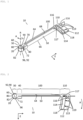
- the torque wrench 10 shown in the sequence of figures 1, 2 and 3 comprises a head region 30 having a receiving opening 20, a neck region 40 adjoining the head region 30, and a rod-shaped, rectangular in cross-section, bendable actuating lever 50 fastened to the neck region 40 for applying a torque on the head area 30.
- the receiving opening 20 of the head area 30 is formed by an annular enclosure 60, which has a Rotation axis R defined.
- the enclosure 60 is intended to accommodate an insertion instrument 62 in the extension of the axis of rotation R, which in Fig. 4 is described in more detail.
- a plane E extends perpendicular to the axis of rotation R and includes a front side 64 of the torque wrench 10, which front side 64 in Fig. 2 is shown.
- a back side 66 of the torque wrench 10 is in Fig. 3 pictured.
- a front side 68 of the operating lever 50 extends in the plane E. Furthermore, the extent of the cross section of the operating lever 50 is greater in the direction perpendicular to the plane E than in the direction parallel to the plane E.
- the neck region 40 forms an at least approximately cuboid-shaped, solid part and includes an incision 70 running at right angles to the plane E for receiving an end region of the actuating lever 50 and fastening it.
- the enclosure 60 has an opening 72 extending over its entire cross section and the enclosure 60 forms a spring clip 80.
- the spring clip 80 is formed on the side of the neck region 40 facing away from the actuating lever 50, protruding from it, integrally and in one piece with the neck region 40.
- the opening 72 borders on the neck region 40 and is formed by a slot 72 which extends at least approximately radially to the axis of rotation R.
- a section 82 of the spring clip 80 has a reduced cross section, which in the Fig. 5 is described in more detail.
- a locking lug 90 is formed on the spring clip 80, integrally and in one piece with the spring clip 80, adjacent to the opening. In its rest position, the locking lug 90 projects into the receiving opening 20. The rest position is the position of the locking lug 90 when no insertion instrument is inserted into the receiving opening 20 and no force is exerted in the radial direction on the spring clip 80.
- the locking lug 90 has a driving section 92, which is intended to, when the insertion instrument 62 is inserted into the receiving opening 20, when the actuating lever 50 is rotated in the tightening direction A in a driving position of the locking lug 90 with a counter surface 94 of the insertion instrument 62, which is on Fig. 4 and 5 can be seen to work together.
- the driving section 92 interacts with the counter surface 62, a torque is transmitted to the insertion instrument 62 through a positive driving force.
- the locking lug 90 is intended to move in the radial direction outwards into a release position when rotating against the tightening direction A, against the force of the spring clip 80, in order to form a freewheel between the head area 30 and the insertion instrument 62.
- the spring clip 80 has a side facing the rotation axis R in the tightening direction A, seen with respect to the driving surface 92, a semicircular recess 96 leading to the driving surface 92 and adjoining the driving surface 92.
- the torque wrench 10 also includes a bend-resistant shaft region 100 which projects from the neck region 40 on the side of the neck region 40 facing away from the head region 30 and extends in a bend-resistant shaft region 100 which extends at least approximately parallel to the plane E, and an indicator region 110 which projects from the free end region of the shaft region 100, wherein the actuating lever 50 extends beyond the indicator area 110.
- the shaft region 100 is, seen in the tightening direction A, attached to the neck region 40 downstream of the actuating lever 50, formed in one piece and integrally with the neck region 40 and runs parallel to the actuating lever 50 which is in its rest position, with a gap between the shaft region 100 and the Actuating lever 50 is present.
- the indicator area 110 extends in the form of a plate 112, which has a front surface 113 extending in the plane E, and is formed in one piece and integrally with the shaft area 100.
- the actuating lever 50 includes a recess 116 on its section overlapping the indicator area 110, which forms a free space 116 for the indicator area 110.
- the free space 116 is designed in such a way that it supports the movement of the front side 68 of the actuating lever 50 in the plane E, ie in the same plane as the front surface 113 of the plate 112 Actuation of the operating lever 50 is permitted.
- the recess 116 is formed by two rectangular incisions, the height of which, measured in the direction perpendicular to the plane E, at least approximately corresponds to the thickness of the plate 112, and which are separated from a section of the actuating lever 50 running in the plane E.
- the section of the actuating lever 50 forms a cam 117, which serves as a pointer 117 and moves into an elongated hole 114 formed in the plate 112 when the actuating lever 50 is actuated.
- the cam 117 is thus aligned with the front surface 113 of the indicator area 110.
- the elongated hole 114 extends in the form of a circular arc, the center of which is defined over the center of curvature of the actuated actuating lever 50.
- the pointer 117 moves along the elongated hole 114.
- the elongated hole 114 is designed such that it forms an end stop 118 for the cam 117 when the actuating lever 50 is bent corresponds to the maximum torque to be applied.
- measurement markings 119 are attached along the elongated hole 114, on which the deflection of the actuating lever 50 can be read as the generated torque.
- torques in the range of 10 Ncm to 100 Ncm are typically required.
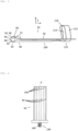
- Fig. 4 shows a conventional insertion instrument 62 comprising a cylindrical ratchet head 120 which defines an axis of rotation D of the insertion instrument and which can be inserted into the receiving opening 20 of the torque wrench 10, and a shaft 130 which adjoins the ratchet head 120 and extends in the direction of the axis of rotation D.
- the free End 140 of the shaft has a standardized profile for interacting with an implant or a connecting element, so that the insertion instrument 62 can transmit the torque applied to the ratchet head 120 to the implant or the connecting element.
- the ratchet head 120 has a peripheral surface 150, which includes a contouring forming the counter surface 94 in order to enable the torque applied to the torque wrench 10 to be transmitted to the insertion instrument 62.
- the contouring comprises a plurality of grooves 160 running parallel to the axis of rotation D of the insertion instrument 62, which are of the same design and, viewed in the circumferential direction, are arranged at the same distance from one another.
- the grooves 160 have an at least approximately rectangular cross section, the wall 94 of which runs in the tightening direction with respect to the driving surface, preferably at least approximately radially in the direction of the axis of rotation D and forms the counter surface 94.
- Fig. 5 the interaction of the driving section 92 of the locking lug 90 with the counter surface 94 of the inserted insertion instrument 62 is shown in the tightening direction A.
- the Driving section 92 is formed by the driving surface 92, which runs at least approximately radially to the axis of rotation R, which is intended to interact with the counter surface 94 of the insertion instrument 62 used, which runs at least approximately radially to the axis of rotation R.
- the working length L corresponds to the minimum length of the required movement of the locking lug 90, radially outwards with respect to the axis of rotation R, so that the locking lug 90 can reach its release position.
- the locking lug 90 has an engagement surface 170, viewed in the tightening direction A, which follows the driving surface 92 and adjoins the driving surface 92, which allows the locking lug 90 to move into the release position.
- the contact surface 170 is formed by a bevel 172, the distance from the axis of rotation R increases without interruption in the opposite direction to the tightening direction A and which allows freewheeling.
- the bevel 172 extends at least approximately to the free end 174 of the spring clip 80.
- the engagement surface 170 includes an extension surface 176 running in the circumferential direction, which directly adjoins the driving surface 92 and to which the bevel 172 directly adjoins.
- the locking lug 90 is designed such that, measured in the circumferential direction of the enclosure 60, the total length of the bevel 172 together with the extension surface 176 is longer than the width of the grooves 160.
- An angle W measured in the plane E between the bevel 172 and a tangent T1 to the circumferential direction running at the end point of the bevel, seen in the tightening direction, is approximately 30 ° in the illustrated embodiment.
- the spring clip 80 has at least approximately the smallest cross section at a point P1, measured in the radial direction.
- the point P1 is offset from the contact surface 170 at least approximately 90° in the tightening direction.
- the section 82 of the spring clip 80 with the reduced cross section extends on both sides of the point P1 in the illustrated embodiment.
- FIG. 6 A further embodiment of the opening 72 is shown, which is formed by a radially extending cut.
- the enclosure 60 has a thin wall, ie a longitudinal section, which is significantly larger in the axial direction than in the radial direction.
- the opening 72 is designed in such a way that it limits the movement of the spring clip 80 relative to the neck region 40 in the circumferential direction in the tightening direction A and against the tightening direction A.
- the spring clip 80 has on its free end 174 an end face 175 defined by the opening 72 and extending at least approximately radially to the axis of rotation R, which faces a counter end face 177 of the neck region 40 defined by the opening 72 and extending at least approximately radially to the axis of rotation.
- the opening 72 and thus the end face 175 and the counter end face 177 run, as seen in the longitudinal section of the enclosure 60, at least approximately S-shaped and from the front 64 to the back 66 of the torque wrench 10, with a first half facing the front 64 of the S-shape a first hook 178 projecting from the neck area 40 and a second half of the S-shape facing the back 66 form the second hook 180 projecting from the spring clip 80.
- a gap 182 between the first and second hooks 178 and 180 is present when the torque wrench is at rest and during normal operation.
- the first and second hooks 178 and 180 have a first and second projection 179 and 181, respectively, which come into contact when the deformation of the spring clip 80 has reached a predetermined level, and thus prevent further deformation of the spring clip 80. It should also be mentioned that deformation in the tightening direction as well as against the tightening direction can be prevented.
- FIG. 7 A further embodiment of the opening 72 is shown, which is formed by an axially extending cut.
- the enclosure 60 has a thick wall.
- the opening 72 seen in the cross section of the enclosure 60, i.e. in a plane running parallel to the plane E, runs at least approximately S-shaped and from an inside 184 of the enclosure 60 facing the axis of rotation to an outside 186 of the enclosure 60 facing away from the axis of rotation
- the first half of the S-shape facing the inside 184 forms the first hook 178 projecting from the neck region 40 and the second half of the S-shape facing the outside 186 forms the second hook 180 projecting from the spring clip 80.
- FIG. 8 A further embodiment of the opening 72 is shown, in which the opening 72 opens into a rectangular recess 188 formed in the neck region 40 and connected to the receiving opening 20.
- the recess 188 has a wall 190 which is directed at least approximately radially to the axis of rotation R and, as seen in the tightening direction A, trails the opening 72 and from which the second and a further projection 179 and 193 protrude in the direction of the interior of the recess 188.
- the second hook 180 comprises an arm 194 which projects radially outwards from the spring clip 80 with respect to the axis of rotation R and which extends into the recess 188 protrudes into it and lies between the second and the further projection 179 and 193 respectively.
- the free end of the arm 194 has the first projection 181 directed towards the wall 190.
- the first projection 181 comes into contact with the second projection 179 to limit the movement of the spring clip 80 by expansion when the deformation of the spring clip 80 has reached a predetermined level. In this way, over-expansion of the spring clip 80 can be prevented.
- the first projection 181 comes into contact with the further projection 193 in order to limit the movement of the spring clip 80 through compression.
- the first hook 178 may have a projection and the second hook 180 may have two projections.
- the interaction of the first and second hooks 178 and 180 and their respective projections when the spring clip 80 is deformed is the same as in the embodiment of Fig. 8 .
Landscapes
- Health & Medical Sciences (AREA)
- Engineering & Computer Science (AREA)
- Mechanical Engineering (AREA)
- Orthopedic Medicine & Surgery (AREA)
- Life Sciences & Earth Sciences (AREA)
- General Health & Medical Sciences (AREA)
- Veterinary Medicine (AREA)
- Public Health (AREA)
- Animal Behavior & Ethology (AREA)
- Dentistry (AREA)
- Epidemiology (AREA)
- Oral & Maxillofacial Surgery (AREA)
- Surgery (AREA)
- Nuclear Medicine, Radiotherapy & Molecular Imaging (AREA)
- Biomedical Technology (AREA)
- Heart & Thoracic Surgery (AREA)
- Medical Informatics (AREA)
- Molecular Biology (AREA)
- Dental Prosthetics (AREA)
- Details Of Spanners, Wrenches, And Screw Drivers And Accessories (AREA)
- Dental Tools And Instruments Or Auxiliary Dental Instruments (AREA)
Abstract
Description
- Die Erfindung betrifft einen Drehmomentschlüssel als Ratscheninstrument für die Medizinaltechnik, insbesondere die Dentalmedizin, gemäss dem Oberbegriff des Anspruchs 1.
- Aus der Dentalmedizin ist bekannt, Implantate in den Kieferknochen einzusetzen und an den Implantaten Verbindungselemente, wie Abutments, zu befestigen, auf welchen dann die Suprastruktur, insbesondere eine Krone oder eine Brücke, aufgesetzt wird. Zum Einschrauben des Implantats bzw. des Verbindungselements kann ein Eindrehinstrument auf dessen freies Ende formschlüssig aufgesetzt und das Eindrehinstrument über einen Drehmomentschlüssel gedreht werden. Langzeitstabilität und Zuverlässigkeit der Verschraubungen hängen davon ab, dass letztere mit dem jeweils optimalen Drehmoment ausgeführt werden. Ein zu schwaches Anziehen kann später zur Lockerung der Verschraubungen führen, während ein zu starkes Anziehen die eingesetzten Verbindungselemente und das Implantat überlastet und deren Bruchgefahr erhöht bzw. Schäden am Knochen verursacht.
- Ein Drehmomentschlüssel mit einer Ratschenfunktion zur Anwendung in der Dentalmedizin ist in der
EP 0 704 281 A1 offenbart. Der Drehmomentschlüssel umfasst ein Drehmomentinstrument, insbesondere ein Ratscheninstrument, sowie einen daran als Zubehör ansetzbaren Drehmomentindikator. Der Drehmomentindikator besitzt einen hülsenförmigen, auf einen Griff des Drehmomentinstruments aufschiebbaren Träger, an dem ein elastischer Biegestab befestigt ist. Auf das freie Ende des Biegestabes wird bei Betätigung eine Kraft in Anzugsrichtung des Drehmomentschlüssels ausgeübt und das erzeugte Drehmoment an einer Masseinteilung angezeigt. Die Reinigung und die Sterilisation dieses Drehmomentschlüssels erfordern eine Demontage des Drehmomentschlüssels und sind somit relativ aufwendig. Ferner ist seine Herstellung aufgrund der Vielzahl der Bauteile relativ teuer. - Aus der
DE 20 2004 014 195 U1 ist ein Drehmomentschlüssel als Ratscheninstrument für die Medizinaltechnik bekannt, welcher einen zuvorderst liegenden Kopfbereich, einen anschliessenden Halsbereich, dem ein Schaftbereich folgt, und einen zuhinterst angeordneten Griffbereich umfasst. Der Kopfbereich, der Halsbereich, der Schaftbereich und der Griffbereich erstrecken sich in einer Ebene. Der Drehmomentschlüssel umfasst ferner eine im Kopfbereich vorgesehene Aufnahmeöffnung, die von einer Umfassung umgeben ist und einen Mittelpunkt besitzt, durch den sich eine Achse senkrecht zur Ebene erstreckt. Die Aufnahmeöffnung dient zum Einsetzen eines Eindrehinstruments in der Erstreckung der Achse. Weiter umfasst der Drehmomentschlüssel ein an der Peripherie der Aufnahmeöffnung angeordnetes, begrenzt bewegliches Klinkensegment, dessen Frontpartie zur Aufnahmeöffnung weist. Die Frontpartie ist dazu bestimmt, bei Betätigung des Drehmomentschlüssels im Einschraubmodus, mit einer am Kopf des Eindrehinstruments vorhandenen Aussenkontur in mitnehmenden Eingriff zu kommen, und bei Betätigung des Drehmomentschlüssels in Rückwärtsrichtung, also im Ratschenmodus, den mitnehmenden Eingriff mit der am Kopf des Eindrehinstruments vorhandenen Aussenkontur zu lösen. Weiter umfasst der Drehmomentschlüssel einen vom Halsbereich längs des Schaftbereichs verlaufenden, biegesteifen Basisast. Vom Klinkensegment erstreckt sich eine Klinkenfeder in den Halsbereich hinein, wobei Klinkensegment und Klinkenfeder eine einstückige Klinke bilden. Beiderseits der Klinke sind lange dünne Schlitze ausgebildet, welche die Auslenkung der Klinke in der Ebene gegen die Kraft der Klinkenfeder erlauben. Ferner ist die Klinke einstückig aus dem Halsbereich herausgeformt. Durch die einteilige Ausführung dieses Drehmomentschlüssels fällt die Demontage bei der Reinigung und Sterilisation weg. Allerdings erschweren die langen dünnen Schlitze beiderseits der Klinke die Reinigung des Drehmomentschlüssels. - Aufgabe der vorliegenden Erfindung ist es somit, einen Drehmomentschlüssel für die Medizinaltechnik, insbesondere für die Dentalmedizin, zur Verfügung zu stellen, welche günstig herstellt und einfach gereinigt werden kann.
- Diese Aufgabe wird erfindungsgemäss durch ein Drehmomentschlüssel gemäss Anspruch 1 gelöst. Bevorzugte Ausführungsformen der Erfindung sind in den abhängigen Ansprüchen wiedergegeben.
- Die Erfindung betrifft einen Drehmomentschlüssel als Ratscheninstrument für die Medizinaltechnik, insbesondere die Dentalmedizin. Der Drehmomentschlüssel umfasst einen eine Aufnahmeöffnung aufweisenden Kopfbereich, einen an den Kopfbereich anschliessenden Halsbereich, einen am Halsbereich befestigten, sich wenigstens annähernd in einer Ebene, vorzugsweise in der Ebene erstreckenden, stabförmigen Betätigungshebel zum Aufbringen eines Drehmoments auf den Kopfbereich, und eine die Aufnahmeöffnung des Kopfbereichs bildende Umfassung. Der Halsbereich bildet ein wenigstens annähernd quaderförmiges, vorzugsweise massives Teil. Die Umfassung definiert eine wenigstens annähernd rechtwinklig, vorzugsweise rechtwinklig zur Ebene verlaufende Rotationsachse und ist dazu bestimmt, ein Eindrehinstrument in der Erstreckung der Rotationsachse aufzunehmen. Die Ebene kann eine Vorderseite des Drehmomentschlüssels und eine parallel zur Ebene verlaufende weitere Ebene kann eine Rückseite des Drehmomentschlüssels umfassen.
- Ferner umfasst der Drehmomentschlüssel einen Federbügel, und eine an diesem ausgebildeten Rastnase, welche in ihrer Ruhestellung in die Aufnahmeöffnung hineinragt. Die Ruhestellung ist die Position der Rastnase, wenn kein Eindrehinstrument in die Aufnahmeöffnung eingesetzt ist und keine Kraft in radialer Richtung auf den Federbügel ausgeübt wird.
- Die Rastnase weist einen Mitnahmeabschnitt auf, welcher dazu bestimmt ist, bei in die Aufnahmeöffnung eingesetztem Eindrehinstrument, bei einer Drehung in Anzugsrichtung des Betätigungshebels in einer Mitnahmestellung der Rastnase mit einer Gegenfläche des Eindrehinstruments zusammenzuwirken. Die Mitnahmestellung kann der Ruhestellung entsprechen, wenn der Federbügel wenigstens annähernd keine Kraft gegen das eingesetzte Eindrehinstrument ausübt. Beim Zusammenwirken des Mitnahmeabschnitts mit der Gegenfläche wird ein Drehmoment durch eine formschlüssige Mitnahme ans Eindrehinstrument übertragen.
- Die Rastnase ist dazu bestimmt, bei einer Drehung entgegen der Anzugsrichtung, gegen die Kraft des Federbügels sich in radialer Richtung gegen aussen in eine Freigabestellung zu bewegen, um einen Freilauf zwischen dem Kopfbereich und dem Eindrehinstrument zu bilden.
- Erfindungsgemäss weist die Umfassung eine über ihren gesamten Querschnitt verlaufende Durchbrechung auf und bildet die Umfassung den Federbügel.
- In einer bevorzugten Ausführungsform ist die Rastnase integral und einstückig mit dem Federbügel ausgebildet. Dies vereinfacht die Reinigung, weil eine Schmutzablagerung an einer Verbindungsstelle zwischen der Rastnase und dem Federbügel verhindert wird.
- In einer bevorzugten Ausführungsform ist der Mitnahmeabschnitt durch eine wenigstens annähernd radial zur Rotationsachse verlaufende Mitnahmefläche gebildet, welche dazu bestimmt ist, mit der vorzugsweise wenigstens annähernd radial zur Rotationsachse verlaufenden Gegenfläche des eingesetzten Eindrehinstruments zusammenzuwirken. Diese Ausbildung der Mitnahmefläche und der Gegenfläche ermöglicht eine sichere Mitnahme des Eindrehinstruments.
- Ferner kann die radial zur Rotationsachse gemessene Länge der Mitnahmefläche, welche Mitnahmefläche in Kontakt mit der Gegenfläche des Eindrehinstruments kommt, hier als Arbeitslänge bezeichnet, ebenfalls als Parameter verwendet werden, um eine sichere Mitnahme des Eindrehinstruments zu gewährleisten. Die Arbeitslänge entspricht der Länge der benötigten Bewegung der Rastnase, bezüglich der Rotationsachse radial nach aussen, sodass die Rastnase ihre Freigabestellung erreichen kann. Eine kurze Arbeitslänge kann folglich von Vorteil sein, weil die resultierende Verformung des Federbügels entsprechend klein ist und somit bleibt die Verformung im elastischen Bereich des Federbügels. Bei der Verwendung des Drehmomentschlüssels kann jedoch eine zu kurze Arbeitslänge dazu führen, dass der Mitnahmeabschnitt wegen einer unerwünschten Bewegung des Drehmomentschlüssels bezüglich des Eindrehinstruments auf die Gegenfläche um die Arbeitslänge bezüglich der Rotationsachse radial nach aussen rutscht, und folglich, dass die Rastnase aus der Mitnahmestellung ausrastet. Vorzugsweise ist die radiale Länge der Mitnahmefläche grösser als oder gleich wie die radiale Länge der Gegenfläche, um die Kraftübertragung zu optimieren. Vorzugsweise bewegt sich die radiale Länge der Mitnahmefläche zwischen 0,2 mm und 5 mm, um die Kraftübertragung zu optimieren.
- In einer bevorzugten Ausführungsform grenzt die Rastnase an die Durchbrechung an. Besonders bevorzugt grenzt die Rastnase an die Durchbrechung direkt an. Somit ist der Umschlingungswinkel des vorliegenden Federbügels um das eingesetzte Eindrehinstrument herum maximiert. Durch die Umschlingung entstehen zusätzlich Haftreibungskräfte in Umfangsrichtung zwischen dem Federbügel und dem eingesetzten Eindrehinstrument, die das Halten des Eindrehinstruments in die Aufnahmeöffnung unterstützen. Dies bewirkt, dass die in Umfangsrichtung auf den Mitnahmeabschnitt der Rastnase wirkende Kraft beim Drehen in Anzugsrichtung kleiner ist.
- In einer bevorzugten Ausführungsform weist die Rastnase eine, in Anzugsrichtung gesehen, der Mitnahmefläche nachlaufende, vorzugsweise an die Mitnahmefläche anschliessende Angriffsfläche auf, welche die Bewegung der Rastnase in die Freigabestellung und folglich den Freilauf erlaubt. Bei der Drehung des Betätigungshebels entgegen der Anzugsrichtung bildet die Angriffsfläche die Fläche, über welche die Kraft des Federbügels auf das Eindrehinstrument ausgeübt wird.
- Besonders bevorzugt ist die Angriffsfläche durch eine Abschrägung gebildet, deren Abstand zur Rotationsachse entgegen der Anzugsrichtung zunimmt und welche den Freilauf erlaubt. Vorzugsweise nimmt der Abstand ohne Unterbrechung zu, um einen kontinuierlichen, eine gleichbleibende Reibung der Angriffsfläche auf das Eindrehinstrument aufweisenden Freilauf zu ermöglichen. Somit erfüllt der Drehmomentschlüssel ruckfrei seine Ratschenfunktion.
- In einer besonders bevorzugten Ausführungsform erstreckt sich die Abschrägung mindestens annähernd bis zum freien Ende des Federbügels. Dies ermöglicht eine einfache Herstellung der der Rotationsache zugewandten Umfangsfläche des Federbügels.
- Besonders bevorzugt weist die Angriffsfläche eine, in Anzugsrichtung gesehen, der Mitnahmefläche nachlaufende, in Umfangsrichtung verlaufende Verlängerungsfläche auf, welche an die Mitnahmefläche direkt anschliesst, und an welche Verlängerungsfläche die Abschrägung anschliesst. Die Verlängerungsfläche und die Abschrägung begrenzen ein Volumen der Rastnase, welches dazu dient, die Abscherung des Mitnahmeabschnitts im Anwendungsfall zu verhindern. Durch dieses Volumen kann gegebenenfalls der Verschleiss des Eindrehinstruments durch die Rastnase beim Freilauf reduziert werden, weil die Rastnase keine scharfe Kante, zwischen der Mitnahmefläche und der Abschrägung aufweist.
- In einer besonders bevorzugten Ausführungsform weist die Abschrägung eine Länge, in radialer Richtung gemessen, gleich wie oder grösser als die Arbeitslänge. Dadurch wird vermieden, dass die Bewegung der Rastnase in die Freigabestellung bei der Drehung entgegen der Anzugsrichtung durch das Eindrehinstrument blockiert wird.
- In einer besonders bevorzugten Ausführungsform ist ein Winkel, in der Ebene E gemessen, zwischen der Abschrägung und einer Tangente zur Umfangsrichtung, wobei die Tangente an der Schnittstelle der Abschrägung und der Umfangsrichtung verläuft, kleiner als 45°, bevorzugt zwischen 15° und 45°, besonders bevorzugt zwischen 25° und 40°. Der Winkel ist kleiner als 45°, sodass die Bewegung der Rastnase in die Freigabestellung bei der Drehung entgegen der Anzugsrichtung wenig Raum in radialer Richtung benötigt. Insbesondere im Mundbereich kann die Bewegung der Rastnase nämlich eingeschränkt sein. Die Reibungskraft zwischen der Oberfläche der Abschrägung und dem Eindrehinstrument liegt bei einem Winkel zwischen 15° und 45° in einem Bereich, in dem das durch Reibung ans Eindrehinstrument übertragene Drehmoment bei der Drehung entgegen der Anzugsrichtung, z.B. das Freilaufmoment, unter einem Lösedrehmoment des Implantats oder des Verbindungselements bleibt. Dies ist insbesondere wichtig bei der Implantation in Knochen, der instabil und fragil sein kann, womit das Lösedrehmoment klein sein sollte. Vorzugsweise ist das Freilaufmoment kleiner als 3Ncm. Erfahrungsgemäss ist ein Winkel zwischen 25° und 40° optimal, um das Freilaufmoment und gleichzeitig die radiale Bewegung der Rastnase in die Freigabestellung zu optimieren.
- In einer bevorzugten Ausführungsform erstreckt sich die Rastnase, in axialer Richtung gemessen, über die gesamte Dicke der Umfassung. Die Erstreckung in axialer Richtung der Rastnase ermöglicht eine sichere Mitnahme, da die Mitnahmefläche entsprechend grösser ausfällt. Es ist jedoch auch möglich, dass die Rastnase sich nur über einen Teil der gesamten Dicke erstreckt, vorzugsweise, in axialer Richtung gesehen, zentriert bezüglich der Dicke der Umfassung. Durch die zentrische Lage der Rastnase gibt es keine lateralen Biegemomente auf den Federbügel.
- Ein herkömmliches Eindrehinstrument umfasst einen zylindrischen, eine Drehachse des Eindrehinstruments definierenden Ratschenkopf, welcher in die Aufnahmeöffnung des Drehmomentschlüssels eingesetzt werden kann, und einen an den Ratschenkopf anschliessenden, sich in Richtung der Drehachse erstreckenden Schaft. Das freie Ende des Schaftes weist ein vorzugsweise standardisiertes Profil, beispielsweise einen Profil torx® oder einen sechskantigen Kopf, zum Zusammenwirken mit dem Implantat bzw. dem Verbindungselement auf, sodass das Eindrehinstrument das auf den Ratschenkopf aufgebrachte Drehmoment an das Implantat bzw. das Verbindungselement übertragen kann. Der Ratschenkopf weist eine Umfangsfläche auf, welche eine die Gegenfläche bildende Konturierung umfasst, um eine Übertragung des auf den Drehmomentschlüssel aufgebrachten Drehmoments an das Eindrehinstrument zu ermöglichen. Die Konturierung kann von einer vorzugsweise parallel zur Drehachse des Eindrehinstruments verlaufenden Nut gebildet sein.
- Vorzugsweise weist die Nut einen mindestens annähernd rechteckigen Querschnitt auf, deren in Anzugsrichtung bezüglich der Mitnahmefläche vorlaufende Wand bevorzugt wenigstens annähernd radial in Richtung zur Drehachse verläuft und die Gegenfläche bildet.
- Vorzugsweise umfasst die Konturierung eine Mehrzahl von Nuten, welche gleich ausgebildet und, in Umfangsrichtung gesehen, im gleichen Abstand zueinander angeordnet sind.
- In einer bevorzugten Ausführungsform des Drehmomentschlüssels ist die Rastnase so ausgebildet, dass, in Umfangsrichtung der Umfassung gemessen, die Gesamtlänge der Abschrägung gegebenenfalls zusammen mit der Verlängerungsfläche länger als die Breite der Nut ist. Somit kann das Einschieben der ganzen Rastnase in die Nut und die daraus resultierende mögliche Blockierung der Bewegung der Rastnase in die Freigabestellung bei einer Drehung entgegen der Anzugsrichtung wenigstens annähernd vollständig vermieden werden.
- In einer bevorzugten Ausführungsform weist der Federbügel auf seiner der Rotationsachse zugewandten Seite eine, in Anzugsrichtung gesehen, bezüglich der Mitnahmefläche vorlaufende, an die Mitnahmefläche anschliessende Ausnehmung auf. Vorzugsweise ist die Ausnehmung wenigstens annähernd halbkreisförmig. Ferner ist sie so ausgebildet, dass ein der Gegenfläche vorlaufende Teil des Ratschenkopfs in die Ausnehmung bei einer Drehung in Anzugsrichtung hineinragen kann. Somit wird eine sichere Mitnahme des Eindrehinstruments sichergestellt.
- In einer bevorzugten Ausführungsform grenzt die Durchbrechung an den Halsbereich an. Vorzugsweise ist die Durchbrechung durch einen sich wenigstens annähernd radial zur Rotationsachse erstreckenden Schlitz gebildet. Somit ist die Länge des Federbügels, in Umfangsrichtung gemessen, maximiert. Folglich ist der Umschlingungswinkel des Federbügels um das eingesetzte Eindrehinstrument herum in Anzugsrichtung maximiert. Die Durchbrechung ist derart ausgebildet, dass die Rastnase sich radial nach aussen bezüglich der Rotationsachse wenigstens um die Arbeitslänge bewegen kann, sodass sie ihre Freigabestellung erreichen kann.
- In einer bevorzugten Ausführungsform ist die Durchbrechung durch einen wenigstens annähernd radial verlaufenden Schnitt ausgebildet. Somit kann die Durchbrechung einfach ausgebildet werden, insbesondere bei einer Umfassung mit einer dünnen Wandung.
- In einer bevorzugten Ausführungsform ist die Durchbrechung durch einen wenigstens annähernd axial verlaufenden Schnitt ausgebildet. Bei einer Umfassung mit einer dickeren Wandung als in der vorherigen Ausführungsform kann die Durchbrechung ebenfalls einfach ausgebildet werden.
- In einer bevorzugten Ausführungsform kann die Durchbrechung derart ausgebildet sein, dass die Bewegung des Federbügels in Umfangsrichtung begrenzt ist.
- Der Federbügel weist auf seinem freien Ende eine durch die Durchbrechung definierte, wenigstens annähernd radial zur Rotationsachse verlaufende Stirnfläche auf, welche eine durch die Durchbrechung definierte, wenigstens annähernd radial zur Rotationsachse verlaufende Gegenstirnfläche des Halsbereichs zugewandt ist.
- In einer bevorzugten Ausführungsform ist die Breite der Durchbrechung, in Umfangsrichtung gemessen, derart bemessen, dass die Stirnfläche des Federbügels bei einer Verformung durch eine Kompression mindestens teilweise in Anlage mit der Gegenstirnfläche des Halsbereichs kommen kann, wenn die Verformung des Federbügels ein vorbestimmtes Mass erreicht hat. Die Breite der Durchbrechung wird derart bestimmt, dass die Verformung des Federbügels in dessen elastischen Bereich bleibt. Somit kann eine weitere Verformung des Federbügels und folglich eine Beschädigung des Drehmomentschlüssels verhindert werden.
- Besonders bevorzugt bildet die Durchbrechung einen vom Halsbereich abstehenden, ersten Haken und einen vom Federbügel abstehenden, zweiten Haken. Der erste und der zweite Haken weisen einen ersten und einen zweiten Vorsprung auf, welche quer, vorzugsweise rechtwinklig zur Anzugsrichtung verlaufen und sich überlappen. Im Ruhezustand und beim normalen Betrieb des Drehmomentschlüssels sind der erste und der zweite Vorsprung voneinander beabstandet. Das heisst, dass der erste und der zweite Vorsprung so ausgebildet sind, dass ein Spalt zwischen letzteren im Ruhezustand und im normalen Betrieb vorhanden ist.
- Um eine Überdehnung des Federbügels zu vermeiden kommen der erste und der zweite Vorsprung in Anlage, wenn die Verformung des Federbügels durch eine Ausdehnung ein vorbestimmtes Mass erreicht hat. Somit kann eine weitere Verformung des Federbügels und folglich eine Beschädigung des Drehmomentschlüssels verhindert werden. Eine Überdehnung kann beispielsweise beim Greifen und Herausnehmen des Drehmomentschlüssels aus einer Chirurgiekassette erfolgen, wenn zum Beispiel der Drehmomentschlüssel und andere Werkzeuge ineinandergreifen und am Drehmomentschlüssel zu fest gezogen wird.
- Der Spalt wird derart bestimmt, dass die Verformung des Federbügels in dessen elastischen Bereich bleibt. Dies bedeutet, dass die Verformung reversible bleibt und der Federbügel seine ursprüngliche Form wieder aufnimmt, wenn keine Verformungskraft mehr aufgebracht wird. Somit kann sichergestellt werden, dass der Federbügel seine Eigenschaften beibehält, insbesondere die ausgeübte Kraft, gegen die die Rastnase in die Freigabestellung gelangen kann.
- Wenn der Aussendurchmesser des Ratschenkopfs des eingesetzten Eindrehinstruments kleiner als der Innendurchmesser der Aufnahmeöffnung ist, kann der Spalt im normalen Betrieb kleiner als im Ruhezustand sein.
- Die durch den wenigstens annähernd radial verlaufenden Schnitt ausgebildete Durchbrechung kann, in Längsschnitt der Umfassung gesehen, wenigstens annähernd S-förmig und von der Vorderseite zur Rückseite des Drehmomentschlüssels verlaufen, wobei eine der Vorderseite zugewandte erste Hälfte der S-Form den ersten Haken und eine der Rückseite zugewandte zweite Hälfte der S-Form den zweiten Haken bilden.
- Möglich ist ebenfalls, dass die durch den wenigstens annähernd axial verlaufenden Schnitt ausgebildete Durchbrechung, im Querschnitt der Umfassung gesehen, wenigstens annähernd S-förmig und von einer der Rotationsachse zugewandten Innenseite der Umfassung zu einer der Rotationsachse abgewandten Aussenseite der Umfassung verläuft. In dieser Ausführungsform bildet die der Innenseite zugewandte erste Hälfte der S-Form den ersten Haken und eine der Aussenseite zugewandte erste Hälfte der S-Form bildet den zweiten Haken.
- In einer bevorzugten Ausführungsform mündet die Durchbrechung in eine im Halsbereich ausgebildete Aussparung, welche den ersten Haken aufweist. Ferner ragt der vom Federbügel abstehende, zweite Haken in die Aussparung hinein, um mit dem ersten Haken in Eingriff zu kommen, wenn die Verformung des Federbügels durch eine Kompression oder eine Ausdehnung ein vorbestimmtes Mass erreicht hat. Dadurch dass der Eingriff des ersten und des zweiten Hakens eine weitere Bewegung des Federbügels bezüglich des Halsbereichs verhindern, kann eine weitere Verformung des Federbügels und folglich eine Beschädigung des Drehmomentschlüssels verhindert werden.
- In einer bevorzugten Ausführungsform des Drehmomentschlüssels ist der Federbügel auf der dem Betätigungshebel abgewandten Seite des Halsbereichs von diesem abstehend ausgebildet. Diese Anordnung ermöglicht eine einfache Handhabung des Drehmomentschlüssels beim Einsatz im Mund des Patienten.
- Bevorzugt ist der Federbügel integral und einstückig mit dem Halsbereich ausgebildet. Dies vereinfacht die Reinigung, da die Abwesenheit einer Verbindungsstelle zwischen dem Halsbereich und dem Federbügel eine Schmutzablagerung an der Verbindungsstelle verhindert.
- In einer bevorzugten Ausführungsform des Drehmomentschlüssels weist ein Abschnitt des Federbügels einen reduzierten Querschnitt auf, um die wenigstens annähernd in radialer Richtung vom Federbügel auf das eingesetzte Eindrehinstrument ausgeübte Kraft zu dimensionieren. Diese Konstruktion ist einfach in die Herstellung des Drehmomentschlüssels umsetzbar und bildet eine günstige Variante zum Erreichen der erwünschten Kraft des Federbügels. Die Reduktion des Querschnitts des Federbügels zielt darauf ab, die Kraft des Federbügels zu reduzieren, sodass das ans Eindrehinstrument durch Reibung übertragene Drehmoment in der Freigabestellung der Rastnase minimal ist. Dadurch kann ein unerwünschtes Losschrauben des Implantats oder des Verbindungselements in die Freigabestellung vermieden werden.
- Der Abschnitt des Federbügels mit dem reduzierten Querschnitt kann durch eine Aussparung im Federbügel gebildet sein. Beispielsweise kann diese Aussparung durch einen radial zur Rotationsachse verlaufenden Einschnitt im Federbügel gebildet sein. Bei gleichem Material für den Federbügel ist es jedoch auch möglich, einen über die gesamte Länge des Federbügels konstanten jedoch dünneren Querschnitt des Federbügels zu wählen, um dieselbe ausgeübte Kraft zu erreichen. Die Bestimmung der Kraft des Federbügels ist in diesem Fall einfach, jedoch kann der dünne Querschnitt eine Schwachstelle für bestimmte Materialien bilden. Ferner ist es auch möglich die ausgeübte Kraft des Federbügels durch die Wahl eines passenden Materials zu dimensionieren. Je nach zu erfüllenden Bedingungen bei der Dimensionierung der Kraft des Federbügels kann der Fachmann eine der oben erwähnten Lösung wählen oder diese Lösungen kombinieren.
- In einer bevorzugten Ausführungsform des Drehmomentschlüssels ist die Umfassung wenigstens annähernd kreisringförmig ausgebildet. Diese Form der Umfassung passt zu einer Mehrheit der Eindrehinstrumente, sodass der Drehmomentschlüssel breit eingesetzt werden kann. Ferner kann diese Form einfach und günstig hergestellt werden.
- In einer besonders bevorzugten Ausführungsform des Drehmomentschlüssels mit einer wenigstens annähernd kreisringförmigen Umfassung, erstreckt sich eine Tangente zu der der Rotationsache zugewandten Umfangsfläche des Federbügels an einem Punkt des Abschnitts, an welchem, in radialer Richtung gemessen, der Federbügel den wenigstens annähernd kleinsten Querschnitt aufweist, wenigstens annähernd parallel zu einem Radius, welcher Radius von der Rotationsachse zum Mitnahmeabschnitt verläuft. Es ist jedoch auch möglich, die Tangente wenigstens annähernd parallel zu einer Normale bezüglich der Angriffsfläche, welche bevorzugt eine Ebene ist, zu gestalten. Diese Anordnungen bieten eine optimale Verteilung der Spannungen in der Umfassung, sodass das Risiko eines Bruchs oder einer nicht elastischen Verformung des Federbügels reduziert werden kann.
- Bei der Dimensionierung der durch den Federbügel auf das Eindrehinstrument, bei der Drehung entgegen der Anzugsrichtung ausgeübten Kraft muss sichergestellt werden, dass das übertragene Drehmoment, d.h. das in der Freigabestellung der Rastnase übertragene Drehmoment, einen vorbestimmten Drehmomentgrenzwert nicht überschreitet, welcher zu einem Ausschrauben des Implantats bzw. des Verbindungselements führen könnte. Somit kann der Drehmomentschlüssel seine Ratschenfunktion bei einer Drehung entgegen der Anzugsrichtung erfüllen.
- In einer bevorzugten Ausführungsform umfasst der Drehmomentschlüssel einen vom Halsbereich auf der dem Kopfbereich abgewandten Seite des Halsbereichs abstehenden, sich in einer wenigstens annähernd parallel zur Ebene erstreckenden Schaftbereich und einen vom freien Endbereich des Schaftbereichs abstehenden Indikatorbereich, wobei der Betätigungshebel sich mindestens bis zum Indikatorbereich erstreckt. Bevorzugt erstreckt sich der Betätigungshebel bis in den Indikatorbereich.
- Vorzugsweise ist der Betätigungshebel einstückig und integral mit dem Halsbereich ausgebildet, um die Reinigung zu vereinfachen.
- Besonders bevorzugt erstreckt sich der Betätigungshebel über den Indikatorbereich hinaus, um eine einfache Bedienung des Betätigungshebels über dessen dem Indikatorbereich hinausgehenden Abschnitt zu ermöglichen.
- Eine Ruheposition bzw. eine Auslenkposition des Betätigungshebels definiert seine Lage, wenn keine bzw. eine Kraft auf den Betätigungshebel ausgeübt wird, d.h. wenn der Betätigungshebel keine bzw. eine Biegung aufweist.
- Vorzugsweise ist der Schaftbereich, in Anzugsrichtung gesehen, abwärts des Betätigungshebels an dem Halsbereich befestigt und verläuft der Schaftbereich parallel zu dem sich in seiner Ruheposition befindenden Betätigungshebel. Diese Anordnung bietet eine kompakte Form des Drehmomentschlüssels, sodass der Drehmomentschlüssel wenig Platz in der Chirurgiekassette einnimmt. Ferner greifen der Drehmomentschlüssel und andere Werkzeuge somit in der Chirurgiekassette nicht ineinander.
- Vorzugsweise ist ein Spalt zwischen dem Schaftbereich und dem Betätigungshebel vorhanden, um eine einfache Reinigung zu ermöglichen.
- Vorzugsweise erstreckt sich der Indikatorbereich ebenfalls wenigstens annähernd parallel zur Ebene, beispielsweise in der Form eines Plättchens. Besonders bevorzugt ist der Indikatorbereich einstückig und integral mit dem Schaftbereich ausgebildet. Diese Ausführungsform ist konstruktiv besonders einfach und ihre Herstellung kostengünstig.
- Es ist ebenfalls möglich den Schaftbereich mit einem ersten und einem zweiten Arm auszubilden, welche sich wenigstens annähernd parallel zur Ebene und vom Halsbereich auf der dem Kopfbereich abgewandten Seite erstrecken, wobei das freie Ende des ersten und des zweiten Arms über den Indikatorbereich verbunden sind und der Betätigungshebel an den Halsbereich zwischen dem ersten und dem zweiten Arm angeordnet ist. Der erste und zweite Arm bilden zusammen mit dem Indikatorbereich einen Griff, vorzugsweise in der Form eines spitzwinkligen Dreiecks, welcher eine einfache Handhabung des Drehmomentschlüssels erlauben, insbesondere bei dessen Aufsetzen auf das Eindrehinstrument.
- Vorzugsweise ist der Schaftbereich biegefest, sodass die relative Bewegung des Betätigungshebels bezüglich des Schaftbereichs zuverlässig und einfach reproduziert werden kann.
- In einer besonders bevorzugten Ausführungsform des Drehmomentschlüssels ist der Betätigungshebel biegbar, vorzugsweise elastisch biegbar, besonders bevorzugt linearelastisch biegbar. Mit einem elastisch biegbaren Betätigungshebel wird sichergestellt, dass die Biegung reversible bleibt und der Betätigungshebel seine ursprüngliche Form wieder aufnimmt, wenn keine Kraft mehr aufgebracht wird. Somit kann die Anzeigegenauigkeit des aufgebrachten Drehmoments über die Lebensdauer des Drehmomentschlüssels gewährleistet sein. Ein linearelastisch biegbarer Betätigungshebel weist eine proportional zur einwirkenden Kraft resultierende Biegung auf, welche eine zuverlässige und praktische Bedienung des Drehmomentschlüssels ermöglicht.
- Bei der Aufbringung einer Kraft in Anzugsrichtung auf einen freien Endbereich des Betätigungshebels ist eine Auslenkung des Betätigungshebels ausgehend von dessen Ruheposition ein Mass für das generierte Drehmoment. Vorzugsweise umfasst der Betätigungshebel auf seinem dem Indikatorbereich überlappenden Abschnitt einen Nocken und umfasst der Indikatorbereich ein Langloch, welches dazu bestimmt ist, den Nocken aufzunehmen. Bei der Biegung des Betätigungshebels von seiner Ruheposition mindestens bis zu einer maximalen vorbestimmten Biegung bewegt sich der Nocken entlang des Langloches. Besonders bevorzugt ist das Langloch derart ausgebildet, dass es einen Endanschlag für den Nocken bildet, wenn die Biegung des Betätigungshebels dem maximalen aufzubringenden Drehmoment entspricht. Dadurch kann ein Überdehnen und somit eine Verformung ausserhalb des elastischen Bereichs des Betätigungshebels annähernd vollständig vermieden werden.
- In einer noch bevorzugteren Ausführungsform des Drehmomentschlüssels sind auf dem Indikatorbereich Messmarkierungen angebracht, an welchen die Auslenkung des Betätigungshebels als erzeugtes Drehmoment ablesbar ist.
- Vorzugsweise sind die Messmarkierungen entlang des Langlochs angebracht, sodass das aufgebrachte Drehmoment über die Position des Nockens im Langloch bezüglich den Messmarkierungen abgelesen werden kann. Vorzugsweise ist der Nocken fluchtend mit der Oberfläche des Indikatorbereichs ausgebildet, sodass ein Parallaxenfehler beim Auswerten der Übereinstimmung des Nockens mit einer Messmarkierung vermieden werden kann.
- Zur Herstellung des Drehmomentschlüssels sind Werkstoffe geeignet, welche bereits in der Medizinaltechnik eingesetzt werden und biokompatibel, reinigbar sowie sterilisierbar sind. Geeignete Materialien sind hierbei beispielsweise Metall und Metalllegierungen wie Stahl, rostfreier Stahl, Titan, Titanlegierungen und Kunststoff.
- Der Drehmomentschlüssel kann auch zum Lösen des Implantats bzw. des Verbindungselements gebraucht werden, indem der Drehmomentschlüssel um den Betätigungshebel um 180° gedreht wird und auf das Eindrehinstrument wieder aufgesetzt wird.
- Weitere Vorteile und Eigenschaften der Erfindung gehen aus der nachstehenden Beschreibung eines Ausführungsbeispiels hervor, welches anhand der beiliegenden Figuren erläutert wird.
- Diese zeigen rein schematisch:
- Fig. 1
- eine perspektivische Ansicht des erfindungsgemässen Drehmomentschlüssels;
- Fig. 2
- eine Draufsicht des Drehmomentschlüssels gemäss
Fig. 1 ; - Fig. 3
- eine Ansicht der Rückseite des Drehmomentschlüssels gemäss
Fig. 1 ; - Fig. 4
- eine Seitenansicht eines herkömmlichen Eindrehinstruments;
- Fig. 5
- eine Draufsicht des Kopfbereichs mit dem im Querschnitt dargestellten, eingesetzten Eindrehinstrument der
Fig. 4 ; - Fig. 6
- eine perspektivische Ansicht des Kopf- und Halsbereichs einer weiteren Ausführungsform des Drehmomentschlüssels;
Fig. 7 eine Draufsicht des Kopf- und Halsbereichs einer weiteren Ausführungsform des Drehmomentschlüssels; und - Fig. 8
- eine Draufsicht des Kopf- und Halsbereichs einer weiteren Ausführungsform des Drehmomentschlüssels.
- Der in der Figurenfolge 1, 2 und 3 abgebildete Drehmomentschlüssel 10 umfasst einen eine Aufnahmeöffnung 20 aufweisenden Kopfbereich 30, einen an den Kopfbereich 30 anschliessenden Halsbereich 40, und einen am Halsbereich 40 befestigten, stabförmigen, im Querschnitt rechteckförmigen, biegbaren Betätigungshebel 50 zum Aufbringen eines Drehmoments auf den Kopfbereich 30. Die Aufnahmeöffnung 20 des Kopfbereichs 30 ist durch eine kreisringförmige Umfassung 60 gebildet, welche eine Rotationsachse R definiert. Die Umfassung 60 ist dazu bestimmt, ein Eindrehinstrument 62 in der Erstreckung der Rotationsachse R aufzunehmen, welches in
Fig. 4 näher beschrieben wird. Eine Ebene E erstreckt sich rechtwinklig zur Rotationsachse R und umfasst eine Vorderseite 64 des Drehmomentschlüssels 10, welche Vorderseite 64 inFig. 2 dargestellt ist. Eine Rückseite 66 des Drehmomentschlüssels 10 ist inFig. 3 abgebildet. - Eine Vorderseite 68 des Betätigungshebels 50 erstreckt sich in der Ebene E. Ferner ist die Ausdehnung des Querschnitts des Betätigungshebels 50 grösser in Richtung rechtwinklig zur Ebene E als in Richtung parallel zur Ebene E.
- Der Halsbereich 40 bildet ein wenigstens annähernd quaderförmiges, massives Teil und umfasst einen sich rechtwinklig zur Ebene E verlaufenden Einschnitt 70 zur Aufnahme eines Endbereichs des Betätigungshebels 50 und dessen Befestigung.
- Weiter weist die Umfassung 60 eine über ihren gesamten Querschnitt verlaufende Durchbrechung 72 auf und bildet die Umfassung 60 einen Federbügel 80. Der Federbügel 80 ist auf der dem Betätigungshebel 50 abgewandten Seite des Halsbereichs 40 von diesem abstehend, integral und einstückig mit dem Halsbereich 40 ausgebildet. Die Durchbrechung 72 grenzt an den Halsbereich 40 an und ist durch einen sich wenigstens annähernd radial zur Rotationsachse R erstreckenden Schlitz 72 gebildet.
- Ein Abschnitt 82 des Federbügels 80 weist einen reduzierten Querschnitt auf, welcher in der
Fig. 5 näher beschrieben wird. - Eine Rastnase 90 ist an dem Federbügel 80, integral und einstückig mit dem Federbügel 80, an die Durchbrechung angrenzend ausgebildet. In ihrer Ruhestellung ragt die Rastnase 90 in die Aufnahmeöffnung 20 hinein. Die Ruhestellung ist die Position der Rastnase 90, wenn kein Eindrehinstrument in die Aufnahmeöffnung 20 eingesetzt ist und keine Kraft in radialer Richtung auf den Federbügel 80 ausgeübt wird.
- Ferner weist die Rastnase 90 einen Mitnahmeabschnitt 92 auf, welcher dazu bestimmt ist, bei in die Aufnahmeöffnung 20 eingesetztem Eindrehinstrument 62, bei einer Drehung in Anzugsrichtung A des Betätigungshebels 50 in einer Mitnahmestellung der Rastnase 90 mit einer Gegenfläche 94 des Eindrehinstruments 62, welches auf
Fig. 4 und5 ersichtlich ist, zusammenzuwirken. Beim Zusammenwirken des Mitnahmeabschnitts 92 mit der Gegenfläche 62 wird ein Drehmoment durch eine formschlüssige Mitnahme ans Eindrehinstrument 62 übertragen. - Die Rastnase 90 ist dazu bestimmt, bei einer Drehung entgegen der Anzugsrichtung A, gegen die Kraft des Federbügels 80 sich in radialer Richtung gegen aussen in eine Freigabestellung zu bewegen, um einen Freilauf zwischen dem Kopfbereich 30 und dem Eindrehinstrument 62 zu bilden.
- Zudem weist der Federbügel 80 auf seiner der Rotationsachse R zugewandten Seite eine, in Anzugsrichtung A gesehen, bezüglich der Mitnahmefläche 92 vorlaufende, an die Mitnahmefläche 92 anschliessende, halbkreisförmige Ausnehmung 96 auf.
- Der Drehmomentschlüssel 10 umfasst ebenfalls einen vom Halsbereich 40 auf der dem Kopfbereich 30 abgewandten Seite des Halsbereichs 40 abstehenden, sich in einer wenigstens annähernd parallel zur Ebene E erstreckenden, biegefesten Schaftbereich 100 und einen vom freien Endbereich des Schaftbereichs 100 abstehenden Indikatorbereich 110, wobei der Betätigungshebel 50 sich über den Indikatorbereich 110 hinaus erstreckt.
- Der Schaftbereich 100 ist, in Anzugsrichtung A gesehen, abwärts des Betätigungshebels 50 an dem Halsbereich 40 befestigt, einstückig und integral mit dem Halsbereich 40 ausgebildet und verläuft parallel zu dem sich in seiner Ruheposition befindenden Betätigungshebel 50, wobei ein Spalt zwischen dem Schaftbereich 100 und dem Betätigungshebel 50 vorhanden ist.
- Der Indikatorbereich 110 erstreckt sich in der Form eines Plättchens 112, welches eine in der Ebene E verlaufende Vorderfläche 113 aufweist, und ist einstückig und integral mit dem Schaftbereich 100 ausgebildet.
- Der Betätigungshebel 50 umfasst auf seinem dem Indikatorbereich 110 überlappenden Abschnitt eine Aussparung 116, welche einen Freiraum 116 für den Indikatorbereich 110 bildet. Der Freiraum 116 ist derart ausgebildet, dass er die Bewegung der Vorderseite 68 des Betätigungshebels 50 in der Ebene E, d.h. in derselben Ebene wie die Vorderfläche 113 des Plättchens 112, bei Betätigung des Betätigungshebels 50 erlaubt. Die Aussparung 116 ist durch zwei rechteckförmige Einschnitte gebildet, deren Höhe, in Richtung rechtwinklig zur Ebene E gemessen, der Dicke des Plättchens 112 wenigstens annähernd entspricht, und welche von einem in der Ebene E verlaufenden Abschnitt des Betätigungshebels 50 getrennt sind. Der Abschnitt des Betätigungshebels 50 bildet einen Nocken 117, welcher als Zeiger 117 dient und sich in ein im Plättchen 112 ausgebildetes Langloch 114 bei Betätigung des Betätigungshebels 50 bewegt. Der Nocken 117 ist somit fluchtend mit der Vorderfläche 113 des Indikatorbereichs 110 ausgebildet. Das Langloch 114 erstreckt sich in der Form eines Kreisbogens, dessen Mittelpunkt über den Krümmungsmittelpunkt des betätigten Betätigungshebels 50 definiert ist.
- Bei der Biegung des Betätigungshebels von seiner Ruheposition mindestens bis zu einer maximalen vorbestimmten Biegung bewegt sich der Zeiger 117 entlang des Langloches 114. Das Langloch 114 ist derart ausgebildet, dass es einen Endanschlag 118 für den Nocken 117 bildet, wenn die Biegung des Betätigungshebels 50 dem maximalen aufzubringenden Drehmoment entspricht.
- Auf dem Indikatorbereich 110 sind Messmarkierungen 119 entlang des Langlochs 114 angebracht, an welchen die Auslenkung des Betätigungshebels 50 als erzeugtes Drehmoment ablesbar ist. Bei der Aufbringung einer Kraft in Anzugsrichtung A auf einen freien Endbereich des Betätigungshebels 50 ist eine Auslenkung des Betätigungshebels 50 ausgehend von dessen Ruheposition ein Mass für das generierte Drehmoment.
- Je nach Zahnimplantatsystem sind Drehmomente im Bereich von 10 Ncm bis 100 Ncm typischerweise erforderlich.
-
Fig. 4 zeigt ein herkömmliches Eindrehinstrument 62 umfassend einen zylindrischen, eine Drehachse D des Eindrehinstruments definierenden Ratschenkopf 120, welcher in die Aufnahmeöffnung 20 des Drehmomentschlüssels 10 eingesetzt werden kann, und einen an den Ratschenkopf 120 anschliessenden, sich in Richtung der Drehachse D erstreckenden Schaft 130. Das freie Ende 140 des Schaftes weist ein standardisiertes Profil zum Zusammenwirken mit einem Implantat bzw. einem Verbindungselement auf, sodass das Eindrehinstrument 62 das auf den Ratschenkopf 120 aufgebrachte Drehmoment an das Implantat bzw. das Verbindungselement übertragen kann. Der Ratschenkopf 120 weist eine Umfangsfläche 150 auf, welche eine die Gegenfläche 94 bildende Konturierung umfasst, um eine Übertragung des auf den Drehmomentschlüssel 10 aufgebrachten Drehmoments an das Eindrehinstrument 62 zu ermöglichen. Die Konturierung umfasst eine Mehrzahl von parallel zur Drehachse D des Eindrehinstruments 62 verlaufenden Nuten 160, welche gleich ausgebildet und, in Umfangsrichtung gesehen, im gleichen Abstand zueinander angeordnet sind. Die Nuten 160 weisen einen mindestens annähernd rechteckigen Querschnitt auf, deren in Anzugsrichtung bezüglich der Mitnahmefläche vorlaufende Wand 94 bevorzugt wenigstens annähernd radial in Richtung zur Drehachse D verläuft und die Gegenfläche 94 bildet. - In
Fig. 5 ist die Zusammenwirkung des Mitnahmeabschnitts 92 der Rastnase 90 mit der Gegenfläche 94 des eingesetzten Eindrehinstruments 62 in Anzugsrichtung A dargestellt. Der Mitnahmeabschnitt 92 ist durch die wenigstens annähernd radial zur Rotationsachse R verlaufende Mitnahmefläche 92 gebildet, welche dazu bestimmt, mit der wenigstens annähernd radial zur Rotationsachse R verlaufenden Gegenfläche 94 des eingesetzten Eindrehinstruments 62 zusammenzuwirken. - Die radial zur Rotationsachse R gemessene Länge der Mitnahmefläche 92, welche in Kontakt mit der Gegenfläche 94 des Eindrehinstruments 62 kommt, bildet die Arbeitslänge L. Die Arbeitslänge L entspricht der minimalen Länge der benötigten Bewegung der Rastnase 90, bezüglich der Rotationsachse R radial nach aussen, sodass die Rastnase 90 ihre Freigabestellung erreichen kann.
- Weiter weist die Rastnase 90 eine, in Anzugsrichtung A gesehen, der Mitnahmefläche 92 nachlaufende, an die Mitnahmefläche 92 anschliessende Angriffsfläche 170 auf, welche die Bewegung der Rastnase 90 in die Freigabestellung erlaubt.
- Die Angriffsfläche 170 ist durch eine Abschrägung 172 gebildet, deren Abstand zur Rotationsachse R entgegen der Anzugsrichtung A ohne Unterbrechung zunimmt und welche den Freilauf erlaubt. Die Abschrägung 172 erstreckt sich mindestens annähernd bis zum freien Ende 174 des Federbügels 80.
- Zudem umfasst die Angriffsfläche 170 eine in Umfangsrichtung verlaufende Verlängerungsfläche 176, welche an die Mitnahmefläche 92 direkt anschliesst und an welche die Abschrägung 172 direkt anschliesst.
- Die Rastnase 90 ist so ausgebildet, dass, in Umfangsrichtung der Umfassung 60 gemessen, die Gesamtlänge der Abschrägung 172 zusammen mit der Verlängerungsfläche 176 länger als die Breite der Nuten 160 ist.
- Ein in der Ebene E gemessener Winkel W zwischen der Abschrägung 172 und einer an dem, in Anzugsrichtung gesehen, nachlaufenden Endpunkt der Abschrägung verlaufenden Tangente T1 zur Umfangsrichtung beträgt in der dargestellten Ausführungsform ca. 30°.
- Der Federbügel 80 weist an einem Punkt P1, in radialer Richtung gemessen, den wenigstens annähernd kleinsten Querschnitt auf. Der Punkt P1 befindet sich gegenüber der Angriffsfläche 170 wenigstens annähernd um 90° in Anzugsrichtung versetzt. Der Abschnitt 82 des Federbügels 80 mit dem reduzierten Querschnitt erstreckt sich beiderseits des Punktes P1 in der dargestellten Ausführungsform.
- In
Fig. 6 ist eine weitere Ausführungsform der Durchbrechung 72 dargestellt, welche durch einen radial verlaufenden Schnitt ausgebildet ist. Die Umfassung 60 weist eine dünne Wandung auf, d.h. einen Längsschnitt, welcher wesentlich grösser in axialer Richtung als in radialer Richtung ist. - Die Durchbrechung 72 ist derart ausgebildet, dass sie die Bewegung des Federbügels 80 gegenüber dem Halsbereich 40 in Umfangsrichtung in Anzugsrichtung A und entgegen der Anzugsrichtung A begrenzt ist.
- Der Federbügel 80 weist auf seinem freien Ende 174 eine durch die Durchbrechung 72 definierte, wenigstens annähernd radial zur Rotationsachse R verlaufende Stirnfläche 175 auf, welche eine durch die Durchbrechung 72 definierte, wenigstens annähernd radial zur Rotationsachse verlaufende Gegenstirnfläche 177 des Halsbereichs 40 zugewandt ist.
- Die Durchbrechung 72 und somit die Stirnfläche 175 und der Gegenstirnfläche 177 verlaufen, im Längsschnitt der Umfassung 60 gesehen, wenigstens annähernd S-förmig und von der Vorderseite 64 zur Rückseite 66 des Drehmomentschlüssels 10, wobei eine der Vorderseite 64 zugewandte erste Hälfte der S-Form einen vom Halsbereich 40 abstehenden, ersten Haken 178 und eine der Rückseite 66 zugewandte zweite Hälfte der S-Form den vom Federbügel 80 abstehenden, zweiten Haken 180 bilden.
- Ein Spalt 182 zwischen dem ersten und dem zweiten Haken 178 bzw. 180 ist im Ruhezustand und im normalen Betrieb des Drehmomentschlüssels vorhanden. Der erste und der zweite Haken 178 bzw. 180 weisen einen ersten bzw. zweiten Vorsprung 179 bzw. 181 auf, welche in Anlage kommen, wenn die Verformung des Federbügels 80 ein vorbestimmtes Mass erreicht hat, und somit eine weitere Verformung des Federbügels 80 verhindern. Hierzu sei noch erwähnt, dass die Verformung in Anzugsrichtung sowie entgegen der Anzugsrichtung verhindert werden kann.
- In
Fig. 7 ist eine weitere Ausführungsform der Durchbrechung 72 dargestellt, welche durch einen axial verlaufenden Schnitt ausgebildet ist. Im Gegensatz zur Ausführungsform derFig. 6 weist die Umfassung 60 eine dicke Wandung auf. - Die Durchbrechung 72 verläuft, im Querschnitt der Umfassung 60 gesehen, d.h. in einer parallel zur Ebene E verlaufenden Ebene, wenigstens annähernd S-förmig und von einer der Rotationsachse zugewandten Innenseite 184 der Umfassung 60 zu einer der Rotationsachse abgewandten Aussenseite 186 der Umfassung 60. Die der Innenseite 184 zugewandte erste Hälfte der S-Form bildet den vom Halsbereich 40 abstehenden, ersten Haken 178 und die der Aussenseite 186 zugewandte zweite Hälfte der S-Form den vom Federbügel 80 abstehenden, zweiten Haken 180.
- Bei einer Verformung des Federbügels 80 ist die Zusammenwirkung des ersten und des zweiten Hakens 178 bzw. 180 und deren ersten und zweiten Vorsprung 179 bzw. 181 gleich wie bei der Ausführungsform der
Fig. 6 . - In
Fig. 8 ist eine weitere Ausführungsform der Durchbrechung 72 dargestellt, bei welcher die Durchbrechung 72 in eine im Halsbereich 40 ausgebildete, mit der Aufnahmeöffnung 20 verbundene, rechteckige Aussparung 188 mündet. Die Aussparung 188 weist eine wenigstens annähernd radial zur Rotationsachse R gerichtete, in Anzugsrichtung A gesehen, der Durchbrechung 72 nachlaufende Wand 190 auf, von welcher der zweite und ein weiterer Vorsprung 179 bzw. 193 in Richtung auf das Innere der Aussparung 188 abstehen. - Der zweite Haken 180 umfasst einen, bezüglich der Rotationsachse R, radial nach aussen vom Federbügel 80 abstehenden Arm 194, welcher in die Aussparung 188 hineinragt und zwischen dem zweiten und dem weiteren Vorsprung 179 bzw. 193 liegt. Das freie Ende des Armes 194 weist den in Richtung gegen die Wand 190 gerichteten, ersten Vorsprung 181 auf. Der erste Vorsprung 181 kommt in Anlage mit dem zweiten Vorsprung 179, um die Bewegung des Federbügels 80 durch eine Ausdehnung zu begrenzen, wenn die Verformung des Federbügels 80 ein vorbestimmtes Mass erreicht hat. Somit kann eine Überdehnung des Federbügels 80 verhindern werden Hingegen kommt der erste Vorsprung 181 in Anlage mit dem weiteren Vorsprung 193, um die Bewegung des Federbügels 80 durch eine Kompression zu begrenzen..
- Der Vollständigkeit halber sei noch erwähnt, dass in einer ähnlichen Ausführungsform wie die Ausführungsform der
Fig. 8 der erste Haken 178 einen Vorsprung und der zweite Haken 180 zwei Vorsprünge aufweisen können. Mutatis mutandis ist die Zusammenwirkung des ersten und des zweiten Hakens 178 bzw. 180 und deren jeweiligen Vorsprünge bei einer Verformung des Federbügels 80 gleich wie bei der Ausführungsform derFig. 8 .Bezugszeichen Ebene E Rotationsachse R Arbeitslänge L Anzugsrichtung A Drehrichtung D Tangente T1 Punkt P1 Winkel W Drehmomentschlüssel 10 Aufnahmeöffnung 20 Kopfbereich 30 Halsbereich 40 Betätigungshebel 50 Umfassung 60 Eindrehinstrument 62 Vorderseite 64 Rückseite 66 Vorderseite 68 (des Betätigungshebels) Einschnitt 70 Durchbrechung, Schlitz 72 Federbügel 80 Abschnitt des Federbügels 82 Rastnase 90 Mitnahmeabschnitt, Mitnahmefläche der Rastnase 92 Gegenfläche des Eindrehinstruments 94 Ausnehmung 96 Schaftbereich 100 Indikatorbereich 110 Plättchen 112 Vorderfläche 113 Langloch 114 Aussparung, Freiraum 116 Nocken, Zeiger 117 Endanschlag 118 Messmarkierungen 119 Ratschenkopf 120 Schaft 130 freies Ende des Schafts 140 Umfangsfläche 150 Nuten 160 Angriffsfläche 170 Abschrägung 172 freies Ende des Federbügels 174 Stirnfläche 175 Verlängerungsfläche 176 Gegenstirnfläche 177 erster Haken 178 erster Vorsprung 179 zweiter Haken 180 zweiter Vorsprung 181 Spalt 182 Innenseite der Umfassung 184 Aussenseite der Umfassung 186 Aussparung 188 Wand 190 Arm 194 weiterer Vorsprung 193
Claims (14)
- Drehmomentschlüssel (10) als Ratscheninstrument für die Medizinaltechnik, insbesondere die Dentalmedizin, mit einem eine Aufnahmeöffnung (20) aufweisenden Kopfbereich (30), einem an den Kopfbereich (30) anschliessenden Halsbereich (40), einem am Halsbereich (40) befestigten, sich wenigstens annähernd in einer Ebene (E) erstreckenden, stabförmigen Betätigungshebel (50) zum Aufbringen eines Drehmoments auf den Kopfbereich (30), einer die Aufnahmeöffnung (20) des Kopfbereichs (30) bildenden Umfassung (60), welche eine wenigstens annähernd rechtwinklig zur Ebene (E) verlaufende Rotationsachse (R) definiert und dazu bestimmt ist, ein Eindrehinstrument (62) in der Erstreckung der Rotationsachse (R) aufzunehmen, einem Federbügel (80), und einer an diesem ausgebildeten Rastnase (90), welche in ihrer Ruhestellung in die Aufnahmeöffnung (20) hineinragt und deren Mitnahmeabschnitt (92) dazu bestimmt ist, bei in die Aufnahmeöffnung (20) eingesetztem Eindrehinstrument (62), bei einer Drehung in Anzugsrichtung (D) des Betätigungshebels (50) in einer Mitnahmestellung der Rastnase (90) mit einer Gegenfläche (94) des Eindrehinstruments (62) zusammenzuwirken, um durch Mitnahme ein Drehmoment ans Eindrehinstrument (62) zu übertragen, und welche Rastnase (90) dazu bestimmt ist, bei einer Drehung entgegen der Anzugsrichtung gegen die Kraft des Federbügels (80) sich in eine Freigabestellung zu bewegen, um einen Freilauf zwischen dem Kopfbereich (30) und dem Eindrehinstrument (62) zu bilden,
wobei die Umfassung (60) eine über ihren gesamten Querschnitt verlaufende Durchbrechung (72) aufweist und den Federbügel (80) bildet, dadurch gekennzeichnet, dass die Durchbrechung (72) einen vom Halsbereich (40) abstehenden, ersten Haken (178) und einen vom Federbügel (80) abstehenden, zweiten Haken (180) bildet, und der erste und der zweite Haken (178) bzw. (180) einen ersten bzw. einen zweiten Vorsprung (179) bzw. (181) aufweisen, welche sich überlappen und derart ausgebildet sind, dass der erste und der zweite Vorsprung (179) bzw. (181) in Anlage kommen, wenn die Verformung des Federbügels (80) durch eine Ausdehnung ein vorbestimmtes Mass erreicht hat. - Drehmomentschlüssel (10) nach Anspruch 1, dadurch gekennzeichnet, dass die Rastnase (90) integral und einstückig mit dem Federbügel (80) ausgebildet ist.
- Drehmomentschlüssel (10) nach Anspruch 1 oder 2, dadurch gekennzeichnet, dass die Rastnase (90) an die Durchbrechung (72) angrenzt.
- Drehmomentschlüssel (10) nach einem der Ansprüche 1 bis 3, dadurch gekennzeichnet, dass der Mitnahmeabschnitt (92) durch eine wenigstens annähernd radial zur Rotationsachse (R) verlaufende Mitnahmefläche (92) gebildet ist, welche dazu bestimmt ist, mit der vorzugsweise wenigstens annähernd radial zur Rotationsachse (R) verlaufenden Gegenfläche (94) des eingesetzten Eindrehinstruments (62) zusammenzuwirken.
- Drehmomentschlüssel (10) nach einem der Ansprüche 1 bis 4, dadurch gekennzeichnet, dass die Rastnase (90) eine, in Anzugsrichtung (D) gesehen, der Mitnahmefläche (92) nachlaufende, an die Mitnahmefläche (92) anschliessende Abschrägung (172) aufweist, deren Abstand zur Rotationsachse (R) entgegen der Anzugsrichtung (D) zunimmt und welche den Freilauf erlaubt.
- Drehmomentschlüssel (10) nach einem der Ansprüche 1 bis 5, dadurch gekennzeichnet, dass der Federbügel (80) auf seiner der Rotationsachse (R) zugewandten Seite eine, in Anzugsrichtung D gesehen, bezüglich der Mitnahmefläche (92) vorlaufende, an die Mitnahmefläche (92) anschliessende Ausnehmung (96) aufweist.
- Drehmomentschlüssel (10) nach einem der Ansprüche 1 bis 6, dadurch gekennzeichnet, dass die vorzugsweise durch einen sich wenigstens annähernd radial zur Rotationsachse (R) erstreckenden Schlitz (72) gebildete Durchbrechung (72) an den Halsbereich (30) angrenzt.
- Drehmomentschlüssel (10) nach einem der Ansprüche 1 bis 7, dadurch gekennzeichnet, dass der Federbügel (80) auf der dem Betätigungshebel (50) abgewandten Seite des Halsbereichs (30) von diesem abstehend und bevorzugt integral und einstückig mit dem Halsbereich (30) ausgebildet ist.
- Drehmomentschlüssel (10) nach einem der Ansprüche 1 bis 8, dadurch gekennzeichnet, dass ein Abschnitt (82) des Federbügels (80) einen reduzierten Querschnitt aufweist, um die wenigstens annähernd in radialer Richtung vom Federbügel (80) auf das eingesetzte Eindrehinstrument (62) ausgeübte Kraft zu dimensionieren.
- Drehmomentschlüssel (10) nach einem der Ansprüche 1 bis 9, dadurch gekennzeichnet, dass die Umfassung (60) wenigstens annähernd kreisringförmig ausgebildet ist.
- Drehmomentschlüssel (10) nach Anspruch 9 mit einer wenigstens annähernd kreisringförmigen Umfassung (60), dadurch gekennzeichnet, dass eine Tangente zu der der Rotationsache (R) zugewandten Umfangsfläche des Federbügels (80) an einem Punkt (P1) des Abschnitts (82), an welchem, in radialer Richtung gemessen, der Federbügel (80) den wenigstens annähernd kleinsten Querschnitt aufweist, sich wenigstens annähernd parallel zu einem Radius erstreckt, welcher von der Rotationsachse (R) zum Mitnahmeabschnitt (92) verläuft.
- Drehmomentschlüssel (10) nach einem der Ansprüche 1 bis 11, gekennzeichnet durch einen vom Halsbereich (40) auf dessen dem Kopfbereich (30) abgewandten Seite abstehenden, sich in einer wenigstens annähernd parallel zur Ebene (E) erstreckenden Schaftbereich (100) und einen vom freien Endbereich des Schaftbereichs (100) abstehenden Indikatorbereich (110), wobei der Betätigungshebel (50) sich mindestens bis zum Indikatorbereich (110), bevorzugt bis in den Indikatorbereich (110) hinein, besonders bevorzugt über diesen hinaus erstreckt.
- Drehmomentschlüssel (10) nach Anspruch 12, dadurch gekennzeichnet, dass der Betätigungshebel (50) biegbar, vorzugsweise linearelastisch biegbar ist, und dass bei der Aufbringung einer Kraft in Anzugsrichtung (D) auf einen freien Endbereich des Betätigungshebels (50) eine Auslenkung des Betätigungshebels (50) ausgehend von dessen Ruheposition ein Mass für das generierte Drehmoment ist.
- Drehmomentschlüssel (10) nach Anspruch 13, dadurch gekennzeichnet, dass auf dem Indikatorbereich (110) Messmarkierungen (119) angebracht sind, an welchen die Auslenkung des Betätigungshebels (50) als erzeugtes Drehmoment ablesbar ist.
Applications Claiming Priority (3)
| Application Number | Priority Date | Filing Date | Title |
|---|---|---|---|
| EP18214056 | 2018-12-19 | ||
| EP19818156.2A EP3897447B1 (de) | 2018-12-19 | 2019-12-17 | Dentalmedizinischer drehmomentschlüssel |
| PCT/EP2019/085735 WO2020127331A1 (de) | 2018-12-19 | 2019-12-17 | Dentalmedizinischer drehmomentschlüssel |
Related Parent Applications (1)
| Application Number | Title | Priority Date | Filing Date |
|---|---|---|---|
| EP19818156.2A Division EP3897447B1 (de) | 2018-12-19 | 2019-12-17 | Dentalmedizinischer drehmomentschlüssel |
Publications (4)
| Publication Number | Publication Date |
|---|---|
| EP4282372A2 true EP4282372A2 (de) | 2023-11-29 |
| EP4282372A3 EP4282372A3 (de) | 2024-02-21 |
| EP4282372B1 EP4282372B1 (de) | 2026-02-18 |
| EP4282372C0 EP4282372C0 (de) | 2026-02-18 |
Family
ID=64746172
Family Applications (2)
| Application Number | Title | Priority Date | Filing Date |
|---|---|---|---|
| EP19818156.2A Active EP3897447B1 (de) | 2018-12-19 | 2019-12-17 | Dentalmedizinischer drehmomentschlüssel |
| EP23202322.6A Active EP4282372B1 (de) | 2018-12-19 | 2019-12-17 | Dentalmedizinischer drehmomentschlüssel |
Family Applications Before (1)
| Application Number | Title | Priority Date | Filing Date |
|---|---|---|---|
| EP19818156.2A Active EP3897447B1 (de) | 2018-12-19 | 2019-12-17 | Dentalmedizinischer drehmomentschlüssel |
Country Status (3)
| Country | Link |
|---|---|
| US (1) | US12070372B2 (de) |
| EP (2) | EP3897447B1 (de) |
| WO (1) | WO2020127331A1 (de) |
Families Citing this family (2)
| Publication number | Priority date | Publication date | Assignee | Title |
|---|---|---|---|---|
| USD1031040S1 (en) * | 2021-09-16 | 2024-06-11 | Institut Straumann Ag | Surgical instrument |
| JP2025506903A (ja) * | 2022-03-02 | 2025-03-13 | ボソニック・アクチェンゲゼルシャフト | トルクインジケータ付きレンチ |
Citations (2)
| Publication number | Priority date | Publication date | Assignee | Title |
|---|---|---|---|---|
| EP0704281A1 (de) | 1994-09-27 | 1996-04-03 | Institut Straumann Ag | Chirurgischer Drehmomentschlüssel mit einem Drehmomentindikator |
| DE202004014195U1 (de) | 2004-09-13 | 2004-11-18 | Thommen Medical Ag | Drehmomentschlüssel als Ratscheninstrument für die Medizinaltechnik |
Family Cites Families (7)
| Publication number | Priority date | Publication date | Assignee | Title |
|---|---|---|---|---|
| US1464128A (en) * | 1922-02-24 | 1923-08-07 | Coes Wrench Company | Nut wrench |
| US6988430B1 (en) * | 2002-01-16 | 2006-01-24 | Snap-On Incorporated | Wrench with flexible ring |
| CN101790438B (zh) * | 2007-06-01 | 2012-11-07 | 医乐世品诺有限公司 | 转矩扳手、手柄和头部部件 |
| DE102008046989A1 (de) * | 2007-09-14 | 2009-05-20 | Martin Teichmann | Schraubwerkzeug mit einem Ratschenkopf und einem Betätigungsgriff |
| DE102012101050B3 (de) | 2012-02-09 | 2013-01-17 | Hipp Medical Ag | Ratsche und deren Herstellungsverfahren sowie Drehmomentübertragungssystem und Verfahren zum Übertragen eines Drehmoments auf ein Eindrehwerkzeug, und Verwendung einer derartigen Ratsche im Medizinbereich |
| CN107303202B (zh) * | 2016-04-22 | 2019-11-05 | 合镒技研股份有限公司 | 可调整扭力的植牙扳手 |
| DE102017000222B4 (de) * | 2017-01-13 | 2019-08-29 | KLINGEL medical metal GmbH | Drehmomentschlüssel, insbesondere Drehmomentschlüssel für dentale Anwendungen |
-
2019
- 2019-12-17 EP EP19818156.2A patent/EP3897447B1/de active Active
- 2019-12-17 EP EP23202322.6A patent/EP4282372B1/de active Active
- 2019-12-17 WO PCT/EP2019/085735 patent/WO2020127331A1/de not_active Ceased
- 2019-12-17 US US17/416,886 patent/US12070372B2/en active Active
Patent Citations (2)
| Publication number | Priority date | Publication date | Assignee | Title |
|---|---|---|---|---|
| EP0704281A1 (de) | 1994-09-27 | 1996-04-03 | Institut Straumann Ag | Chirurgischer Drehmomentschlüssel mit einem Drehmomentindikator |
| DE202004014195U1 (de) | 2004-09-13 | 2004-11-18 | Thommen Medical Ag | Drehmomentschlüssel als Ratscheninstrument für die Medizinaltechnik |
Also Published As
| Publication number | Publication date |
|---|---|
| EP4282372A3 (de) | 2024-02-21 |
| WO2020127331A1 (de) | 2020-06-25 |
| EP3897447A1 (de) | 2021-10-27 |
| EP4282372B1 (de) | 2026-02-18 |
| US20220031432A1 (en) | 2022-02-03 |
| US12070372B2 (en) | 2024-08-27 |
| EP3897447B1 (de) | 2023-10-11 |
| EP4282372C0 (de) | 2026-02-18 |
Similar Documents
| Publication | Publication Date | Title |
|---|---|---|
| DE60030670T2 (de) | Vorrichtung zum Ausüben einer kontrollierten Drehmomentgrösse | |
| EP1796563B1 (de) | Drehmomentschlüssel als ratscheninstrument für die medizinaltechnik | |
| EP0704281B1 (de) | Chirurgischer Drehmomentschlüssel mit einem Drehmomentindikator | |
| DE10065398C2 (de) | Längenverstellbarer Platzhalter zum Einsetzen zwischen zwei Wirbelkörper | |
| DE102009015358B4 (de) | Schraube, Schraubwerkzeug und deren Verwendung zur Herstellung von Zahnprothesen | |
| EP3644877B1 (de) | Verlängerungsvorrichtung für einen knochenanker | |
| DE102012101050B3 (de) | Ratsche und deren Herstellungsverfahren sowie Drehmomentübertragungssystem und Verfahren zum Übertragen eines Drehmoments auf ein Eindrehwerkzeug, und Verwendung einer derartigen Ratsche im Medizinbereich | |
| EP1579817A2 (de) | System aus Schraubendreher und Knochenschraube | |
| DE3509787A1 (de) | Chirurgisches instrument zum spreizen von wundraendern | |
| EP1277444A2 (de) | Gewindebolzen, Gewindemutterabschnitt und Gewindeverbindung | |
| EP3897447B1 (de) | Dentalmedizinischer drehmomentschlüssel | |
| CH696549A5 (de) | Schraube und Werkzeug zum Ein- oder Ausdrehen der Schraube. | |
| EP4349297A2 (de) | Dentalmedizinischer drehmomentschlüssel | |
| DE102017000222B4 (de) | Drehmomentschlüssel, insbesondere Drehmomentschlüssel für dentale Anwendungen | |
| DE102011052442B3 (de) | Ratsche und Verfahren zum Übertragen eines Drehmoments auf ein Gegenstück, sowie Verwendung einer derartigen Ratsche im Medizinbereich | |
| DE102014114530A1 (de) | Sicherungshülse für eine Pedikelschraube | |
| WO2019175136A1 (de) | Implantat | |
| DE9310668U1 (de) | Schraubendreher | |
| EP3595573B1 (de) | Sekundärteil für ein dentalimplantat und dentales implantatset | |
| EP4042958A1 (de) | Medizinische drehmomentbegrenzungsvorrichtung | |
| EP4450019B1 (de) | Selbstligierendes bracket für die orthodontie | |
| DE102023121570B4 (de) | Schraubendreher für eine Innenprofilschraube | |
| EP1110511B1 (de) | Medizinaltechnische Werkzeughaltevorrichtung mit Drehmomentbegrenzung | |
| EP3685770A1 (de) | Chirurgisches werkzeug mit effektoraufnahme | |
| DE102011000928A1 (de) | Chirurgisches Instrument und Verfahren zum Herstellen eines chirurgischen Instruments |
Legal Events
| Date | Code | Title | Description |
|---|---|---|---|
| PUAI | Public reference made under article 153(3) epc to a published international application that has entered the european phase |
Free format text: ORIGINAL CODE: 0009012 |
|
| STAA | Information on the status of an ep patent application or granted ep patent |
Free format text: STATUS: THE APPLICATION HAS BEEN PUBLISHED |
|
| AC | Divisional application: reference to earlier application |
Ref document number: 3897447 Country of ref document: EP Kind code of ref document: P |
|
| AK | Designated contracting states |
Kind code of ref document: A2 Designated state(s): AL AT BE BG CH CY CZ DE DK EE ES FI FR GB GR HR HU IE IS IT LI LT LU LV MC MK MT NL NO PL PT RO RS SE SI SK SM TR |
|
| REG | Reference to a national code |
Ref country code: DE Ref legal event code: R079 Free format text: PREVIOUS MAIN CLASS: A61C0001180000 Ipc: A61C0008000000 Ref document number: 502019014411 Country of ref document: DE |
|
| PUAL | Search report despatched |
Free format text: ORIGINAL CODE: 0009013 |
|
| AK | Designated contracting states |
Kind code of ref document: A3 Designated state(s): AL AT BE BG CH CY CZ DE DK EE ES FI FR GB GR HR HU IE IS IT LI LT LU LV MC MK MT NL NO PL PT RO RS SE SI SK SM TR |
|
| RIC1 | Information provided on ipc code assigned before grant |
Ipc: A61C 1/18 20060101ALN20240117BHEP Ipc: A61B 90/00 20160101ALI20240117BHEP Ipc: B25B 13/46 20060101ALI20240117BHEP Ipc: B25B 23/142 20060101ALI20240117BHEP Ipc: A61B 17/88 20060101ALI20240117BHEP Ipc: A61C 8/00 20060101AFI20240117BHEP |
|
| STAA | Information on the status of an ep patent application or granted ep patent |
Free format text: STATUS: REQUEST FOR EXAMINATION WAS MADE |
|
| 17P | Request for examination filed |
Effective date: 20240628 |
|
| RBV | Designated contracting states (corrected) |
Designated state(s): AL AT BE BG CH CY CZ DE DK EE ES FI FR GB GR HR HU IE IS IT LI LT LU LV MC MK MT NL NO PL PT RO RS SE SI SK SM TR |
|
| GRAP | Despatch of communication of intention to grant a patent |
Free format text: ORIGINAL CODE: EPIDOSNIGR1 |
|
| STAA | Information on the status of an ep patent application or granted ep patent |
Free format text: STATUS: GRANT OF PATENT IS INTENDED |
|
| RIC1 | Information provided on ipc code assigned before grant |
Ipc: A61C 8/00 20060101AFI20251021BHEP Ipc: A61B 17/88 20060101ALI20251021BHEP Ipc: B25B 23/142 20060101ALI20251021BHEP Ipc: B25B 13/46 20060101ALI20251021BHEP Ipc: A61B 90/00 20160101ALI20251021BHEP Ipc: A61C 1/18 20060101ALN20251021BHEP |
|
| INTG | Intention to grant announced |
Effective date: 20251029 |
|
| GRAS | Grant fee paid |
Free format text: ORIGINAL CODE: EPIDOSNIGR3 |
|
| GRAA | (expected) grant |
Free format text: ORIGINAL CODE: 0009210 |
|
| STAA | Information on the status of an ep patent application or granted ep patent |
Free format text: STATUS: THE PATENT HAS BEEN GRANTED |
|
| AC | Divisional application: reference to earlier application |
Ref document number: 3897447 Country of ref document: EP Kind code of ref document: P |
|
| AK | Designated contracting states |
Kind code of ref document: B1 Designated state(s): AL AT BE BG CH CY CZ DE DK EE ES FI FR GB GR HR HU IE IS IT LI LT LU LV MC MK MT NL NO PL PT RO RS SE SI SK SM TR |
|
| REG | Reference to a national code |
Ref country code: CH Ref legal event code: F10 Free format text: ST27 STATUS EVENT CODE: U-0-0-F10-F00 (AS PROVIDED BY THE NATIONAL OFFICE) Effective date: 20260218 Ref country code: GB Ref legal event code: FG4D Free format text: NOT ENGLISH |
|
| REG | Reference to a national code |
Ref country code: DE Ref legal event code: R096 Ref document number: 502019014411 Country of ref document: DE |
|
| REG | Reference to a national code |
Ref country code: IE Ref legal event code: FG4D Free format text: LANGUAGE OF EP DOCUMENT: GERMAN |
|
| U01 | Request for unitary effect filed |
Effective date: 20260219 |