EP4282331A1 - Glucose sensor - Google Patents
Glucose sensor Download PDFInfo
- Publication number
- EP4282331A1 EP4282331A1 EP23175364.1A EP23175364A EP4282331A1 EP 4282331 A1 EP4282331 A1 EP 4282331A1 EP 23175364 A EP23175364 A EP 23175364A EP 4282331 A1 EP4282331 A1 EP 4282331A1
- Authority
- EP
- European Patent Office
- Prior art keywords
- glucose
- electrode
- background electrode
- drug eluting
- disposed
- Prior art date
- Legal status (The legal status is an assumption and is not a legal conclusion. Google has not performed a legal analysis and makes no representation as to the accuracy of the status listed.)
- Pending
Links
- WQZGKKKJIJFFOK-GASJEMHNSA-N Glucose Natural products OC[C@H]1OC(O)[C@H](O)[C@@H](O)[C@@H]1O WQZGKKKJIJFFOK-GASJEMHNSA-N 0.000 title claims abstract description 333
- 239000008103 glucose Substances 0.000 title claims abstract description 333
- 238000006243 chemical reaction Methods 0.000 claims abstract description 32
- 239000012530 fluid Substances 0.000 claims abstract description 31
- 229940079593 drug Drugs 0.000 claims description 240
- 239000003814 drug Substances 0.000 claims description 240
- 239000000758 substrate Substances 0.000 claims description 31
- 238000000034 method Methods 0.000 claims description 23
- RZVAJINKPMORJF-UHFFFAOYSA-N Acetaminophen Chemical compound CC(=O)NC1=CC=C(O)C=C1 RZVAJINKPMORJF-UHFFFAOYSA-N 0.000 claims description 20
- BASFCYQUMIYNBI-UHFFFAOYSA-N platinum Chemical compound [Pt] BASFCYQUMIYNBI-UHFFFAOYSA-N 0.000 claims description 18
- 239000000463 material Substances 0.000 claims description 13
- 239000012528 membrane Substances 0.000 claims description 12
- 229960005489 paracetamol Drugs 0.000 claims description 10
- 229910052697 platinum Inorganic materials 0.000 claims description 9
- PCHJSUWPFVWCPO-UHFFFAOYSA-N gold Chemical compound [Au] PCHJSUWPFVWCPO-UHFFFAOYSA-N 0.000 claims description 8
- 229910052737 gold Inorganic materials 0.000 claims description 8
- 239000010931 gold Substances 0.000 claims description 8
- 239000010410 layer Substances 0.000 description 209
- 210000004027 cell Anatomy 0.000 description 131
- 238000005259 measurement Methods 0.000 description 39
- 229910052751 metal Inorganic materials 0.000 description 22
- 239000002184 metal Substances 0.000 description 22
- 238000007920 subcutaneous administration Methods 0.000 description 14
- 235000019420 glucose oxidase Nutrition 0.000 description 13
- 238000012806 monitoring device Methods 0.000 description 13
- 108010015776 Glucose oxidase Proteins 0.000 description 12
- 239000004366 Glucose oxidase Substances 0.000 description 12
- 229940116332 glucose oxidase Drugs 0.000 description 12
- 239000012212 insulator Substances 0.000 description 12
- 239000008280 blood Substances 0.000 description 11
- 210000004369 blood Anatomy 0.000 description 11
- 239000003054 catalyst Substances 0.000 description 11
- 238000003780 insertion Methods 0.000 description 9
- 230000037431 insertion Effects 0.000 description 9
- 229920001721 polyimide Polymers 0.000 description 9
- 239000004642 Polyimide Substances 0.000 description 8
- 230000004044 response Effects 0.000 description 8
- 239000010409 thin film Substances 0.000 description 8
- 239000004020 conductor Substances 0.000 description 6
- UREBDLICKHMUKA-CXSFZGCWSA-N dexamethasone Chemical compound C1CC2=CC(=O)C=C[C@]2(C)[C@]2(F)[C@@H]1[C@@H]1C[C@@H](C)[C@@](C(=O)CO)(O)[C@@]1(C)C[C@@H]2O UREBDLICKHMUKA-CXSFZGCWSA-N 0.000 description 6
- 229960003957 dexamethasone Drugs 0.000 description 6
- NOESYZHRGYRDHS-UHFFFAOYSA-N insulin Chemical compound N1C(=O)C(NC(=O)C(CCC(N)=O)NC(=O)C(CCC(O)=O)NC(=O)C(C(C)C)NC(=O)C(NC(=O)CN)C(C)CC)CSSCC(C(NC(CO)C(=O)NC(CC(C)C)C(=O)NC(CC=2C=CC(O)=CC=2)C(=O)NC(CCC(N)=O)C(=O)NC(CC(C)C)C(=O)NC(CCC(O)=O)C(=O)NC(CC(N)=O)C(=O)NC(CC=2C=CC(O)=CC=2)C(=O)NC(CSSCC(NC(=O)C(C(C)C)NC(=O)C(CC(C)C)NC(=O)C(CC=2C=CC(O)=CC=2)NC(=O)C(CC(C)C)NC(=O)C(C)NC(=O)C(CCC(O)=O)NC(=O)C(C(C)C)NC(=O)C(CC(C)C)NC(=O)C(CC=2NC=NC=2)NC(=O)C(CO)NC(=O)CNC2=O)C(=O)NCC(=O)NC(CCC(O)=O)C(=O)NC(CCCNC(N)=N)C(=O)NCC(=O)NC(CC=3C=CC=CC=3)C(=O)NC(CC=3C=CC=CC=3)C(=O)NC(CC=3C=CC(O)=CC=3)C(=O)NC(C(C)O)C(=O)N3C(CCC3)C(=O)NC(CCCCN)C(=O)NC(C)C(O)=O)C(=O)NC(CC(N)=O)C(O)=O)=O)NC(=O)C(C(C)CC)NC(=O)C(CO)NC(=O)C(C(C)O)NC(=O)C1CSSCC2NC(=O)C(CC(C)C)NC(=O)C(NC(=O)C(CCC(N)=O)NC(=O)C(CC(N)=O)NC(=O)C(NC(=O)C(N)CC=1C=CC=CC=1)C(C)C)CC1=CN=CN1 NOESYZHRGYRDHS-UHFFFAOYSA-N 0.000 description 6
- -1 nickel metalhydride Chemical class 0.000 description 6
- BQCADISMDOOEFD-UHFFFAOYSA-N Silver Chemical compound [Ag] BQCADISMDOOEFD-UHFFFAOYSA-N 0.000 description 5
- 210000001124 body fluid Anatomy 0.000 description 5
- 230000008859 change Effects 0.000 description 5
- 238000010586 diagram Methods 0.000 description 5
- 229910052709 silver Inorganic materials 0.000 description 5
- 239000004332 silver Substances 0.000 description 5
- 150000003431 steroids Chemical class 0.000 description 5
- RYGMFSIKBFXOCR-UHFFFAOYSA-N Copper Chemical compound [Cu] RYGMFSIKBFXOCR-UHFFFAOYSA-N 0.000 description 4
- 108090000790 Enzymes Proteins 0.000 description 4
- 102000004190 Enzymes Human genes 0.000 description 4
- 229910052782 aluminium Inorganic materials 0.000 description 4
- XAGFODPZIPBFFR-UHFFFAOYSA-N aluminium Chemical compound [Al] XAGFODPZIPBFFR-UHFFFAOYSA-N 0.000 description 4
- 230000008901 benefit Effects 0.000 description 4
- 230000005540 biological transmission Effects 0.000 description 4
- 229910052802 copper Inorganic materials 0.000 description 4
- 239000010949 copper Substances 0.000 description 4
- 238000001514 detection method Methods 0.000 description 4
- 238000000157 electrochemical-induced impedance spectroscopy Methods 0.000 description 4
- 229940088598 enzyme Drugs 0.000 description 4
- NDVLTYZPCACLMA-UHFFFAOYSA-N silver oxide Chemical compound [O-2].[Ag+].[Ag+] NDVLTYZPCACLMA-UHFFFAOYSA-N 0.000 description 4
- 230000002792 vascular Effects 0.000 description 4
- 241000283070 Equus zebra Species 0.000 description 3
- 102000004877 Insulin Human genes 0.000 description 3
- 108090001061 Insulin Proteins 0.000 description 3
- 230000003197 catalytic effect Effects 0.000 description 3
- 239000003795 chemical substances by application Substances 0.000 description 3
- 210000003722 extracellular fluid Anatomy 0.000 description 3
- 238000001802 infusion Methods 0.000 description 3
- 229940125396 insulin Drugs 0.000 description 3
- 238000012544 monitoring process Methods 0.000 description 3
- 238000012545 processing Methods 0.000 description 3
- VYZAMTAEIAYCRO-UHFFFAOYSA-N Chromium Chemical compound [Cr] VYZAMTAEIAYCRO-UHFFFAOYSA-N 0.000 description 2
- RTAQQCXQSZGOHL-UHFFFAOYSA-N Titanium Chemical compound [Ti] RTAQQCXQSZGOHL-UHFFFAOYSA-N 0.000 description 2
- 238000003491 array Methods 0.000 description 2
- QVGXLLKOCUKJST-UHFFFAOYSA-N atomic oxygen Chemical compound [O] QVGXLLKOCUKJST-UHFFFAOYSA-N 0.000 description 2
- 230000009286 beneficial effect Effects 0.000 description 2
- WQZGKKKJIJFFOK-VFUOTHLCSA-N beta-D-glucose Chemical compound OC[C@H]1O[C@@H](O)[C@H](O)[C@@H](O)[C@@H]1O WQZGKKKJIJFFOK-VFUOTHLCSA-N 0.000 description 2
- 229910052804 chromium Inorganic materials 0.000 description 2
- 239000011651 chromium Substances 0.000 description 2
- 239000011248 coating agent Substances 0.000 description 2
- 238000000576 coating method Methods 0.000 description 2
- 238000004891 communication Methods 0.000 description 2
- 150000001875 compounds Chemical class 0.000 description 2
- 230000008021 deposition Effects 0.000 description 2
- 238000000151 deposition Methods 0.000 description 2
- 206010012601 diabetes mellitus Diseases 0.000 description 2
- 230000006870 function Effects 0.000 description 2
- 238000003475 lamination Methods 0.000 description 2
- 230000007774 longterm Effects 0.000 description 2
- 239000000615 nonconductor Substances 0.000 description 2
- 230000003287 optical effect Effects 0.000 description 2
- 229910052760 oxygen Inorganic materials 0.000 description 2
- 239000001301 oxygen Substances 0.000 description 2
- 239000004065 semiconductor Substances 0.000 description 2
- 229910001923 silver oxide Inorganic materials 0.000 description 2
- 239000002904 solvent Substances 0.000 description 2
- 239000002344 surface layer Substances 0.000 description 2
- 239000010936 titanium Substances 0.000 description 2
- 229910052719 titanium Inorganic materials 0.000 description 2
- 230000001052 transient effect Effects 0.000 description 2
- 210000003462 vein Anatomy 0.000 description 2
- 230000000007 visual effect Effects 0.000 description 2
- WHXSMMKQMYFTQS-UHFFFAOYSA-N Lithium Chemical compound [Li] WHXSMMKQMYFTQS-UHFFFAOYSA-N 0.000 description 1
- 229910021607 Silver chloride Inorganic materials 0.000 description 1
- 239000012491 analyte Substances 0.000 description 1
- 239000010839 body fluid Substances 0.000 description 1
- 238000003487 electrochemical reaction Methods 0.000 description 1
- 238000011067 equilibration Methods 0.000 description 1
- 125000002791 glucosyl group Chemical group C1([C@H](O)[C@@H](O)[C@H](O)[C@H](O1)CO)* 0.000 description 1
- 238000001727 in vivo Methods 0.000 description 1
- 239000011810 insulating material Substances 0.000 description 1
- 229910052744 lithium Inorganic materials 0.000 description 1
- 229910052987 metal hydride Inorganic materials 0.000 description 1
- 230000003278 mimic effect Effects 0.000 description 1
- 229910052759 nickel Inorganic materials 0.000 description 1
- PXHVJJICTQNCMI-UHFFFAOYSA-N nickel Substances [Ni] PXHVJJICTQNCMI-UHFFFAOYSA-N 0.000 description 1
- 230000004962 physiological condition Effects 0.000 description 1
- 230000008569 process Effects 0.000 description 1
- HKZLPVFGJNLROG-UHFFFAOYSA-M silver monochloride Chemical compound [Cl-].[Ag+] HKZLPVFGJNLROG-UHFFFAOYSA-M 0.000 description 1
- 210000002784 stomach Anatomy 0.000 description 1
- 239000000126 substance Substances 0.000 description 1
- 238000012360 testing method Methods 0.000 description 1
- 210000001519 tissue Anatomy 0.000 description 1
- 238000011269 treatment regimen Methods 0.000 description 1
Images


Classifications
-
- A—HUMAN NECESSITIES
- A61—MEDICAL OR VETERINARY SCIENCE; HYGIENE
- A61B—DIAGNOSIS; SURGERY; IDENTIFICATION
- A61B5/00—Measuring for diagnostic purposes; Identification of persons
- A61B5/145—Measuring characteristics of blood in vivo, e.g. gas concentration, pH value; Measuring characteristics of body fluids or tissues, e.g. interstitial fluid, cerebral tissue
- A61B5/14532—Measuring characteristics of blood in vivo, e.g. gas concentration, pH value; Measuring characteristics of body fluids or tissues, e.g. interstitial fluid, cerebral tissue for measuring glucose, e.g. by tissue impedance measurement
-
- A—HUMAN NECESSITIES
- A61—MEDICAL OR VETERINARY SCIENCE; HYGIENE
- A61B—DIAGNOSIS; SURGERY; IDENTIFICATION
- A61B5/00—Measuring for diagnostic purposes; Identification of persons
- A61B5/145—Measuring characteristics of blood in vivo, e.g. gas concentration, pH value; Measuring characteristics of body fluids or tissues, e.g. interstitial fluid, cerebral tissue
- A61B5/1486—Measuring characteristics of blood in vivo, e.g. gas concentration, pH value; Measuring characteristics of body fluids or tissues, e.g. interstitial fluid, cerebral tissue using enzyme electrodes, e.g. with immobilised oxidase
- A61B5/14865—Measuring characteristics of blood in vivo, e.g. gas concentration, pH value; Measuring characteristics of body fluids or tissues, e.g. interstitial fluid, cerebral tissue using enzyme electrodes, e.g. with immobilised oxidase invasive, e.g. introduced into the body by a catheter or needle or using implanted sensors
Definitions
- This disclosure relates to glucose sensors.
- Glucose sensors are configured to detect and/or quantify the amount of glucose in a patient's body (e.g., interstitial glucose or possibly blood glucose), which enables patients and medical personnel to monitor physiological conditions within the patient's body. In some examples, it may be beneficial to monitor glucose levels on a continuing basis (e.g., in a diabetic patient). Thus, glucose sensors have been developed for use in obtaining an indication of glucose levels in a diabetic patient. Such indications are useful in monitoring and/or adjusting a treatment regimen, which typically includes administration of insulin to the patient.
- a patient's body e.g., interstitial glucose or possibly blood glucose
- glucose sensors have been developed for use in obtaining an indication of glucose levels in a diabetic patient. Such indications are useful in monitoring and/or adjusting a treatment regimen, which typically includes administration of insulin to the patient.
- a patient can measure their blood glucose (BG) using a BG measurement device (i.e., glucose meter), such as a test strip meter.
- a BG measurement device i.e., glucose meter
- a continuous glucose measurement system (or a continuous glucose monitor (CGM)) may be configured to determine interstitial glucose; although possible for CGM to determine blood glucose.
- a hospital hemocue may also be used to determine glucose level.
- CGMs may be beneficial for patients who desire to take more frequent glucose measurements.
- Some example CGM systems include subcutaneous (or short-term) sensors and implantable (or long-term) sensors.
- a CGM system may execute an initialization sequence when the CGM is inserted into a patient. The initialization sequence may speed up sensor equilibration and may allow a CGM system to provide reliable glucose measurements earlier.
- this disclosure describes systems and techniques for determining electrochemical interference of glucose sensors (e.g., a continuous glucose monitor or "CGM") based on background signal detection. More particularly, this disclosure describes systems and devices including one or more background electrodes configured to generate a signal corresponding to electrochemical interference.
- the electrochemical interference may interfere with accurately determining the glucose level.
- a device e.g., glucose sensor or possibly some other device
- this disclosure describes a device including an electrochemical cell configured to generate a first electrical signal indicative of an amount of glucose in a fluid of a person, the electrochemical cell comprising a working electrode, a counter electrode, and a reference electrode; and a background electrode configured to not catalyze a reaction with glucose and is configured to generate a second electrical signal indicative of an amount of electrochemical interference proximate the electrochemical cell.
- this disclosure describes a glucose monitor system including an electrochemical cell configured to generate a first electrical signal indicative of an amount of glucose in a fluid of a person, the electrochemical cell disposed on a first side of a first insulative substrate; a background electrode configured to not catalyze a reaction with glucose and is configured to generate a second electrical signal indicative of an amount of electrochemical interference, the background electrode disposed on a first side of a second insulative substrate, wherein a second side opposite the first side of the first insulative substrate is adjacent to a second side opposite the first side of the second insulative substrate; and an electrical circuit configured to receive the first electrical signal indicative of the amount of glucose and the second electrical signal indicative of the amount of electrochemical interference, wherein the electrical circuit is configured to determine an amount of glucose based on the first signal and the second signal.
- this disclosure describes a method including receiving, from an electrochemical cell, a first signal indicative of an amount of glucose in a fluid of a person; receiving, from a background electrode configured to not catalyze a reaction with glucose and positioned proximate the electrochemical cell, a second signal indicative of an amount of electrochemical interference; and determining a glucose level of the fluid of the person based on the first and second signals.
- an example device which includes an electrochemical cell configured to generate a first electrical signal indicative of an amount of glucose in a fluid of a person, the electrochemical cell comprising a working electrode, a counter electrode, and a reference electrode; and a background electrode configured to not catalyze a reaction with glucose and is configured to generate a second electrical signal indicative of an amount of electrochemical interference proximate the electrochemical cell.
- a glucose sensor may include an electrochemical cell which may be used to determine a glucose level of a patient. As one example, the glucose sensor may determine interstitial glucose level.
- the electrochemical cell may apply electrical energy via one or more electrodes (e.g., working electrodes and counter electrodes) displaced within a fluid and/or tissue of a patient, and based on the impedance, determine the glucose level.
- the electrochemical cell may also include a reference electrode for setting a reference voltage, but in some examples, the reference electrode may not be needed or may be part of a counter electrode.
- the electrochemical cell may be susceptible to electrochemical interference.
- Electrochemical interference may be caused by one or more interferants, the one or more interferants are capable of being sensed by the electrochemical cell and causing the electrochemical cell to output a signal.
- an interferant may cause the electrochemical cell to output a signal in the same manner as glucose, and may effectively masquerade as glucose.
- Electrochemical interference may cause uncertainty in a glucose level based on the signal generated by the electrochemical cell.
- Acetaminophen is one example of an electrochemical interferant.
- devices, systems, and techniques for detecting and compensating for electrochemical interference include a background electrode configured to catalyze a reaction with glucose and to generate a signal indicative of an amount of electrochemical interference.
- the background electrode may be distinct from the example electrodes of the electrochemical cell.
- the background electrode may be configured to not catalyze a reaction with glucose.
- a counter electrode of the electrochemical cell may not generate a signal, but is part of the current loop used to determine the glucose level. Unlike the counter electrode, the background electrode may be configured to generate an electrical signal indicative of an amount of electrochemical interference proximate the electrochemical cell.
- the background electrode is configured to be positioned proximate the electrochemical cell.
- the background electrode may be included on a separate device, such as a drug eluting device configured to be proximate a glucose sensor and introduced into a patient along with the glucose sensor.
- the background electrode is included with the glucose sensor.
- the signal generated by the background electrode may be subtracted from a signal generated by an electrochemical cell.
- the electrochemical cell may be configured to catalyze a reaction with glucose and generate a signal indicative of an amount of glucose in response to, or caused by, the reaction.
- the electrochemical cell may additionally generate an additional signal caused by electrochemical interference, e.g., the signal generated by one or more "interferant" materials that may react via an electrocatalytic reaction with the counter and/or working electrodes.
- the additional signal due to electrochemical interference may be generated along with the signal generated in response to glucose, and the electrochemical cell may output the generated signals as a combined signal.
- the signal generated by the background electrode may be caused by the same or similar electrochemical interference, e.g., the background electrode may be positioned proximate the electrochemical cell and may be exposed to the same amount and/or concentration of "interferants".
- the signal generated by the background electrode may then be used to compensate for and/or remove the portion of the signal generated by the electrochemical cell that is due to electrochemical interference.
- the amount of glucose may then be determined based on both the signal generated by the electrochemical cell (a portion of which is due to electrochemical interference) and the signal generated by the background electrode (used to compensate/correct the signal generated by the electrochemical cell).
- the signal generated by the background electrode may be directly subtracted from the signal generated by the electrochemical cell, e.g., directly from iSig from the working electrode described below.
- the signal generated by the background electrode may be scaled by a constant and subtracted from the signal (e.g., iSig) generated by the electrochemical cell.
- the signal generated by the background electrode may be scaled based on one or more factors.
- the one or more factors may include, but are not limited to, a time period over which the signal is generated by the electrochemical cell (e.g., a day of wear of the CGM), electrochemical impedance spectroscopy (EIS) signals, a time of day, a rate of change of the signal generated by the electrochemical cell (e.g., iSig), a rate of change of signal generated by the background electrode, and the like.
- a time period over which the signal is generated by the electrochemical cell e.g., a day of wear of the CGM
- EIS electrochemical impedance spectroscopy
- a when a reference electrode is present in the electrochemical cell a constant voltage may be applied.
- the reference electrode may support a working electrode and background electrode with a shared counter electrode.
- FIG. 1 is a block diagram illustrating glucose level monitoring device 100 in accordance with one or more examples described in this disclosure.
- Monitoring device 100 may include a sensor that is inserted under the skin of a patient (e.g., in vivo), such as near the stomach of the patient or in the arm of the patient (e.g., subcutaneous connection).
- the sensor of monitoring device 100 may be configured to measure the interstitial glucose level, which is the glucose found in the fluid between the cells of the patient.
- Monitoring device 100 may be configured to continuously or periodically sample the glucose level and rate of change of the glucose level over time.
- FIG. 1 is a perspective view of a subcutaneous sensor insertion set and a block diagram of sensor electronics device 130 of monitoring device 100 according to an example of the disclosure.
- subcutaneous sensor set 10 is provided for subcutaneous placement of an active portion of flexible glucose sensor 12 at a selected site in the body of a patient.
- the subcutaneous or percutaneous portion of sensor set 10 includes a hollow, slotted insertion needle 14, and cannula 16. Needle 14 is used to facilitate quick and easy subcutaneous placement of cannula 16 at the subcutaneous insertion site.
- electrochemical cell 18 e.g., a glucose sensing portion of glucose sensor 12, which is configured to expose one or more glucose sensor electrodes 20 to the bodily fluids (e.g., blood or interstitial fluid) of the patient through window 22 formed in cannula 16.
- one or more glucose sensor electrodes 20 may include a counter electrode 156, a reference electrode 158, and one or more working electrodes 160. Examples of the counter electrode 156, reference electrode 158, and working electrode(s) 160 are described in more detail with respect to FIG. 2 .
- insertion needle 14 is withdrawn to leave cannula 16 with electrochemical cell 18 and glucose sensor electrodes 20 in place at the selected insertion site.
- subcutaneous sensor set 10 facilitates accurate placement of flexible thin film electrochemical glucose sensor 12 of the type used for monitoring specific blood parameters representative of a condition of the patient.
- Glucose sensor 12 monitors glucose levels in the body, and may be used in conjunction with automated or semi-automated medication infusion pumps of the external or implantable type (not shown) to control delivery of insulin to the patient.
- Examples of flexible electrochemical glucose sensor 12 are constructed in accordance with thin film mask techniques to include elongated thin film conductors embedded or encased between layers of a selected insulative material such as polyimide film or sheet, and membranes.
- Glucose sensor electrodes 20 at a tip, e.g., distal end of electrochemical cell 18 are exposed through one of the insulative layers for direct contact with patient blood or other body fluids, when electrochemical cell 18 (or active portion) of glucose sensor 12 is subcutaneously placed at an insertion site.
- Electrochemical cell 18 is joined to connection portion 24 that terminates in conductive contact pads, or the like, which are also exposed through one of the insulative layers.
- other types of implantable sensors such as chemical based, optical based, or the like, may be used.
- Connection portion 24 and the contact pads are generally adapted for a direct wired electrical connection to a suitable monitor or sensor electronics device 130 for monitoring a condition of the patient in response to signals derived from glucose sensor electrodes 20.
- connection portion 24 and the contact pads are adapted for electrical connection via physical contact, e.g., a pressure contact between connection portion 24 and the contact pads.
- Connection portion 24 may be conveniently connected electrically to the monitor or sensor electronics device 130 or by connector block 28.
- subcutaneous sensor sets 10 may be configured or formed to work with either a wired or a wireless characteristic monitor system.
- Glucose sensor electrodes 20 may be used in a variety of sensing applications and may be configured in a variety of ways.
- glucose sensor electrodes 20 may be used in physiological parameter sensing applications in which some type of biomolecule is used as a catalytic agent.
- glucose sensor electrodes 20 may be used in a glucose and oxygen sensor having a glucose oxidase (GOx) enzyme catalyzing a reaction with glucose sensor electrodes 20.
- Glucose sensor electrodes 20, along with a biomolecule or some other catalytic agent may be placed in a human body in a vascular or non-vascular environment.
- glucose sensor electrodes 20 and biomolecules may be placed in a vein and be subjected to a blood stream, or may be placed in a subcutaneous or peritoneal region of the human body.
- Sensor electronics device 130 may include measurement processor 132, display and transmission unit 134, controller 136, power supply 138, and memory 140. Sensor electronics device 130 may be coupled to the sensor set 10 by cable 102 through a connector that is electrically coupled to connector block 28 of connection portion 24. In other examples, the cable may be omitted and sensor electronics device 130 may include an appropriate connector for direct connection to connection portion 104 of sensor set 10. Sensor set 10 may be modified to have connector portion 104 positioned at a different location, e.g., on top of the sensor set to facilitate placement of sensor electronics device 130 over the sensor set.
- measurement processor 132, display and transmission unit 134, and controller 136 may be formed as separate semiconductor chips. However, other examples may combine measurement processor 132, display and transmission unit 134, and controller 136 into a single or multiple customized semiconductor chips.
- measurement processor 132 may be configured to receive a current, voltage, and/or impedance from glucose sensor electrodes 20. Glucose sensor electrodes 20 may generate a sensor signal indicative of a concentration of a physiological characteristic being measured. For example, the sensor signal may be indicative of a glucose reading. The sensor signal may be measured at a working electrode 160 (illustrated in FIG. 2 ) of glucose sensor electrodes 20.
- the sensor signal may be a current (e.g., iSig) measured at the working electrode 160 that flows from working electrode 160 through counter electrode 156.
- the sensor signal may be a voltage (e.g., Vcounter) measured at the working electrode 160 of glucose sensor electrodes 20 relative to counter electrode 156.
- Measurement processor 132 receives the sensor signal (e.g., a measured current, voltage, and/or impedance) after the sensor signal is measured at glucose sensor electrodes 20 (e.g., a working electrode 160). Measurement processor 132 may receive the sensor signal and calibrate the sensor signal utilizing reference values. For example, measurement processor 132 may calibrate the sensor signal utilizing reference values based on a known analyte quantity, e.g., a zero glucose measurement to determine a baseline sensor signal. In some examples, changes to the sensor over time may change the responsivity of the glucose sensor, changing the sensor signal and glucose measurement accuracy. Measurement processor 132 may utilize the reference values to adjust for changes over time.
- the sensor signal e.g., a measured current, voltage, and/or impedance
- monitoring device 100 may update and or adjust the reference values, e.g., using electrochemical impedance spectroscopy (EIS) data or other data.
- EIS electrochemical impedance spectroscopy
- the reference values are stored in a reference memory (e.g., memory 140) and provided to measurement processor 132. Based on the sensor signals and the reference values, measurement processor 132 may determine a glucose measurement. Measurement processor 132 store the glucose measurements in memory 140. The sensor measurements may be sent to display and transmission unit 134 to be either displayed on a display in a housing of monitoring device 100 or transmitted to an external device.
- Memory 140 may be any type of memory device and may be configured to store glucose measurements produced by measurement processor 132, reference values used to determine glucose measurements from sensor signals, or other data used and/or produced by measurement processor 132 and/or controller 136. In some examples, memory 140 may further store software and/or firmware that is executable by measurement processor 132 and/or controller 136. For example, memory 140 may store interference detection unit 142. Interference detection unit 142 may be configured to be executable by measurement processor 132 and/or controller 136, and may include instructions for performing any of the techniques disclosed herein, for example, determining a glucose level based on signal generated by an electrochemical cell and a signal generated by a background electrode.
- Sensor electronics device 130 may be a monitor which includes a display to display physiological characteristics readings.
- sensor electronics device 130 may be remote from sensor set 10 and communicatively connected to sensor set 10, e.g., via a wired or wireless connection.
- sensor electronics device 130 may also be installed in a desktop computer, a pager, a television including communications capabilities, a laptop computer, a server, a network computer, a personal digital assistant (PDA), a portable telephone including computer functions, an infusion pump including a display, a glucose sensor including a display, and/or a combination infusion pump/glucose sensor.
- Sensor electronics device 130 may be housed in a mobile phone, a network device, a home network device, or an appliance connected to a home network.
- Power supply 138 may be a battery.
- the battery can include three series silver oxide 357 battery cells.
- different battery chemistries may be utilized, such as lithium based chemistries, alkaline batteries, nickel metalhydride, or the like, and a different number of batteries may be used.
- Sensor electronics device 130 provides power to the sensor set 10 via power supply 138 through cable 102 and cable connector 104.
- Controller 136 may be a processor, digital signal processors (DSPs), application specific integrated circuits (ASICs), field programmable gate arrays (FPGAs), or any other equivalent integrated or discrete logic circuitry.
- controller 136 may be configured to cause a specific voltage or current to be output to glucose sensor electrodes 20.
- Glucose sensor electrodes 20 may receive the voltage level or value.
- a reference electrode 158 of glucose sensor electrodes 20 may receive the reference voltage from power supply 138, which is referenced to ground.
- controller 136 may apply a voltage between working electrode(s) 160 and reference electrode 156, which allows current to be generated at the working electrode(s) 160 in the presence of glucose.
- the application of the voltage level causes glucose sensor electrodes 20 to create a sensor signal (e.g., a current through a working electrode 160) indicative of a concentration of a physiological characteristic being measured (e.g., glucose).
- a sensor signal e.g., a current through a working electrode 160
- the current from the working electrode 160 used to measure the physiological characteristic is referred to as iSig or Isig.
- monitoring device 100 may be configured to detect and compensate for electrochemical interference.
- monitoring device includes a background electrode, and the background electrode is configured to be proximate electrochemical cell 18 and to detect an amount of electrochemical interference.
- the background electrode may be substantially similar to glucose sensor electrodes 20 but without the glucose oxidase enzyme.
- the background electrode may include an electrocatalytic layer catalyzing a reaction with the background electrode and an electrochemical interferant, such as acetaminophen, to generate an electrical signal corresponding to the electrochemical interferant, but will not catalyze a reaction with glucose.
- the background electrode may have other differences from glucose sensor electrodes, e.g., omission of a glucose limiting membrane and/or adhesion layers, and/or differing electrocatalytic layer materials.
- the background electrode is configured to generate a signal that may be used to compensate for electrochemical interference included in iSig, e.g., a background signal that may be subtracted from iSig to remove a component of iSig caused by the electrochemical interference.
- the iSig current is a sensor signal indicative of an amount of glucose (e.g., interstitial or possibly blood glucose).
- the iSig current may be actual iSig current plus current generated from an interferant (e.g., iInterferant).
- the term "actual iSig" is used to indicate the iSig that would be present if there were no interferants. Stated another way, the measured iSig may be actual iSig + iInterferant.
- the signal generated by the background electrode may be indicative of iInterferant. Therefore, by subtracting iInterferant from measured iSig (e.g., iSig - iInterferant), processor 132 may determine the actual iSig, which represents the actual amount of glucose.
- a separate device including a background electrode configured to detect electrochemical interference may be included with glucose sensor 12.
- a drug eluting device may include both a steroid, such as dexamethasone, dexacetate, or the like, configured to compensate for a foreign body response of the patient and the background electrode.
- the drug eluting device may be configured to be mechanically compatible with glucose sensor 12 so as to be positioned at the insertion site along with glucose sensor 12.
- the drug eluting device may comprise a flexible body, substrate, and/or thin film structure (e.g., polyimide) similar to glucose sensor 12 and configured to be positioned adjacent glucose sensor 12.
- the drug eluting device may include the background electrode on a first side and/or surface (e.g., the "top” or “front” side) of the drug eluting device, and the drug and/or steroid may be a layer (e.g., coated) over at least a portion of the first side and/or surface and/or at least a portion of a surface of the background electrode.
- a second side e.g., the "bottom” or “back” side
- the flexible body, substrate, and/or thin film structure of the drug eluting device opposite the first side may be configured to be adjacent to a second side (e.g., the "bottom” or “back” side) of glucose sensor 12.
- the glucose sensor electrodes 20 may be disposed on a first side of a flexible body, substrate, and/or thin film structure (e.g., polyimide), and second side of the drug eluting device may be configured to be adjacent (e.g., contacting or noncontacting) the second side of glucose sensor 12, e.g., in a back-to-back configuration.
- a flexible body, substrate, and/or thin film structure e.g., polyimide
- glucose sensor 12 may include the background electrode.
- the background electrode may be placed proximal to, between, or distal to one or more counter electrodes 156 and/or working electrodes 158, 160.
- FIG. 2 is a block diagram illustrating example sensor electrodes and a bias voltage being applied to the sensor electrodes according to an example of the disclosure.
- example sensor electrodes include counter electrode 156, reference electrode 158, and working electrodes 160, which may be examples of glucose sensor electrodes 20 and may be used in a glucose and oxygen sensor having a glucose oxidase (GOx) enzyme catalyzing a reaction with electrodes 156, 158, 160.
- an operational amplifier (op amp) 150 or other servo-controlled device may connect to glucose sensor electrodes 20 through a circuit/electrode interface 152.
- Op amp 150 attempts to maintain a prescribed voltage between reference electrode 158 and a working electrode 160 (e.g., VSET) by adjusting the voltage at counter electrode 156.
- a working electrode 160 e.g., VSET
- the voltage at reference electrode 158 is 850 mv.
- different prescribed voltages VSETs may be applied to working electrodes 160, e.g., a first VSET applied to Working 1 and as second VSET applied to Working 2 in the example shown, relative to reference electrode 158.
- Current 157 may then flow from a counter electrode 156 to a working electrode 160.
- Counter electrode 156 balances the chemical reaction that is occurring at working electrode 160.
- Measurement processor 132 of FIG. 1 may measure current 157 to determine the electrochemical reaction between glucose sensor electrodes 20.
- current 157 may be the iSig current.
- the iSig current may be indicative of the amount of glucose that is present.
- the iSig current i.e., current 157) may be indicative of a combination of both the amount of glucose that is present and interferants.
- This disclosure describes examples for determining the amount of interferants, such as determining the amount that interferants are contributing to the iSig measurement, and subtracting that amount from the iSig measurement to determine the actual iSig measurement.
- the circuitry disclosed in FIG. 2 may be utilized in a long-term or implantable sensor or may be utilized in a short-term or subcutaneous sensor.
- subcutaneous sensor set 10 may include one or more background electrode 120.
- Background electrode 120 is configured to be exposed to the bodily fluids, preferably proximate glucose sensor electrodes 20. Although illustrated as adjacent to an outer surface of cannula 16, background electrode 120 may alternatively be inside cannula 16 and configured to be exposed to bodily fluids through window 22, a separate window (not shown), or by any other suitable ways of exposing background electrode 120 to bodily fluids.
- background electrode 120 may be disposed on a second body (an example of which is shown in FIG. 5 and other figures) separate from flexible thin film electrochemical glucose sensor 12, or separate from insertion needle 14.
- connection portion 124 that terminates in conductive contact pads, or the like, and which may be substantially similar to connection portion 24 described above only connected to background electrode 120 rather than electrochemical cell 18 and possibly a separate conductive contact pad from the contact pads at which connection portion 24 terminates.
- connection portion 124 may be a conductive trace, e.g., on a flexible insulative substrate.
- background electrode 120 is configured to generate an electrical signal indicative of electrochemical interference proximate electrochemical cell 18.
- Background electrode 120 may be used in a variety of sensing applications and may be configured in a variety of ways.
- background electrode 120 may be substantially similar to glucose sensor electrodes 20, e.g., working electrode 160, but without the biomolecule used as a catalytic agent.
- background electrode 120 omit the glucose oxidase (GOx) enzyme of glucose sensor electrodes 20.
- Background electrode 120 may be placed in a human body in a vascular or non-vascular environment proximate to glucose sensor electrodes 20.
- background electrode 120 may be placed in a vein and be subjected to a blood stream, or may be placed in a subcutaneous or peritoneal region of the human body, along with glucose sensor electrodes 20 and biomolecules.
- FIG. 3 is a cross-sectional view of an example medical device 200 including a glucose sensor 212.
- Glucose sensor 212 may be substantially similar to flexible thin film electrochemical glucose sensor 12 described above.
- medical device 200 includes housing 202 and glucose sensor 212.
- Housing 202 may be configured to house a CGM (not shown) such that glucose sensor 212 may be inserted into a patient.
- Glucose sensor 212 may include sensor electrodes 256, 258, and 260.
- glucose sensor 212 includes three counter electrodes 256A, 256B, and 256C (collectively referred to as "counter electrodes 256"), and three working electrodes 260A, 260B, and 260C, (collectively referred to as "working electrodes 260"), which may form three electrochemical cells, e.g., working-counter electrode pairs providing three separate sensor signals (iSigs).
- Glucose sensor 212 also includes reference electrode 258.
- Each of counter electrodes 256, reference electrode 258, and working electrodes 260 may be substantially similar to counter electrode 156, reference electrode 158, and working electrodes 160 described above with reference to FIG. 2 .
- Glucose sensor 212 may be connected to a CGM housed within housing 202. Although not shown in FIG. 3 , but shown elsewhere, a background electrode like background electrode 120 may be position on glucose sensor 212, or on another substrate proximate glucose sensor 212.
- FIG. 4 is a top view of an example glucose sensor 212.
- Glucose sensor 212 includes a proximal section 240, a bend portion 242, and a distal portion 244.
- the example glucose sensor 212 shown in FIG. 4 illustrates proximal portion 240, which is obscured in FIG. 3 by housing 202.
- the view of glucose sensor 212 illustrated in FIG. 4 may be a "top view" of a first side (alternatively referred to as a "top" side or "front” side) of glucose sensor 212 on which, and/or within which, electrochemical cells 254 are disposed.
- Glucose sensor 212 includes an opposing second side, alternatively referred to herein as the "bottom" side or “back” side of glucose sensor 212.
- glucose sensor 212 comprises insulating body 250.
- insulating body 250 may be an electrically insulating flexible body and/or substrate, such as a polyimide.
- insulating body 250 comprises the substrate for each of proximal portion 240, bend portion 242, and distal portion 244.
- Distal portion 244 includes electrodes 256, 258, and 260, and is configured to be inserted into a patient.
- Proximal portion 240 includes contact pads 262A, 262B, and 262C (collectively “contact pads 262") respectively electrically connected to electrical traces (not shown) that are respectively electrically connected to the three electrochemical cells 254A, 254B, and 254C (collectively “electrochemical cells 254"), e.g., working-counter electrode pairs 260-256.
- Bend portion 242 is between proximal portion 240 and distal portion 244, and is configured to bend and/or allow proximal portion 240 to extend in a different direction than distal portion 244, as shown in FIG. 6 and described below.
- bend portion 242 may be configured to allow proximal portion 240 and distal portion 244 to be at right angles, e.g., angled substantially at 90 degrees with respect to each other.
- Contact pads 262 may be configured to electrically connect electrochemical cells 254 to an electrical circuit and/or sensor electronics, e.g., sensor electronics device 130, via a connector, e.g., connector block 28 described above and/or an elastomeric connector or a ZEBRA ® connector ( FIG. 6 ).
- an electrical circuit is configured to receive electrical signals indicative of the amount of glucose, e.g., the iSigs of electrochemical cells 254, via contact pads 262.
- contact pads 262 may be dispose on a first side of insulating body 250 and may be the terminal ends of traces, or electrically connected to traces, that are electrically connected to electrochemical cells 254, e.g., carrying iSig from electrochemical cells 254 to contact pads 262.
- glucose sensor 212 may include a background electrode configured to not catalyze a reaction with glucose and configured to generate a separate electrical signal (e.g., from iSig) indicative of an amount of electrochemical interference proximate any or all of electrochemical cells 254, such as described below with reference to FIGS. 23-27C .
- a separate electrical signal e.g., from iSig
- the background electrode may be electrically connected to a separate contact pad from contact pads 262, and a device such as monitoring device 100 and/or medical device 200 may determine an amount of glucose based on iSig generated by electrochemical cells 254 and the separate signal indicative of an amount of electrochemical interference from the background electrode, e.g., a portion of iSig may be generated by electrochemical interference rather than glucose and the signal generated by the background electrode may be used to correct iSig to an "actual" iSig.
- glucose sensor 212 is configured to be inserted into the patient along with another device, e.g., a drug eluting device including a background electrode configured to not catalyze a reaction with glucose and configured to generate the separate electrical signal indicative of an amount of electrochemical interference proximate any or all of electrochemical cells 254, such as drug eluting device 412 of FIG. 5 or any other drug eluting device described herein.
- a drug eluting device including a background electrode configured to not catalyze a reaction with glucose and configured to generate the separate electrical signal indicative of an amount of electrochemical interference proximate any or all of electrochemical cells 254, such as drug eluting device 412 of FIG. 5 or any other drug eluting device described herein.
- FIG. 5 is a top view of an example drug eluting device 412.
- Drug eluting device 412 includes a proximal section 440, a bend portion 442, and a distal portion 444.
- the view of drug eluting device 412 illustrated in FIG. 5 may be a "top view” of a first side (alternatively referred to as a "top” side or “front” side) of drug eluting device 412 on which, and/or within which, background electrode 460 is disposed.
- Drug eluting device 412 includes an opposing second side, alternatively referred to herein as the "bottom" side or “back” side of drug eluting device 412.
- drug eluting device 412 comprises insulating body 450.
- insulating body 450 may be an electrically insulating flexible body and/or substrate, such as a polyimide.
- insulating body 450 comprises the substrate for each of proximal portion 440, bend portion 442, and distal portion 444.
- Distal portion 444 includes background electrode 460 and is configured to be inserted into a patient.
- Proximal portion 440 includes contact pad 462 electrically connected to an electrical trace 464 that is electrically connected to background electrode 460.
- Bend portion 442 is between proximal portion 440 and distal portion 444, and is configured to bend and/or allow proximal portion 440 to extend in a different direction than distal portion 444, as best seen below in FIG. 6 .
- bend portion 442 may be configured to allow proximal portion 440 and distal portion 444 to be at right angles, e.g., angled substantially at 90 degrees with respect to each other.
- Contact pad 462 may be configured to electrically connect background electrode 460 to an electrical circuit and/or sensor electronics, e.g., sensor electronics device 130, via a connector, e.g., connector block 28 described above and/or an elastomeric connector or a ZEBRA ® connector ( FIG. 6 ).
- an electrical circuit is configured to receive electrical signals indicative of the amount of electrochemical interference, e.g., due to acetaminophen, via contact pad 462.
- contact pad 462 may be disposed on the first side of insulating body 450 and may be a terminal end of electrical trace 464, or electrically connected to electrical trace 464, and electrical trace 464 may be electrically connected to background electrode 460, e.g., carrying an electrical signal (e.g., such as a current) indicative of an amount of electrochemical interference from background electrode 460 to contact pad 462.
- an electrical signal e.g., such as a current
- Background electrode 460 is configured to not catalyze a reaction with glucose and is configured to generate an electrical signal indicative of an amount of electrochemical interference proximate an electrochemical cell, such as electrochemical cells 254 of glucose sensor 212.
- background electrode 460 may not include a catalyst layer 812, e.g., a GOx layer, and drug eluting device 412 may be configured to be inserted into a patient along with, and proximate to, glucose sensor 212.
- the electrical signal that background electrode 460 is configured to generate may be indicative of an amount of electrochemical interference of any or all of electrochemical cells 254.
- drug eluting device 412 includes drug eluting layer 452.
- drug eluting layer 452 is disposed on or over the top side (e.g., the first side) of insulating body 450 and on or over an outer and/or top surface of background electrode 460.
- drug eluting layer 452 may be disposed on or over the top side of just insulating body 450 or just background electrode 460.
- Drug eluting layer 452 may comprise a steroid, such as dexamethasone, dexacetate, or the like, configured to compensate for a foreign body response of the patient, e.g., in response to distal portion 244 of glucose sensor 212 and distal portion 444 of drug eluting device 412 being introduced into the patient.
- drug eluting layer 452 may be configured to elute a drug, such as a steroid such as dexamethasone and/or dexacetate.
- Drug eluting layer 452 is configured to be exposed to fluids, e.g., blood, interstitial fluid, or the like, of the patient when at least a portion (e.g., distal portion 444) of drug eluting device 412 including drug eluting layer 452 is inserted into the patient.
- the fluids may act as a solvent extracting and/or removing the drug from drug eluting layer 452.
- the fluids may then absorb the drug configured to compensate for a foreign body response of the patient.
- FIG. 6 is an exploded view of example medical device 200 including example glucose sensor 212 of FIG. 3 and drug eluting device 412 of FIG. 5 .
- medical device 200 includes housing 202, glucose sensor 212, drug eluting device 412, connector 528, and electronical components 530.
- FIG. 7 is a perspective view of an example circuit board 602 of medical device 200, the example circuit board 602 including an electrical contact layout that may be used with the example glucose sensor 212 of FIG. 4 and drug eluting device 412 of FIG. 5 .
- FIGS. 6 and 7 are described concurrently below.
- Housing 202 may be configured to house electrical components 530, which may comprise CGM circuitry. Housing 202 may be configured to also house connector 528 and at least a portion of each of glucose sensor 212 and drug eluting device 412, e.g., at least proximal portions 240 and 440. Housing 202 may include a hole or aperture such that at least a portion of each of glucose sensor 212 and drug eluting device 412, e.g., distal portions 244 and 444, may extend through the hole or aperture and be inserted into a patient.
- glucose sensor 212 and drug eluting device 412 are arranged to be adjacent to each other in a "back-to-back" configuration, e.g., in which the bottom and/or back sides (e.g., the opposing second sides) of insulating body 250 and insulating body 450 are facing each other and are adjacent to each other.
- the back sides of each of insulating body 250 and insulating body 450 may be in contact with each other, e.g., when medical device 200 is assembled.
- electrochemical cells 254 are disposed on the front side of insulating body 250 (e.g., as shown in FIG.
- insulating body 450 e.g., as shown in FIG. 5
- background electrode 460 is disposed on the front side of insulating body 450 (e.g., as shown in FIG. 5 ), and are facing in opposite directions. That is, the front side of insulating body 250 faces a first direction, the first side of insulating body 450 faces a second direction opposite the first direction, and the back side of insulating body 250 is adjacent the back side of insulating body 450.
- contact pads 262 are not visible and are facing towards electrical components 530, and contact pad 462 is visible and is facing away from electrical components 530.
- Connector 528 is configured to contact the top front side of insulating body 450 of drug eluting device 412 and an electrical contact configured to be connected to electrical components 530, e.g., via electrical contact 664 of circuit board 602 ( FIG. 7 ) to which electrical components 530 are connected and/or mounted.
- connector 528 may be an elastomeric connector or a ZEBRA ® connector.
- circuit board 602 may be a printed circuit board (PCB).
- contact pads 262 may be configured to be in direct physical and electrical contact with electrical contacts 662 of circuit board 602.
- the front face of insulating body 450 is facing away from circuit board 602 and connector 528 is configured to electrically connect contact pad 462 to electrical contact 664 of the PCB.
- FIG. 8A is a top view of a distal portion 244 of example glucose sensor 212 of FIG. 4
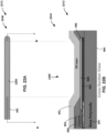
- FIG. 8B is a cross-sectional view of the distal portion 244 of FIG. 8A taken along line A-A'.
- the examples shown in FIGS. 8A-8B illustrate example relative positioning and layer structure of glucose sensor 212.
- glucose sensor 212 includes insulating body 250.
- Insulating body 250 may be a flexible, electrical insulator such as a polyimide.
- Insulating body defines first side 852 (alternatively referred to as top side 852 or front side 852) and second side 854 (alternatively referred to as bottom side 854 or back side 854).
- glucose sensor 212 includes metal adhesion layer 802 and conductive trace 804.
- Metal adhesion layer 802 is disposed on an intermediate surface 856 of insulating body 250 at a depth between first side 852 and second side 854.
- Conductive trace 804 is disposed on metal adhesion layer 802.
- Metal adhesion layer 802 is configured to promote and/or increase the adhesion of conductive trace 804 to the surface of insulating body 250.
- metal adhesion layer 802 comprises chromium, and/or titanium, or any suitable material or compound configured to increase the adhesion of conductive trace 804 to insulating body 250.
- Conductive trace 804 is configured to electrically connect electrochemical cells 254 and contact pads 262 at proximal portion 240 (not shown).
- conductive trace 804 comprises one or more of gold, silver, aluminum, copper, platinum, or any suitable conductive material.
- glucose sensor 212 includes a plurality of metal adhesion layers 802 and conductive traces 804, e.g., each of which may be offset from each other in the width direction.
- glucose sensor 212 may include individual conductive traces 804 for each electrochemical cell 254, e.g., three conductive traces 804 in the example shown.
- glucose sensor 212 includes an additional conductive trace 804 configured to connect reference electrode 258 with one or more contact pads 262 or a separate contact pad (not shown), e.g., a fourth conductive trace to carry an electrical signal from reference electrode 258.
- one or more of the electrical traces connected to electrochemical cells 254 is connected to reference electrode 258.
- intermediate surface 856 may be within a channel in insulating body 250. In other examples, intermediate surface 856 may be a surface of insulating body 250 that is subsequently covered via other layers.
- insulating top layer 850 may be subsequently disposed on the intermediate surface layer of insulating body 250, e.g., via coating, lamination, deposition, or the like, to encapsulate metal adhesion layer 802 and conductive traces 804. Insulating top layer 850 may be substantially similar to insulating body 250 and may define a portion of top side 852 corresponding to the length and width of conductive traces 804.
- insulating body 250 may be considered to include insulating top layer 850 in an arrangement configured to encapsulate conductive traces 804 within insulting body 250 at a depth between first side 852 and second side 854, e.g., to encapsulate and electrically isolate and/or insulate conductive traces 804 within polyimide.
- glucose sensor 212 includes electrocatalytic layer 806 disposed at least partially on a top surface of at least one conductive trace 804 and in electrical contact with the conductive trace 804.
- electrocatalytic layer 806 may additionally disposed on an intermediate (e.g., depth-wise between first side 852 and second side 854) surface of insulating body 250, e.g., for an increased area along its length relative to conductive trace 804, e.g., the area corresponding to the areas of electrodes 260 and 256 illustrated in FIG. 8A .
- the intermediate surface of insulating body 250 is at the same depth as the top surface of conductive traces 804, e.g., at widths adjacent to line A-A' and not visible in the cross-sectional view of FIG. 8B .
- electrocatalytic layer 806 comprises platinum. Electrocatalytic layer 806 is configured to generate an electrical signal, e.g., a current caused by a reaction with glucose catalyzed by glucose oxidase (GOx) layer 812. In the example shown, electrocatalytic layer 806 may be patterned to form electrochemical cells 254. For example, portions of insulating body 250 may be etched and/or otherwise patterned, and electrocatalytic layer 806 may be disposed (e.g., coated, vapor deposited, or the like) within the pattern to form the six electrocatalytic layers 806 areas corresponding to counter electrodes 260 and working electrodes 256 as illustrated in FIG. 8A , e.g., with insulating material, such as insulating body 250 and/or 850 separating the electrocatalytic layers 806 areas.
- an electrical signal e.g., a current caused by a reaction with glucose catalyzed by glucose oxidase (GOx) layer 812.
- glucose sensor 212 includes catalyst layer 812 disposed on a top surface of at least a portion of electrocatalytic layer 806.
- catalyst layer 812 may comprise a glucose oxidase (GOx) enzyme layer, and may be patterned.
- GOx glucose oxidase
- Catalyst layer 812 is configured to catalyze a reaction between glucose and electrocatalytic layer 806 causing an electrical signal (e.g., a current) at the electrocatalytic layer 806 proportional to the amount of glucose proximate electrochemical cells 254.
- Glucose sensor 212 may include adhesion layer 810 configured to promote, improve, and/or increase adhesion of glucose limiting layer 814 to a top surface of catalyst layer 812 and/or electrocatalytic layer 816.
- Glucose limiting layer 814 is configured to reduce an amount of glucose that reaches catalyst layer 812, e.g., to an amount of glucose within the dynamic range of catalyst 812 and/or electrocatalytic layer 806 and/or to prolong the lifetime of catalyst layer 812.
- glucose limiting layer 814 may be a glucose liming membrane.
- glucose limiting layer 814 may be configured to encapsulate electrochemical cells 254, e.g., so as to limit the glucose that may come in contact with catalyst layer 812.
- electrocatalytic layer 806, insulating body 250 and/or insulting top layer 850, and catalyst layer 812 may be patterned to form electrochemical cells 254 as illustrated in FIG. 8A .
- electrochemical cell 254A may comprise counter electrode 260A and working electrode 256A which may be positioned proximal on insulating body 250 to electrochemical cell 254B.
- Electrochemical cell 254B may comprise counter electrode 260B and working electrode 256B which may be positioned proximal on insulating body 250 to electrochemical cell 254C.
- Electrochemical cell 254C may comprise counter electrode 260C and working electrode 256C which may be positioned proximal on insulating body 250 to reference electrode 258.
- Reference electrode 258 may be at or near a distal end of glucose sensor 212.
- Reference electrode 258 may comprise conductive layer 808, which may be disposed on at least portion of one of conductive traces 804 and/or at least a portion of an intermediate surface of insulating body 250, distal to electrochemical cells 254 as shown, and/or at substantially the same depth as electrocatalytic layer 806 (e.g., so as to contact a top surface of a conductive trace).
- conductive layer 808 comprises silver, silver oxide, silver chloride and/or any other suitable conductive material.
- FIG. 9A is a top view of a distal portion 444 of example drug eluting device 412 of FIG. 5
- FIG. 9B is a cross-sectional view of the distal portion 444 of FIG. 9A taken along line B-B'.
- the examples shown in FIGS. 9A-9B illustrate example relative positioning and layer structure of drug eluting device 412.
- drug eluting device 412 includes insulating body 450.
- Insulating body 450 may be a flexible, electrical insulator such as a polyimide.
- Insulating body defines first side 952 (alternatively referred to as top side 952 or front side 952) and second side 954 (alternatively referred to as bottom side 954 or back side 954).
- Drug eluting device 412 includes metal adhesion layer 902 and conductive trace 904, which may be substantially similar to metal adhesion layer 802 and conductive trace 804 of FIG. 8B .
- Metal adhesion layer 902 is disposed on an intermediate surface 956 of insulating body 450 at a depth between first side 952 and second side 954.
- Conductive trace 904 is disposed on metal adhesion layer 902.
- Metal adhesion layer 902 is configured to promote and/or increase the adhesion of conductive trace 904 to the surface of insulating body 450.
- metal adhesion layer 902 comprises chromium, and/or titanium, or any suitable material or compound configured to increase the adhesion of conductive trace 904 to insulating body 450.
- Conductive trace 904 is configured to electrically connect background electrode 460 and contact pad 462 at proximal portion 440 (not shown).
- conductive trace 904 comprises one or more of gold, silver, aluminum, copper, platinum, or any suitable conductive material.
- intermediate surface 956 may be within a channel in insulating body 450. In other examples, intermediate surface 956 may be a surface of insulating body 450 that is subsequently covered via other layers.
- insulating top layer 950 may be subsequently disposed on the intermediate surface layer of insulating body 450, e.g., via coating, lamination, deposition, or the like, to encapsulate metal adhesion layer 902 and conductive trace 904. Insulating top layer 950 may be substantially similar to insulating body 450 and may define a portion of top side 952 corresponding to the length and width of conductive trace 904.
- insulating body 450 may be considered to include insulating top layer 950 in an arrangement configured to encapsulate conductive trace 904 within insulting body 450 at a depth between first side 952 and second side 954, e.g., to encapsulate and electrically isolate and/or insulate conductive trace 904 within polyimide.
- Conductive trace 904 may have an area corresponding to the area of background electrode 460, e.g., as illustrated in FIG. 9A .
- conductive trace 904 may be background electrode 460 for a portion of its length and/or area corresponding to background electrode 460, e.g., conductive trace 904 may be integral with background electrode 460, and conductive trace 904 may be encapsulated within insulating body 450 for a first portion of its length/area and may be exposed, e.g., not encapsulated within insulating body 450 for a second portion of its length/area defining and/or forming background electrode 460.
- Background electrode 460 e.g., the exposed area of conductive trace 904, may be configured to generate an electrical signal indicative of electrochemical interference, e.g., via an electrocatalytic reaction with an interferant such as acetaminophen.
- drug eluting device 412 includes drug eluting layer 452.
- Drug eluting layer 452 may be configured to elute a drug, such as a steroid such as dexamethasone and/or dexacetate, as described above.
- drug eluting layer 452 is configured to be exposed to fluids, e.g., blood, interstitial fluid, or the like, of the patient when at least a portion of drug eluting device 412 including drug eluting layer 452 is inserted into the patient.
- the fluids may act as a solvent extracting and/or removing the drug from drug eluting layer 452.
- drug eluting layer 452 is disposed on a top surface of background electrode 460, e.g., a top surface of the second portion of conductive trace 904. In the example shown, drug eluting layer 452 is disposed on at least a portion of the area of top side 952 of insulating body 450 and/or 850. In some examples, drug eluting layer 452 is disposed on top side 952 proximal to electrode 460, and in some examples drug eluting layer 452 is disposed on top side 952 distal to electrode 460, and in some examples, as in the example shown, drug eluting layer 452 is disposed on top side 952 proximal and distal to electrode 460.
- the surface area of background electrode 460 is greater than the surface area of one or more of electrochemical cells 254, alone or in combination.
- background electrode 460 has a greater surface area than electrodes 256, 258, 260, alone or in combination, e.g., at least by virtue of being continuous and not segmented as electrodes 260/256 are in the examples shown.
- FIG. 9C is a top view of a distal portion 474 of another example drug eluting device similar to drug eluting device 412 of FIG. 5 , the difference being that distal portion 474 includes background electrode 470 rather than background electrode 460.
- FIG. 9B is a cross-sectional view of the distal portion 474 of FIG. 9C taken along line B-B'.
- the examples shown in FIGS. 9C-9D illustrate example relative positioning and layer structure of the drug eluting device similar to drug eluting device 412.
- background electrode 470 is substantially similar to background electrode 460 except that background electrode 470 includes conductive layer 906.
- Conductive layer 906 may be the active electrode layer and/or surface of background electrode 470, and may be in electrical contact with conductive trace 904.
- Conductive layer 906 may comprise one or more of gold, silver, aluminum, copper, platinum, or any suitable conductive material.
- conductive layer 906 may have an area corresponding to the area of background electrode 470, e.g., as illustrated in FIG. 9C .
- conductive layer 906 may be background electrode 470.
- Background electrode 470 e.g., the exposed area of conductive layer 906, may be configured to generate an electrical signal indicative of electrochemical interference, e.g., via an electrocatalytic reaction with an interferant such as acetaminophen, and conductive trace 904 may be configured to receive the electrical signal indicative of electrochemical interference, via electrical contact with conductive layer 906, and conduct the electrical signal to contact pad 462.
- FIG. 10A is a top view of a distal portion 1044 of another example drug eluting device 1012
- FIG. 10B is a cross-sectional view of the distal portion 1044 of FIG. 10A taken along line B-B'.
- the examples shown in FIGS. 10A-10B illustrate example relative positioning and layer structure of drug eluting device 1012.
- Drug eluting device 1012 may be substantially similar to drug eluting device 412, except drug eluting device 1012 includes a plurality of background electrodes 1060A, 1060B, and 1060C (collectively "background electrodes 1060").
- background electrodes 1060 may be substantially similar to background electrode 460 described above, e.g., defined and/or formed via an area of conductive trace 904 being exposed and not encapsulated within insulating body 450 and/or insulating top layer 950, except that background electrodes 1060 are a plurality of individual electrode areas.
- background electrode 1060A is positioned longitudinally along the length of drug eluting device 1012 proximal to background electrode 1060B, which is positioned proximal to background electrode 1060C, which is positioned relatively near and/or proximate to the distal end of drug eluting device 1012.
- each of background electrodes 1060 correspond to the areas longitudinal positions of working electrodes 260 of glucose sensor 412, e.g., as shown in FIGS. 11A and 11B.
- FIG. 11A is a top view of example glucose sensor 212 of FIG. 8A
- FIG. 11B is a top view of the example drug eluting device 1012 of FIG. 10A and arranged for visual comparison with glucose sensor 212.
- the relative sizes and lengths of glucose sensor 412 and drug eluting device 1012 are substantially the same, as are the positions and areas of working electrodes 260 and background electrodes 1060 as highlighted by lines 1100 between FIG. 11A and FIG. 11B .
- background electrode 1060A is disposed at a first position along the length direction of insulating body 450, e.g., the length direction being along top side 952 and perpendicular the direction which top side 952, and background electrode 1060, is facing, as well as perpendicular to the opposite direction, e.g., the direction which bottom side 954 is facing.
- Working electrode 260A is disposed at the same first position along the length direction of insulating body 250, such that when assembled in the back-to-back configuration, background electrode 1060A is at the same length position as working electrode 260A and electrochemical cell 254A.
- background electrode 1060A and working electrode 260A/electrochemical cell 254A are positioned at the same depth within the patient. Additionally, background electrode 1060A has substantially the same area as working electrode 260A, e.g., so as to mimic and/or receive the same amount of electrochemical interferant, e.g., acetaminophen, as working electrode 260A and consequently generate an electrical signal due to electrochemical interference that is similar and/or the same as working electrode 260A and/or electrochemical cell 254A.
- electrochemical interferant e.g., acetaminophen
- Such an arrangement may have the benefit of easing and/or improving calibration of the electrochemical interference signal generated by background electrodes 1060 relative to the amount of iSig generated by electrochemical cells 254 due to electrochemical interference, e.g., by having background electrodes matching in area and depth position within the patient.
- Background electrodes 1060B and 1060C may be similarly matched with working electrodes 260B and 260C, respectively, and electrochemical cells 254B and 254C, respectively.
- FIG. 12A is a top view of a distal portion 1244 of another example drug eluting device 1212
- FIG. 12B is a cross-sectional view of the distal portion 1244 of FIG. 12A taken along line B-B'.
- the examples shown in FIGS. 12A-12B illustrate example relative positioning and layer structure of drug eluting device 1212.
- Drug eluting device 1212 may be substantially similar to drug eluting device 412, except drug eluting device 1212 includes adhesion layer 810 disposed on background electrode 1260 (e.g., disposed on the top surface of conductive trace 904) and glucose limiting layer 814 disposed on adhesion layer 810.
- background electrode 1260 may be substantially similar to background electrode 460 described above, e.g., defined and/or formed via an area of conductive trace 904 being exposed and not encapsulated within insulating body 450 and/or insulating top layer 950, except that background electrode 1260 further includes adhesion layer 810 and glucose limiting layer 814, e.g., as described above at FIGS. 8A and 8B .
- background electrode 1260 comprises glucose limiting layer 814 (e.g., a glucose limiting membrane) disposed over the top surface of background electrode 1260 (e.g., the top surface of conductive trace 904).
- Background electrode 1260 may provide the benefit of better mimicking the signal of electrochemical cells 254 caused by an electrochemical interferant, e.g., by including components of the layer structure of electrochemical cells 254, e.g., adhesion layer 810 and glucose limiting layer 814. Such components may change the amount and/or rate of electrochemical interferent reaching an electrocatalytic layer and/or conductive layer to cause an electrochemical interference signal.
- FIG. 13A is a top view of a distal portion 1344 of another example drug eluting device 1312
- FIG. 13B is a cross-sectional view of the distal portion 1344 of FIG. 13A taken along line B-B'.
- the examples shown in FIGS. 13A-13B illustrate example relative positioning and layer structure of drug eluting device 1312.
- Drug eluting device 1312 may be substantially similar to drug eluting device 1212, except drug eluting device 1312 does not include adhesion layer 810 or glucose limiting layer 814.
- background electrode 1360 may be substantially similar to background electrode 460 described above, e.g., defined and/or formed via an area of conductive trace 904 being exposed and not encapsulated within insulating body 450 and/or insulating top layer 950.
- drug eluting layer 452 is disposed on and/or over first side 952 of insulating top layer 950 proximal to background electrode 1360.
- top layer 950 may have a surface depth profile, e.g., a surface relief pattern in which the depth of the top surface of first side 952 varies over its area.
- drug eluting layer 452 may be disposed on or over such a surface relief pattern and may have a top surface that is substantially the same as the surface relief pattern of first side 952, or drug eluting layer 452 may have a top surface that planarizes the surface relief pattern, e.g., as shown in FIG. 13B .
- FIG. 14A is a top view of a distal portion 1444 of another example drug eluting device 1412
- FIG. 14B is a cross-sectional view of the distal portion 1444 of FIG. 14A taken along line B-B'.
- the examples shown in FIGS. 14A-14B illustrate example relative positioning and layer structure of drug eluting device 1412.
- background electrode 1460 may be substantially similar to background electrode 460 described above.
- Drug eluting device 1412 may be substantially similar to drug eluting device 1312, except that drug eluting layer 452 is disposed on and/or over first side 952 of insulating top layer 950 distal to background electrode 1460.
- FIG. 15A is a top view of a distal portion 1544 of another example drug eluting device 1512
- FIG. 15B is a cross-sectional view of the distal portion 1544 of FIG. 15A taken along line B-B'.
- the examples shown in FIGS. 15A-15B illustrate example relative positioning and layer structure of drug eluting device 1512.
- background electrode 1560 may be substantially similar to background electrode 460 described above.
- Drug eluting device 1512 may be substantially similar to drug eluting devices 1212 and/ or 1312, except that drug eluting layer 452 is disposed on and/or over first side 952 of insulating top layer 950 distal to background electrode 1460.
- FIG. 16A is a top view of a distal portion 1644 of another example drug eluting device 1612
- FIG. 16B is a bottom view of the distal portion 1644 of example drug eluting device 1612
- FIG. 16C is a cross-sectional view of the distal portion 1644 of FIGS. 16A and 16B taken along line B-B'.
- the examples shown in FIGS. 16A-16C illustrate example relative positioning and layer structure of drug eluting device 1612.
- Drug eluting device 1612 may be substantially similar to drug eluting device 412 of FIGS. 9A and 9B , except that background electrode 1660 is disposed on the second side 954 (e.g., bottom or back side 952) of insulating body 450 and not the first side 952 (e.g., top or front side 952).
- metal adhesion layer 902 is disposed on second surface 954 of insulating body 450, and conductive trace 904 is disposed on metal adhesion layer 902.
- background electrode 1660 e.g., at least a portion of conductive trace 904, may have an area similar to any of the example background electrodes disclosed herein, except background electrode 1660 is disposed on second side 954.
- the area of background electrode 1660 is substantially all of the area of second side 954 of distal portion 1644.
- drug eluting layer 452 is disposed on first side 952, which in the example shown in the first side (e.g., top and/or front side) of insulating body 450.
- drug eluting layer 452 may have an area similar to any of the example drug eluting layers disclosed herein. In the example shown, the area of drug eluting layer 452 is substantially all of the area of first side 952 of distal portion 1644.
- FIG. 17A is a top view of a distal portion 1744 of another example drug eluting device 1712
- FIG. 17B is a bottom view of the distal portion 1744 of example drug eluting device 1712
- FIG. 17C is a cross-sectional view of the distal portion 1744 of FIGS. 17A and 17B taken along line B-B'.
- the examples shown in FIGS. 17A-17C illustrate example relative positioning and layer structure of drug eluting device 1712.
- Drug eluting device 1712 may be substantially similar to drug eluting device 1612, except that drug eluting device 1712 includes insulting bottom layer 1750 is disposed on and/or over at least a portion of conductive trace 904 on the second side 954.
- Insulating bottom layer 1750 may be substantially the same as insulating top layer 950, except that insulating bottom layer 1750 is disposed on and/or over at least a portion of a surface of conductive trace 904 and/or background electrode 1760 on the second side 954.
- second side 954 may be a surface of insulating body 450, and insulting bottom layer 1750 may define second side 1754 which may define an outer surface 1754 of drug eluting device 1712 facing the second direction, e.g., opposite the first direction in which first side 952 faces.
- background electrodes 1660 and 1760 may be "backside” electrodes, and background electrode 1760 may be a “segmented" backside electrode, e.g., having an area that is less than the second side 1754 area of distal portion 1744 and corresponding to an area of conductive trace 904 that is exposed and/or uncovered by insulating bottom layer 950.
- FIG. 18A is a top view of a distal portion 1844 of another example drug eluting device 1812
- FIG. 18B is a bottom view of the distal portion 1844 of example drug eluting device 1812
- FIG. 18C is a cross-sectional view of the distal portion 1844 of FIGS. 18A and 18B taken along line B-B'.
- the examples shown in FIGS. 18A-18C illustrate example relative positioning and layer structure of drug eluting device 1812.
- drug eluting device 1812 includes background electrode 1860 which may be substantially similar to background electrode 1760 of FIGS. 17A-17C .
- Drug eluting device 1812 may be substantially similar to drug eluting device 1712, except that drug eluting layer 452 is disposed on second side 1754.
- drug eluting layer 452 may be disposed on at least a portion of second side 1754, e.g., an outer surface of bottom insulting layer 1750, at least a portion of a surface of background electrode 1860, or both.
- drug eluting layer 542 is disposed on both first side 952 and second side 1754.
- FIG. 19A is a top view of a distal portion 1944 of another example drug eluting device 1912
- FIG. 19B is a bottom view of the distal portion 1944 of example drug eluting device 1912
- FIG. 19C is a cross-sectional view of the distal portion 1944 of FIGS. 19A and 19B taken along line B-B'.
- the examples shown in FIGS. 19A-19C illustrate example relative positioning and layer structure of drug eluting device 1912.
- drug eluting device 1912 includes background electrode 1960 which may be substantially similar to background electrode 1360 of FIGS. 13A -13C
- drug eluting device 1912 includes background electrode 1970 which may be substantially similar to background electrode 1660 of FIGS. 16A-16C .
- drug eluting device 1912 may be substantially similar to a combination of drug eluting devices 1312 and 1612, e.g., including a first side 932 background electrode 1960 and a second side 954 background electrode 1970.
- background electrode 1970 comprises conductive trace 1904, which is disposed on metal adhesion layer 1902, which is disposed on second side 954 of insulating body 450.
- Conductive trace 1904 and metal adhesion layer 1902 may be substantially similar to conductive trace 904 and metal adhesion layer 902.
- background electrodes 1960 and 1970 may be combined to form a single background electrode, e.g., by way of being electrically connected by via 1906 as in the example shown.
- Via 1906 may comprise any suitable conductor, e.g., platinum, gold, silver, aluminum, copper, or the like.
- background electrode 1960 may be further disposed on second side 954 of insulating body 450.
- background electrodes 1960 and 1970 may be separate background electrodes, e.g., drug eluting device 1912 may not include via 1906.
- conductive traces 904 and 1904 may electrically connect background electrodes 1960 and 1970 to different contact pads (not shown) at a proximal portion of drug eluting device 1912, each of which may be substantially similar to contact pad 462 of FIG. 5 .
- background electrode 1960 may be a first background electrode disposed on first side 952 of insulating body 450
- background electrode 1970 may be a second background electrode disposed on second side 954 of insulating body 450.
- drug eluting device 1912 includes drug eluting layer 452.
- drug eluting layer 452 is disposed at least partially on first side 952 and/or at least partially on a surface of background electrode 1960.
- FIG. 20A is a top view of a distal portion 2044 of another example drug eluting device 2012
- FIG. 20B is a bottom view of the distal portion 2044 of example drug eluting device 2012
- FIG. 20C is a cross-sectional view of the distal portion 2044 of FIGS. 20A and 20B taken along line B-B'.
- the examples shown in FIGS. 20A-20C illustrate example relative positioning and layer structure of drug eluting device 2012.
- drug eluting device 2012 includes background electrode 2060 which may be substantially similar to background electrode 1960 of FIGS. 19A-19C
- drug eluting device 2012 includes background electrode 2070 which may be substantially similar to background electrode 1970 of FIGS. 19A-19C .
- Drug eluting device 2012 may be substantially similar to drug eluting device 1912, except that drug eluting device 2012 includes insulting bottom layer 1750 disposed on and/or over at least a portion of conductive trace 1904 on the second side 954.
- Insulating bottom layer 1750 may be substantially the same as insulating top layer 950, except that insulating bottom layer 1750 is disposed on and/or over at least a portion of a surface of conductive trace 1904 and/or background electrode 2060 on the second side 954.
- second side 954 may be a surface of insulating body 450, and insulting bottom layer 1750 may define second side 1754 which may define an outer surface 1754 of drug eluting device 2012 facing the second direction, e.g., opposite the first direction in which first side 952 faces.
- FIG. 21A is a top view of a distal portion 2144 of another example drug eluting device 2112
- FIG. 21B is a cross-sectional view of the distal portion 2144 of FIG. 21A taken along line B-B'.
- the examples shown in FIGS. 21A-21B illustrate example relative positioning and layer structure of drug eluting device 2112.
- Drug eluting device 2112 may be substantially similar to drug eluting device 912, except that background electrode 2160 has a thicker conductive area than background electrode 906.
- drug eluting device 2112 includes conductive trace 2104 which may be substantially similar to conductive trace 904 except that the thickness and/or depth of conductive trace 2104 for a portion of its area corresponding to an active area and/or exposed area of background electrode 2160 at distal portion 2144 is increased, and in some examples an outer surface of conductive trace 2104 (e.g., and background electrode 2160) may be substantially coplanar with insulating top layer 950, e.g., coplanar with the outer surface of first side 954.
- insulating top layer 950 is disposed over a first portion of a surface of background electrode 2160, e.g., the thinner portion of conductive trace 2104 in the example shown.
- drug eluting layer 452 is disposed over at least a portion of insulating top layer 950 and at least a portion of the area of background electrode 2160, e.g., at least a portion of the thicker area of conductive trace 2104.
- drug eluting layer 452 is disposed over insulating top layer 950 at a first portion of distal portion 2144 and drug eluting layer 452 is disposed over a second portion of distal portion 2144 corresponding to at least a portion of the surface of background electrode 2160 and the thickness of drug eluting layer 452 is substantially the same at the first and second portions.
- drug eluting layer 452 has a substantially constant thickness and an outer surface at a substantially constant depth/thickness plane over at least portions of both insulating top layer 950 and the outer surface area of background electrode 2160.
- FIG. 22A is a top view of a distal portion 2244 of another example drug eluting device 2212
- FIG. 22B is a cross-sectional view of the distal portion 2244 of FIG. 22A taken along line B-B'.
- the examples shown in FIGS. 22A-22B illustrate example relative positioning and layer structure of drug eluting device 2212.
- Drug eluting device 2212 may be substantially similar to drug eluting device 912, except that insulating top layer 950 tapers in thickness between a first thickness and a zero thickness, e.g., at a perimeter of the active and/or exposed surface area of background electrode 2260 as in the example shown.
- background electrode 2260 is substantially similar to background electrode 2160 except that conductive trace 904 does not have a substantial increase in thickness at the active and/or exposed area of background electrode 2260, and insulating top layer 950 tapers down in thickness to a plane including the outer surface of conductive trace 904.
- drug eluting layer 452 is disposed over first side 952 and over at least a portion of both top insulating layer 950 and at least a portion of the surface area of background electrode 2260 similar to drug eluting device 2112, except that drug eluting layer 452 follows the surface profile of the taper of insulating top layer 950.
- drug eluting layer 452 is disposed over insulating top layer 950 at a first portion of distal portion 2244 and drug eluting layer 452 is disposed over a second portion of distal portion 2244 corresponding to at least a portion of the surface of background electrode 2260 and the thickness of drug eluting layer 452 is substantially the same at the first and second portions.
- drug eluting layer 452 has a substantially constant thickness and an outer surface that changes depth/thickness plane when over a portion of insulating top layer 950 versus over the outer surface area of background electrode 2160, e.g., as illustrated in FIG. 22B .
- FIG. 23 is a top view of another example glucose sensor 2312.
- Glucose sensor 2312 may be substantially similar to glucose sensor 212 of FIGS. 4 , 8A, and 8B , except that glucose sensor 2312 includes background electrode 2360 and contact pad 2362.
- Background electrode 2360 may be substantially similar to any of background electrode 460, except with conductive trace 804 as the conductive surface of background electrode 460, or counter electrodes 260, reference electrodes 258, or working electrodes 256 except without adhesion layer 810 and/or GOx layer 812.
- background electrode 2360 is disposed on first side 852 of insulating body 850 and proximal to any or all of electrochemical cells 254.
- the surface area, e.g., the active and/or exposed surface area of background electrode 2360 comprises an area that is from 20% to 50% a surface area of any one of electrochemical cell 254 or all of electrochemical cells 254 in combination.
- the longitudinal length of distal portion 2344 of glucose sensor 2312 is extended and/or lengthened, e.g., relative to distal portion 244 of glucose sensor 212.
- distal portion 2344 is relatively longer than distal portion 244 via the inclusion of background electrode 2360.
- length L of distal portion 2360 corresponds to length L of distal portion 244 illustrated in FIGS. 8A and 8B .
- glucose sensor 2312 may be used with drug eluting device 2812 of FIGS. 28A and 28B illustrated and described below, e.g., in medical device 200 and/or in a back-to-back configuration as described above.
- FIG. 24 is a top view of another example glucose sensor 2412.
- Glucose sensor 2412 may be substantially similar to glucose sensor 2312 of FIG. 23 , except that background electrode 2460 is included in the longitudinal length L, e.g., that corresponds to the longitudinal length L of glucose sensor 212, and counter electrodes 2456 are reduced to accommodate for the area of background electrode 2460.
- glucose sensor 2412 may be substantially same length as glucose sensor 212 and include a background electrode 2460 substantially similar to background electrode 2360 of glucose sensor 2312, with counter electrodes 2456 being reduced relative to counter electrodes 256 to accommodate for the length of background electrode 2460.
- Electrochemical cells 2454 may be substantially similar to electrochemical cells 254, except having the reduced length counter electrodes 2461 rather than counter electrodes 260.
- the surface area, e.g., the active and/or exposed surface area of background electrode 2460 comprises an area that is from 20% to 50% a surface area of any one of electrochemical cells 2454 or all of electrochemical cells 2454 in combination.
- glucose sensor 2412 may be used with drug eluting device 2812 of FIGS. 28A and 28B illustrated and described below, e.g., in medical device 200 and/or in a back-to-back configuration as described above.
- FIG. 25 is a top view of another example glucose sensor 2512.
- Glucose sensor 2512 may be substantially similar to glucose sensor 2312 of FIG. 23 , except that glucose sensor 2512 includes background electrode 2560 positioned between counter electrode 256A and working electrode 260A rather than background electrode 2360.
- Background electrode 2560 may be substantially similar to background electrode 2360, except background electrode 2560 is positioned between counter electrode 256A and working electrode 260A.
- FIG. 26A is a top view of a distal portion 2644 of another example glucose sensor 2612
- FIG. 26B is a bottom view of the distal portion 2644 of example glucose sensor 2612
- FIG. 26C is a cross-sectional view of the distal portion 2644 of FIGS. 26A and 26B taken along line A-A'.
- Glucose sensor 2612 may be substantially similar to glucose sensor 212 of FIGS. 4 , 8A, and 8B , except that glucose sensor 2612 includes background electrode 2660 disposed on second side 854.
- glucose sensor 2612 includes electrochemical cells 254 disposed on a first side 852 of insulating body 250 and/or insulating top layer 850 and background electrode 2660 disposed on second side 854 of insulating body 250 opposite first side 852.
- glucose sensor 2660 includes metal adhesion layer 2602 and conductive trace 2604 disposed on second side 854 of insulating body 250.
- metal adhesion layer 2602 and conductive trace 2604 are substantially similar to metal adhesion layer 802 and conductive trace 804.
- glucose sensor 2660 includes a fourth contact pad (not shown) electrically connected to background electrode 2660 by conductive trace 2604.
- Background electrode 2660 may be substantially similar to background electrode 2070 of FIG. 20C , only disposed on the second side 854 of insulating body 250 of glucose sensor 212 rather than a separate drug eluting device.
- glucose sensor 2612 may be used with drug eluting device 2812 of FIGS. 28A and 28B illustrated and described below, e.g., in medical device 200 and/or in a back-to-back configuration as described above.
- FIG. 27A is a top view of a distal portion 2744 of another example glucose sensor 2712
- FIG. 27B is a bottom view of the distal portion 2744 of example glucose sensor 2712
- FIG. 27C is a cross-sectional view of the distal portion 2744 of FIGS. 27A and 27B taken along line A-A'.
- Glucose sensor 2712 may be substantially similar to glucose sensor 2612 of FIGS. 26A-26C , except that background electrode 2760 includes glucose limiting layer 814 disposed on and/or over at least a portion of the surface of background electrode 2760.
- background electrode 2760 is substantially similar to background electrode 2660, except background electrode 2760 includes glucose limiting layer 814 dispose on at least a portion of its outer surface.
- FIG. 28A is a top view of a distal portion 2844 of another example drug eluting device 2812
- FIG. 28B is a cross-sectional view of the distal portion 2844 of FIG. 28A taken along line B-B'.
- the examples shown in FIGS. 28A -28B illustrate example relative positioning and layer structure of drug eluting device 2812.
- Drug eluting device 2812 may be substantially similar to drug eluting device 412, except drug eluting device 2812does not include a background electrode.
- FIG. 29 is a flowchart illustrating an example method of determining a glucose level of a fluid of a person.
- the example technique of FIG. 29 may be performed with any type of monitoring device and/or glucose sensor, e.g., including processing circuitry such as measurement processor 132 and/or controller 136, and/or any glucose sensor and/or drug eluting device disclosed here.
- the example technique of FIG. 29 may be performed by processing circuitry (e.g., measurement processor 132), configured to execute instructions stored in memory (e.g., memory 140), such as interference detection unit 142.
- Measurement processor 132 may receive a first signal indicative of an amount of glucose in a fluid of a person from an electrochemical cell (2902). For example, measurement processor 132 receive iSig from one or more of electrochemical cells 254. Measurement processor 132 may receive a second signal indicative of an amount of electrochemical interference in a fluid of a person from a background electrode (2904). For example, measurement processor 132 receive a current signal other than iSig from background electrode 460. In some examples, background electrode 460 is configured to not catalyze a reaction with glucose, and is positioned proximate and/or relatively close to one or more of electrochemical cells 254.
- electrochemical cells 254 may be disposed on a first side of glucose sensor 212 that is separate from drug eluting device 412, and background electrode 460 is disposed on a first side of drug eluting device 412.
- glucose sensor 212 and drug eluting device 412 are arranged in a back-to-back configuration, e.g., as described above.
- Measurement processor 132 may determine a glucose level of the fluid of the person based on the first and second signals (2906). For example, measurement process 132 may subtract the second signal from the first signal to determine a glucose level of the fluid of the person. In some examples, measurement processor 132 may adjust and/or "weight" each of the first and second signals with the same or different adjustments and/or weights, e.g., via a calibration configured to adjust for differences in electrochemical cells 254 generating a signal due to electrochemical interference (e.g., in addition to the signal generated due to glucose) and background electrode 440 generating the second signal due to electrochemical interference.
- electrochemical interference e.g., in addition to the signal generated due to glucose
- a device includes: an electrochemical cell configured to generate a first electrical signal indicative of an amount of glucose in a fluid of a person, the electrochemical cell comprising a working electrode, a counter electrode, and a reference electrode; and a background electrode configured to not catalyze a reaction with glucose and is configured to generate a second electrical signal indicative of an amount of electrochemical interference proximate the electrochemical cell.
- Example 2 The device of example 1, wherein the electrochemical cell is disposed on a first side of a first body, wherein the background electrode is disposed on a first side of a second body separate from the first body.
- Example 3 The device of example 2, wherein the first side of the first body faces a first direction, wherein the first side of the second body faces a second direction opposite the first direction, wherein a second side of the first body opposite the first side of the first body is adjacent a second side of the second body, the second side of the second body opposite the first side of the second body.
- Example 4 The device of example 3, wherein a drug eluting layer is disposed on the first side of the second body.
- Example 5 The device of example 4, wherein the drug eluting layer is disposed on the first side of the second body proximal to the background electrode.
- Example 6 The device of example 4, wherein the drug eluting layer is disposed on the first side of the second body distal to the background electrode.
- Example 7 The device of example 4, wherein the drug eluting layer is disposed on the first side of the second body proximal and distal to the background electrode.
- Example 8 The device of any one of examples 3 through 7, wherein a surface area of the background electrode is greater than a surface area of the electrochemical cell.
- Example 9 The device of any one of examples 3 through 8, wherein the background electrode is disposed at a first position along a length direction of the second body, the length direction perpendicular to the first and second directions, wherein the electrochemical cell is disposed at the first position along the first body.
- Example 10 The device of any one of examples 4 through 9, wherein the drug eluting layer is disposed on at least a portion of the surface of the background electrode.
- Example 11 The device of any one of examples 3 through 10, wherein the background electrode comprises a glucose limiting membrane disposed over the background electrode surface.
- Example 12 The device of any one of examples 3 through 11, wherein the background electrode is disposed on the second side of the second body and not the first side of the second body.
- Example 13 The device of any of examples 11 and 12 or any of examples 11 and 12, wherein an insulator is disposed over at least a portion of a surface of the background electrode.
- Example 14 The device of any one of examples 4 through 13, wherein the background electrode is further disposed on a second side of the second body.
- Example 15 The device of example 14, wherein an insulator is disposed over a portion of a surface of the background electrode on the second side of the second body.
- Example 16 The device of any one of examples 4 through 15, wherein an insulator is disposed over a first portion of a surface of the background electrode, wherein a second portion of the surface of the background electrode is coplanar with the insulator.
- Example 17 The device of any one of examples 4 through 16, wherein an insulator is disposed over a first portion of a surface of the background electrode, wherein the drug eluting layer is disposed over the insulator at the first portion and over a second portion of the surface of the background electrode, wherein the thickness of the drug eluting layer is the same at the first and second portions.
- Example 18 The device of any one of examples 1 through 17, wherein the background electrode is proximal the electrochemical cell.
- Example 19 The device of example 18, wherein a surface area of the background electrode comprises an area that is from 20% to 50% a surface area of the electrochemical cell.
- Example 20 The device of any one of examples 1 through 19, wherein the background electrode is positioned between the counter electrode and the working electrode.
- Example 21 The device of any one of examples 1 through 20, wherein the electrochemical cell is disposed on a first side of a first body, wherein the background electrode is disposed on a second side of the first body opposite the first side.
- Example 22 The device of example 21, wherein the electrochemical cell comprises a glucose limiting membrane, wherein the background electrode comprises the glucose limiting membrane.
- Example 23 The device of any one of examples 1 through 22, wherein the electrochemical interference is caused by acetaminophen.
- Example 24 The device of any one of examples 1 through 23, wherein the surface of the electrode comprises an electrocatalytic material.
- Example 25 The device of example 24, wherein the electrocatalytic material is at least one of gold or platinum.
- Example 26 The device of any one of examples 4 through 25, wherein the drug eluting layer comprises at least one of dexamethasone or dexacetate.
- a glucose monitor system includes: an electrochemical cell configured to generate a first electrical signal indicative of an amount of glucose in a fluid of a person, the electrochemical cell disposed on a first side of a first insulative substrate; a background electrode configured to not catalyze a reaction with glucose and is configured to generate a second electrical signal indicative of an amount of electrochemical interference, the background electrode disposed on a first side of a second insulative substrate, wherein a second side opposite the first side of the first insulative substrate is adjacent to a second side opposite the first side of the second insulative substrate; and an electrical circuit configured to receive the first electrical signal indicative of the amount of glucose and the second electrical signal indicative of the amount of electrochemical interference, wherein the electrical circuit is configured to determine an amount of glucose based on the first signal and the second signal.
- Example 28 The glucose monitor system of example 27, wherein the electrical circuit is connected to the electrochemical cell via a first electrical contact in contact with the first surface of the first insulative substrate, wherein the electrical circuit is connected to the electrode via a second electrical contact in contact with a connector configured to contact the first surface of the second insulative substrate and the second electrical contact.
- Example 29 The glucose monitor system of any of examples 27 and 28 or any of examples 27 and 28, wherein a drug eluting layer is disposed on at least one of a surface of the background electrode, the first side of the second body proximal to the background electrode, the first side of the second body distal to the background electrode, or the first side of the second body proximal and distal to the background electrode.
- Example 30 The glucose monitor system of any one of examples 27 through 29, wherein a surface area of the background electrode is greater than a surface area of the electrochemical cell.
- Example 31 The glucose monitor system of any one of examples 27 through 30, wherein the background electrode is disposed at a first position along a length direction of the second body, the length direction perpendicular to the first and second directions, wherein the electrochemical cell is disposed at the first position along the first body.
- Example 32 The glucose monitor system of any one of examples 27 through 31, wherein the background electrode comprises a glucose limiting membrane disposed over the background electrode surface.
- Example 33 The glucose monitor system of any one of examples 27 through 32, wherein a drug eluting layer is disposed on a second side of the second body opposite the first side.
- Example 34 The glucose monitor system of example 33, wherein an insulator is disposed over a portion of a surface of the background electrode.
- Example 35 The glucose monitor system of any of examples 33 and 34, wherein the drug eluting layer is disposed on the first side of the second body and over a surface of the background electrode.
- Example 36 The glucose monitor system of any one of examples 27 through 35, wherein the background electrode is further disposed on a second side of the second body.
- Example 37 The glucose monitor system of example 36, wherein an insulator is disposed over a portion of a surface of the background electrode on the second side of the second body.
- Example 38 The glucose monitor system of any one of examples 27 through 37, wherein an insulator is disposed over a first portion of a surface of the background electrode, wherein a second portion of the surface of the background electrode is coplanar with the insulator.
- Example 39 The glucose monitor system of any one of examples 27 through 38, wherein an insulator is disposed over a first portion of a surface of the background electrode, wherein the drug eluting layer is disposed over the insulator at the first portion and over a second portion of the surface of the background electrode, wherein the thickness of the drug eluting layer is the same at the first and second portions.
- Example 40 The glucose monitor system of any one of examples 27 through 39, wherein the background electrode is proximal the electrochemical cell.
- Example 41 The glucose monitor system of example 40, wherein a surface area of the background electrode comprises an area that is from 20% to 50% a surface area of the electrochemical cell.
- Example 42 The glucose monitor system of any one of examples 27 through 41, wherein the background electrode is between the counter electrode and the working electrode.
- Example 43 The glucose monitor system monitor system of any one of examples 27 through 42, wherein the electrochemical cell is disposed on a first side of a body, wherein the background electrode is disposed on a second side of the body opposite the first side.
- Example 44 The glucose monitor system of example 43, wherein the electrochemical cell comprises a glucose limiting membrane, wherein the background electrode comprises the glucose limiting membrane.
- Example 45 The glucose monitor system of any one of examples 27 through 44, wherein the electrochemical interference is caused by acetaminophen.
- Example 46 The glucose monitor system of any one of examples 27 through 45, wherein the surface of the electrode comprises an electrocatalytic material.
- Example 47 The glucose monitor system of example 46, wherein the electrocatalytic material is at least one of gold or platinum.
- Example 48 The glucose monitor system of any one of examples 27 through 47, wherein the drug eluting layer comprises at least one of dexamethasone or dexacetate.
- Example 49 A method includes: receiving, from an electrochemical cell, a first signal indicative of an amount of glucose in a fluid of a person; receiving, from a background electrode configured to not catalyze a reaction with glucose and positioned proximate the electrochemical cell, a second signal indicative of an amount of electrochemical interference; and determining a glucose level of the fluid of the person based on the first and second signals.
- Example 50 The method of any of examples 24 through 49, wherein the electrochemical cell is disposed on a first side of a first body, wherein the background electrode is disposed on a first side of a second body.
- processors including one or more microprocessors, digital signal processors (DSPs), application specific integrated circuits (ASICs), field programmable gate arrays (FPGAs), or any other equivalent integrated or discrete logic circuitry, as well as any combinations of such components.
- DSPs digital signal processors
- ASICs application specific integrated circuits
- FPGAs field programmable gate arrays
- processors may generally refer to any of the foregoing logic circuitry, alone or in combination with other logic circuitry, or any other equivalent circuitry.
- a control unit comprising hardware may also perform one or more of the techniques of this disclosure.
- Such hardware, software, and firmware may be implemented within the same device or within separate devices to support the various operations and functions described in this disclosure.
- any of the described units, modules or components may be implemented together or separately as discrete but interoperable logic devices. Depiction of different features as modules or units is intended to highlight different functional aspects and does not necessarily imply that such modules or units must be realized by separate hardware or software components. Rather, functionality associated with one or more modules or units may be performed by separate hardware or software components, or integrated within common or separate hardware or software components.
- Computer-readable medium such as a computer-readable storage medium, containing instructions. Instructions embedded or encoded in a computer-readable medium may cause a programmable processor, or other processor, to perform the method, e.g., when the instructions are executed.
- Computer-readable media may include non-transitory computer-readable storage media and transient communication media.
- Computer readable storage media which is tangible and non-transitory, may include random access memory (RAM), read only memory (ROM), programmable read only memory (PROM), erasable programmable read only memory (EPROM), electronically erasable programmable read only memory (EEPROM), flash memory, a hard disk, a CD-ROM, a floppy disk, a cassette, magnetic media, optical media, or other computer-readable storage media.
- RAM random access memory
- ROM read only memory
- PROM programmable read only memory
- EPROM erasable programmable read only memory
- EEPROM electronically erasable programmable read only memory
- flash memory a hard disk, a CD-ROM, a floppy disk, a cassette, magnetic media, optical media, or other computer-readable storage media.
Landscapes
- Health & Medical Sciences (AREA)
- Life Sciences & Earth Sciences (AREA)
- Physics & Mathematics (AREA)
- Biomedical Technology (AREA)
- Medical Informatics (AREA)
- Biophysics (AREA)
- Pathology (AREA)
- Engineering & Computer Science (AREA)
- Veterinary Medicine (AREA)
- Heart & Thoracic Surgery (AREA)
- Optics & Photonics (AREA)
- Molecular Biology (AREA)
- Surgery (AREA)
- Animal Behavior & Ethology (AREA)
- General Health & Medical Sciences (AREA)
- Public Health (AREA)
- Emergency Medicine (AREA)
- Measurement Of The Respiration, Hearing Ability, Form, And Blood Characteristics Of Living Organisms (AREA)
Abstract
An example device includes an electrochemical cell configured to generate a first electrical signal indicative of an amount of glucose in a fluid of a person, the electrochemical cell comprising a working electrode, a counter electrode, and a reference electrode; and a background electrode configured to not catalyze a reaction with glucose and is configured to generate a second electrical signal indicative of an amount of electrochemical interference proximate the electrochemical cell.
Description
- This application claims the benefit of
U.S. Provisional Application No. 63/365,451, filed May 27, 2022 - This disclosure relates to glucose sensors.
- Glucose sensors are configured to detect and/or quantify the amount of glucose in a patient's body (e.g., interstitial glucose or possibly blood glucose), which enables patients and medical personnel to monitor physiological conditions within the patient's body. In some examples, it may be beneficial to monitor glucose levels on a continuing basis (e.g., in a diabetic patient). Thus, glucose sensors have been developed for use in obtaining an indication of glucose levels in a diabetic patient. Such indications are useful in monitoring and/or adjusting a treatment regimen, which typically includes administration of insulin to the patient.
- A patient can measure their blood glucose (BG) using a BG measurement device (i.e., glucose meter), such as a test strip meter. A continuous glucose measurement system (or a continuous glucose monitor (CGM)) may be configured to determine interstitial glucose; although possible for CGM to determine blood glucose. A hospital hemocue may also be used to determine glucose level. CGMs may be beneficial for patients who desire to take more frequent glucose measurements. Some example CGM systems include subcutaneous (or short-term) sensors and implantable (or long-term) sensors. A CGM system may execute an initialization sequence when the CGM is inserted into a patient. The initialization sequence may speed up sensor equilibration and may allow a CGM system to provide reliable glucose measurements earlier.
- In general, this disclosure describes systems and techniques for determining electrochemical interference of glucose sensors (e.g., a continuous glucose monitor or "CGM") based on background signal detection. More particularly, this disclosure describes systems and devices including one or more background electrodes configured to generate a signal corresponding to electrochemical interference. The electrochemical interference may interfere with accurately determining the glucose level. By determining the signal corresponding to the electrochemical interference, a device (e.g., glucose sensor or possibly some other device) may more accurately determine the glucose level.
- In one example, this disclosure describes a device including an electrochemical cell configured to generate a first electrical signal indicative of an amount of glucose in a fluid of a person, the electrochemical cell comprising a working electrode, a counter electrode, and a reference electrode; and a background electrode configured to not catalyze a reaction with glucose and is configured to generate a second electrical signal indicative of an amount of electrochemical interference proximate the electrochemical cell.
- In another example, this disclosure describes a glucose monitor system including an electrochemical cell configured to generate a first electrical signal indicative of an amount of glucose in a fluid of a person, the electrochemical cell disposed on a first side of a first insulative substrate; a background electrode configured to not catalyze a reaction with glucose and is configured to generate a second electrical signal indicative of an amount of electrochemical interference, the background electrode disposed on a first side of a second insulative substrate, wherein a second side opposite the first side of the first insulative substrate is adjacent to a second side opposite the first side of the second insulative substrate; and an electrical circuit configured to receive the first electrical signal indicative of the amount of glucose and the second electrical signal indicative of the amount of electrochemical interference, wherein the electrical circuit is configured to determine an amount of glucose based on the first signal and the second signal..
- In another example, this disclosure describes a method including receiving, from an electrochemical cell, a first signal indicative of an amount of glucose in a fluid of a person; receiving, from a background electrode configured to not catalyze a reaction with glucose and positioned proximate the electrochemical cell, a second signal indicative of an amount of electrochemical interference; and determining a glucose level of the fluid of the person based on the first and second signals.
- Further disclosed herein is an example device which includes an electrochemical cell configured to generate a first electrical signal indicative of an amount of glucose in a fluid of a person, the electrochemical cell comprising a working electrode, a counter electrode, and a reference electrode; and a background electrode configured to not catalyze a reaction with glucose and is configured to generate a second electrical signal indicative of an amount of electrochemical interference proximate the electrochemical cell.
- The details of one or more examples are set forth in the accompanying drawings and the description below. Other features, objects, and advantages will be apparent from the description and drawings, and from the claims.
-
-
FIG. 1 is a block diagram illustrating an example glucose sensor, in accordance with one or more examples described in this disclosure. -
FIG. 2 is a block diagram illustrating example sensor electrodes and a voltage being applied to the sensor electrodes. -
FIG. 3 is a cross-sectional view of an example medical device including a glucose sensor. -
FIG. 4 is a top view of an example glucose sensor. -
FIG. 5 is a top view of an example drug eluting device. -
FIG. 6 is an exploded view of the example medical device including the glucose sensor ofFIG. 3 and the example background sensor ofFIG. 5 . -
FIG. 7 is a perspective view of an example circuit board of a medical device for using with a glucose sensor. -
FIG. 8A is a top view of a distal portion of an example glucose sensor. -
FIG. 8B is a cross-sectional view of the distal portion of the example glucose sensor ofFIG. 8A . -
FIG. 9A is a top view of a distal portion of an example drug eluting device including a background electrode. -
FIG. 9B is a cross-sectional view of the distal portion of the example drug eluting device ofFIG. 9A . -
FIG. 9C is a top view of a distal portion of another example drug eluting device including a background electrode. -
FIG. 9D is a cross-sectional view of the distal portion of the example drug eluting device ofFIG. 9C . -
FIG. 10A is a top view of a distal portion of another example drug eluting device. -
FIG. 10B is a cross-sectional view of the distal portion ofFIG. 10A . -
FIG. 11A is a top view of the example glucose sensor ofFIG. 8A . -
FIG. 11B is a top view of the example drug eluting device ofFIG. 10A arranged for visual comparison with the example glucose sensor ofFIG. 11A . -
FIG. 12A is a top view of a distal portion of another example drug eluting device including another example background electrode. -
FIG. 12B is a cross-sectional view of the distal portion of the example drug eluting device and the example background electrode ofFIG. 12A . -
FIG. 13A is a top view of a distal portion of another example drug eluting device including another example background electrode. -
FIG. 13B is a cross-sectional view of the distal portion of the example drug eluting device and the example background electrode ofFIG. 13A . -
FIG. 14A is a top view of a distal portion of another example drug eluting device including another example background electrode. -
FIG. 14B is a cross-sectional view of the distal portion of the example drug eluting device and the example background electrode ofFIG. 14A . -
FIG. 15A is a top view of a distal portion of another example drug eluting device including another example background electrode. -
FIG. 15B is a cross-sectional view of the distal portion of the example drug eluting device and the example background electrode ofFIG. 15A . -
FIG. 16A is a top view of a distal portion of another example drug eluting device including another example background electrode. -
FIG. 16B is a bottom view of the distal portion of the example drug eluting device ofFIG. 16A . -
FIG. 16C is a cross-sectional view of the distal portion of the example drug eluting device and the example background electrode ofFIG. 16A . -
FIG. 17A is a top view of a distal portion of another example drug eluting device including another example background electrode. -
FIG. 17B is a bottom view of the distal portion of the example drug eluting device ofFIG. 16A . -
FIG. 17C is a cross-sectional view of the distal portion of the example drug eluting device and the example background electrode ofFIG. 16A . -
FIG. 18A is a top view of a distal portion of another example drug eluting device including another example background electrode. -
FIG. 18B is a bottom view of the distal portion of the example drug eluting device ofFIG. 16A . -
FIG. 18C is a cross-sectional view of the distal portion of the example drug eluting device and the example background electrode ofFIG. 16A . -
FIG. 19A is a top view of a distal portion of another example drug eluting device including another example background electrode. -
FIG. 19B is a bottom view of the distal portion of the example drug eluting device ofFIG. 16A . -
FIG. 19C is a cross-sectional view of the distal portion of the example drug eluting device and the example background electrode ofFIG. 16A . -
FIG. 20A is a top view of a distal portion of another example drug eluting device including another example background electrode. -
FIG. 20B is a bottom view of the distal portion of the example drug eluting device ofFIG. 16A . -
FIG. 20C is a cross-sectional view of the distal portion of the example drug eluting device and the example background electrode ofFIG. 16A . -
FIG. 21A is a top view of a distal portion of another example drug eluting device including another example background electrode. -
FIG. 21B is a cross-sectional view of the distal portion of the example drug eluting device and the example background electrode ofFIG. 21A . -
FIG. 22A is a top view of a distal portion of another example drug eluting device including another example background electrode. -
FIG. 22B is a cross-sectional view of the distal portion of the example drug eluting device and the example background electrode ofFIG. 22A . -
FIG. 23 is a top view of another example glucose sensor. -
FIG. 24 is a top view of another example glucose sensor. -
FIG. 25 is a top view of another example glucose sensor. -
FIG. 26A is a top view of a distal portion of another example glucose sensor including an example background electrode. -
FIG. 26B is a bottom view of the distal portion of the example glucose sensor ofFIG. 26A . -
FIG. 26C is a cross-sectional view of the distal portion of the example glucose sensor and the example background electrode ofFIG. 26A . -
FIG. 27A is a top view of a distal portion of another example glucose sensor including an example background electrode. -
FIG. 27B is a bottom view of the distal portion of the example glucose sensor ofFIG. 26A . -
FIG. 27C is a cross-sectional view of the distal portion of the example glucose sensor and the example background electrode ofFIG. 26A . -
FIG. 28A is a top view of a distal portion of another example drug eluting device without a background electrode. -
FIG. 28B is a cross-sectional view of the distal portion of the example drug eluting device ofFIG. 28A . -
FIG. 29 is a flowchart illustrating an example method of determining a glucose level of a fluid of a person. - Electrochemical interference can cause the CGM to provide an inaccurate glucose reading, which may lead to imprecise diagnoses if the readings are used to compute insulin dosage. A glucose sensor may include an electrochemical cell which may be used to determine a glucose level of a patient. As one example, the glucose sensor may determine interstitial glucose level. The electrochemical cell may apply electrical energy via one or more electrodes (e.g., working electrodes and counter electrodes) displaced within a fluid and/or tissue of a patient, and based on the impedance, determine the glucose level. The electrochemical cell may also include a reference electrode for setting a reference voltage, but in some examples, the reference electrode may not be needed or may be part of a counter electrode.
- The electrochemical cell may be susceptible to electrochemical interference. Electrochemical interference may be caused by one or more interferants, the one or more interferants are capable of being sensed by the electrochemical cell and causing the electrochemical cell to output a signal. In other words, an interferant may cause the electrochemical cell to output a signal in the same manner as glucose, and may effectively masquerade as glucose. Electrochemical interference may cause uncertainty in a glucose level based on the signal generated by the electrochemical cell. Acetaminophen is one example of an electrochemical interferant.
- In accordance with the techniques of the disclosure, devices, systems, and techniques for detecting and compensating for electrochemical interference include a background electrode configured to catalyze a reaction with glucose and to generate a signal indicative of an amount of electrochemical interference. In some examples, the background electrode may be distinct from the example electrodes of the electrochemical cell. For instance, unlike working electrodes of the electrochemical cell, the background electrode may be configured to not catalyze a reaction with glucose. Also, a counter electrode of the electrochemical cell may not generate a signal, but is part of the current loop used to determine the glucose level. Unlike the counter electrode, the background electrode may be configured to generate an electrical signal indicative of an amount of electrochemical interference proximate the electrochemical cell.
- The background electrode is configured to be positioned proximate the electrochemical cell. In some examples, the background electrode may be included on a separate device, such as a drug eluting device configured to be proximate a glucose sensor and introduced into a patient along with the glucose sensor. In other examples, the background electrode is included with the glucose sensor.
- The signal generated by the background electrode may be subtracted from a signal generated by an electrochemical cell. For example, the electrochemical cell may be configured to catalyze a reaction with glucose and generate a signal indicative of an amount of glucose in response to, or caused by, the reaction. The electrochemical cell may additionally generate an additional signal caused by electrochemical interference, e.g., the signal generated by one or more "interferant" materials that may react via an electrocatalytic reaction with the counter and/or working electrodes. The additional signal due to electrochemical interference may be generated along with the signal generated in response to glucose, and the electrochemical cell may output the generated signals as a combined signal. The signal generated by the background electrode, without generating a signal in response to glucose, may be caused by the same or similar electrochemical interference, e.g., the background electrode may be positioned proximate the electrochemical cell and may be exposed to the same amount and/or concentration of "interferants". The signal generated by the background electrode may then be used to compensate for and/or remove the portion of the signal generated by the electrochemical cell that is due to electrochemical interference. The amount of glucose may then be determined based on both the signal generated by the electrochemical cell (a portion of which is due to electrochemical interference) and the signal generated by the background electrode (used to compensate/correct the signal generated by the electrochemical cell).
- In some examples, the signal generated by the background electrode may be directly subtracted from the signal generated by the electrochemical cell, e.g., directly from iSig from the working electrode described below. In some examples, the signal generated by the background electrode may be scaled by a constant and subtracted from the signal (e.g., iSig) generated by the electrochemical cell. In some examples, the signal generated by the background electrode may be scaled based on one or more factors. The one or more factors may include, but are not limited to, a time period over which the signal is generated by the electrochemical cell (e.g., a day of wear of the CGM), electrochemical impedance spectroscopy (EIS) signals, a time of day, a rate of change of the signal generated by the electrochemical cell (e.g., iSig), a rate of change of signal generated by the background electrode, and the like.
- In some examples, a when a reference electrode is present in the electrochemical cell, a constant voltage may be applied. The reference electrode may support a working electrode and background electrode with a shared counter electrode.
-
FIG. 1 is a block diagram illustrating glucoselevel monitoring device 100 in accordance with one or more examples described in this disclosure.Monitoring device 100 may include a sensor that is inserted under the skin of a patient (e.g., in vivo), such as near the stomach of the patient or in the arm of the patient (e.g., subcutaneous connection). The sensor ofmonitoring device 100 may be configured to measure the interstitial glucose level, which is the glucose found in the fluid between the cells of the patient.Monitoring device 100 may be configured to continuously or periodically sample the glucose level and rate of change of the glucose level over time. - In particular,
FIG. 1 is a perspective view of a subcutaneous sensor insertion set and a block diagram ofsensor electronics device 130 ofmonitoring device 100 according to an example of the disclosure. As illustrated inFIG. 1 , subcutaneous sensor set 10 is provided for subcutaneous placement of an active portion offlexible glucose sensor 12 at a selected site in the body of a patient. The subcutaneous or percutaneous portion of sensor set 10 includes a hollow, slottedinsertion needle 14, andcannula 16.Needle 14 is used to facilitate quick and easy subcutaneous placement ofcannula 16 at the subcutaneous insertion site. Insidecannula 16 is electrochemical cell 18 (e.g., a glucose sensing portion) ofglucose sensor 12, which is configured to expose one or moreglucose sensor electrodes 20 to the bodily fluids (e.g., blood or interstitial fluid) of the patient throughwindow 22 formed incannula 16. In one example, one or moreglucose sensor electrodes 20 may include acounter electrode 156, areference electrode 158, and one or more workingelectrodes 160. Examples of thecounter electrode 156,reference electrode 158, and working electrode(s) 160 are described in more detail with respect toFIG. 2 . After insertion,insertion needle 14 is withdrawn to leavecannula 16 withelectrochemical cell 18 andglucose sensor electrodes 20 in place at the selected insertion site. - In some examples, subcutaneous sensor set 10 facilitates accurate placement of flexible thin film
electrochemical glucose sensor 12 of the type used for monitoring specific blood parameters representative of a condition of the patient.Glucose sensor 12 monitors glucose levels in the body, and may be used in conjunction with automated or semi-automated medication infusion pumps of the external or implantable type (not shown) to control delivery of insulin to the patient. - Examples of flexible
electrochemical glucose sensor 12 are constructed in accordance with thin film mask techniques to include elongated thin film conductors embedded or encased between layers of a selected insulative material such as polyimide film or sheet, and membranes.Glucose sensor electrodes 20 at a tip, e.g., distal end ofelectrochemical cell 18 are exposed through one of the insulative layers for direct contact with patient blood or other body fluids, when electrochemical cell 18 (or active portion) ofglucose sensor 12 is subcutaneously placed at an insertion site.Electrochemical cell 18 is joined toconnection portion 24 that terminates in conductive contact pads, or the like, which are also exposed through one of the insulative layers. In other examples, other types of implantable sensors, such as chemical based, optical based, or the like, may be used. -
Connection portion 24 and the contact pads are generally adapted for a direct wired electrical connection to a suitable monitor orsensor electronics device 130 for monitoring a condition of the patient in response to signals derived fromglucose sensor electrodes 20. In some examples,connection portion 24 and the contact pads are adapted for electrical connection via physical contact, e.g., a pressure contact betweenconnection portion 24 and the contact pads.Connection portion 24 may be conveniently connected electrically to the monitor orsensor electronics device 130 or byconnector block 28. Thus, in accordance with examples of the disclosure, subcutaneous sensor sets 10 may be configured or formed to work with either a wired or a wireless characteristic monitor system. -
Glucose sensor electrodes 20 may be used in a variety of sensing applications and may be configured in a variety of ways. For example,glucose sensor electrodes 20 may be used in physiological parameter sensing applications in which some type of biomolecule is used as a catalytic agent. For example,glucose sensor electrodes 20 may be used in a glucose and oxygen sensor having a glucose oxidase (GOx) enzyme catalyzing a reaction withglucose sensor electrodes 20.Glucose sensor electrodes 20, along with a biomolecule or some other catalytic agent, may be placed in a human body in a vascular or non-vascular environment. For example,glucose sensor electrodes 20 and biomolecules may be placed in a vein and be subjected to a blood stream, or may be placed in a subcutaneous or peritoneal region of the human body. -
Sensor electronics device 130 may includemeasurement processor 132, display andtransmission unit 134,controller 136,power supply 138, andmemory 140.Sensor electronics device 130 may be coupled to the sensor set 10 bycable 102 through a connector that is electrically coupled toconnector block 28 ofconnection portion 24. In other examples, the cable may be omitted andsensor electronics device 130 may include an appropriate connector for direct connection toconnection portion 104 of sensor set 10. Sensor set 10 may be modified to haveconnector portion 104 positioned at a different location, e.g., on top of the sensor set to facilitate placement ofsensor electronics device 130 over the sensor set. - In some examples,
measurement processor 132, display andtransmission unit 134, andcontroller 136 may be formed as separate semiconductor chips. However, other examples may combinemeasurement processor 132, display andtransmission unit 134, andcontroller 136 into a single or multiple customized semiconductor chips. In general,measurement processor 132 may be configured to receive a current, voltage, and/or impedance fromglucose sensor electrodes 20.Glucose sensor electrodes 20 may generate a sensor signal indicative of a concentration of a physiological characteristic being measured. For example, the sensor signal may be indicative of a glucose reading. The sensor signal may be measured at a working electrode 160 (illustrated inFIG. 2 ) ofglucose sensor electrodes 20. In an example of the disclosure, the sensor signal may be a current (e.g., iSig) measured at the workingelectrode 160 that flows from workingelectrode 160 throughcounter electrode 156. In another example of the disclosure, the sensor signal may be a voltage (e.g., Vcounter) measured at the workingelectrode 160 ofglucose sensor electrodes 20 relative to counterelectrode 156. -
Measurement processor 132 receives the sensor signal (e.g., a measured current, voltage, and/or impedance) after the sensor signal is measured at glucose sensor electrodes 20 (e.g., a working electrode 160).Measurement processor 132 may receive the sensor signal and calibrate the sensor signal utilizing reference values. For example,measurement processor 132 may calibrate the sensor signal utilizing reference values based on a known analyte quantity, e.g., a zero glucose measurement to determine a baseline sensor signal. In some examples, changes to the sensor over time may change the responsivity of the glucose sensor, changing the sensor signal and glucose measurement accuracy.Measurement processor 132 may utilize the reference values to adjust for changes over time. In some examples,monitoring device 100 may update and or adjust the reference values, e.g., using electrochemical impedance spectroscopy (EIS) data or other data. In an example of the disclosure, the reference values are stored in a reference memory (e.g., memory 140) and provided tomeasurement processor 132. Based on the sensor signals and the reference values,measurement processor 132 may determine a glucose measurement.Measurement processor 132 store the glucose measurements inmemory 140. The sensor measurements may be sent to display andtransmission unit 134 to be either displayed on a display in a housing ofmonitoring device 100 or transmitted to an external device. -
Memory 140 may be any type of memory device and may be configured to store glucose measurements produced bymeasurement processor 132, reference values used to determine glucose measurements from sensor signals, or other data used and/or produced bymeasurement processor 132 and/orcontroller 136. In some examples,memory 140 may further store software and/or firmware that is executable bymeasurement processor 132 and/orcontroller 136. For example,memory 140 may storeinterference detection unit 142.Interference detection unit 142 may be configured to be executable bymeasurement processor 132 and/orcontroller 136, and may include instructions for performing any of the techniques disclosed herein, for example, determining a glucose level based on signal generated by an electrochemical cell and a signal generated by a background electrode. -
Sensor electronics device 130 may be a monitor which includes a display to display physiological characteristics readings. In some examples,sensor electronics device 130 may be remote from sensor set 10 and communicatively connected to sensor set 10, e.g., via a wired or wireless connection. For example,sensor electronics device 130 may also be installed in a desktop computer, a pager, a television including communications capabilities, a laptop computer, a server, a network computer, a personal digital assistant (PDA), a portable telephone including computer functions, an infusion pump including a display, a glucose sensor including a display, and/or a combination infusion pump/glucose sensor.Sensor electronics device 130 may be housed in a mobile phone, a network device, a home network device, or an appliance connected to a home network. -
Power supply 138 may be a battery. The battery can include three series silver oxide 357 battery cells. In other examples, different battery chemistries may be utilized, such as lithium based chemistries, alkaline batteries, nickel metalhydride, or the like, and a different number of batteries may be used.Sensor electronics device 130 provides power to the sensor set 10 viapower supply 138 throughcable 102 andcable connector 104. -
Controller 136 may be a processor, digital signal processors (DSPs), application specific integrated circuits (ASICs), field programmable gate arrays (FPGAs), or any other equivalent integrated or discrete logic circuitry. In someexamples controller 136 may be configured to cause a specific voltage or current to be output toglucose sensor electrodes 20.Glucose sensor electrodes 20 may receive the voltage level or value. In an example of the disclosure, areference electrode 158 ofglucose sensor electrodes 20 may receive the reference voltage frompower supply 138, which is referenced to ground. In addition,controller 136 may apply a voltage between working electrode(s) 160 andreference electrode 156, which allows current to be generated at the working electrode(s) 160 in the presence of glucose. That is, the application of the voltage level causesglucose sensor electrodes 20 to create a sensor signal (e.g., a current through a working electrode 160) indicative of a concentration of a physiological characteristic being measured (e.g., glucose). The current from the workingelectrode 160 used to measure the physiological characteristic (e.g., glucose) is referred to as iSig or Isig. - In accordance with the techniques, devices, and systems disclosed herein,
monitoring device 100 may be configured to detect and compensate for electrochemical interference. In the examples disclosed herein, monitoring device includes a background electrode, and the background electrode is configured to be proximateelectrochemical cell 18 and to detect an amount of electrochemical interference. In some examples, the background electrode may be substantially similar toglucose sensor electrodes 20 but without the glucose oxidase enzyme. For example, the background electrode may include an electrocatalytic layer catalyzing a reaction with the background electrode and an electrochemical interferant, such as acetaminophen, to generate an electrical signal corresponding to the electrochemical interferant, but will not catalyze a reaction with glucose. In other examples, the background electrode may have other differences from glucose sensor electrodes, e.g., omission of a glucose limiting membrane and/or adhesion layers, and/or differing electrocatalytic layer materials. - In some examples, the background electrode is configured to generate a signal that may be used to compensate for electrochemical interference included in iSig, e.g., a background signal that may be subtracted from iSig to remove a component of iSig caused by the electrochemical interference. For example, as described above, the iSig current is a sensor signal indicative of an amount of glucose (e.g., interstitial or possibly blood glucose). However, the iSig current may be actual iSig current plus current generated from an interferant (e.g., iInterferant). The term "actual iSig" is used to indicate the iSig that would be present if there were no interferants. Stated another way, the measured iSig may be actual iSig + iInterferant. In one or more examples, the signal generated by the background electrode may be indicative of iInterferant. Therefore, by subtracting iInterferant from measured iSig (e.g., iSig - iInterferant),
processor 132 may determine the actual iSig, which represents the actual amount of glucose. - In some examples, a separate device including a background electrode configured to detect electrochemical interference may be included with
glucose sensor 12. For example, a drug eluting device (not shown) may include both a steroid, such as dexamethasone, dexacetate, or the like, configured to compensate for a foreign body response of the patient and the background electrode. The drug eluting device may be configured to be mechanically compatible withglucose sensor 12 so as to be positioned at the insertion site along withglucose sensor 12. For example, the drug eluting device may comprise a flexible body, substrate, and/or thin film structure (e.g., polyimide) similar toglucose sensor 12 and configured to be positionedadjacent glucose sensor 12. In some examples, the drug eluting device may include the background electrode on a first side and/or surface (e.g., the "top" or "front" side) of the drug eluting device, and the drug and/or steroid may be a layer (e.g., coated) over at least a portion of the first side and/or surface and/or at least a portion of a surface of the background electrode. A second side (e.g., the "bottom" or "back" side) of the flexible body, substrate, and/or thin film structure of the drug eluting device opposite the first side may be configured to be adjacent to a second side (e.g., the "bottom" or "back" side) ofglucose sensor 12. For example, theglucose sensor electrodes 20 may be disposed on a first side of a flexible body, substrate, and/or thin film structure (e.g., polyimide), and second side of the drug eluting device may be configured to be adjacent (e.g., contacting or noncontacting) the second side ofglucose sensor 12, e.g., in a back-to-back configuration. - In other examples,
glucose sensor 12 may include the background electrode. For example, the background electrode may be placed proximal to, between, or distal to one ormore counter electrodes 156 and/or workingelectrodes -
FIG. 2 is a block diagram illustrating example sensor electrodes and a bias voltage being applied to the sensor electrodes according to an example of the disclosure. In the examples shown, example sensor electrodes includecounter electrode 156,reference electrode 158, and workingelectrodes 160, which may be examples ofglucose sensor electrodes 20 and may be used in a glucose and oxygen sensor having a glucose oxidase (GOx) enzyme catalyzing a reaction withelectrodes FIG. 2 , an operational amplifier (op amp) 150 or other servo-controlled device may connect toglucose sensor electrodes 20 through a circuit/electrode interface 152.Op amp 150, utilizing feedback throughglucose sensor electrodes 20, attempts to maintain a prescribed voltage betweenreference electrode 158 and a working electrode 160 (e.g., VSET) by adjusting the voltage atcounter electrode 156. In some examples, the voltage atreference electrode 158 is 850 mv. In some examples, different prescribed voltages (VSETs) may be applied to workingelectrodes 160, e.g., a first VSET applied to Working 1 and as second VSET applied to Working 2 in the example shown, relative toreference electrode 158. - Current 157 (iSig) may then flow from a
counter electrode 156 to a workingelectrode 160.Counter electrode 156 balances the chemical reaction that is occurring at workingelectrode 160.Measurement processor 132 ofFIG. 1 may measure current 157 to determine the electrochemical reaction betweenglucose sensor electrodes 20. As illustrate inFIG. 2 , current 157 may be the iSig current. In some examples, the iSig current may be indicative of the amount of glucose that is present. However, in case of interferants, the iSig current (i.e., current 157) may be indicative of a combination of both the amount of glucose that is present and interferants. This disclosure describes examples for determining the amount of interferants, such as determining the amount that interferants are contributing to the iSig measurement, and subtracting that amount from the iSig measurement to determine the actual iSig measurement. The circuitry disclosed inFIG. 2 may be utilized in a long-term or implantable sensor or may be utilized in a short-term or subcutaneous sensor. - Returning to
FIG. 1 , as discussed above, due to electrochemical interference,monitoring device 100 may provide inaccurate readings to patient 112. As such, subcutaneous sensor set 10 may include one ormore background electrode 120.Background electrode 120 is configured to be exposed to the bodily fluids, preferably proximateglucose sensor electrodes 20. Although illustrated as adjacent to an outer surface ofcannula 16,background electrode 120 may alternatively be insidecannula 16 and configured to be exposed to bodily fluids throughwindow 22, a separate window (not shown), or by any other suitable ways of exposingbackground electrode 120 to bodily fluids. In some examples,background electrode 120 may be disposed on a second body (an example of which is shown inFIG. 5 and other figures) separate from flexible thin filmelectrochemical glucose sensor 12, or separate frominsertion needle 14. In the example shown,background electrode 120 is joined toconnection portion 124 that terminates in conductive contact pads, or the like, and which may be substantially similar toconnection portion 24 described above only connected tobackground electrode 120 rather thanelectrochemical cell 18 and possibly a separate conductive contact pad from the contact pads at whichconnection portion 24 terminates. In some examples,connection portion 124 may be a conductive trace, e.g., on a flexible insulative substrate. - In accordance with the techniques of this disclosure,
background electrode 120 is configured to generate an electrical signal indicative of electrochemical interference proximateelectrochemical cell 18.Background electrode 120 may be used in a variety of sensing applications and may be configured in a variety of ways. In some examples,background electrode 120 may be substantially similar toglucose sensor electrodes 20, e.g., workingelectrode 160, but without the biomolecule used as a catalytic agent. For example,background electrode 120 omit the glucose oxidase (GOx) enzyme ofglucose sensor electrodes 20.Background electrode 120 may be placed in a human body in a vascular or non-vascular environment proximate toglucose sensor electrodes 20. For example,background electrode 120 may be placed in a vein and be subjected to a blood stream, or may be placed in a subcutaneous or peritoneal region of the human body, along withglucose sensor electrodes 20 and biomolecules. -
FIG. 3 is a cross-sectional view of an examplemedical device 200 including aglucose sensor 212.Glucose sensor 212 may be substantially similar to flexible thin filmelectrochemical glucose sensor 12 described above. In the example shown,medical device 200 includeshousing 202 andglucose sensor 212. -
Housing 202 may be configured to house a CGM (not shown) such thatglucose sensor 212 may be inserted into a patient.Glucose sensor 212 may includesensor electrodes 256, 258, and 260. In the example shown,glucose sensor 212 includes threecounter electrodes electrodes Glucose sensor 212 also includesreference electrode 258. Each of counter electrodes 256,reference electrode 258, and working electrodes 260 may be substantially similar to counterelectrode 156,reference electrode 158, and workingelectrodes 160 described above with reference toFIG. 2 .Glucose sensor 212 may be connected to a CGM housed withinhousing 202. Although not shown inFIG. 3 , but shown elsewhere, a background electrode likebackground electrode 120 may be position onglucose sensor 212, or on another substrateproximate glucose sensor 212. -
FIG. 4 is a top view of anexample glucose sensor 212.Glucose sensor 212 includes aproximal section 240, abend portion 242, and adistal portion 244. Theexample glucose sensor 212 shown inFIG. 4 illustratesproximal portion 240, which is obscured inFIG. 3 byhousing 202. The view ofglucose sensor 212 illustrated inFIG. 4 may be a "top view" of a first side (alternatively referred to as a "top" side or "front" side) ofglucose sensor 212 on which, and/or within which, electrochemical cells 254 are disposed.Glucose sensor 212 includes an opposing second side, alternatively referred to herein as the "bottom" side or "back" side ofglucose sensor 212. - In the example shown,
glucose sensor 212 comprises insulatingbody 250. In some examples, insulatingbody 250 may be an electrically insulating flexible body and/or substrate, such as a polyimide. In the example shown, insulatingbody 250 comprises the substrate for each ofproximal portion 240,bend portion 242, anddistal portion 244.Distal portion 244 includeselectrodes 256, 258, and 260, and is configured to be inserted into a patient. -
Proximal portion 240 includescontact pads electrochemical cells Bend portion 242 is betweenproximal portion 240 anddistal portion 244, and is configured to bend and/or allowproximal portion 240 to extend in a different direction thandistal portion 244, as shown inFIG. 6 and described below. For example,bend portion 242 may be configured to allowproximal portion 240 anddistal portion 244 to be at right angles, e.g., angled substantially at 90 degrees with respect to each other. - Contact pads 262 may be configured to electrically connect electrochemical cells 254 to an electrical circuit and/or sensor electronics, e.g.,
sensor electronics device 130, via a connector, e.g.,connector block 28 described above and/or an elastomeric connector or a ZEBRA® connector (FIG. 6 ). In some examples, an electrical circuit is configured to receive electrical signals indicative of the amount of glucose, e.g., the iSigs of electrochemical cells 254, via contact pads 262. In some examples, contact pads 262 may be dispose on a first side of insulatingbody 250 and may be the terminal ends of traces, or electrically connected to traces, that are electrically connected to electrochemical cells 254, e.g., carrying iSig from electrochemical cells 254 to contact pads 262. - In some examples,
glucose sensor 212 may include a background electrode configured to not catalyze a reaction with glucose and configured to generate a separate electrical signal (e.g., from iSig) indicative of an amount of electrochemical interference proximate any or all of electrochemical cells 254, such as described below with reference toFIGS. 23-27C . The background electrode may be electrically connected to a separate contact pad from contact pads 262, and a device such asmonitoring device 100 and/ormedical device 200 may determine an amount of glucose based on iSig generated by electrochemical cells 254 and the separate signal indicative of an amount of electrochemical interference from the background electrode, e.g., a portion of iSig may be generated by electrochemical interference rather than glucose and the signal generated by the background electrode may be used to correct iSig to an "actual" iSig. - In other examples,
glucose sensor 212 is configured to be inserted into the patient along with another device, e.g., a drug eluting device including a background electrode configured to not catalyze a reaction with glucose and configured to generate the separate electrical signal indicative of an amount of electrochemical interference proximate any or all of electrochemical cells 254, such asdrug eluting device 412 ofFIG. 5 or any other drug eluting device described herein. -
FIG. 5 is a top view of an exampledrug eluting device 412.Drug eluting device 412 includes aproximal section 440, abend portion 442, and adistal portion 444. The view ofdrug eluting device 412 illustrated inFIG. 5 may be a "top view" of a first side (alternatively referred to as a "top" side or "front" side) ofdrug eluting device 412 on which, and/or within which,background electrode 460 is disposed.Drug eluting device 412 includes an opposing second side, alternatively referred to herein as the "bottom" side or "back" side ofdrug eluting device 412. - In the example shown,
drug eluting device 412 comprises insulatingbody 450. In some examples, insulatingbody 450 may be an electrically insulating flexible body and/or substrate, such as a polyimide. In the example shown, insulatingbody 450 comprises the substrate for each ofproximal portion 440,bend portion 442, anddistal portion 444.Distal portion 444 includesbackground electrode 460 and is configured to be inserted into a patient. -
Proximal portion 440 includescontact pad 462 electrically connected to an electrical trace 464 that is electrically connected tobackground electrode 460.Bend portion 442 is betweenproximal portion 440 anddistal portion 444, and is configured to bend and/or allowproximal portion 440 to extend in a different direction thandistal portion 444, as best seen below inFIG. 6 . For example,bend portion 442 may be configured to allowproximal portion 440 anddistal portion 444 to be at right angles, e.g., angled substantially at 90 degrees with respect to each other. -
Contact pad 462 may be configured to electrically connectbackground electrode 460 to an electrical circuit and/or sensor electronics, e.g.,sensor electronics device 130, via a connector, e.g.,connector block 28 described above and/or an elastomeric connector or a ZEBRA® connector (FIG. 6 ). In some examples, an electrical circuit is configured to receive electrical signals indicative of the amount of electrochemical interference, e.g., due to acetaminophen, viacontact pad 462. In some examples,contact pad 462 may be disposed on the first side of insulatingbody 450 and may be a terminal end of electrical trace 464, or electrically connected to electrical trace 464, and electrical trace 464 may be electrically connected tobackground electrode 460, e.g., carrying an electrical signal (e.g., such as a current) indicative of an amount of electrochemical interference frombackground electrode 460 to contactpad 462. -
Background electrode 460 is configured to not catalyze a reaction with glucose and is configured to generate an electrical signal indicative of an amount of electrochemical interference proximate an electrochemical cell, such as electrochemical cells 254 ofglucose sensor 212. For example,background electrode 460 may not include acatalyst layer 812, e.g., a GOx layer, anddrug eluting device 412 may be configured to be inserted into a patient along with, and proximate to,glucose sensor 212. The electrical signal thatbackground electrode 460 is configured to generate may be indicative of an amount of electrochemical interference of any or all of electrochemical cells 254. - In some examples, at least a portion of
drug eluting device 412 includesdrug eluting layer 452. In the example shown,drug eluting layer 452 is disposed on or over the top side (e.g., the first side) of insulatingbody 450 and on or over an outer and/or top surface ofbackground electrode 460. In some examples,drug eluting layer 452 may be disposed on or over the top side of just insulatingbody 450 or justbackground electrode 460.Drug eluting layer 452 may comprise a steroid, such as dexamethasone, dexacetate, or the like, configured to compensate for a foreign body response of the patient, e.g., in response todistal portion 244 ofglucose sensor 212 anddistal portion 444 ofdrug eluting device 412 being introduced into the patient. For example,drug eluting layer 452 may be configured to elute a drug, such as a steroid such as dexamethasone and/or dexacetate.Drug eluting layer 452 is configured to be exposed to fluids, e.g., blood, interstitial fluid, or the like, of the patient when at least a portion (e.g., distal portion 444) ofdrug eluting device 412 includingdrug eluting layer 452 is inserted into the patient. The fluids may act as a solvent extracting and/or removing the drug fromdrug eluting layer 452. The fluids may then absorb the drug configured to compensate for a foreign body response of the patient. -
FIG. 6 is an exploded view of examplemedical device 200 includingexample glucose sensor 212 ofFIG. 3 anddrug eluting device 412 ofFIG. 5 . In the example shown,medical device 200 includeshousing 202,glucose sensor 212,drug eluting device 412,connector 528, andelectronical components 530.FIG. 7 is a perspective view of anexample circuit board 602 ofmedical device 200, theexample circuit board 602 including an electrical contact layout that may be used with theexample glucose sensor 212 ofFIG. 4 anddrug eluting device 412 ofFIG. 5 .FIGS. 6 and7 are described concurrently below. -
Housing 202 may be configured to houseelectrical components 530, which may comprise CGM circuitry.Housing 202 may be configured to alsohouse connector 528 and at least a portion of each ofglucose sensor 212 anddrug eluting device 412, e.g., at leastproximal portions Housing 202 may include a hole or aperture such that at least a portion of each ofglucose sensor 212 anddrug eluting device 412, e.g.,distal portions - In the example shown,
glucose sensor 212 anddrug eluting device 412 are arranged to be adjacent to each other in a "back-to-back" configuration, e.g., in which the bottom and/or back sides (e.g., the opposing second sides) of insulatingbody 250 andinsulating body 450 are facing each other and are adjacent to each other. In some examples, the back sides of each of insulatingbody 250 andinsulating body 450 may be in contact with each other, e.g., whenmedical device 200 is assembled. In the back-to-back configuration shown, electrochemical cells 254 are disposed on the front side of insulating body 250 (e.g., as shown inFIG. 4 ) andbackground electrode 460 is disposed on the front side of insulating body 450 (e.g., as shown inFIG. 5 ), and are facing in opposite directions. That is, the front side of insulatingbody 250 faces a first direction, the first side of insulatingbody 450 faces a second direction opposite the first direction, and the back side of insulatingbody 250 is adjacent the back side of insulatingbody 450. In the example shown, contact pads 262 are not visible and are facing towardselectrical components 530, andcontact pad 462 is visible and is facing away fromelectrical components 530. -
Connector 528 is configured to contact the top front side of insulatingbody 450 ofdrug eluting device 412 and an electrical contact configured to be connected toelectrical components 530, e.g., viaelectrical contact 664 of circuit board 602 (FIG. 7 ) to whichelectrical components 530 are connected and/or mounted. In some examples,connector 528 may be an elastomeric connector or a ZEBRA® connector. In some examples,circuit board 602 may be a printed circuit board (PCB). - In the example shown, because the front side of insulating
body 250 is facing towards electrical components 503, e.g., towardscircuit board 602 ofelectrical components 530, contact pads 262 may be configured to be in direct physical and electrical contact with electrical contacts 662 ofcircuit board 602. In contrast, in the back-to-back configuration shown, the front face of insulatingbody 450 is facing away fromcircuit board 602 andconnector 528 is configured to electrically connectcontact pad 462 toelectrical contact 664 of the PCB. -
FIG. 8A is a top view of adistal portion 244 ofexample glucose sensor 212 ofFIG. 4 , andFIG. 8B is a cross-sectional view of thedistal portion 244 ofFIG. 8A taken along line A-A'. The examples shown inFIGS. 8A-8B illustrate example relative positioning and layer structure ofglucose sensor 212. - In the examples shown,
glucose sensor 212 includes insulatingbody 250. Insulatingbody 250 may be a flexible, electrical insulator such as a polyimide. Insulating body defines first side 852 (alternatively referred to astop side 852 or front side 852) and second side 854 (alternatively referred to asbottom side 854 or back side 854). - In the example shown,
glucose sensor 212 includesmetal adhesion layer 802 andconductive trace 804.Metal adhesion layer 802 is disposed on anintermediate surface 856 of insulatingbody 250 at a depth betweenfirst side 852 andsecond side 854.Conductive trace 804 is disposed onmetal adhesion layer 802.Metal adhesion layer 802 is configured to promote and/or increase the adhesion ofconductive trace 804 to the surface of insulatingbody 250. In some examples,metal adhesion layer 802 comprises chromium, and/or titanium, or any suitable material or compound configured to increase the adhesion ofconductive trace 804 to insulatingbody 250. -
Conductive trace 804 is configured to electrically connect electrochemical cells 254 and contact pads 262 at proximal portion 240 (not shown). In some examples,conductive trace 804 comprises one or more of gold, silver, aluminum, copper, platinum, or any suitable conductive material. - In some examples,
glucose sensor 212 includes a plurality of metal adhesion layers 802 andconductive traces 804, e.g., each of which may be offset from each other in the width direction. For example,glucose sensor 212 may include individualconductive traces 804 for each electrochemical cell 254, e.g., threeconductive traces 804 in the example shown. In some examples,glucose sensor 212 includes an additionalconductive trace 804 configured to connectreference electrode 258 with one or more contact pads 262 or a separate contact pad (not shown), e.g., a fourth conductive trace to carry an electrical signal fromreference electrode 258. In other examples, one or more of the electrical traces connected to electrochemical cells 254 is connected toreference electrode 258. - In some examples,
intermediate surface 856 may be within a channel in insulatingbody 250. In other examples,intermediate surface 856 may be a surface of insulatingbody 250 that is subsequently covered via other layers. For example, insulatingtop layer 850 may be subsequently disposed on the intermediate surface layer of insulatingbody 250, e.g., via coating, lamination, deposition, or the like, to encapsulatemetal adhesion layer 802 and conductive traces 804. Insulatingtop layer 850 may be substantially similar to insulatingbody 250 and may define a portion oftop side 852 corresponding to the length and width of conductive traces 804. In some examples, insulatingbody 250 may be considered to include insulatingtop layer 850 in an arrangement configured to encapsulateconductive traces 804 withininsulting body 250 at a depth betweenfirst side 852 andsecond side 854, e.g., to encapsulate and electrically isolate and/or insulateconductive traces 804 within polyimide. - In the examples shown,
glucose sensor 212 includeselectrocatalytic layer 806 disposed at least partially on a top surface of at least oneconductive trace 804 and in electrical contact with theconductive trace 804. In some examples,electrocatalytic layer 806 may additionally disposed on an intermediate (e.g., depth-wise betweenfirst side 852 and second side 854) surface of insulatingbody 250, e.g., for an increased area along its length relative toconductive trace 804, e.g., the area corresponding to the areas of electrodes 260 and 256 illustrated inFIG. 8A . In some examples, the intermediate surface of insulatingbody 250 is at the same depth as the top surface ofconductive traces 804, e.g., at widths adjacent to line A-A' and not visible in the cross-sectional view ofFIG. 8B . - In some examples,
electrocatalytic layer 806 comprises platinum.Electrocatalytic layer 806 is configured to generate an electrical signal, e.g., a current caused by a reaction with glucose catalyzed by glucose oxidase (GOx)layer 812. In the example shown,electrocatalytic layer 806 may be patterned to form electrochemical cells 254. For example, portions of insulatingbody 250 may be etched and/or otherwise patterned, andelectrocatalytic layer 806 may be disposed (e.g., coated, vapor deposited, or the like) within the pattern to form the sixelectrocatalytic layers 806 areas corresponding to counter electrodes 260 and working electrodes 256 as illustrated inFIG. 8A , e.g., with insulating material, such as insulatingbody 250 and/or 850 separating theelectrocatalytic layers 806 areas. - In the example shown,
glucose sensor 212 includescatalyst layer 812 disposed on a top surface of at least a portion ofelectrocatalytic layer 806. In some examples,catalyst layer 812 may comprise a glucose oxidase (GOx) enzyme layer, and may be patterned. For example,catalyst layer 812 is disposed on the top surface of patternedelectrocatalytic layer 806 corresponding to working electrodes 256.Catalyst layer 812 is configured to catalyze a reaction between glucose andelectrocatalytic layer 806 causing an electrical signal (e.g., a current) at theelectrocatalytic layer 806 proportional to the amount of glucose proximate electrochemical cells 254. -
Glucose sensor 212 may includeadhesion layer 810 configured to promote, improve, and/or increase adhesion ofglucose limiting layer 814 to a top surface ofcatalyst layer 812 and/or electrocatalytic layer 816.Glucose limiting layer 814 is configured to reduce an amount of glucose that reachescatalyst layer 812, e.g., to an amount of glucose within the dynamic range ofcatalyst 812 and/orelectrocatalytic layer 806 and/or to prolong the lifetime ofcatalyst layer 812. In some examples,glucose limiting layer 814 may be a glucose liming membrane. In some examples,glucose limiting layer 814 may be configured to encapsulate electrochemical cells 254, e.g., so as to limit the glucose that may come in contact withcatalyst layer 812. - In the example shown,
electrocatalytic layer 806, insulatingbody 250 and/or insultingtop layer 850, andcatalyst layer 812 may be patterned to form electrochemical cells 254 as illustrated inFIG. 8A . For example,electrochemical cell 254A may comprisecounter electrode 260A and workingelectrode 256A which may be positioned proximal on insulatingbody 250 toelectrochemical cell 254B.Electrochemical cell 254B may comprisecounter electrode 260B and workingelectrode 256B which may be positioned proximal on insulatingbody 250 toelectrochemical cell 254C.Electrochemical cell 254C may comprisecounter electrode 260C and workingelectrode 256C which may be positioned proximal on insulatingbody 250 toreference electrode 258.Reference electrode 258 may be at or near a distal end ofglucose sensor 212.Reference electrode 258 may compriseconductive layer 808, which may be disposed on at least portion of one ofconductive traces 804 and/or at least a portion of an intermediate surface of insulatingbody 250, distal to electrochemical cells 254 as shown, and/or at substantially the same depth as electrocatalytic layer 806 (e.g., so as to contact a top surface of a conductive trace). In some examples,conductive layer 808 comprises silver, silver oxide, silver chloride and/or any other suitable conductive material. -
FIG. 9A is a top view of adistal portion 444 of exampledrug eluting device 412 ofFIG. 5 , andFIG. 9B is a cross-sectional view of thedistal portion 444 ofFIG. 9A taken along line B-B'. The examples shown inFIGS. 9A-9B illustrate example relative positioning and layer structure ofdrug eluting device 412. - In the examples shown,
drug eluting device 412 includes insulatingbody 450. Insulatingbody 450 may be a flexible, electrical insulator such as a polyimide. Insulating body defines first side 952 (alternatively referred to astop side 952 or front side 952) and second side 954 (alternatively referred to asbottom side 954 or back side 954). -
Drug eluting device 412 includesmetal adhesion layer 902 andconductive trace 904, which may be substantially similar tometal adhesion layer 802 andconductive trace 804 ofFIG. 8B .Metal adhesion layer 902 is disposed on anintermediate surface 956 of insulatingbody 450 at a depth betweenfirst side 952 andsecond side 954.Conductive trace 904 is disposed onmetal adhesion layer 902.Metal adhesion layer 902 is configured to promote and/or increase the adhesion ofconductive trace 904 to the surface of insulatingbody 450. In some examples,metal adhesion layer 902 comprises chromium, and/or titanium, or any suitable material or compound configured to increase the adhesion ofconductive trace 904 to insulatingbody 450. -
Conductive trace 904 is configured to electrically connectbackground electrode 460 andcontact pad 462 at proximal portion 440 (not shown). In some examples,conductive trace 904 comprises one or more of gold, silver, aluminum, copper, platinum, or any suitable conductive material. - In some examples,
intermediate surface 956 may be within a channel in insulatingbody 450. In other examples,intermediate surface 956 may be a surface of insulatingbody 450 that is subsequently covered via other layers. For example, insulatingtop layer 950 may be subsequently disposed on the intermediate surface layer of insulatingbody 450, e.g., via coating, lamination, deposition, or the like, to encapsulatemetal adhesion layer 902 andconductive trace 904. Insulatingtop layer 950 may be substantially similar to insulatingbody 450 and may define a portion oftop side 952 corresponding to the length and width ofconductive trace 904. In some examples, insulatingbody 450 may be considered to include insulatingtop layer 950 in an arrangement configured to encapsulateconductive trace 904 withininsulting body 450 at a depth betweenfirst side 952 andsecond side 954, e.g., to encapsulate and electrically isolate and/or insulateconductive trace 904 within polyimide. -
Conductive trace 904 may have an area corresponding to the area ofbackground electrode 460, e.g., as illustrated inFIG. 9A . In some examples,conductive trace 904 may bebackground electrode 460 for a portion of its length and/or area corresponding tobackground electrode 460, e.g.,conductive trace 904 may be integral withbackground electrode 460, andconductive trace 904 may be encapsulated within insulatingbody 450 for a first portion of its length/area and may be exposed, e.g., not encapsulated within insulatingbody 450 for a second portion of its length/area defining and/or formingbackground electrode 460.Background electrode 460, e.g., the exposed area ofconductive trace 904, may be configured to generate an electrical signal indicative of electrochemical interference, e.g., via an electrocatalytic reaction with an interferant such as acetaminophen. - In
FIGS. 9A and 9B ,drug eluting device 412 includesdrug eluting layer 452.Drug eluting layer 452 may be configured to elute a drug, such as a steroid such as dexamethasone and/or dexacetate, as described above. For example,drug eluting layer 452 is configured to be exposed to fluids, e.g., blood, interstitial fluid, or the like, of the patient when at least a portion ofdrug eluting device 412 includingdrug eluting layer 452 is inserted into the patient. The fluids may act as a solvent extracting and/or removing the drug fromdrug eluting layer 452. In the example shown,drug eluting layer 452 is disposed on a top surface ofbackground electrode 460, e.g., a top surface of the second portion ofconductive trace 904. In the example shown,drug eluting layer 452 is disposed on at least a portion of the area oftop side 952 of insulatingbody 450 and/or 850. In some examples,drug eluting layer 452 is disposed ontop side 952 proximal toelectrode 460, and in some examplesdrug eluting layer 452 is disposed ontop side 952 distal toelectrode 460, and in some examples, as in the example shown,drug eluting layer 452 is disposed ontop side 952 proximal and distal toelectrode 460. - In some examples, the surface area of
background electrode 460 is greater than the surface area of one or more of electrochemical cells 254, alone or in combination. For example, if the length and width ofdistal portion 244 ofglucose sensor 212 illustrated inFIG. 8A is substantially similar to the length and width ofdistal portion 444 ofdrug eluting device 212,background electrode 460 has a greater surface area thanelectrodes 256, 258, 260, alone or in combination, e.g., at least by virtue of being continuous and not segmented as electrodes 260/256 are in the examples shown. -
FIG. 9C is a top view of adistal portion 474 of another example drug eluting device similar todrug eluting device 412 ofFIG. 5 , the difference being thatdistal portion 474 includesbackground electrode 470 rather thanbackground electrode 460.FIG. 9B is a cross-sectional view of thedistal portion 474 ofFIG. 9C taken along line B-B'. The examples shown inFIGS. 9C-9D illustrate example relative positioning and layer structure of the drug eluting device similar todrug eluting device 412. - In the example shown,
background electrode 470 is substantially similar tobackground electrode 460 except thatbackground electrode 470 includesconductive layer 906.Conductive layer 906 may be the active electrode layer and/or surface ofbackground electrode 470, and may be in electrical contact withconductive trace 904.Conductive layer 906 may comprise one or more of gold, silver, aluminum, copper, platinum, or any suitable conductive material. - In some examples,
conductive layer 906 may have an area corresponding to the area ofbackground electrode 470, e.g., as illustrated inFIG. 9C . In some examples,conductive layer 906 may bebackground electrode 470.Background electrode 470, e.g., the exposed area ofconductive layer 906, may be configured to generate an electrical signal indicative of electrochemical interference, e.g., via an electrocatalytic reaction with an interferant such as acetaminophen, andconductive trace 904 may be configured to receive the electrical signal indicative of electrochemical interference, via electrical contact withconductive layer 906, and conduct the electrical signal to contactpad 462. -
FIG. 10A is a top view of adistal portion 1044 of another exampledrug eluting device 1012, andFIG. 10B is a cross-sectional view of thedistal portion 1044 ofFIG. 10A taken along line B-B'. The examples shown inFIGS. 10A-10B illustrate example relative positioning and layer structure ofdrug eluting device 1012.Drug eluting device 1012 may be substantially similar todrug eluting device 412, exceptdrug eluting device 1012 includes a plurality ofbackground electrodes - In the example shown, background electrodes 1060 may be substantially similar to
background electrode 460 described above, e.g., defined and/or formed via an area ofconductive trace 904 being exposed and not encapsulated within insulatingbody 450 and/or insulatingtop layer 950, except that background electrodes 1060 are a plurality of individual electrode areas. In the example shown,background electrode 1060A is positioned longitudinally along the length ofdrug eluting device 1012 proximal tobackground electrode 1060B, which is positioned proximal tobackground electrode 1060C, which is positioned relatively near and/or proximate to the distal end ofdrug eluting device 1012. - In the example shown, the areas and longitudinal positions of each of background electrodes 1060 correspond to the areas longitudinal positions of working electrodes 260 of
glucose sensor 412, e.g., as shown inFIGS. 11A and 11B. FIG. 11A is a top view ofexample glucose sensor 212 ofFIG. 8A , andFIG. 11B is a top view of the exampledrug eluting device 1012 ofFIG. 10A and arranged for visual comparison withglucose sensor 212. In the examples shown, the relative sizes and lengths ofglucose sensor 412 anddrug eluting device 1012 are substantially the same, as are the positions and areas of working electrodes 260 and background electrodes 1060 as highlighted bylines 1100 betweenFIG. 11A and FIG. 11B . For example,background electrode 1060A is disposed at a first position along the length direction of insulatingbody 450, e.g., the length direction being alongtop side 952 and perpendicular the direction whichtop side 952, and background electrode 1060, is facing, as well as perpendicular to the opposite direction, e.g., the direction whichbottom side 954 is facing. Workingelectrode 260A is disposed at the same first position along the length direction of insulatingbody 250, such that when assembled in the back-to-back configuration,background electrode 1060A is at the same length position as workingelectrode 260A andelectrochemical cell 254A. As such, when inserted into the patient,background electrode 1060A and workingelectrode 260A/electrochemical cell 254A are positioned at the same depth within the patient. Additionally,background electrode 1060A has substantially the same area as workingelectrode 260A, e.g., so as to mimic and/or receive the same amount of electrochemical interferant, e.g., acetaminophen, as workingelectrode 260A and consequently generate an electrical signal due to electrochemical interference that is similar and/or the same as workingelectrode 260A and/orelectrochemical cell 254A. Such an arrangement may have the benefit of easing and/or improving calibration of the electrochemical interference signal generated by background electrodes 1060 relative to the amount of iSig generated by electrochemical cells 254 due to electrochemical interference, e.g., by having background electrodes matching in area and depth position within the patient.Background electrodes electrodes electrochemical cells -
FIG. 12A is a top view of adistal portion 1244 of another exampledrug eluting device 1212, andFIG. 12B is a cross-sectional view of thedistal portion 1244 ofFIG. 12A taken along line B-B'. The examples shown inFIGS. 12A-12B illustrate example relative positioning and layer structure ofdrug eluting device 1212.Drug eluting device 1212 may be substantially similar todrug eluting device 412, exceptdrug eluting device 1212 includesadhesion layer 810 disposed on background electrode 1260 (e.g., disposed on the top surface of conductive trace 904) andglucose limiting layer 814 disposed onadhesion layer 810. - In the example shown,
background electrode 1260 may be substantially similar tobackground electrode 460 described above, e.g., defined and/or formed via an area ofconductive trace 904 being exposed and not encapsulated within insulatingbody 450 and/or insulatingtop layer 950, except thatbackground electrode 1260 further includesadhesion layer 810 andglucose limiting layer 814, e.g., as described above atFIGS. 8A and 8B . In other words,background electrode 1260 comprises glucose limiting layer 814 (e.g., a glucose limiting membrane) disposed over the top surface of background electrode 1260 (e.g., the top surface of conductive trace 904).Background electrode 1260 may provide the benefit of better mimicking the signal of electrochemical cells 254 caused by an electrochemical interferant, e.g., by including components of the layer structure of electrochemical cells 254, e.g.,adhesion layer 810 andglucose limiting layer 814. Such components may change the amount and/or rate of electrochemical interferent reaching an electrocatalytic layer and/or conductive layer to cause an electrochemical interference signal. -
FIG. 13A is a top view of adistal portion 1344 of another exampledrug eluting device 1312, andFIG. 13B is a cross-sectional view of thedistal portion 1344 ofFIG. 13A taken along line B-B'. The examples shown inFIGS. 13A-13B illustrate example relative positioning and layer structure ofdrug eluting device 1312.Drug eluting device 1312 may be substantially similar todrug eluting device 1212, exceptdrug eluting device 1312 does not includeadhesion layer 810 orglucose limiting layer 814. - In the example shown,
background electrode 1360 may be substantially similar tobackground electrode 460 described above, e.g., defined and/or formed via an area ofconductive trace 904 being exposed and not encapsulated within insulatingbody 450 and/or insulatingtop layer 950. In the example shown,drug eluting layer 452 is disposed on and/or overfirst side 952 of insulatingtop layer 950 proximal tobackground electrode 1360. In some examples,top layer 950 may have a surface depth profile, e.g., a surface relief pattern in which the depth of the top surface offirst side 952 varies over its area. In some examples,drug eluting layer 452 may be disposed on or over such a surface relief pattern and may have a top surface that is substantially the same as the surface relief pattern offirst side 952, ordrug eluting layer 452 may have a top surface that planarizes the surface relief pattern, e.g., as shown inFIG. 13B . -
FIG. 14A is a top view of adistal portion 1444 of another exampledrug eluting device 1412, andFIG. 14B is a cross-sectional view of thedistal portion 1444 ofFIG. 14A taken along line B-B'. The examples shown inFIGS. 14A-14B illustrate example relative positioning and layer structure ofdrug eluting device 1412. In the example shown,background electrode 1460 may be substantially similar tobackground electrode 460 described above.Drug eluting device 1412 may be substantially similar todrug eluting device 1312, except thatdrug eluting layer 452 is disposed on and/or overfirst side 952 of insulatingtop layer 950 distal tobackground electrode 1460. -
FIG. 15A is a top view of adistal portion 1544 of another exampledrug eluting device 1512, andFIG. 15B is a cross-sectional view of thedistal portion 1544 ofFIG. 15A taken along line B-B'. The examples shown inFIGS. 15A-15B illustrate example relative positioning and layer structure ofdrug eluting device 1512. In the example shown,background electrode 1560 may be substantially similar tobackground electrode 460 described above.Drug eluting device 1512 may be substantially similar todrug eluting devices 1212 and/ or 1312, except thatdrug eluting layer 452 is disposed on and/or overfirst side 952 of insulatingtop layer 950 distal tobackground electrode 1460. -
FIG. 16A is a top view of adistal portion 1644 of another exampledrug eluting device 1612,FIG. 16B is a bottom view of thedistal portion 1644 of exampledrug eluting device 1612, andFIG. 16C is a cross-sectional view of thedistal portion 1644 ofFIGS. 16A and 16B taken along line B-B'. The examples shown inFIGS. 16A-16C illustrate example relative positioning and layer structure ofdrug eluting device 1612.Drug eluting device 1612 may be substantially similar todrug eluting device 412 ofFIGS. 9A and 9B , except thatbackground electrode 1660 is disposed on the second side 954 (e.g., bottom or back side 952) of insulatingbody 450 and not the first side 952 (e.g., top or front side 952). - In the example shown,
metal adhesion layer 902 is disposed onsecond surface 954 of insulatingbody 450, andconductive trace 904 is disposed onmetal adhesion layer 902. In some examples,background electrode 1660, e.g., at least a portion ofconductive trace 904, may have an area similar to any of the example background electrodes disclosed herein, exceptbackground electrode 1660 is disposed onsecond side 954. In the example shown, the area ofbackground electrode 1660 is substantially all of the area ofsecond side 954 ofdistal portion 1644. In the example shown,drug eluting layer 452 is disposed onfirst side 952, which in the example shown in the first side (e.g., top and/or front side) of insulatingbody 450. In some examples,drug eluting layer 452 may have an area similar to any of the example drug eluting layers disclosed herein. In the example shown, the area ofdrug eluting layer 452 is substantially all of the area offirst side 952 ofdistal portion 1644. -
FIG. 17A is a top view of adistal portion 1744 of another exampledrug eluting device 1712,FIG. 17B is a bottom view of thedistal portion 1744 of exampledrug eluting device 1712, andFIG. 17C is a cross-sectional view of thedistal portion 1744 ofFIGS. 17A and 17B taken along line B-B'. The examples shown inFIGS. 17A-17C illustrate example relative positioning and layer structure ofdrug eluting device 1712.Drug eluting device 1712 may be substantially similar todrug eluting device 1612, except thatdrug eluting device 1712 includes insultingbottom layer 1750 is disposed on and/or over at least a portion ofconductive trace 904 on thesecond side 954. Insulatingbottom layer 1750 may be substantially the same as insulatingtop layer 950, except that insulatingbottom layer 1750 is disposed on and/or over at least a portion of a surface ofconductive trace 904 and/orbackground electrode 1760 on thesecond side 954. In the example shown,second side 954 may be a surface of insulatingbody 450, and insultingbottom layer 1750 may definesecond side 1754 which may define anouter surface 1754 ofdrug eluting device 1712 facing the second direction, e.g., opposite the first direction in whichfirst side 952 faces. - In some examples,
background electrodes background electrode 1760 may be a "segmented" backside electrode, e.g., having an area that is less than thesecond side 1754 area ofdistal portion 1744 and corresponding to an area ofconductive trace 904 that is exposed and/or uncovered by insulatingbottom layer 950. -
FIG. 18A is a top view of adistal portion 1844 of another exampledrug eluting device 1812,FIG. 18B is a bottom view of thedistal portion 1844 of exampledrug eluting device 1812, andFIG. 18C is a cross-sectional view of thedistal portion 1844 ofFIGS. 18A and 18B taken along line B-B'. The examples shown inFIGS. 18A-18C illustrate example relative positioning and layer structure ofdrug eluting device 1812. In the example shown,drug eluting device 1812 includesbackground electrode 1860 which may be substantially similar tobackground electrode 1760 ofFIGS. 17A-17C .Drug eluting device 1812 may be substantially similar todrug eluting device 1712, except thatdrug eluting layer 452 is disposed onsecond side 1754. In some examples,drug eluting layer 452 may be disposed on at least a portion ofsecond side 1754, e.g., an outer surface of bottominsulting layer 1750, at least a portion of a surface ofbackground electrode 1860, or both. In the example shown, drug eluting layer 542 is disposed on bothfirst side 952 andsecond side 1754. -
FIG. 19A is a top view of adistal portion 1944 of another exampledrug eluting device 1912,FIG. 19B is a bottom view of thedistal portion 1944 of exampledrug eluting device 1912, andFIG. 19C is a cross-sectional view of thedistal portion 1944 ofFIGS. 19A and 19B taken along line B-B'. The examples shown inFIGS. 19A-19C illustrate example relative positioning and layer structure ofdrug eluting device 1912. In the example shown,drug eluting device 1912 includesbackground electrode 1960 which may be substantially similar tobackground electrode 1360 ofFIGS. 13A -13C, anddrug eluting device 1912 includesbackground electrode 1970 which may be substantially similar tobackground electrode 1660 ofFIGS. 16A-16C . - In the example shown,
drug eluting device 1912 may be substantially similar to a combination ofdrug eluting devices background electrode 1960 and asecond side 954background electrode 1970. In the example shown,background electrode 1970 comprisesconductive trace 1904, which is disposed onmetal adhesion layer 1902, which is disposed onsecond side 954 of insulatingbody 450.Conductive trace 1904 andmetal adhesion layer 1902 may be substantially similar toconductive trace 904 andmetal adhesion layer 902. - In some examples,
background electrodes background electrode 1960 may be further disposed onsecond side 954 of insulatingbody 450. In other examples,background electrodes drug eluting device 1912 may not include via 1906. For example,conductive traces background electrodes drug eluting device 1912, each of which may be substantially similar tocontact pad 462 ofFIG. 5 . In other words,background electrode 1960 may be a first background electrode disposed onfirst side 952 of insulatingbody 450, andbackground electrode 1970 may be a second background electrode disposed onsecond side 954 of insulatingbody 450. - In the example shown,
drug eluting device 1912 includesdrug eluting layer 452. For example,drug eluting layer 452 is disposed at least partially onfirst side 952 and/or at least partially on a surface ofbackground electrode 1960. -
FIG. 20A is a top view of adistal portion 2044 of another exampledrug eluting device 2012,FIG. 20B is a bottom view of thedistal portion 2044 of exampledrug eluting device 2012, andFIG. 20C is a cross-sectional view of thedistal portion 2044 ofFIGS. 20A and 20B taken along line B-B'. The examples shown inFIGS. 20A-20C illustrate example relative positioning and layer structure ofdrug eluting device 2012. In the example shown,drug eluting device 2012 includesbackground electrode 2060 which may be substantially similar tobackground electrode 1960 ofFIGS. 19A-19C , anddrug eluting device 2012 includesbackground electrode 2070 which may be substantially similar tobackground electrode 1970 ofFIGS. 19A-19C .Drug eluting device 2012 may be substantially similar todrug eluting device 1912, except thatdrug eluting device 2012 includes insultingbottom layer 1750 disposed on and/or over at least a portion ofconductive trace 1904 on thesecond side 954. Insulatingbottom layer 1750 may be substantially the same as insulatingtop layer 950, except that insulatingbottom layer 1750 is disposed on and/or over at least a portion of a surface ofconductive trace 1904 and/orbackground electrode 2060 on thesecond side 954. In the example shown,second side 954 may be a surface of insulatingbody 450, and insultingbottom layer 1750 may definesecond side 1754 which may define anouter surface 1754 ofdrug eluting device 2012 facing the second direction, e.g., opposite the first direction in whichfirst side 952 faces. -
FIG. 21A is a top view of adistal portion 2144 of another exampledrug eluting device 2112, andFIG. 21B is a cross-sectional view of thedistal portion 2144 ofFIG. 21A taken along line B-B'. The examples shown inFIGS. 21A-21B illustrate example relative positioning and layer structure ofdrug eluting device 2112.Drug eluting device 2112 may be substantially similar to drug eluting device 912, except thatbackground electrode 2160 has a thicker conductive area thanbackground electrode 906. For example,drug eluting device 2112 includesconductive trace 2104 which may be substantially similar toconductive trace 904 except that the thickness and/or depth ofconductive trace 2104 for a portion of its area corresponding to an active area and/or exposed area ofbackground electrode 2160 atdistal portion 2144 is increased, and in some examples an outer surface of conductive trace 2104 (e.g., and background electrode 2160) may be substantially coplanar with insulatingtop layer 950, e.g., coplanar with the outer surface offirst side 954. In the example shown, insulatingtop layer 950 is disposed over a first portion of a surface ofbackground electrode 2160, e.g., the thinner portion ofconductive trace 2104 in the example shown. - In the example shown,
drug eluting layer 452 is disposed over at least a portion of insulatingtop layer 950 and at least a portion of the area ofbackground electrode 2160, e.g., at least a portion of the thicker area ofconductive trace 2104. In some examples,drug eluting layer 452 is disposed over insulatingtop layer 950 at a first portion ofdistal portion 2144 anddrug eluting layer 452 is disposed over a second portion ofdistal portion 2144 corresponding to at least a portion of the surface ofbackground electrode 2160 and the thickness ofdrug eluting layer 452 is substantially the same at the first and second portions. In other words, in the example shown,drug eluting layer 452 has a substantially constant thickness and an outer surface at a substantially constant depth/thickness plane over at least portions of both insulatingtop layer 950 and the outer surface area ofbackground electrode 2160. -
FIG. 22A is a top view of adistal portion 2244 of another exampledrug eluting device 2212, andFIG. 22B is a cross-sectional view of thedistal portion 2244 ofFIG. 22A taken along line B-B'. The examples shown inFIGS. 22A-22B illustrate example relative positioning and layer structure ofdrug eluting device 2212.Drug eluting device 2212 may be substantially similar to drug eluting device 912, except that insulatingtop layer 950 tapers in thickness between a first thickness and a zero thickness, e.g., at a perimeter of the active and/or exposed surface area ofbackground electrode 2260 as in the example shown. In other words,background electrode 2260 is substantially similar tobackground electrode 2160 except thatconductive trace 904 does not have a substantial increase in thickness at the active and/or exposed area ofbackground electrode 2260, and insulatingtop layer 950 tapers down in thickness to a plane including the outer surface ofconductive trace 904. - In the example shown,
drug eluting layer 452 is disposed overfirst side 952 and over at least a portion of both top insulatinglayer 950 and at least a portion of the surface area ofbackground electrode 2260 similar todrug eluting device 2112, except thatdrug eluting layer 452 follows the surface profile of the taper of insulatingtop layer 950. In some examples, n some examples,drug eluting layer 452 is disposed over insulatingtop layer 950 at a first portion ofdistal portion 2244 anddrug eluting layer 452 is disposed over a second portion ofdistal portion 2244 corresponding to at least a portion of the surface ofbackground electrode 2260 and the thickness ofdrug eluting layer 452 is substantially the same at the first and second portions. In other words, in the example shown,drug eluting layer 452 has a substantially constant thickness and an outer surface that changes depth/thickness plane when over a portion of insulatingtop layer 950 versus over the outer surface area ofbackground electrode 2160, e.g., as illustrated inFIG. 22B . -
FIG. 23 is a top view of anotherexample glucose sensor 2312.Glucose sensor 2312 may be substantially similar toglucose sensor 212 ofFIGS. 4 ,8A, and 8B , except thatglucose sensor 2312 includesbackground electrode 2360 andcontact pad 2362. -
Background electrode 2360 may be substantially similar to any ofbackground electrode 460, except withconductive trace 804 as the conductive surface ofbackground electrode 460, or counter electrodes 260,reference electrodes 258, or working electrodes 256 except withoutadhesion layer 810 and/orGOx layer 812. In the example shown,background electrode 2360 is disposed onfirst side 852 of insulatingbody 850 and proximal to any or all of electrochemical cells 254. In some examples, the surface area, e.g., the active and/or exposed surface area ofbackground electrode 2360 comprises an area that is from 20% to 50% a surface area of any one of electrochemical cell 254 or all of electrochemical cells 254 in combination. In the example shown, the longitudinal length ofdistal portion 2344 ofglucose sensor 2312 is extended and/or lengthened, e.g., relative todistal portion 244 ofglucose sensor 212. For example,distal portion 2344 is relatively longer thandistal portion 244 via the inclusion ofbackground electrode 2360. In the example shown, length L ofdistal portion 2360 corresponds to length L ofdistal portion 244 illustrated inFIGS. 8A and 8B . In some examples,glucose sensor 2312 may be used with drug eluting device 2812 ofFIGS. 28A and 28B illustrated and described below, e.g., inmedical device 200 and/or in a back-to-back configuration as described above. -
FIG. 24 is a top view of anotherexample glucose sensor 2412.Glucose sensor 2412 may be substantially similar toglucose sensor 2312 ofFIG. 23 , except thatbackground electrode 2460 is included in the longitudinal length L, e.g., that corresponds to the longitudinal length L ofglucose sensor 212, and counter electrodes 2456 are reduced to accommodate for the area ofbackground electrode 2460. In other words,glucose sensor 2412 may be substantially same length asglucose sensor 212 and include abackground electrode 2460 substantially similar tobackground electrode 2360 ofglucose sensor 2312, with counter electrodes 2456 being reduced relative to counter electrodes 256 to accommodate for the length ofbackground electrode 2460. Electrochemical cells 2454 may be substantially similar to electrochemical cells 254, except having the reduced length counter electrodes 2461 rather than counter electrodes 260. In some examples, the surface area, e.g., the active and/or exposed surface area ofbackground electrode 2460 comprises an area that is from 20% to 50% a surface area of any one of electrochemical cells 2454 or all of electrochemical cells 2454 in combination. In some examples,glucose sensor 2412 may be used with drug eluting device 2812 ofFIGS. 28A and 28B illustrated and described below, e.g., inmedical device 200 and/or in a back-to-back configuration as described above. -
FIG. 25 is a top view of anotherexample glucose sensor 2512.Glucose sensor 2512 may be substantially similar toglucose sensor 2312 ofFIG. 23 , except thatglucose sensor 2512 includesbackground electrode 2560 positioned betweencounter electrode 256A and workingelectrode 260A rather thanbackground electrode 2360.Background electrode 2560 may be substantially similar tobackground electrode 2360, exceptbackground electrode 2560 is positioned betweencounter electrode 256A and workingelectrode 260A. -
FIG. 26A is a top view of adistal portion 2644 of anotherexample glucose sensor 2612,FIG. 26B is a bottom view of thedistal portion 2644 ofexample glucose sensor 2612, andFIG. 26C is a cross-sectional view of thedistal portion 2644 ofFIGS. 26A and 26B taken along line A-A'.Glucose sensor 2612 may be substantially similar toglucose sensor 212 ofFIGS. 4 ,8A, and 8B , except thatglucose sensor 2612 includesbackground electrode 2660 disposed onsecond side 854. In other words,glucose sensor 2612 includes electrochemical cells 254 disposed on afirst side 852 of insulatingbody 250 and/or insulatingtop layer 850 andbackground electrode 2660 disposed onsecond side 854 of insulatingbody 250 oppositefirst side 852. - In the example shown,
glucose sensor 2660 includesmetal adhesion layer 2602 andconductive trace 2604 disposed onsecond side 854 of insulatingbody 250. In some examples,metal adhesion layer 2602 andconductive trace 2604 are substantially similar tometal adhesion layer 802 andconductive trace 804. In some examples,glucose sensor 2660 includes a fourth contact pad (not shown) electrically connected tobackground electrode 2660 byconductive trace 2604.Background electrode 2660 may be substantially similar tobackground electrode 2070 ofFIG. 20C , only disposed on thesecond side 854 of insulatingbody 250 ofglucose sensor 212 rather than a separate drug eluting device. In some examples,glucose sensor 2612 may be used with drug eluting device 2812 ofFIGS. 28A and 28B illustrated and described below, e.g., inmedical device 200 and/or in a back-to-back configuration as described above. -
FIG. 27A is a top view of adistal portion 2744 of anotherexample glucose sensor 2712,FIG. 27B is a bottom view of thedistal portion 2744 ofexample glucose sensor 2712, andFIG. 27C is a cross-sectional view of thedistal portion 2744 ofFIGS. 27A and 27B taken along line A-A'.Glucose sensor 2712 may be substantially similar toglucose sensor 2612 ofFIGS. 26A-26C , except thatbackground electrode 2760 includesglucose limiting layer 814 disposed on and/or over at least a portion of the surface ofbackground electrode 2760. In some examples,background electrode 2760 is substantially similar tobackground electrode 2660, exceptbackground electrode 2760 includesglucose limiting layer 814 dispose on at least a portion of its outer surface. -
FIG. 28A is a top view of a distal portion 2844 of another example drug eluting device 2812, andFIG. 28B is a cross-sectional view of the distal portion 2844 ofFIG. 28A taken along line B-B'. The examples shown inFIGS. 28A -28B illustrate example relative positioning and layer structure of drug eluting device 2812. Drug eluting device 2812may be substantially similar todrug eluting device 412, except drug eluting device 2812does not include a background electrode. -
FIG. 29 is a flowchart illustrating an example method of determining a glucose level of a fluid of a person. Although the example technique ofFIG. 29 is described with respect to system 110,monitoring devices 100 and/or 200,sensor electronics device 130 ofFIGS. 1 and2 ,glucose sensor 212 ofFIGS. 8A and 8B , anddrug eluting device 412 ofFIGS. 9A and 9B , the example technique ofFIG. 29 may be performed with any type of monitoring device and/or glucose sensor, e.g., including processing circuitry such asmeasurement processor 132 and/orcontroller 136, and/or any glucose sensor and/or drug eluting device disclosed here. In some examples, the example technique ofFIG. 29 may be performed by processing circuitry (e.g., measurement processor 132), configured to execute instructions stored in memory (e.g., memory 140), such asinterference detection unit 142. -
Measurement processor 132 may receive a first signal indicative of an amount of glucose in a fluid of a person from an electrochemical cell (2902). For example,measurement processor 132 receive iSig from one or more of electrochemical cells 254.Measurement processor 132 may receive a second signal indicative of an amount of electrochemical interference in a fluid of a person from a background electrode (2904). For example,measurement processor 132 receive a current signal other than iSig frombackground electrode 460. In some examples,background electrode 460 is configured to not catalyze a reaction with glucose, and is positioned proximate and/or relatively close to one or more of electrochemical cells 254. In some examples, electrochemical cells 254 may be disposed on a first side ofglucose sensor 212 that is separate fromdrug eluting device 412, andbackground electrode 460 is disposed on a first side ofdrug eluting device 412. In some examples,glucose sensor 212 anddrug eluting device 412 are arranged in a back-to-back configuration, e.g., as described above. -
Measurement processor 132 may determine a glucose level of the fluid of the person based on the first and second signals (2906). For example,measurement process 132 may subtract the second signal from the first signal to determine a glucose level of the fluid of the person. In some examples,measurement processor 132 may adjust and/or "weight" each of the first and second signals with the same or different adjustments and/or weights, e.g., via a calibration configured to adjust for differences in electrochemical cells 254 generating a signal due to electrochemical interference (e.g., in addition to the signal generated due to glucose) andbackground electrode 440 generating the second signal due to electrochemical interference. - Other illustrative examples of the disclosure are described below.
- Example 1: A device includes: an electrochemical cell configured to generate a first electrical signal indicative of an amount of glucose in a fluid of a person, the electrochemical cell comprising a working electrode, a counter electrode, and a reference electrode; and a background electrode configured to not catalyze a reaction with glucose and is configured to generate a second electrical signal indicative of an amount of electrochemical interference proximate the electrochemical cell.
- Example 2: The device of example 1, wherein the electrochemical cell is disposed on a first side of a first body, wherein the background electrode is disposed on a first side of a second body separate from the first body.
- Example 3: The device of example 2, wherein the first side of the first body faces a first direction, wherein the first side of the second body faces a second direction opposite the first direction, wherein a second side of the first body opposite the first side of the first body is adjacent a second side of the second body, the second side of the second body opposite the first side of the second body.
- Example 4: The device of example 3, wherein a drug eluting layer is disposed on the first side of the second body.
- Example 5: The device of example 4, wherein the drug eluting layer is disposed on the first side of the second body proximal to the background electrode.
- Example 6: The device of example 4, wherein the drug eluting layer is disposed on the first side of the second body distal to the background electrode.
- Example 7: The device of example 4, wherein the drug eluting layer is disposed on the first side of the second body proximal and distal to the background electrode.
- Example 8: The device of any one of examples 3 through 7, wherein a surface area of the background electrode is greater than a surface area of the electrochemical cell.
- Example 9: The device of any one of examples 3 through 8, wherein the background electrode is disposed at a first position along a length direction of the second body, the length direction perpendicular to the first and second directions, wherein the electrochemical cell is disposed at the first position along the first body.
- Example 10: The device of any one of examples 4 through 9, wherein the drug eluting layer is disposed on at least a portion of the surface of the background electrode.
- Example 11: The device of any one of examples 3 through 10, wherein the background electrode comprises a glucose limiting membrane disposed over the background electrode surface.
- Example 12: The device of any one of examples 3 through 11, wherein the background electrode is disposed on the second side of the second body and not the first side of the second body.
- Example 13: The device of any of examples 11 and 12 or any of examples 11 and 12, wherein an insulator is disposed over at least a portion of a surface of the background electrode.
- Example 14: The device of any one of examples 4 through 13, wherein the background electrode is further disposed on a second side of the second body.
- Example 15: The device of example 14, wherein an insulator is disposed over a portion of a surface of the background electrode on the second side of the second body.
- Example 16: The device of any one of examples 4 through 15, wherein an insulator is disposed over a first portion of a surface of the background electrode, wherein a second portion of the surface of the background electrode is coplanar with the insulator.
- Example 17: The device of any one of examples 4 through 16, wherein an insulator is disposed over a first portion of a surface of the background electrode, wherein the drug eluting layer is disposed over the insulator at the first portion and over a second portion of the surface of the background electrode, wherein the thickness of the drug eluting layer is the same at the first and second portions.
- Example 18: The device of any one of examples 1 through 17, wherein the background electrode is proximal the electrochemical cell.
- Example 19: The device of example 18, wherein a surface area of the background electrode comprises an area that is from 20% to 50% a surface area of the electrochemical cell.
- Example 20: The device of any one of examples 1 through 19, wherein the background electrode is positioned between the counter electrode and the working electrode.
- Example 21: The device of any one of examples 1 through 20, wherein the electrochemical cell is disposed on a first side of a first body, wherein the background electrode is disposed on a second side of the first body opposite the first side.
- Example 22: The device of example 21, wherein the electrochemical cell comprises a glucose limiting membrane, wherein the background electrode comprises the glucose limiting membrane.
- Example 23: The device of any one of examples 1 through 22, wherein the electrochemical interference is caused by acetaminophen.
- Example 24: The device of any one of examples 1 through 23, wherein the surface of the electrode comprises an electrocatalytic material.
- Example 25: The device of example 24, wherein the electrocatalytic material is at least one of gold or platinum.
- Example 26: The device of any one of examples 4 through 25, wherein the drug eluting layer comprises at least one of dexamethasone or dexacetate.
- Example 27: A glucose monitor system includes: an electrochemical cell configured to generate a first electrical signal indicative of an amount of glucose in a fluid of a person, the electrochemical cell disposed on a first side of a first insulative substrate; a background electrode configured to not catalyze a reaction with glucose and is configured to generate a second electrical signal indicative of an amount of electrochemical interference, the background electrode disposed on a first side of a second insulative substrate, wherein a second side opposite the first side of the first insulative substrate is adjacent to a second side opposite the first side of the second insulative substrate; and an electrical circuit configured to receive the first electrical signal indicative of the amount of glucose and the second electrical signal indicative of the amount of electrochemical interference, wherein the electrical circuit is configured to determine an amount of glucose based on the first signal and the second signal..
- Example 28: The glucose monitor system of example 27, wherein the electrical circuit is connected to the electrochemical cell via a first electrical contact in contact with the first surface of the first insulative substrate, wherein the electrical circuit is connected to the electrode via a second electrical contact in contact with a connector configured to contact the first surface of the second insulative substrate and the second electrical contact.
- Example 29: The glucose monitor system of any of examples 27 and 28 or any of examples 27 and 28, wherein a drug eluting layer is disposed on at least one of a surface of the background electrode, the first side of the second body proximal to the background electrode, the first side of the second body distal to the background electrode, or the first side of the second body proximal and distal to the background electrode.
- Example 30: The glucose monitor system of any one of examples 27 through 29, wherein a surface area of the background electrode is greater than a surface area of the electrochemical cell.
- Example 31: The glucose monitor system of any one of examples 27 through 30, wherein the background electrode is disposed at a first position along a length direction of the second body, the length direction perpendicular to the first and second directions, wherein the electrochemical cell is disposed at the first position along the first body.
- Example 32: The glucose monitor system of any one of examples 27 through 31, wherein the background electrode comprises a glucose limiting membrane disposed over the background electrode surface.
- Example 33: The glucose monitor system of any one of examples 27 through 32, wherein a drug eluting layer is disposed on a second side of the second body opposite the first side.
- Example 34: The glucose monitor system of example 33, wherein an insulator is disposed over a portion of a surface of the background electrode.
- Example 35: The glucose monitor system of any of examples 33 and 34, wherein the drug eluting layer is disposed on the first side of the second body and over a surface of the background electrode.
- Example 36: The glucose monitor system of any one of examples 27 through 35, wherein the background electrode is further disposed on a second side of the second body.
- Example 37: The glucose monitor system of example 36, wherein an insulator is disposed over a portion of a surface of the background electrode on the second side of the second body.
- Example 38: The glucose monitor system of any one of examples 27 through 37, wherein an insulator is disposed over a first portion of a surface of the background electrode, wherein a second portion of the surface of the background electrode is coplanar with the insulator.
- Example 39: The glucose monitor system of any one of examples 27 through 38, wherein an insulator is disposed over a first portion of a surface of the background electrode, wherein the drug eluting layer is disposed over the insulator at the first portion and over a second portion of the surface of the background electrode, wherein the thickness of the drug eluting layer is the same at the first and second portions.
- Example 40: The glucose monitor system of any one of examples 27 through 39, wherein the background electrode is proximal the electrochemical cell.
- Example 41: The glucose monitor system of example 40, wherein a surface area of the background electrode comprises an area that is from 20% to 50% a surface area of the electrochemical cell.
- Example 42: The glucose monitor system of any one of examples 27 through 41, wherein the background electrode is between the counter electrode and the working electrode.
- Example 43: The glucose monitor system monitor system of any one of examples 27 through 42, wherein the electrochemical cell is disposed on a first side of a body, wherein the background electrode is disposed on a second side of the body opposite the first side.
- Example 44: The glucose monitor system of example 43, wherein the electrochemical cell comprises a glucose limiting membrane, wherein the background electrode comprises the glucose limiting membrane.
- Example 45: The glucose monitor system of any one of examples 27 through 44, wherein the electrochemical interference is caused by acetaminophen.
- Example 46: The glucose monitor system of any one of examples 27 through 45, wherein the surface of the electrode comprises an electrocatalytic material.
- Example 47: The glucose monitor system of example 46, wherein the electrocatalytic material is at least one of gold or platinum.
- Example 48: The glucose monitor system of any one of examples 27 through 47, wherein the drug eluting layer comprises at least one of dexamethasone or dexacetate.
- Example 49: A method includes: receiving, from an electrochemical cell, a first signal indicative of an amount of glucose in a fluid of a person; receiving, from a background electrode configured to not catalyze a reaction with glucose and positioned proximate the electrochemical cell, a second signal indicative of an amount of electrochemical interference; and determining a glucose level of the fluid of the person based on the first and second signals.
- Example 50: The method of any of examples 24 through 49, wherein the electrochemical cell is disposed on a first side of a first body, wherein the background electrode is disposed on a first side of a second body.
- The techniques described in this disclosure may be implemented, at least in part, in hardware, software, firmware or any combination thereof. For example, various aspects of the described techniques may be implemented within one or more processors, including one or more microprocessors, digital signal processors (DSPs), application specific integrated circuits (ASICs), field programmable gate arrays (FPGAs), or any other equivalent integrated or discrete logic circuitry, as well as any combinations of such components. The term "processor" or "processing circuitry" may generally refer to any of the foregoing logic circuitry, alone or in combination with other logic circuitry, or any other equivalent circuitry. A control unit comprising hardware may also perform one or more of the techniques of this disclosure.
- Such hardware, software, and firmware may be implemented within the same device or within separate devices to support the various operations and functions described in this disclosure. In addition, any of the described units, modules or components may be implemented together or separately as discrete but interoperable logic devices. Depiction of different features as modules or units is intended to highlight different functional aspects and does not necessarily imply that such modules or units must be realized by separate hardware or software components. Rather, functionality associated with one or more modules or units may be performed by separate hardware or software components, or integrated within common or separate hardware or software components.
- The techniques described in this disclosure may also be embodied or encoded in a computer-readable medium, such as a computer-readable storage medium, containing instructions. Instructions embedded or encoded in a computer-readable medium may cause a programmable processor, or other processor, to perform the method, e.g., when the instructions are executed. Computer-readable media may include non-transitory computer-readable storage media and transient communication media. Computer readable storage media, which is tangible and non-transitory, may include random access memory (RAM), read only memory (ROM), programmable read only memory (PROM), erasable programmable read only memory (EPROM), electronically erasable programmable read only memory (EEPROM), flash memory, a hard disk, a CD-ROM, a floppy disk, a cassette, magnetic media, optical media, or other computer-readable storage media. It should be understood that the term "computer-readable storage media" refers to physical storage media, and not signals, carrier waves, or other transient media.
- Various examples have been described. These and other examples are within the scope of the following claims.
- Further disclosed herein is the subject-matter of the following clauses:
- 1. A device comprising:
- an electrochemical cell configured to generate a first electrical signal indicative of an amount of glucose in a fluid of a person, the electrochemical cell comprising a working electrode, a counter electrode, and a reference electrode; and
- a background electrode configured to not catalyze a reaction with glucose and is configured to generate a second electrical signal indicative of an amount of electrochemical interference proximate the electrochemical cell.
- 2. The device of
clause 1, wherein the electrochemical cell is disposed on a first side of a first body, wherein the background electrode is disposed on a first side of a second body separate from the first body. - 3. The device of
clause - 4. The device of clause 3 or of any of the
clauses 1 to 3, wherein a drug eluting layer is disposed on the first side of the second body. - 5. The device of clause 4 or of any of the
clauses 1 to 4, wherein the drug eluting layer is disposed on the first side of the second body proximal to the background electrode. - 6. The device of clause 4 or of any of the
clauses 1 to 5, wherein the drug eluting layer is disposed on the first side of the second body distal to the background electrode. - 7. The device of clause 4 or of any of the
clauses 1 to 6, wherein the drug eluting layer is disposed on the first side of the second body proximal and distal to the background electrode. - 8. The device of clause 3 or of any of the
clauses 1 to 7, wherein a surface area of the background electrode is greater than a surface area of the electrochemical cell. - 9. The device of clause 3 or of any of the
clauses 1 to 8, wherein the background electrode is disposed at a first position along a length direction of the second body, the length direction perpendicular to the first and second directions, wherein the electrochemical cell is disposed at the first position along the first body. - 10. The device of clause 4 or of any of the
clauses 1 to 9, wherein the drug eluting layer is disposed on at least a portion of the surface of the background electrode. - 11. The device of clause 4 or of any of the
clauses 1 to 10, wherein the background electrode comprises a glucose limiting membrane disposed over the background electrode surface. - 12. The device of
clause 1 or of any of theclauses 1 to 11, wherein the background electrode is positioned between the counter electrode and the working electrode. - 13. The device of
clause 1 or of any of theclauses 1 to 12, wherein the electrochemical cell is disposed on a first side of a first body, wherein the background electrode is disposed on a second side of the first body opposite the first side. - 14. The device of
clause 1 or of any of theclauses 1 to 13, wherein the electrochemical interference is caused by acetaminophen. - 15. The device of
clause 1 or of any of theclauses 1 to 14, wherein the surface of the electrode comprises an electrocatalytic material, wherein the electrocatalytic material is at least one of gold or platinum. - 16. A glucose monitor system comprising:
- an electrochemical cell configured to generate a first electrical signal indicative of an amount of glucose in a fluid of a person, the electrochemical cell disposed on a first side of a first insulative substrate;
- a background electrode configured to not catalyze a reaction with glucose and is configured to generate a second electrical signal indicative of an amount of electrochemical interference, the background electrode disposed on a first side of a second insulative substrate, wherein a second side opposite the first side of the first insulative substrate is adjacent to a second side opposite the first side of the second insulative substrate; and
- an electrical circuit configured to receive the first electrical signal indicative of the amount of glucose and the second electrical signal indicative of the amount of electrochemical interference, wherein the electrical circuit is configured to determine an amount of glucose based on the first signal and the second signal.
- 17. The glucose monitor system of
clause 16, wherein the electrical circuit is connected to the electrochemical cell via a first electrical contact in contact with the first surface of the first insulative substrate, wherein the electrical circuit is connected to the electrode via a second electrical contact in contact with a connector configured to contact the first surface of the second insulative substrate and the second electrical contact. - 18. The glucose monitor system of
clause 16 or 17, wherein a drug eluting layer is disposed on at least one of a surface of the background electrode, the first side of the second body proximal to the background electrode, the first side of the second body distal to the background electrode, or the first side of the second body proximal and distal to the background electrode. - 19. The glucose monitor system of
clause 16 or of any of theclauses 16 to 18, wherein a surface area of the background electrode is greater than a surface area of the electrochemical cell. - 20. A method comprising:
- receiving, from an electrochemical cell, a first signal indicative of an amount of glucose in a fluid of a person;
- receiving, from a background electrode configured to not catalyze a reaction with glucose and positioned proximate the electrochemical cell, a second signal indicative of an amount of electrochemical interference; and
- determining a glucose level of the fluid of the person based on the first and second signals.
Claims (15)
- A device comprising:an electrochemical cell configured to generate a first electrical signal indicative of an amount of glucose in a fluid of a person, the electrochemical cell comprising a working electrode, a counter electrode, and a reference electrode; anda background electrode configured to not catalyze a reaction with glucose and is configured to generate a second electrical signal indicative of an amount of electrochemical interference proximate the electrochemical cell.
- The device of claim 1, wherein the electrochemical cell is disposed on a first side of a first body, wherein the background electrode is disposed on a first side of a second body separate from the first body.
- The device of claim 2, wherein the first side of the first body faces a first direction, wherein the first side of the second body faces a second direction opposite the first direction, wherein a second side of the first body opposite the first side of the first body is adjacent a second side of the second body, the second side of the second body opposite the first side of the second body.
- The device of claim 2 or 3, wherein a drug eluting layer is disposed on the first side of the second body.
- The device of claim 4, wherein the drug eluting layer is disposed on the first side of the second body proximal to the background electrode, orwherein the drug eluting layer is disposed on the first side of the second body distal to the background electrode, orwherein the drug eluting layer is disposed on the first side of the second body proximal and distal to the background electrode.
- The device of one of the claims 1 to 5, wherein a surface area of the background electrode is greater than a surface area of the electrochemical cell.
- The device of one of the claims 3 to 6, wherein the background electrode is disposed at a first position along a length direction of the second body, the length direction perpendicular to the first and second directions, wherein the electrochemical cell is disposed at the first position along the first body.
- The device of one of the claims 4 to 7, wherein the drug eluting layer is disposed on at least a portion of the surface of the background electrode.
- The device of one of the claims 1 to 8, wherein the background electrode comprises a glucose limiting membrane disposed over the background electrode surface.
- The device of one of the claims 1 to 9, wherein the background electrode is positioned between the counter electrode and the working electrode, and/or
wherein the electrochemical cell is disposed on a first side of a first body, wherein the background electrode is disposed on a second side of the first body opposite the first side. - The device of one of the claims 1 to 10, wherein the electrochemical interference is caused by acetaminophen, and/or
wherein the surface of the electrode comprises an electrocatalytic material, wherein the electrocatalytic material is at least one of gold or platinum. - A glucose monitor system comprising:an electrochemical cell configured to generate a first electrical signal indicative of an amount of glucose in a fluid of a person, the electrochemical cell disposed on a first side of a first insulative substrate;a background electrode configured to not catalyze a reaction with glucose and is configured to generate a second electrical signal indicative of an amount of electrochemical interference, the background electrode disposed on a first side of a second insulative substrate, wherein a second side opposite the first side of the first insulative substrate is adjacent to a second side opposite the first side of the second insulative substrate; andan electrical circuit configured to receive the first electrical signal indicative of the amount of glucose and the second electrical signal indicative of the amount of electrochemical interference, wherein the electrical circuit is configured to determine an amount of glucose based on the first signal and the second signal.
- The glucose monitor system of claim 12, wherein the electrical circuit is connected to the electrochemical cell via a first electrical contact in contact with the first surface of the first insulative substrate, wherein the electrical circuit is connected to the electrode via a second electrical contact in contact with a connector configured to contact the first surface of the second insulative substrate and the second electrical contact.
- The glucose monitor system of claim 12 or 13, wherein a drug eluting layer is disposed on at least one of a surface of the background electrode, the first side of the second body proximal to the background electrode, the first side of the second body distal to the background electrode, or the first side of the second body proximal and distal to the background electrode, and/or
wherein a surface area of the background electrode is greater than a surface area of the electrochemical cell. - A method comprising:receiving, from an electrochemical cell, a first signal indicative of an amount of glucose in a fluid of a person;receiving, from a background electrode configured to not catalyze a reaction with glucose and positioned proximate the electrochemical cell, a second signal indicative of an amount of electrochemical interference; anddetermining a glucose level of the fluid of the person based on the first and second signals.
Applications Claiming Priority (2)
| Application Number | Priority Date | Filing Date | Title |
|---|---|---|---|
| US202263365451P | 2022-05-27 | 2022-05-27 | |
| US18/316,708 US20230380730A1 (en) | 2022-05-27 | 2023-05-12 | Glucose sensor |
Publications (1)
| Publication Number | Publication Date |
|---|---|
| EP4282331A1 true EP4282331A1 (en) | 2023-11-29 |
Family
ID=86603657
Family Applications (1)
| Application Number | Title | Priority Date | Filing Date |
|---|---|---|---|
| EP23175364.1A Pending EP4282331A1 (en) | 2022-05-27 | 2023-05-25 | Glucose sensor |
Country Status (2)
| Country | Link |
|---|---|
| US (1) | US20230380730A1 (en) |
| EP (1) | EP4282331A1 (en) |
Citations (6)
| Publication number | Priority date | Publication date | Assignee | Title |
|---|---|---|---|---|
| US20070213611A1 (en) * | 2003-07-25 | 2007-09-13 | Simpson Peter C | Dual electrode system for a continuous analyte sensor |
| WO2008120936A1 (en) * | 2007-03-29 | 2008-10-09 | Kmh. Co., Ltd. | Device for measuring glucose concentration and method of measuring glucose concentration using the same |
| US20120097554A1 (en) * | 2010-10-18 | 2012-04-26 | Medtronic Minimed, Inc. | Analyte sensors comprising electrodes having selected electrochemical and mechanical properties |
| US20180140239A1 (en) * | 2016-11-22 | 2018-05-24 | Glysens Incorporated | Heterogeneous analyte sensor apparatus and methods |
| US20210076993A1 (en) * | 2019-09-18 | 2021-03-18 | Medtronic Minimed, Inc. | Immunosuppressant releasing coatings |
| WO2021252168A1 (en) * | 2020-06-11 | 2021-12-16 | Medtronic Minimed, Inc. | Methods, systems, and devices for improved sensors for continuous glucose monitoring |
-
2023
- 2023-05-12 US US18/316,708 patent/US20230380730A1/en active Pending
- 2023-05-25 EP EP23175364.1A patent/EP4282331A1/en active Pending
Patent Citations (6)
| Publication number | Priority date | Publication date | Assignee | Title |
|---|---|---|---|---|
| US20070213611A1 (en) * | 2003-07-25 | 2007-09-13 | Simpson Peter C | Dual electrode system for a continuous analyte sensor |
| WO2008120936A1 (en) * | 2007-03-29 | 2008-10-09 | Kmh. Co., Ltd. | Device for measuring glucose concentration and method of measuring glucose concentration using the same |
| US20120097554A1 (en) * | 2010-10-18 | 2012-04-26 | Medtronic Minimed, Inc. | Analyte sensors comprising electrodes having selected electrochemical and mechanical properties |
| US20180140239A1 (en) * | 2016-11-22 | 2018-05-24 | Glysens Incorporated | Heterogeneous analyte sensor apparatus and methods |
| US20210076993A1 (en) * | 2019-09-18 | 2021-03-18 | Medtronic Minimed, Inc. | Immunosuppressant releasing coatings |
| WO2021252168A1 (en) * | 2020-06-11 | 2021-12-16 | Medtronic Minimed, Inc. | Methods, systems, and devices for improved sensors for continuous glucose monitoring |
Also Published As
| Publication number | Publication date |
|---|---|
| US20230380730A1 (en) | 2023-11-30 |
Similar Documents
| Publication | Publication Date | Title |
|---|---|---|
| US6424847B1 (en) | Glucose monitor calibration methods | |
| US20170296740A1 (en) | Modular combination of medication infusion and analyte monitoring | |
| US12064236B2 (en) | Methods, systems, and devices for improved sensors for continuous glucose monitoring | |
| US20060178573A1 (en) | System and method for piercing dermal tissue | |
| US20120103835A1 (en) | System and/or method of validating metered blood glucose for glucose sensor calibration | |
| US10575767B2 (en) | Method for monitoring an analyte, analyte sensor and analyte monitoring apparatus | |
| CN116437855A (en) | Detection of interferents in analyte sensing | |
| EP4282331A1 (en) | Glucose sensor | |
| US20220395199A1 (en) | Adjustable glucose sensor initialization sequences | |
| CN117122316A (en) | glucose sensor | |
| EP4183331A1 (en) | Glucose sensor | |
| US20230080129A1 (en) | Glucose sensor based on open circuit potential (ocp) signal | |
| US20230148916A1 (en) | Sensor device monitors for calibration | |
| EP4282328A2 (en) | Systems and methods for compensating for agent elution | |
| EP4454555A1 (en) | Glucose sensor with in vivo electrode cleaning | |
| EP4445836A2 (en) | Systems and methods for assessing sensor surface area encapsulation in vitro and in vivo | |
| EP4400046A1 (en) | Systems and methods for detecting presence of excipient of insulin | |
| EP4455655A1 (en) | Analyte sensors and methods for improving interferent rejection and longevity | |
| US20240358282A1 (en) | Glucose sensor with in vivo electrode cleaning | |
| CN118844996A (en) | Glucose sensor with in vivo electrode cleaning | |
| CN118787349A (en) | Systems and methods for in vitro and in vivo evaluation of sensor surface area packaging | |
| CN117122313A (en) | System and method for compensating for drug dissolution | |
| CN207886209U (en) | A kind of analyte monitoring device | |
| WO2023141393A1 (en) | Cannula sensing system | |
| CA3202206A1 (en) | Model mosaic framework for modeling glucose sensitivity |
Legal Events
| Date | Code | Title | Description |
|---|---|---|---|
| PUAI | Public reference made under article 153(3) epc to a published international application that has entered the european phase |
Free format text: ORIGINAL CODE: 0009012 |
|
| STAA | Information on the status of an ep patent application or granted ep patent |
Free format text: STATUS: REQUEST FOR EXAMINATION WAS MADE |
|
| 17P | Request for examination filed |
Effective date: 20230525 |
|
| AK | Designated contracting states |
Kind code of ref document: A1 Designated state(s): AL AT BE BG CH CY CZ DE DK EE ES FI FR GB GR HR HU IE IS IT LI LT LU LV MC ME MK MT NL NO PL PT RO RS SE SI SK SM TR |
|
| STAA | Information on the status of an ep patent application or granted ep patent |
Free format text: STATUS: EXAMINATION IS IN PROGRESS |