EP4281673B1 - Verbindungssystem für metallstrukturen und montageverfahren dafür - Google Patents
Verbindungssystem für metallstrukturen und montageverfahren dafür Download PDFInfo
- Publication number
- EP4281673B1 EP4281673B1 EP22705881.5A EP22705881A EP4281673B1 EP 4281673 B1 EP4281673 B1 EP 4281673B1 EP 22705881 A EP22705881 A EP 22705881A EP 4281673 B1 EP4281673 B1 EP 4281673B1
- Authority
- EP
- European Patent Office
- Prior art keywords
- socket
- connector
- cubic
- cubic connector
- vertex
- Prior art date
- Legal status (The legal status is an assumption and is not a legal conclusion. Google has not performed a legal analysis and makes no representation as to the accuracy of the status listed.)
- Active
Links
Images





Classifications
-
- F—MECHANICAL ENGINEERING; LIGHTING; HEATING; WEAPONS; BLASTING
- F16—ENGINEERING ELEMENTS AND UNITS; GENERAL MEASURES FOR PRODUCING AND MAINTAINING EFFECTIVE FUNCTIONING OF MACHINES OR INSTALLATIONS; THERMAL INSULATION IN GENERAL
- F16B—DEVICES FOR FASTENING OR SECURING CONSTRUCTIONAL ELEMENTS OR MACHINE PARTS TOGETHER, e.g. NAILS, BOLTS, CIRCLIPS, CLAMPS, CLIPS OR WEDGES; JOINTS OR JOINTING
- F16B12/00—Jointing of furniture or the like, e.g. hidden from exterior
- F16B12/10—Jointing of furniture or the like, e.g. hidden from exterior using pegs, bolts, tenons, clamps, clips, or the like
- F16B12/28—Jointing of furniture or the like, e.g. hidden from exterior using pegs, bolts, tenons, clamps, clips, or the like for metal furniture parts
- F16B12/32—Jointing of furniture or the like, e.g. hidden from exterior using pegs, bolts, tenons, clamps, clips, or the like for metal furniture parts using clamps, clips, wedges, sliding bolts, or the like
-
- F—MECHANICAL ENGINEERING; LIGHTING; HEATING; WEAPONS; BLASTING
- F16—ENGINEERING ELEMENTS AND UNITS; GENERAL MEASURES FOR PRODUCING AND MAINTAINING EFFECTIVE FUNCTIONING OF MACHINES OR INSTALLATIONS; THERMAL INSULATION IN GENERAL
- F16B—DEVICES FOR FASTENING OR SECURING CONSTRUCTIONAL ELEMENTS OR MACHINE PARTS TOGETHER, e.g. NAILS, BOLTS, CIRCLIPS, CLAMPS, CLIPS OR WEDGES; JOINTS OR JOINTING
- F16B12/00—Jointing of furniture or the like, e.g. hidden from exterior
- F16B12/44—Leg joints; Corner joints
-
- F—MECHANICAL ENGINEERING; LIGHTING; HEATING; WEAPONS; BLASTING
- F16—ENGINEERING ELEMENTS AND UNITS; GENERAL MEASURES FOR PRODUCING AND MAINTAINING EFFECTIVE FUNCTIONING OF MACHINES OR INSTALLATIONS; THERMAL INSULATION IN GENERAL
- F16B—DEVICES FOR FASTENING OR SECURING CONSTRUCTIONAL ELEMENTS OR MACHINE PARTS TOGETHER, e.g. NAILS, BOLTS, CIRCLIPS, CLAMPS, CLIPS OR WEDGES; JOINTS OR JOINTING
- F16B21/00—Means for preventing relative axial movement of a pin, spigot, shaft or the like and a member surrounding it; Stud-and-socket releasable fastenings
- F16B21/02—Releasable fastening devices locking by rotation
- F16B21/04—Releasable fastening devices locking by rotation with bayonet catch
-
- F—MECHANICAL ENGINEERING; LIGHTING; HEATING; WEAPONS; BLASTING
- F16—ENGINEERING ELEMENTS AND UNITS; GENERAL MEASURES FOR PRODUCING AND MAINTAINING EFFECTIVE FUNCTIONING OF MACHINES OR INSTALLATIONS; THERMAL INSULATION IN GENERAL
- F16B—DEVICES FOR FASTENING OR SECURING CONSTRUCTIONAL ELEMENTS OR MACHINE PARTS TOGETHER, e.g. NAILS, BOLTS, CIRCLIPS, CLAMPS, CLIPS OR WEDGES; JOINTS OR JOINTING
- F16B7/00—Connections of rods or tubes, e.g. of non-circular section, mutually, including resilient connections
- F16B7/20—Connections of rods or tubes, e.g. of non-circular section, mutually, including resilient connections using bayonet connections
-
- F—MECHANICAL ENGINEERING; LIGHTING; HEATING; WEAPONS; BLASTING
- F16—ENGINEERING ELEMENTS AND UNITS; GENERAL MEASURES FOR PRODUCING AND MAINTAINING EFFECTIVE FUNCTIONING OF MACHINES OR INSTALLATIONS; THERMAL INSULATION IN GENERAL
- F16B—DEVICES FOR FASTENING OR SECURING CONSTRUCTIONAL ELEMENTS OR MACHINE PARTS TOGETHER, e.g. NAILS, BOLTS, CIRCLIPS, CLAMPS, CLIPS OR WEDGES; JOINTS OR JOINTING
- F16B21/00—Means for preventing relative axial movement of a pin, spigot, shaft or the like and a member surrounding it; Stud-and-socket releasable fastenings
- F16B21/10—Means for preventing relative axial movement of a pin, spigot, shaft or the like and a member surrounding it; Stud-and-socket releasable fastenings by separate parts
- F16B21/16—Means for preventing relative axial movement of a pin, spigot, shaft or the like and a member surrounding it; Stud-and-socket releasable fastenings by separate parts with grooves or notches in the pin or shaft
- F16B21/165—Means for preventing relative axial movement of a pin, spigot, shaft or the like and a member surrounding it; Stud-and-socket releasable fastenings by separate parts with grooves or notches in the pin or shaft with balls or rollers
Definitions
- connection system for metallic structures, among others, used in the construction of furniture and which does not require special tools.
- present solution is preferably directed to the furniture sector.
- Frame systems such as bookcases, are systems that are built by means of connecting elements.
- the structures only need to be assembled for a short time.
- EP1030066 A1 describes a releasable clamping connection for a strut arrangement made of tubing, having a preferably squared cross section, and that comprises a connecting element with different configuration and a tube of complementary dimensions.
- the tubing of the squared cross section structure are joined at the ends by corner parts or connectors with pegs extending 90 degrees to each other.
- the pegs are cylindrical, with a pattern of planes that allow the structure tubes to be easily fitted and removed when rotated 45 degrees. There is a pattern of ridges and grooves that allow the peg to attach to the inside of the tube.
- DE 20 2018 106526 U1 discloses a connection system comprising at least one vertex cubic connector, at least one socket with a cavity for receiving a stud of said connector.
- the present description concerns a connection system between rods, preferably for the furniture sector, namely for the assembly of bookcases, cabinets and tables, among others.
- the rods are metallic.
- the connection system comprises a vertex cubic connector which is a cubic central body, which can comprise one to six studs forming a monolithic set with the central body, and there can only be one stud on each of the faces of the vertex cubic connector.
- the studs are positioned with their longitudinal axis perpendicular to the faces of the vertex cubic connector, and their longitudinal axis intersects each face at its center point.
- Each stud comprises, at its end opposite the area connecting to the vertex cubic connector, four pins, of equal dimensions, perpendicular to the stud axis and spaced 90° apart.
- connection system is also formed by a socket, which is inserted inside a rod, together with a vertex cubic connector, optionally designated as male connector, which is later coupled to the socket.
- the system of socket and vertex cubic connector is constituted as a physical metallic connection. No tools are needed to attach or detach the vertex cubic connector to a socket, the engaging and disengaging thereof being completely manual.
- This metallic connection system is preferably intended for large dimension applications or that may require one or more assemblies and disassemblies of the rod-socket and vertex cubic connector assembly, keeping intact the physical and functional integrity of these parts, and thus, of the connection system as a whole.
- the socket can be manufactured, for example, by molding, sintering or machining.
- connection system in its most basic dimension, comprises at least a coupling of a rod, a tube, a stem, among others, by means of an angled cubic connector and a socket.
- the most complex system can be composed by several couplings, between several rods, using several sockets and vertex cubic connectors which connected to each other, make the total structure physically and mechanically solidary.
- a hollow rod, hollow tube, or hollow stem are interchangeably used.
- the socket and the vertex cubic connector are 100% metallic, monolithic and compact parts, without any other associated component, they make the connection highly robust and highly stable over time, as it is not liable to suffer any wear, deformation or deterioration effects in assembly and disassembly processes, when used under the conditions for which it was designed.
- the socket and the vertex cubic connector are parts that can be produced using different metal alloys with different chemical compositions.
- the production of system components in polymer materials can significantly reduce the durability, robustness, mechanical strength and reliability of the connection, and their mechanical response may deteriorate significantly, or become unfeasible, when in the presence of assemblies and disassemblies of the connection.
- the socket is fully housed inside the rod with a cavity, or interchangeably, inside the tube, and the insertion thereof will take place by a translational movement inside the tube caused by application of pressure on the longitudinal axis on the socket. Fastening the socket to the inner walls of the rod occurs by mechanical interference.
- the vertex cubic connector is later manually coupled into the socket, traversing by translation, in a first step, some longitudinal channels built in the inner area of the socket, until there is a physical abutment between the cube face of the vertex cubic connector and the top of the socket and the rod.
- the vertex cubic connector or the rod In a second step, only possible after the aforementioned abutment, the vertex cubic connector or the rod must rotate 45° about the axis of the vertex cubic connector stud, the connector being locked and housed in its fastening position inside the socket.
- the socket on the outer surface of the socket, more specifically on the surface opposite to that which will be in contact with the cube face of the vertex cubic connector - end (A) - there are chamfers on the four sides with the aim of making a more accurate pre-positioning of the socket in its insertion position relative to the position of the tube. This step should occur before starting the translational movement of the socket into the tube.
- the four outer longitudinal vertices comprise chamfers, in order to allow the insertion thereof in the tube to be done without facing potential physical obstacles caused by dimensional variations in the radius of the internal vertices of the tubes. In this way, an adequate use of a wide variety of tubes from different origins and production processes is ensured, since the insertion will take place without causing any deterioration or mechanical deformation of the set caused by this natural and usual variation in the tubes.
- the outer longitudinal side surfaces of the socket comprise one or more notches - a mixture of depressions and high relief ribs - arranged longitudinally, in order to allow the system to mechanically absorb, on the one hand, dimensional variations in the thickness of the internal wall of the tube along the path that the socket will travel inside thereof, and on the other hand, the obstacle caused by the high relief and positioning of the internal weld of the tube, directly resulting from its production process.
- This geometry also simultaneously provides sufficient contact surface area to guarantee the necessary interference between the outer wall of the socket and the inner wall of the tube, thus eliminating their unintentional relative translational displacement.
- the socket comprises an excavated area embedded in the compact body of the socket itself, which will house the pins of the vertex cubic connector studs after its full longitudinal engagement with the socket.
- the excavated area is not necessarily obtained by excavation, it can be formed in recess from the start.
- the excavated area of the socket comprises bearing surfaces and grooves to receive the pins of the protrusion of the vertex cubic connector.
- bearing surfaces in a plane perpendicular to said grooves, which in a proportion of their dimension, are preferably smooth flat surfaces which, after rotation of the vertex cubic connector with respect to the axis of its stud, will stop the translational output movement of the vertex cubic connector from the inside of the socket.
- the bearing surfaces comprise stops that obstruct the free rotation of the pins, preventing a rotation greater than 45° in relation to the axis of its stud, thus preventing the vertex cubic connector from being misaligned with the rod.
- the flat areas of the bearing surfaces are followed by high relief protrusions, which during the rotational movement of the vertex cubic connector about its axis will be overcome by pressure.
- the protrusions are followed by low relief recesses that will serve as a stationary housing for the pins of the vertex cubic connector stud. Following the low relief recess will be the stop to obstruct rotation of the pins beyond 45°. This ensures, with the set formed by protrusions, low relief recesses and stops, a rotational locking between the vertex cubic connector and the socket under normal conditions and forces of use of the system.
- the rotational locking between vertex cubic connector and the socket is ensured by one or more sets of a ball and a spring arranged radially, or axially, or radially and axially to compress the ball against a pin of the vertex cubic connector to retain the pin after/when the pin passes through the ball, in order to stop the rotation of the connector relative to the socket.
- the axial direction refers to the longitudinal axis of the rod and the longitudinal axis of the stud, which are substantially parallel.
- the radial direction refers to a direction radiating from said longitudinal axis.
- the rotational locking between the vertex cubic connector and the socket is obtained by incorporating metallic balls, in particular in replacement and in the same location as the high relief protrusions.
- the socket comprises one or more sets formed by a locking ball and a spring arranged to be compressed by the action of the ball, and a bearing for supporting the spring. Each ball can be attached to a low relief, which reinforces the interlocking between the pieces.
- the balls preferably made of metal, have the same function as the high relief protrusions, thus forming an alternative set composed of balls, low relief recesses and stops, for locking the system.
- the socket comprises internal holes, grooves or slots (axially or radially arranged) for receiving the locking balls and springs, the springs being supported on a bearing.
- the vertex cubic connector When inserting the vertex cubic connector into the socket, the vertex cubic connector is inserted until the central body touches the bearing. Subsequently, the rotation begins wherein the pins of the vertex cubic connector cause the axial (or radial, depending on the embodiment) lifting of the balls, which compress the spring, increasing the pressure exerted by the springs, thus allowing the stud pins to pass into the housing area.
- the balls When the stud pins are already in abutment with the stop and in the housing area, the balls recover (partially or completely) their initial position and stop the rotation.
- the socket comprises balls arranged radially on the longitudinal side surfaces of the socket, acting directly on the stud of the vertex cubic connector.
- the socket further comprises a locking spring arranged to compress by the action of the ball when the vertex cubic connector stud is inserted into the socket.
- the balls radially arranged are located in the stud cavities specifically positioned, and recover their initial position (partially or completely) thus complementing the rotational and longitudinal locking.
- the inner top - end (B) - of the socket more specifically on the end that is in contact with the cubic face of the vertex cubic connector, there are chamfers on the four sides in the outer-inner direction, which lead and make it easier to position the stud and corresponding pins of the vertex cubic connector at the inlet of the socket.
- a cavity is built with grooves that are of uniform dimensions longitudinally and act as counterparts of the vertex cubic connector stud and respective pins. These longitudinal grooves serve as guides for the stud in the central channel, that is, in the cavity, and for the pins in the four adjacent side grooves, during the translational movement of the vertex cubic connector on the socket during the coupling phase between them.
- the grooves terminate in bearing surfaces to hold the pins when the stud is rotated relative to the socket.
- the central channel i.e., the cavity
- the central channel will also house, in a stationary situation of the system, more than 80% of the vertex cubic connector stud, providing contact between the compact stud of the vertex cubic connector and the compact wall of the socket, absorbing this way the existing flexures under normal use conditions.
- the transverse pins located at the end of the stud will be housed in the bearing surfaces of the grooves, preferably in the low relief recess located between the stop and the protrusion, located on the bearing surfaces, which in turn are located at the end of the grooves of the socket at its end A.
- connection system comprising at least one vertex cubic connector comprising the features according to claim 1.
- the direct abutment between the cube face of the cubic connector and the end of the rod allows a very robust fit resistant to clearances and loosening, especially when these parts are metallic.
- said socket comprises one or more longitudinal notches for direct and continuous contact with said hollow, along said socket.
- the direct and continuous longitudinal abutment of surfaces of the socket and the rod hollow allows a very robust fit resistant to clearances and loosening, especially when these parts are metallic.
- the stud is cylindrical.
- the rods are hollow tubes or solid rods with hollow ends for receiving said socket.
- said socket comprises one or more longitudinal notches for direct and continuous contact with said hollow, along said socket.
- the bearing surface comprises a flat surface, which is followed by a protrusion, which is followed by a recess to retain the respective pin after it has passed through the protrusion.
- the recess is followed by a stop for preventing the respective pin from progressing after the recess.
- the protrusion, recess and stop ensure the perfect alignment between the entire connection system.
- the cavity is a hole through the socket.
- the stud comprises two studs, preferably three studs, more preferably four studs.
- the vertex cubic connector is a monolithic component.
- the socket is a monolithic component.
- the socket and the vertex cubic connector are made of metal.
- the rod, the socket and the vertex cubic connector are made of metal.
- the cubic connector is for a joining apex of two rods at 90° or 180° to each other and said cubic connector comprises two studs at 90° or 180° to each other, each of which protrudes from a respective cube face of said cubic connector.
- the cubic connector is for a joining apex of three rods at 90° to each other and said cubic connector comprises three studs at 90° to each other, each of which protrudes from a respective cube face of said cubic connector.
- the cubic connector is for a joining apex of four rods at 90° to each other and said cubic connector comprises four studs at 90° to each other, each of which protrudes from a respective cube face of said cubic connector.
- the cubic connector is for a joining apex of five rods at 90° to each other and said cubic connector comprises five studs at 90° to each other, each of which protrudes from a respective cube face of said cubic connector.
- the cubic connector is for a joining apex of six rods at 90° to each other and said cubic connector comprises six studs at 90° to each other, each of which protrudes from a respective cube face of said cubic connector.
- connection system according to the preceding claims, comprising the following steps:
- the cubic connector rotates 45°.
- the present disclosure further relates to the structure comprising the connection system described above.
- the structure is a furniture article.
- the structure is a bookcase, a table or a cabinet.
- the structure is able to be assembled and disassembled.
- the present description refers to a metallic connection system used between tubes, or interchangeably, rods or stems, all equally metallic, comprising a component designated as socket (2) that is inserted inside a tube or stem (1), and an vertex cubic connector (4) which is subsequently coupled to the socket.
- the set is constituted as a physical metallic connection.
- Figure 1 is an embodiment of a rod with a hollow at one end of the rod, which is preferably a hollow tube.
- connection system does not require additional tools to couple the vertex cubic connector to the socket, the fitting between the socket and the vertex cubic connector being made completely manually.
- the system is preferably intended for applications that may require one or more assemblies and disassemblies of the vertex cubic connector - socket set during its useful life, keeping intact the physical and functional integrity of the parts that constitute the system.
- the socket and the vertex cubic connector are 100% metallic, monolithic and compact, without any associated component, making the connection highly robust and stable over time, as it is not liable to suffer any wear, deformation or deterioration effects under normal use conditions.
- the socket (2) shown in Figure 2 and Figure 11 is inserted inside the tube (1) and its introduction into the tube will take place by pressure. Its fastening to the inner walls of the tube occurs by mechanical interference, as shown in Figure 4 , Figure 5, Figure 6 and Figure 7 .
- the socket on the outer side of the socket, more specifically on its four outer vertices, there are chamfers in the longitudinal direction in order to allow the insertion thereof into the tube without facing potential physical obstacles caused by dimensional variations of the radius of the inner corners of the tubes.
- This way guarantees the use of a great diversity of tubes from different origins and production processes, since the insertion will take place without causing any deterioration or mechanical deformation of the assembly caused by the natural variation of the tube radii.
- the outer surfaces of the socket (2) comprise a plurality of longitudinal notches - a mixture of depressions and longitudinal high relief ribs - in order to allow the system to mechanically absorb dimensional variations in the thickness of the inner wall of the tube along the path made by the socket inside the tube.
- it also allows to absorb and overcome the obstacle eventually caused by the high relief and positioning of the weld directly resulting from the production process of the tube itself.
- it provides the surface with sufficient contact area to guarantee the necessary interference between the outer wall of the socket (2) and the inner wall of the tube (1), eliminating unintentional relative displacement thereof.
- the socket (2) comprises a cavity, embedded into the compact body of the socket, for insertion of the studs (6) of the vertex cubic connector, wherein said cavity comprises grooves (8) for inserting the pins (7) located at the end of the studs (6) of the vertex cubic connector (4) after its total linear connection with the socket (2).
- This cavity comprises grooves (8) for receiving the respective pins (7) of the vertex cubic connector (4). Adjacent to each of these grooves (8) there are bearing surfaces, preferably with a portion composed of smooth flat surfaces which, after rotation of the vertex cubic connector (4) in relation to the socket (2), will stop the translational movement between vertex cubic connector (4) and socket (2) under normal use conditions, as shown in Figure 8 , Figure 9 and Figure 10 .
- the bearing surfaces more preferably after the flat surface, there may be high relief protrusions followed by low relief recesses, which during the rotational movement of the vertex cubic connector (4) on the socket (2) will be overcome by pressure, and will serve as a housing for the pins (7) of the stud (6) of the vertex cubic connector (4), and the protrusions and recesses will ensure rotational locking between the vertex cubic connector (4) and socket (2) under normal use conditions.
- stops are arranged which prevent the pins from continuing their rotational movement after 45° rotation of the vertex cubic connector.
- the socket (2) there is a chamfer on the four interior sides, to guide and facilitate the positioning of the vertex cubic connector with the socket (2) in its coupling initial linear path.
- a cavity and at least 2 channels or grooves are built which are longitudinally uniform and constitute counterparts of the vertex cubic connector stud and the respective pins of the stud, and which guide them, the stud into the cavity, and the pins into the grooves, during their translational movement in the coupling step between vertex cubic connector (4) and the socket (2).
- the cavity will house more than 80% of the stud of the vertex cubic connector (4) in a stationary condition of the system, providing contact between the compact stud and the compact wall of the socket (2) absorbing the existing flexures under normal use conditions. In a stationary situation after rotation of the vertex cubic connector, the pins will be housed in the bearing surfaces to retain the pins.
- the vertex cubic connector (4) is a monolithic and compact metallic piece, with no recess or other associated components, capable of being produced through different metallic alloys with varied chemical compositions.
- the vertex cubic connector comprises a cubic central body (5) which may comprise one to six studs (6), each of the studs being located on each of the faces (5) of the central body.
- the studs (6) are positioned perpendicularly to the faces (5) and their axis located at the central point of the face (5).
- each stud has at the end opposite to the area connecting to the central body, 4 pins (7) of equal dimensions, perpendicular to the axis of the stud, spaced 90° apart.
- Figure 13 represents the different embodiments of the vertex cubic connector wherein (a) the vertex cubic connector comprises three studs, (b) the vertex cubic connector comprises four studs, (c) the vertex cubic connector comprises two studs and (d) the vertex cubic connector comprises four studs.
- the number of studs in the vertex cubic connector will depend on the number of rods intended to connect.
- the stud comprises two pins, preferably three pins, more preferably four pins.
- the vertex cubic connector (4) may comprise two studs, which meet on opposite faces.
- Figure 14 is a representation of several possible embodiments with the described connection system.
- Figure 14 demonstrates the connection for bookcases, tables, benches, chairs and cabinets. This connection system can be used on other furniture articles.
- Figure 15 represents an embodiment according to the invention of the system wherein fastening the vertex cubic connector to the socket occurs with the aid of balls and springs.
- (2 ) represents the socket;
- (5) represents the central body of the vertex cubic connector;
- (9) represents the bearing;
- (10) represents the axial spring;
- (11) represents the ball.
- Figure 16 represents a sectional view of an embodiment according to the invention of the system with the balls, wherein the balls (11) axially arranged; the spring (10) axially arranged and the bearings (9) are visible. It can be seen that, after the rotation of the vertex cubic connector, the bearings (9) come into contact with the central body of the connector and the balls stop the rotation between the vertex cubic connector and the socket.
- Figure 17 shows an embodiment of the insertion of the socket inside a rod.
- Figure 18 represents a sectional view of an embodiment according to the invention of the system with the balls and springs arranged radially in the socket.
- the springs are arranged radially, in a position of compression by the action of the ball that is in contact with the stud of the vertex cubic connector.
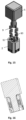
- Figure 19 in an exploded view, represents an embodiment according to the invention of the system wherein fastening the vertex cubic connector to the socket occurs with the aid of balls and springs.
- (2 ) represents the socket; (4) represents the vertex cubic connector; (5) represents a cubic central body; (9) represents the bearing; (10) represents the axial spring; (11) represents the ball axially arranged; (12) represents the ball radially arranged; (13) represents the spring radially arranged to be compressed by the action of the ball radially arranged in the socket and (14) represents a cap.
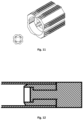
- Figure 20 represents an embodiment of the socket, the hole that will receive the spring arranged to compress by the action of the radial ball being visible.
- Figure 21 represents a side view of an embodiment of the socket, the hole that will receive the spring arranged to compress by the action of the radial ball being visible.
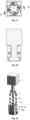
- Figure 22 represents an embodiment of the system inserted inside the rod and the detail of the radial and/or axial holes each used to house the ball and spring.
Landscapes
- Engineering & Computer Science (AREA)
- General Engineering & Computer Science (AREA)
- Mechanical Engineering (AREA)
- Mutual Connection Of Rods And Tubes (AREA)
Claims (15)
- Verbindungssystem, umfassend mindestens einen würfelförmigen Eckverbinder (4), mindestens eine Buchse (2) mit einem Hohlraum zur Aufnahme eines Bolzens (6) des genannten Verbinders und mindestens eine Stange mit einem hohlen Ende zur Aufnahme und Befestigung der genannten Buchse (2) in direktem und kontinuierlichem Längskontakt zwischen der Buchse (2) und dem hohlen Ende der Stange;wobei der würfelförmige Eckverbinder (4) mindestens einen Bolzen zum Einsetzen und Drehen in dem genannten Hohlraum aufweist;wobei der genannte Bolzen (6) aus einer Würfelseite des genannten würfelförmigen Verbinders (4) herausragt;wobei der genannte Bolzen (6) einen oder mehrere Stifte (7) an einem von der genannten Seite entfernten Ende aufweist;wobei die genannten Stifte radial von dem genannten Bolzen (6) abstehen;wobei die genannte Buchse Längsnuten (8) umfasst, die in dem Hohlraum so angeordnet sind, dass die genannten Stifte (7) in diesen gleiten, und wobei die Nuten (8) in Auflageflächen enden, um die Stifte zu halten, wenn der Bolzen (6) relativ zu der Buchse (2) gedreht wird;wobei die Buchse (2) und der Bolzen (6) so konfiguriert sind, dass die genannte Fläche direkt an das Ende der Stange anstößt, wenn der würfelförmige Verbinder in der Buchse und die Buchse in der Stange montiert ist;dadurch gekennzeichnet, dass die Buchse (2) mindestens eine Kugel (11, 12) und eine Feder (10, 13) umfasst, die axial und/oder radial so angeordnet ist, dass die Kugel (11, 12) gegen einen Stift (3) des würfelförmigen Eckverbinders gedrückt wird, um den Stift (3) zurückzuhalten, nachdem der Stift (3) durch die Kugel (11, 12) hindurchgeführt worden ist, um die Drehung des Verbinders in Bezug auf die entsprechende Buchse zu unterbrechen.
- Verbindungssystem nach dem vorangehenden Anspruch, wobei die genannte Buchse (2) eine oder mehrere Längskerben für einen direkten und kontinuierlichen Kontakt mit dem genannten Hohlraum entlang der genannten Buchse aufweist.
- Verbindungssystem nach einem der vorangehenden Ansprüche, wobei der Bolzen (6) zylinderförmig ist.
- Verbindungssystem nach einem der vorangehenden Ansprüche, wobei die Stangen hohle Rohre oder massive Stangen mit hohlen Enden zur Aufnahme der genannten Buchse (2) sind.
- Verbindungssystem nach einem der vorangehenden Ansprüche, wobei die Auflagefläche (9) eine ebene Fläche aufweist, auf die ein Vorsprung folgt, auf den eine Aussparung folgt, auf die ein Anschlag folgt, um den entsprechenden Stift nach dem Durchführen durch den Vorsprung zurückzuhalten, wenn der Bolzen (6) in den genannten Hohlraum der Buchse (2) eingesetzt und gedreht wird.
- Verbindungssystem nach einem der vorangehenden Ansprüche, wobei die Buchse (2) eine oder mehrere axiale Öffnungen aufweist, um jeweils eine Kugel (11) und eine Feder (10) aufzunehmen, und/oder die Buchse (2) eine oder mehrere radiale Öffnungen aufweist, um jeweils eine Kugel (12) und eine Feder (13) aufzunehmen.
- Verbindungssystem nach einem der vorangehenden Ansprüche, wobei der Hohlraum eine Öffnung durch die Buchse (2) ist.
- Verbindungssystem nach einem der vorangehenden Ansprüche, wobei der Bolzen (6) zwei Stifte, bevorzugt drei Stifte, besonders bevorzugt vier Stifte umfasst.
- Verbindungssystem nach einem der vorangehenden Ansprüche, wobei der würfelförmige Eckverbinder ein monolithisches Bauteil ist und/oder wobei die Buchse (2) ein monolithisches Bauteil ist.
- Verbindungssystem nach einem der vorangehenden Ansprüche, wobei die Buchse und der würfelförmige Eckverbinder (4) aus Metall gefertigt sind.
- Verbindungssystem nach einem der vorangehenden Ansprüche, wobei der würfelförmige Verbinder (4) für ein Verbindungsende zweier Stangen in einem Winkel von 90° oder 180° zueinander vorgesehen ist, und wobei der genannte würfelförmige Verbinder zwei in einem Winkel von 90° oder 180° zueinander stehende Bolzen umfasst, von denen jeder aus einer entsprechenden Würfelseite des genannten würfelförmigen Verbinders herausragt, und/oder wobei der würfelförmige Verbinder (4) für ein Verbindungsende dreier in einem Winkel von 90° zueinander stehenden Stangen vorgesehen ist, und wobei der genannte würfelförmige Verbinder drei in einem Winkel von 90° zueinander stehende Bolzen umfasst, von denen jeder aus einer entsprechenden Würfelseite des genannten würfelförmigen Verbinders herausragt, oder wobei der würfelförmige Verbinder für ein Verbindungsende von vier in einem Winkel von 90° zueinander stehenden Stangen vorgesehen ist, und wobei der genannte würfelförmige Verbinder (4) vier in einem Winkel von 90° zueinander stehende Bolzen umfasst, von denen jeder aus einer entsprechenden Würfelseite des genannten würfelförmigen Verbinders herausragt, oder wobei der würfelförmige Verbinder für ein Verbindungsende von fünf in einem Winkel von 90° zueinander stehenden Stangen vorgesehen ist, und wobei der genannte würfelförmige Verbinder fünf in einem Winkel von 90° zueinander stehende Bolzen umfasst, von denen jeder aus einer entsprechenden Würfelseite des genannten würfelförmigen Verbinders herausragt oder wobei der würfelförmige Verbinder (4) für ein Verbindungsende von sechs in einem Winkel von 90° zueinander stehenden Stangen vorgesehen ist, und wobei der genannte würfelförmige Verbinder sechs in einem Winkel von 90° zueinander stehende Bolzen umfasst, von denen jeder aus einer entsprechenden Würfelseite des genannten würfelförmigen Verbinders herausragt.
- Verfahren zum Zusammenbau des Verbindungssystems nach einem der vorangehenden Ansprüche, umfassend die folgenden Schritte:Translatorisches Einführen der Buchse (2) in eine Stange mit einem Hohlraum an einem Ende der Stange und Befestigen der genannten Buchse (2);Einführen des würfelförmigen Verbindungsbolzens in den Hohlraum der Buchse (2) und der Stifte in die Längsnuten des genannten Hohlraums der Buchse (2);Aufsetzen der Würfeloberfläche des würfelförmigen Verbinders (4) auf die Buchse (2) und Drehen zur Befestigung des würfelförmigen Verbinders (4).
- Verfahren nach dem vorangehenden Anspruch, wobei der würfelförmige Verbinder um 45° gedreht wird.
- Struktur, umfassend das Verbindungssystem nach einem der Ansprüche 1 bis 11, wobei die Struktur ein Möbelstück ist, wobei die Struktur bevorzugt ein Bücherregal, ein Tisch oder ein Schrank ist.
- Verfahren zur Herstellung des Verbindungssystems nach einem der Ansprüche 1 bis 11, umfassend den Schritt des Formens der genannten Buchse (2).
Applications Claiming Priority (3)
| Application Number | Priority Date | Filing Date | Title |
|---|---|---|---|
| PT11702221 | 2021-01-20 | ||
| PT11746921 | 2021-09-17 | ||
| PCT/IB2022/050482 WO2022157665A1 (en) | 2021-01-20 | 2022-01-20 | Connection system for metallic structures and assembling method thereof |
Publications (3)
| Publication Number | Publication Date |
|---|---|
| EP4281673A1 EP4281673A1 (de) | 2023-11-29 |
| EP4281673B1 true EP4281673B1 (de) | 2025-04-23 |
| EP4281673C0 EP4281673C0 (de) | 2025-04-23 |
Family
ID=80446292
Family Applications (1)
| Application Number | Title | Priority Date | Filing Date |
|---|---|---|---|
| EP22705881.5A Active EP4281673B1 (de) | 2021-01-20 | 2022-01-20 | Verbindungssystem für metallstrukturen und montageverfahren dafür |
Country Status (2)
| Country | Link |
|---|---|
| EP (1) | EP4281673B1 (de) |
| WO (1) | WO2022157665A1 (de) |
Family Cites Families (3)
| Publication number | Priority date | Publication date | Assignee | Title |
|---|---|---|---|---|
| EP1030066B1 (de) | 1999-02-18 | 2003-06-25 | Visplay International AG | Lösbare Klemmverbindung für eine Verstrebung |
| CN206129805U (zh) * | 2016-07-21 | 2017-04-26 | 厦门上特展示系统工程有限公司 | 一种适用于方管的锁固机构 |
| DE202018106526U1 (de) * | 2018-11-16 | 2018-11-28 | kosmas GmbH | Verbindungssystem und Regalsystem |
-
2022
- 2022-01-20 EP EP22705881.5A patent/EP4281673B1/de active Active
- 2022-01-20 WO PCT/IB2022/050482 patent/WO2022157665A1/en not_active Ceased
Also Published As
| Publication number | Publication date |
|---|---|
| EP4281673A1 (de) | 2023-11-29 |
| WO2022157665A1 (en) | 2022-07-28 |
| EP4281673C0 (de) | 2025-04-23 |
Similar Documents
| Publication | Publication Date | Title |
|---|---|---|
| US10415613B2 (en) | Set of panel-shaped elements for a composed element | |
| US10270198B2 (en) | Canted coil springs, connectors and related methods | |
| CN107683375A (zh) | 家具的部件之间的连接装置 | |
| WO2008097337A2 (en) | Methods and apparatus for multiple part missile | |
| US20150226257A1 (en) | Linear motion bearing with interlock structure | |
| CN117425782A (zh) | 用于镶板的机械连接布置结构 | |
| JP2016540176A (ja) | 継手 | |
| GB2147680A (en) | Connecting tube or rod members | |
| EP4281673A1 (de) | Verbindungssystem für metallstrukturen und montageverfahren dafür | |
| CN114364850A (zh) | 用于结构体或物体模块化构建的联接器 | |
| CN114109538B (zh) | 一种双层机匣孔探孔堵孔结构 | |
| CN103140691B (zh) | 带有改进的外部壳体衬套的直线轴承 | |
| US20230167846A1 (en) | Method for assembling a flexure bearing | |
| EP1296078B1 (de) | Gleichlaufgelenk | |
| US4966488A (en) | Ball retainer | |
| CN222010691U (zh) | 杆件连接组件 | |
| US20160108956A1 (en) | Linear motion bearing system with self-aligning rail | |
| EP2593687B1 (de) | Linearbewegungslager mit einer plattenhaltestruktur mit mehreren teilen | |
| CN213451184U (zh) | 一种铝合金型材及其外抱接头 | |
| US6629802B2 (en) | Method of connecting two panels of a piece of furniture and a piece of furniture utilizing such a connection | |
| CN219809233U (zh) | 一种法兰连接组件及机械臂 | |
| AU8625791A (en) | Rotational connectors | |
| JP7699829B2 (ja) | 構造材結合用ジョイント | |
| EP0530514A1 (de) | Lenkrollenaufbau | |
| US20150139572A1 (en) | Linear motion bearing with modular bearing segments |
Legal Events
| Date | Code | Title | Description |
|---|---|---|---|
| STAA | Information on the status of an ep patent application or granted ep patent |
Free format text: STATUS: UNKNOWN |
|
| STAA | Information on the status of an ep patent application or granted ep patent |
Free format text: STATUS: THE INTERNATIONAL PUBLICATION HAS BEEN MADE |
|
| PUAI | Public reference made under article 153(3) epc to a published international application that has entered the european phase |
Free format text: ORIGINAL CODE: 0009012 |
|
| STAA | Information on the status of an ep patent application or granted ep patent |
Free format text: STATUS: REQUEST FOR EXAMINATION WAS MADE |
|
| 17P | Request for examination filed |
Effective date: 20230818 |
|
| AK | Designated contracting states |
Kind code of ref document: A1 Designated state(s): AL AT BE BG CH CY CZ DE DK EE ES FI FR GB GR HR HU IE IS IT LI LT LU LV MC MK MT NL NO PL PT RO RS SE SI SK SM TR |
|
| DAV | Request for validation of the european patent (deleted) | ||
| DAX | Request for extension of the european patent (deleted) | ||
| GRAP | Despatch of communication of intention to grant a patent |
Free format text: ORIGINAL CODE: EPIDOSNIGR1 |
|
| STAA | Information on the status of an ep patent application or granted ep patent |
Free format text: STATUS: GRANT OF PATENT IS INTENDED |
|
| INTG | Intention to grant announced |
Effective date: 20241126 |
|
| GRAS | Grant fee paid |
Free format text: ORIGINAL CODE: EPIDOSNIGR3 |
|
| GRAA | (expected) grant |
Free format text: ORIGINAL CODE: 0009210 |
|
| STAA | Information on the status of an ep patent application or granted ep patent |
Free format text: STATUS: THE PATENT HAS BEEN GRANTED |
|
| AK | Designated contracting states |
Kind code of ref document: B1 Designated state(s): AL AT BE BG CH CY CZ DE DK EE ES FI FR GB GR HR HU IE IS IT LI LT LU LV MC MK MT NL NO PL PT RO RS SE SI SK SM TR |
|
| REG | Reference to a national code |
Ref country code: GB Ref legal event code: FG4D |
|
| REG | Reference to a national code |
Ref country code: CH Ref legal event code: EP |
|
| REG | Reference to a national code |
Ref country code: DE Ref legal event code: R096 Ref document number: 602022013528 Country of ref document: DE |
|
| REG | Reference to a national code |
Ref country code: IE Ref legal event code: FG4D |
|
| U01 | Request for unitary effect filed |
Effective date: 20250521 |
|
| U07 | Unitary effect registered |
Designated state(s): AT BE BG DE DK EE FI FR IT LT LU LV MT NL PT RO SE SI Effective date: 20250530 |
|
| PG25 | Lapsed in a contracting state [announced via postgrant information from national office to epo] |
Ref country code: ES Free format text: LAPSE BECAUSE OF FAILURE TO SUBMIT A TRANSLATION OF THE DESCRIPTION OR TO PAY THE FEE WITHIN THE PRESCRIBED TIME-LIMIT Effective date: 20250423 |
|
| PG25 | Lapsed in a contracting state [announced via postgrant information from national office to epo] |
Ref country code: GR Free format text: LAPSE BECAUSE OF FAILURE TO SUBMIT A TRANSLATION OF THE DESCRIPTION OR TO PAY THE FEE WITHIN THE PRESCRIBED TIME-LIMIT Effective date: 20250724 Ref country code: NO Free format text: LAPSE BECAUSE OF FAILURE TO SUBMIT A TRANSLATION OF THE DESCRIPTION OR TO PAY THE FEE WITHIN THE PRESCRIBED TIME-LIMIT Effective date: 20250723 |
|
| PG25 | Lapsed in a contracting state [announced via postgrant information from national office to epo] |
Ref country code: PL Free format text: LAPSE BECAUSE OF FAILURE TO SUBMIT A TRANSLATION OF THE DESCRIPTION OR TO PAY THE FEE WITHIN THE PRESCRIBED TIME-LIMIT Effective date: 20250423 |
|
| PG25 | Lapsed in a contracting state [announced via postgrant information from national office to epo] |
Ref country code: HR Free format text: LAPSE BECAUSE OF FAILURE TO SUBMIT A TRANSLATION OF THE DESCRIPTION OR TO PAY THE FEE WITHIN THE PRESCRIBED TIME-LIMIT Effective date: 20250423 |
|
| PG25 | Lapsed in a contracting state [announced via postgrant information from national office to epo] |
Ref country code: RS Free format text: LAPSE BECAUSE OF FAILURE TO SUBMIT A TRANSLATION OF THE DESCRIPTION OR TO PAY THE FEE WITHIN THE PRESCRIBED TIME-LIMIT Effective date: 20250723 |
|
| PG25 | Lapsed in a contracting state [announced via postgrant information from national office to epo] |
Ref country code: IS Free format text: LAPSE BECAUSE OF FAILURE TO SUBMIT A TRANSLATION OF THE DESCRIPTION OR TO PAY THE FEE WITHIN THE PRESCRIBED TIME-LIMIT Effective date: 20250823 |
|
| PG25 | Lapsed in a contracting state [announced via postgrant information from national office to epo] |
Ref country code: SM Free format text: LAPSE BECAUSE OF FAILURE TO SUBMIT A TRANSLATION OF THE DESCRIPTION OR TO PAY THE FEE WITHIN THE PRESCRIBED TIME-LIMIT Effective date: 20250423 |
|
| PG25 | Lapsed in a contracting state [announced via postgrant information from national office to epo] |
Ref country code: CZ Free format text: LAPSE BECAUSE OF FAILURE TO SUBMIT A TRANSLATION OF THE DESCRIPTION OR TO PAY THE FEE WITHIN THE PRESCRIBED TIME-LIMIT Effective date: 20250423 |
|
| U20 | Renewal fee for the european patent with unitary effect paid |
Year of fee payment: 5 Effective date: 20251217 |
|
| PG25 | Lapsed in a contracting state [announced via postgrant information from national office to epo] |
Ref country code: SK Free format text: LAPSE BECAUSE OF FAILURE TO SUBMIT A TRANSLATION OF THE DESCRIPTION OR TO PAY THE FEE WITHIN THE PRESCRIBED TIME-LIMIT Effective date: 20250423 |
|
| REG | Reference to a national code |
Ref country code: CH Ref legal event code: U11 Free format text: ST27 STATUS EVENT CODE: U-0-0-U10-U11 (AS PROVIDED BY THE NATIONAL OFFICE) Effective date: 20260201 |
|
| PLBE | No opposition filed within time limit |
Free format text: ORIGINAL CODE: 0009261 |
|
| STAA | Information on the status of an ep patent application or granted ep patent |
Free format text: STATUS: NO OPPOSITION FILED WITHIN TIME LIMIT |
|
| REG | Reference to a national code |
Ref country code: CH Ref legal event code: L10 Free format text: ST27 STATUS EVENT CODE: U-0-0-L10-L00 (AS PROVIDED BY THE NATIONAL OFFICE) Effective date: 20260304 |
|
| 26N | No opposition filed |
Effective date: 20260126 |
|
| PGFP | Annual fee paid to national office [announced via postgrant information from national office to epo] |
Ref country code: GB Payment date: 20260126 Year of fee payment: 5 |
|
| PGFP | Annual fee paid to national office [announced via postgrant information from national office to epo] |
Ref country code: IE Payment date: 20260120 Year of fee payment: 5 |
|
| PGFP | Annual fee paid to national office [announced via postgrant information from national office to epo] |
Ref country code: CH Payment date: 20260201 Year of fee payment: 5 |