EP4281296B1 - Fahrzeugluftreifen - Google Patents
Fahrzeugluftreifen Download PDFInfo
- Publication number
- EP4281296B1 EP4281296B1 EP21823754.3A EP21823754A EP4281296B1 EP 4281296 B1 EP4281296 B1 EP 4281296B1 EP 21823754 A EP21823754 A EP 21823754A EP 4281296 B1 EP4281296 B1 EP 4281296B1
- Authority
- EP
- European Patent Office
- Prior art keywords
- groove
- groove portion
- section
- pneumatic vehicle
- vehicle tyre
- Prior art date
- Legal status (The legal status is an assumption and is not a legal conclusion. Google has not performed a legal analysis and makes no representation as to the accuracy of the status listed.)
- Active
Links
Images

Classifications
-
- B—PERFORMING OPERATIONS; TRANSPORTING
- B60—VEHICLES IN GENERAL
- B60C—VEHICLE TYRES; TYRE INFLATION; TYRE CHANGING; CONNECTING VALVES TO INFLATABLE ELASTIC BODIES IN GENERAL; DEVICES OR ARRANGEMENTS RELATED TO TYRES
- B60C11/00—Tyre tread bands; Tread patterns; Anti-skid inserts
- B60C11/03—Tread patterns
- B60C11/0302—Tread patterns directional pattern, i.e. with main rolling direction
-
- B—PERFORMING OPERATIONS; TRANSPORTING
- B60—VEHICLES IN GENERAL
- B60C—VEHICLE TYRES; TYRE INFLATION; TYRE CHANGING; CONNECTING VALVES TO INFLATABLE ELASTIC BODIES IN GENERAL; DEVICES OR ARRANGEMENTS RELATED TO TYRES
- B60C11/00—Tyre tread bands; Tread patterns; Anti-skid inserts
- B60C11/03—Tread patterns
- B60C2011/0337—Tread patterns characterised by particular design features of the pattern
- B60C2011/0339—Grooves
- B60C2011/0358—Lateral grooves, i.e. having an angle of 45 to 90 degees to the equatorial plane
-
- B—PERFORMING OPERATIONS; TRANSPORTING
- B60—VEHICLES IN GENERAL
- B60C—VEHICLE TYRES; TYRE INFLATION; TYRE CHANGING; CONNECTING VALVES TO INFLATABLE ELASTIC BODIES IN GENERAL; DEVICES OR ARRANGEMENTS RELATED TO TYRES
- B60C11/00—Tyre tread bands; Tread patterns; Anti-skid inserts
- B60C11/03—Tread patterns
- B60C2011/0337—Tread patterns characterised by particular design features of the pattern
- B60C2011/0339—Grooves
- B60C2011/0358—Lateral grooves, i.e. having an angle of 45 to 90 degees to the equatorial plane
- B60C2011/0365—Lateral grooves, i.e. having an angle of 45 to 90 degees to the equatorial plane characterised by width
-
- B—PERFORMING OPERATIONS; TRANSPORTING
- B60—VEHICLES IN GENERAL
- B60C—VEHICLE TYRES; TYRE INFLATION; TYRE CHANGING; CONNECTING VALVES TO INFLATABLE ELASTIC BODIES IN GENERAL; DEVICES OR ARRANGEMENTS RELATED TO TYRES
- B60C11/00—Tyre tread bands; Tread patterns; Anti-skid inserts
- B60C11/03—Tread patterns
- B60C2011/0337—Tread patterns characterised by particular design features of the pattern
- B60C2011/0339—Grooves
- B60C2011/0358—Lateral grooves, i.e. having an angle of 45 to 90 degees to the equatorial plane
- B60C2011/0367—Lateral grooves, i.e. having an angle of 45 to 90 degees to the equatorial plane characterised by depth
-
- B—PERFORMING OPERATIONS; TRANSPORTING
- B60—VEHICLES IN GENERAL
- B60C—VEHICLE TYRES; TYRE INFLATION; TYRE CHANGING; CONNECTING VALVES TO INFLATABLE ELASTIC BODIES IN GENERAL; DEVICES OR ARRANGEMENTS RELATED TO TYRES
- B60C11/00—Tyre tread bands; Tread patterns; Anti-skid inserts
- B60C11/03—Tread patterns
- B60C2011/0337—Tread patterns characterised by particular design features of the pattern
- B60C2011/0339—Grooves
- B60C2011/0358—Lateral grooves, i.e. having an angle of 45 to 90 degees to the equatorial plane
- B60C2011/0367—Lateral grooves, i.e. having an angle of 45 to 90 degees to the equatorial plane characterised by depth
- B60C2011/0369—Lateral grooves, i.e. having an angle of 45 to 90 degees to the equatorial plane characterised by depth with varying depth of the groove
-
- B—PERFORMING OPERATIONS; TRANSPORTING
- B60—VEHICLES IN GENERAL
- B60C—VEHICLE TYRES; TYRE INFLATION; TYRE CHANGING; CONNECTING VALVES TO INFLATABLE ELASTIC BODIES IN GENERAL; DEVICES OR ARRANGEMENTS RELATED TO TYRES
- B60C11/00—Tyre tread bands; Tread patterns; Anti-skid inserts
- B60C11/03—Tread patterns
- B60C2011/0337—Tread patterns characterised by particular design features of the pattern
- B60C2011/0339—Grooves
- B60C2011/0358—Lateral grooves, i.e. having an angle of 45 to 90 degees to the equatorial plane
- B60C2011/0372—Lateral grooves, i.e. having an angle of 45 to 90 degees to the equatorial plane with particular inclination angles
Definitions
- the invention relates to a pneumatic vehicle tire with a directional tread having at least one central row of tread blocks delimited on both sides by circumferential grooves with tread blocks which are separated from one another by transverse grooves which, in plan view, run parallel to one another and open into the circumferential grooves and each have a groove center line, two groove flanks and a groove bottom, wherein the transverse grooves each have a first groove section which opens into one of the circumferential grooves and runs at an angle of 5° to 25° to the axial direction and with respect to the groove center line, and a second groove section which adjoins this first groove section and is inclined in the axial direction in the opposite direction to the first groove section, wherein the groove sections first enter the ground with their mutual connection area when the tire rolls during forward travel, wherein in each tread block there is formed an additional groove which, in plan view, runs in extension of the first groove section and is narrower than the first groove section and extends between the transverse groove and the other of the two circumferential grooves.
- Such a pneumatic vehicle tire is known, for example, from US 5 287 905 A
- This pneumatic vehicle tire has, according to one embodiment, a directional tread pattern with two central tread block rows, each bordered on both sides by circumferential grooves, with transverse grooves and tread blocks merging into the circumferential grooves.
- the transverse grooves are each composed of a first groove section extending at an angle of approximately 15° to the axial direction and merging into one circumferential groove, a second groove section adjoining the first groove section and inclined in the opposite direction to the axial direction, and a third groove section inclined in the same direction to the first groove section and merging into the other circumferential groove.
- a narrow additional groove is formed as an extension of the first groove section and as an extension of the second groove section. The tire should exhibit low tire-road noise while maintaining good dry performance.
- a pneumatic vehicle tire which – with the exception of the directional nature of the tread – corresponds to a pneumatic vehicle tire of the type mentioned above.
- the tread has four tread ribs, with one of the center ribs being significantly wider than the other ribs.
- the wider, center rib is provided with a groove pattern consisting of intersecting transverse grooves and additional grooves.
- the pneumatic vehicle tire is intended to exhibit good snow performance and good response to steering forces.
- a pneumatic vehicle tire is known with a tread having two central rows of tread blocks, each delimited by circumferential grooves and divided into tread blocks by transverse grooves, wherein the transverse grooves widen in a funnel shape towards the shoulder-side circumferential groove.
- the transverse grooves have two groove sections adjoining one another at an obtuse angle, wherein a base elevation is formed in the end section of one groove section on the inside of the block.
- an additional groove is formed running between adjacent transverse grooves, which divides the respective tread block into two essentially equal-sized block segments, wherein the additional groove widens in a funnel shape and runs at an angle of 5° to 15° to the circumferential direction.
- the tread is designed to be directional. This tire is intended to be suitable as an all-season tire and is particularly balanced with regard to its handling characteristics, which are primarily determined by the stiffness of the tread, the water drainage capacity and the snow grip.
- the transverse grooves formed on the tread which have at least a bend in their course due to their groove sections, are primarily responsible for good snow grip properties, especially when cornering.
- the groove sections lengthen the drainage path to the circumferential grooves and increase the risk of turbulence in the flowing water, so that the water drainage capacity of the transverse grooves is reduced compared to kink-free transverse grooves.
- EP 3 300 926 A1 Known additional grooves formed in the tread blocks cannot compensate to the desired extent for the reduced water drainage capacity caused by the angled groove sections.
- the invention is therefore based on the object of implementing measures in a pneumatic vehicle tire of the type mentioned at the outset which optimally compensate for the reduced water drainage capacity of the transverse grooves, which is caused by the angled "drainage paths" in aquaplaning situations, while maintaining a profile stiffness required for good handling properties.
- the additional groove is designed to be shallower than the first groove section, wherein the groove base of the transverse groove has a base section extending over the entire second groove section, which projects into the first groove section with an end section and is provided with a local depression reaching as far as the groove flanks, which is formed at least partially in the end section or adjacent to the end section, wherein the transverse groove is designed to be shallowest in the region of the base section outside the local depression.
- additional grooves are therefore specifically tailored to the directional nature of the tread. Since these additional grooves extend from the first groove section, water absorbed by the additional grooves is diverted with minimal turbulence into the first groove section of the transverse groove and from there into the circumferential groove into which this groove section opens, significantly increasing water drainage capacity.
- the additional grooves are narrower and shallower than the first groove section, the rigidity of the tread blocks, which is crucial for good handling characteristics, is maintained.
- the locally shallower transverse grooves stiffen the row of tread blocks and are thus beneficial for handling characteristics.
- the local deepening increases the volume of the transverse groove or the transverse groove cross-section in the area where the additional groove joins, i.e., in the critical area for water drainage.
- the additional groove viewed in plan view and relative to its groove centerline, extends at an angle to the axial direction that deviates from the angle at which the first groove section extends to the axial direction by at most 10°, in particular by at most 5°, and particularly preferably by at most 2°.
- This measure contributes to quickly diverting water absorbed by the additional groove into the first groove section of the transverse groove and is therefore of additional benefit for the water drainage capacity in the region of the transverse groove.
- first groove edge viewed in plan view, runs in a straight line extension of the block edge section located in the first groove section, to which it adjoins.
- the additional groove has a depth of 1.0 mm to 2.0 mm, in particular 1.3 mm to 1.7 mm, and/or a width of 1.0 mm to 2.0 mm, in particular 1.3 mm to 1.7 mm, in the radial direction.
- the second groove section forms an angle of 100° to 130°, preferably 110° to 120°, particularly preferably 113° to 117°, with the first groove section, relative to the groove center line.
- the local depression - in relation to its volume - is formed at least largely in the second groove section.
- the local depression has a depth of 0.5 mm to 1.5 mm, in particular of 0.8 mm to 1.2 mm, and/or a length of 1.5 mm to 4.0 mm determined along the groove center line.
- the end section of the base section - relative to the groove center line m QR - has a length projected in the axial direction of 40% to 60%, in particular of at least 50%, of the length of the first groove section determined in an analogous manner.
- a deeper The junction area with the circumferential groove which ensures a particularly advantageous balance between the rigidity of the tread block row and the water drainage capacity of the transverse grooves running within it.
- the base section extends outside the local depression at a constant depth of 40% to 60% of the profile depth, determined in the radial direction. This contributes to the balance of the aforementioned properties.
- the groove base of the transverse groove has a base section that runs exclusively in the first groove section, which is at most 1.0 mm to 2.0 mm from the tread depth level in the radial direction and preferably slopes downwards toward the circumferential groove into which the first groove section opens.
- This base section is located in the aforementioned, deeper junction area of the transverse groove with the circumferential groove and is advantageous for the water drainage capacity of the transverse groove.
- the second groove section extends to the circumferential groove into which the first groove section does not open.
- the third groove section gives the transverse groove a zigzag shape and is particularly beneficial for snow grip.
- the third groove section advantageously enhances the water drainage capacity of the transverse groove due to the specially designed additional grooves, which, as explained in the context of the solution to the problem, have little impact.
- the additional grooves primarily increase the ingress of water into the first groove section, while the third groove section connects to the second groove section.
- the first groove section opens into a circumferential groove that borders the middle row of tread blocks on the outside of the tread and the additional groove opens into a circumferential groove that borders the middle row of tread blocks on the inside of the tread.
- Pneumatic vehicle tires designed according to the invention are tires for motor vehicles, in particular for multi-track motor vehicles, and preferably tires of radial design for passenger cars, vans or light trucks (light trucks with a GVW ⁇ 7.5 t), the tires being intended for driving under winter driving conditions.
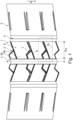
- Fig. 1 shows a circumferential section of a tread 1 of a pneumatic vehicle tire.
- the tread 1 has a directional tread pattern, and the pneumatic vehicle tire is to be mounted on the vehicle in such a way that it has the rolling direction symbolized by the arrow R when driving forward.
- the tire's equatorial plane is indicated by a dashed line AA.
- the tread 1 has in each tread half a central tread block row 2 and a shoulder-side tread rib 3, wherein the shoulder-side tread ribs 3 are only shown schematically and can be designed in a manner known per se.
- the central tread block rows 2 are separated from each other by a central circumferential groove 4 which runs straight in plan view and along the tire equatorial plane (line AA), and from the respectively adjacent shoulder-side tread rib 3 by a shoulder-side tread groove 4 which runs straight in plan view.
- the circumferential grooves 4, 5 are in the respective intended profile depth T P ( Fig. 3 , Fig. 7 ), which is usually 6.5 mm to 13.0 mm for the preferred tire type.
- Each central tread block row 2 has a width b PB at the tread periphery in the axial direction and is divided into tread blocks 6 by a plurality of transverse grooves 7, which in the exemplary embodiment are zigzag-shaped and parallel to one another in plan view and which run between the central circumferential groove 4 and the corresponding shoulder-side circumferential groove 5.
- the transverse grooves 7 are formed in the central tread block rows 2 in such a way that one central tread block row 2 is symmetrical to the other central tread block row 2 with respect to the tire equatorial plane (line AA).
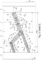
- the further design of the tread blocks 6 and the transverse grooves 7 is described below using an individual transverse groove 7 and the tread blocks 6 adjacent to the transverse groove 7 and with reference to Fig. 2 to Fig. 8 explained.
- the transverse groove 7 is composed of a groove section 7a leading into the shoulder-side circumferential groove 5, a groove section 7b ending on both sides within the middle tread block row 2, and a groove section 7c leading into the central circumferential groove 4.
- the groove center line m QR following the groove course (coincides with the section line VII-VII) is shown.
- the groove section 7a runs straight in plan view and - with respect to the groove center line m QR - at an angle ⁇ of 5° to 25°, in particular of 10° to 20°, preferably of 13° to 17°, to the axial direction and has a length l a projected in the axial direction and with respect to the groove center line m QR of 40% to 60%, in particular of 45% to 55%, of the width b PB of the middle profile block row 2.
- the groove section 7b runs straight when viewed from above, is inclined in the opposite direction to the groove section 7a with respect to the axial direction and encloses with it - based on the groove center line m QR - an angle ⁇ of 100° to 130°, preferably of 110° to 120°, particularly preferably of 113° to 117°.
- the inclination of the groove sections 7a, 7b is such that when the tire rolls forward (arrow R), the adjacent, block-inside ends of the groove sections 7a, 7b penetrate the ground before the other ends.
- the groove sections 7a, 7b therefore penetrate the ground via their mutual connecting area.
- the groove section 7c also runs straight when viewed from above, is inclined in the same direction as the groove section 7a with respect to the axial direction, runs - with respect to the groove center line m QR - at an angle ⁇ to the axial direction, which deviates from the angle ⁇ of the groove section 7a by a maximum of 5°, encloses an obtuse angle ⁇ with the groove section 7b - with respect to the groove center line m QR - and has a length l c projected in the axial direction, related to the groove center line m QR , of 15% to 30%, in particular of 20% to 25%, of the width b PB of the middle profile block row 2.
- the profile blocks 6 each have adjacent transverse grooves 7 (in Fig. 2
- the tread pattern has a block edge 9 on one side (shown for a transverse groove 7) and a block edge 10 on the other adjacent transverse groove 7, whereby when the tire rolls forward (arrow R), the block edge 9 of each tread block 6 enters the ground before the block edge 10.
- the block edge 9 is therefore also referred to below as the "incoming block edge 9" and the block edge 10 is also referred to below as the "outgoing block edge 10".
- the block edges 9, 10 are each composed of a block edge section 9a, 10a running in the groove section 7a, a block edge section 9b, 10b running in the groove section 7b and a block edge section 9c, 10c running in the groove section 7c, whereby the block edge sections 9a, 9b, 9c, 10a, 10b, 10c each run straight in plan view.
- the transverse groove 7 has a width b QR determined between the block edges 9, 10 or between the corresponding block edge sections 9a, 9b, 9c, 10a, 10b, 10c in plan view perpendicular to the groove center line m QR .
- the width b QR decreases continuously from the end of the groove section 7a located inside the tread block row 2 in the direction of the shoulder-side circumferential groove 5 over the extent of the block edge sections 9a, 10a, wherein the width b QR in the groove section 7a at the narrowest point Sa ,min is 2.5 mm to 4.0 mm, in particular 3.5 mm to 4.5 mm, and at the widest point Sa ,max is 110% to 130%, in particular 115% to 125%, of the width b QR at the narrowest point Sa ,min .
- the width b QR decreases continuously in the direction of the groove section 7c, wherein the width b QR in the groove section 7b at the narrowest point S b,min is 85% to 95% of the width b QR at the point S a,min .
- the width b QR is constant and smaller than at the point S b,min and is at least 1.5 mm, preferably at least 2.0 mm.
- the transverse groove 7 is delimited over all groove sections 7a, 7b, 7c by a groove flank 11 extending from the incoming block edge 9, a groove flank 12 extending from the outgoing block edge 10 and a groove base 13.
- the groove flanks 11, 12, viewed in the cross-section oriented perpendicular to the groove center line m QR extend to the radial direction at an angle ⁇ ( Fig. 4 to Fig. 6 ) from 0° to 7°, whereby the angle ⁇ of the groove flanks 11, 12 in the groove sections 7a, 7b ( Fig. 4, Fig. 5 ) preferably up to 5° and in the groove section 7c ( Fig. 6 ) is preferably up to 3°.
- the groove base 13 has a base section 13', which extends over the groove sections 7c, 7b and projects into the groove section 7a with an end section 13'a, and a base section 13" which runs exclusively in the groove section 7a.
- the base section 13' is provided in the groove section 7b with a local depression 14 which is trapezoidal in plan view and borders on the end section 13'a.
- the local depression 14 (cf. Fig. 7 ) be formed at least partially in the end section 13'a.
- the end section 13'a has - relative to the groove center line m QR - a length l' a projected in the axial direction of 40% to 60%, in particular of at least 50%, of the length l a of the groove section 7a.
- the recess 14 has a depth tv of 0.5 mm to 1.5 mm, in particular of 0.8 mm to 1.2 mm, compared to the level of the base section 13' in the radial direction, as well as a length Iv determined along the groove center line m QR at the level of the base section 13'a (cf. position of the section line VII-VII in Fig. 2 ) from 1.5 mm to 4.0 mm.
- the base section 13 which runs exclusively in the groove section 7a, has, in its area closest to the end section 13'a of the base section 13', a distance a 1 of 1.0 mm to 2.0 mm, determined in the radial direction, from the level of the tread depth and drops in the direction of the shoulder-side circumferential groove 5 to the tread depth T P .
- Fig. 1 further shows, in each profile block 6 an additional groove 8 is formed running between a transverse groove 7 and the central circumferential groove 4, wherein the additional grooves 8 located within a central profile block row 2 run parallel to each other in plan view.
- the additional groove 8 viewed in plan view, runs straight and in extension of the groove section 7a and opens into the groove section 7b.
- the additional groove 8 has a groove center line m N and, on the periphery of the associated profile block 6, two groove edges 8a, 8b which, viewed in plan view, run straight and parallel to one another, wherein the groove edge 8a adjoins the end of the block edge section 10a located inside the profile block 6 and wherein the groove edge 8b meets the block edge section 10b.
- the additional groove 8 viewed in plan view and relative to a groove center line m N , runs to the axial direction at an angle ⁇ ' which deviates from the angle ⁇ of the first groove section 7a by at most 10°, in particular by at most 5°, particularly preferably by at most 2°.
- the angle ⁇ ' between the groove center line m N and the axial direction is selected such that the groove edge 8a in plan view is kink-free at the Block edge section 10a and therefore runs in a straight line continuation from it.
- the additional groove 8 viewed in cross-section, is U-shaped and has a width b N determined between and in plan view perpendicular to the groove edges 8a, 8b (cf. Fig. 2 ) of 1.0 mm to 2.0 mm, in particular of 1.3 mm to 1.7 mm, a depth t N determined in the radial direction of 1.0 mm to 2.0 mm, in particular of 1.3 mm to 1.7 mm, as well as two groove flanks 8c extending from the groove edges 8a, 8b, which, viewed in the cross-section of the additional groove 8, run at an angle ⁇ of 0° to 6°, in particular of at least 2°, to the radial direction.
- the additional groove 8 is therefore narrower and shallower over its entire extent than the groove section 7a.
- the groove flank 12 of the transverse groove 7, which adjoins the outgoing block edge 10, runs in the groove section 7a at an angle ⁇ ( Fig. 4 ) and therefore has a groove flank section 12a ( Fig. 2 ).
- the angle ⁇ of the groove flank section 12a corresponds to the angle ⁇ ( Fig. 8 ) of the groove flank 8c adjoining the groove edge 8a, so that this groove flank 8c runs in a planar continuation of the groove flank section 12a, thus merging into it without kinks.
- the additional grooves 8 divide the profile blocks 6 into a block segment 6a and a block segment 6b having a smaller outer surface than the latter.
- the block segment 6a is formed by sections of the circumferential grooves 4, 5, an additional groove 8, and the groove section 7a adjoining it (cf. Fig. 2 ) and the corresponding transverse groove 7.
- the block segment 6b is bounded by a section of the central circumferential groove 4, the groove sections 7b, 7c of a transverse groove 7 (cf. Fig. 2 ) and the corresponding additional groove 8.
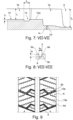
- Fig. 9 shows a view of profile blocks 6, which is a variant of the profile block 6 according to the first embodiment (cf. Fig. 1 ) and differ from the This can be distinguished in that three incisions 15a are formed in the block segment 6a and one incision 15b is formed in the block segment 6b.
- the incisions 15a run in the opposite direction to the additional groove 8 when viewed in plan view and in relation to the axial direction and traverse the block segment 6a.
- the incision 15b runs parallel to the additional groove 8 when viewed in plan view.
- the incisions 15a, 15b each have a width of 0.4 mm to 1.2 mm and, in the radial direction at their deepest point, a depth of 75% to 100%, in particular of up to 95%, of the profile depth T P ( Fig. 3 , Fig. 7 ).
- the transverse grooves 7 can be composed exclusively of the groove sections 7a, 7b, so that the transverse grooves, together with the groove section 7b, open into the corresponding circumferential groove.
- the groove section 7c is thus optional.
- the transverse grooves 7 can have a constant width.
- the additional groove 8 can open into the transverse groove 7, more precisely the groove section 7b, as an extension of the groove section 7a, such that the additional groove 8 interrupts the block edge section 10b at its end section located at the block edge section 10, and therefore both groove edges 8a, 8b adjoin the block edge section 10b.
- the groove edge 8a does not adjoin the end of the block edge section 10a.
- the tread has at least one central tread block row, which is provided with transverse grooves and additional grooves in the manner described.
Landscapes
- Engineering & Computer Science (AREA)
- Mechanical Engineering (AREA)
- Tires In General (AREA)
Description
- Die Erfindung betrifft einen Fahrzeugluftreifen mit einem laufrichtungsgebunden ausgeführten Laufstreifen mit zumindest einer beidseitig von Umfangsrillen begrenzten mittleren Profilblockreihe mit Profilblöcken, welche durch in Draufsicht parallel zueinander verlaufende, in die Umfangsrillen einmündende Querrillen mit je einer Rillenmittellinie, zwei Rillenflanken und einem Rillengrund voneinander getrennt sind, wobei die Querrillen jeweils einen in die eine der Umfangsrillen einmündenden, zur axialen Richtung und bezogen auf die Rillenmittellinie unter einem Winkel von 5° bis 25° verlaufenden, ersten Rillenabschnitt und einen an diesen anschließenden, zur axialen Richtung gegensinnig zum ersten Rillenabschnitt geneigten zweiten Rillenabschnitt aufweisen, wobei die Rillenabschnitte beim Abrollen des Reifens bei Vorwärtsfahrt mit ihrem gegenseitigen Anschlussbereich zuerst in den Untergrund eintreten, wobei in jedem Profilblock eine in Draufsicht in Verlängerung des ersten Rillenabschnittes verlaufende, gegenüber diesem schmäler ausgeführte Zusatznut ausgebildet ist, welche sich zwischen der Querrille und der anderen der beiden Umfangsrillen erstreckt.
- Ein derartiger Fahrzeugluftreifen ist beispielsweise aus der
US 5 287 905 A bekannt. Dieser Fahrzeugluftreifen weist gemäß einer Ausführungsform eine laufrichtungsgebundene Profilierung mit zwei, jeweils beidseitig von Umfangsrillen begrenzten, mittleren Profilblockreihen mit in die Umfangsrillen einmündenden Querrillen und Profilblöcken auf. Die Querrillen setzen sich, in Draufsicht betrachtet, jeweils aus einem zur axialen Richtung unter einem Winkel von zirka 15° verlaufenden, in die eine Umfangsrille einmündenden, ersten Rillenabschnitt, einem an diesen anschließenden und zu diesem bezüglich der axialen Richtung gegensinnig geneigten, zweiten Rillenabschnitt und einem zum ersten Rillenabschnitt bezüglich der axialen Richtung gleichsinnig geneigten, in die andere Umfangsrille einmündenden, dritten Rillenabschnitt zusammen. In jedem Profilblock ist in Verlängerung des ersten Rillenabschnittes bzw. in Verlängerung des zweiten Rillenabschnittes jeweils eine schmale Zusatznut ausgebildet. Der Reifen soll unter Aufrechterhaltung einer guten Trockenperformance ein geringes Reifen-Fahrbahn-Geräusch aufweisen. - Aus der
US 2020/0376899 A1 ist ein Fahrzeugluftreifen bekannt, welcher - mit Ausnahme der Laufrichtungsgebundenheit des Laufstreifens - einem Fahrzeugluftreifen der eingangs genannten Art entspricht. Der Laufstreifen weist vier Profilrippen auf, wobei eine der mittleren Profilrippen deutlich breiter als die weiteren Profilrippen ausgeführt ist. Die breiter ausgeführte, mittlere Profilrippe ist mit einem Rillenmuster aus sich kreuzenden Querrillen und Zusatzrillen versehen. Der Fahrzeugluftreifen soll eine gute Schneeperformance und ein gutes Ansprechverhalten auf Lenkkräfte aufweisen. - Aus der
EP 3 300 926 A1 ist ein Fahrzeugluftreifen mit einem Laufstreifen mit zwei mittleren Profilblockreihen bekannt, welche jeweils durch Umfangsrillen begrenzt und durch Querrillen in Profilblöcke gegliedert sind, wobei sich die Querrillen in Richtung zur schulterseitigen Umfangsrille trichterförmig verbreitern. Die Querrillen weisen zwei unter einem stumpfen Winkel aneinander anschließende Rillenabschnitte auf, wobei im blockinnenseitigen Endabschnitt, des einen Rillenabschnittes eine Grundanhebung ausgebildet ist. In den Profilblöcken ist jeweils einen zwischen benachbarten Querrillen verlaufende Zusatznut ausgebildet, welche den jeweiligen Profilblock in zwei im Wesentlichen gleichgroße Blocksegmente gliedert., wobei sich die Zusatznut trichterförmig verbreitert und unter einem Winkel von 5° bis 15° zur Umfangsrichtung verläuft. Gemäß einer Ausführungsvariante ist der Laufstreifen laufrichtungsgebunden ausgeführt. Dieser Reifen soll sich als Ganzjahresreifen eignen und insbesondere im Hinblick auf seine Handlingeigenschaften, welche vor allem durch die Steifigkeit des Laufstreifens bestimmt ist, das Wasserdrainagevermögen sowie den Schneegriff ausbalanciert sein. - Bei Reifen der eingangs genannten Art sind vor allem die am Laufstreifen ausgebildeten Querrillen, welche durch ihre Rillenabschnitte zumindest einen Knick in ihrem Verlauf aufweisen, für gute Schneegriffeigenschaften, insbesondere bei Kurvenfahrt, mitverantwortlich. Durch die Rillenabschnitte ist der Drainageweg zu den Umfangsrillen verlängert und die Gefahr des Entstehens von Verwirbelungen im durchströmenden Wasser erhöht, sodass das Wasserdrainagevermögen der Querrillen - gegenüber knickfreien Querrillen - reduziert ist. Die aus der
EP 3 300 926 A1 bekannten, in den Profilblöcken ausgebildeten Zusatznuten können das durch die gewinkelten Rillenabschnitte bedingte, reduzierte Wasserdrainagevermögen nicht im gewünschten Ausmaß ausgleichen. - Der Erfindung liegt daher die Aufgabe zugrunde, bei einem Fahrzeugluftreifen der ein eingangs genannten Art Maßnahmen zu setzen, die das reduzierte Wasserdrainagevermögen der Querrillen, welches in Aquaplaningsituationen durch die abgewinkelten "Drainagewege" verursacht wird, unter Beibehalten einer für gute Handlingeigenschaften erforderlichen Profilsteifigkeit optimal auszugleichen.
- Gelöst wird die gestellte Aufgabe erfindungsgemäß dadurch, dass die Zusatznut gegenüber dem ersten Rillenabschnitt seichter ausgeführt ist, wobei der Rillengrund der Querrille einen sich über den kompletten zweiten Rillenabschnitt erstreckenden Grundabschnitt aufweist, welcher mit einem Endabschnitt in den ersten Rillenabschnitt hineinragt und mit einer bis zu den Rillenflanken reichenden, lokalen Vertiefung versehen ist, welche zumindest teilweise im Endabschnitt oder angrenzend an den Endabschnitt ausgebildet ist, wobei die Querrille im Bereich des Grundabschnittes außerhalb der lokalen Vertiefung am seichtesten ausgeführt ist.
- Die Ausführung der Zusatznuten ist daher auf spezielle Weise auf die Laufrichtungsgebundenheit des Laufstreifens abgestimmt. Da diese Zusatznuten in Verlängerung des ersten Rillenabschnittes verlaufen wird von den Zusatznuten aufgenommenes Wasser verwirbelungsarm in die den ersten Rillenabschnitt der Querrille und von diesem in jene Umfangsrille abgeleitet, in welche dieser Rillenabschnitt mündet, sodass das Wasserdrainagevermögen deutlich erhöht ist.
- Da die Zusatznuten schmäler und seichter als der ersten Rillenabschnitt ausgeführt sind, bleibt die für gute Handlingeigenschaften maßgebliche Steifigkeit der Profilblöcke erhalten. Die lokal seichteren Querrillen versteifen die Profilblockreihe und sind somit für die Handlingeigenschaften von Vorteil. Die lokale Vertiefung vergrößert im Bereich der Einmündung der Zusatznut, also in dem im Hinblick auf das Wasserdrainagevermögen kritischen Bereich, das Volumen der Querrille bzw. den Querrillenquerschnitt.
- Gemäß einer bevorzugten Ausführung verläuft die Zusatznut, in Draufsicht betrachtet und bezogen auf ihre Nutmittellinie, zur axialen Richtung unter einem Winkel, welcher vom Winkel, unter welchem der erste Rillenabschnitt zur axialen Richtung verläuft, um höchstens 10°, insbesondere um höchstens 5°, besonders bevorzugt um höchstens 2°, abweicht. Diese Maßnahme trägt dazu bei, von der Zusatznut aufgenommenes Wasser schnell in den ersten Rillenabschnitt der Querrille abzuleiten und ist daher für das Wasserdrainagevermögen im Bereich der Querrille von zusätzlichem Vorteil.
- Eine weitere bevorzugte Ausführung ist dadurch gekennzeichnet,
- dass jeder Profilblock an den Querrillen eine beim Abrollen des Reifens bei Vorwärtsfahrt zuerst in den Untergrund eintretende, einlaufende Blockkante und eine auslaufende Blockkante aufweist, wobei die einlaufende Blockkante und die auslaufende Blockkante in jedem Rillenabschnitt je einen Blockkantenabschnitt aufweisen,
- wobei die Zusatznut eine erste und eine zweite Nutkante aufweist,
- wobei die erste Nutkante an den im ersten Rillenabschnitt befindlichen Blockkantenabschnitt der auslaufenden Blockkante und die zweite Nutkante an den im zweiten Rillenabschnitt befindlichen Blockkantenabschnitt der auslaufenden Blockkante anschließt.
- Durch derart verlaufende Nutkanten fließt das Wasser von der Zusatznut besonders verwirbelungsarm bzw. weitgehend verwirbelungsfrei in die Querrille, sodass die Wasserdrainage weiter verbessert ist.
- Bei der zuvor genannten bevorzugten Ausführung ist es aus den genannten Gründen von besonderem Vorteil, wenn die erste Nutkante, in Draufsicht betrachtet, in geradliniger Verlängerung des im ersten Rillenabschnittes befindlichen Blockkantenabschnittes verläuft, an welchen sie anschließt.
- Gemäß einer weiteren bevorzugten Ausführung weist die Zusatznut in radialer Richtung eine Tiefe von 1,0 mm bis 2,0 mm, insbesondere von 1,3 mm bis 1,7 mm, und/oder eine Breite von 1,0 mm bis 2,0 mm, insbesondere von 1,3 mm bis 1,7 mm, auf. Auch diese Merkmale sind für eine gute Wasserdrainage günstig.
- Für die Wasserdrainage ist es ferner günstig, wenn der zweite Rillenabschnitt mit dem ersten Rillenabschnitt - bezogen auf die Rillenmittellinie - einen Winkel von 100° bis 130°, bevorzugt von 110° bis 120°, besonders bevorzugt von 113° bis 117°, einschließt.
- Bei der zuvor genannten bevorzugten Ausführung ist es von Vorteil, wenn die lokale Vertiefung - bezogen auf ihr Volumen - zumindest Großteils im zweiten Rillenabschnitt ausgebildet ist.
- Ferner ist es bei der zuvor genannten bevorzugten Ausführung von Vorteil, wenn die lokale Vertiefung eine Tiefe von 0,5 mm bis 1,5 mm, insbesondere von 0,8 mm bis 1,2 mm, und/oder eine entlang der Rillenmittelinie ermittelte Länge von 1,5 mm bis 4,0 mm aufweist.
- Darüber hinaus ist es bei der zuvor genannten bevorzugten Ausführung günstig, wenn der Endabschnitt des Grundabschnittes - bezogen auf die Rillenmittellinie mQR - eine in die axiale Richtung projizierte Länge von 40% bis 60%, insbesondere von zumindest 50%, der auf analoge Weise ermittelten Länge des ersten Rillenabschnittes aufweist. Im Bereich außerhalb des Endabschnittes des Grundabschnittes verbleibt im ersten Rillenabschnitt ein tiefer ausgeführter Einmündungsbereich zur Umfangsrille, wodurch die Steifigkeit der Profilblockreihe und das Wasserdrainagevermögen der in ihr verlaufenden Querrillen besonders vorteilhaft ausbalanciert sind.
- Außerdem ist es bei der zuvor genannten bevorzugten Ausführung von Vorteil, wenn der Grundabschnitt außerhalb der lokalen Vertiefung in einer in radialer Richtung ermittelten konstanten Tiefe von 40% bis 60% der Profiltiefe verläuft. Dies trägt zur Ausgewogenheit der erwähnten Eigenschaften bei.
- Ferner ist es bei der zuvor genannten bevorzugten Ausführung günstig, wenn der Rillengrund der Querrille einen ausschließlich im ersten Rillenabschnitt verlaufenden Grundabschnitt aufweist, welcher zum Niveau der Profiltiefe in radialer Richtung höchstens einen Abstand von 1,0 mm bis 2,0 mm aufweist und vorzugsweise in Richtung zur Umfangsrille, in welche der ersten Rillenabschnitt einmündet, abfällt. Dieser Grundabschnitt befindet sich in dem zuvor erwähnten, tiefer ausgeführter Einmündungsbereich der Querrille zur Umfangsrille und ist für das Wasserdrainagevermögen der Querrille günstig.
- Gemäß einer weiteren bevorzugten Ausführungsvariante verläuft der zweite Rillenabschnitt bis zu jener Umfangsrille, in welche der erste Rillenabschnitt nicht einmündet.
- Gemäß einer alternativen bevorzugten Ausführungsvariante schließt an den zweiten Rillenabschnitt innerhalb der Profilblockreihe ein dritter Rillenabschnitt an, welcher bis zur Umfangsrille verläuft, in welche der erste Rillenabschnitt nicht einmündet, und welcher bezüglich der axialen Richtung gleichsinnig zum ersten Rillenabschnitt geneigt ist, wobei der dritte Rillenabschnitt vorzugsweise
- a. schmäler als der erste Rillenabschnitt und schmäler als der zweite Rillenabschnitt ausgeführt ist und/oder
- b. bezogen auf die Rillenmittellinie - zur axialen Richtung unter einem Winkel verläuft, welcher vom Winkel, unter welchem der erste Rillenabschnitt zur axialen Richtung verläuft, um höchstens 5° abweicht und/oder
- c. mit dem zweiten Rillenabschnitt - bezogen auf die Rillenmittellinie - einen stumpfen Winkel einschließt und/oder
- d. eine in die axiale Richtung projizierte, auf die Rillenmittellinie bezogene Länge von 15% bis 30%, insbesondere von 20% bis 25%, der in die axiale Richtung projizierten Breite der mittleren Profilblockreihe aufweist.
- Der dritte Rillenabschnitt verleiht der Querrille einen zick-zack-förmigen Verlauf und ist vor allem für die Schneegriffeigenschaften von Vorteil. Günstiger Weise wird durch den dritten Rillenabschnitt das Wasserdrainagevermögen der Querrille bedingt durch die speziell verlaufenden Zusatznuten, welche, wie im Zusammenhang mit der Lösung der Aufgabe erläutert wurde, kaum beeinflusst. Die Zusatznuten verstärken nämlich vor allem den Eintrag von Wasser in den ersten Rillenabschnitt, während der dritte Rillenabschnitt an den zweiten Rillenabschnitt anschließt.
- Ferner ist es für das Entwässerungsvermögen des Laufstreifens von Vorteil, wenn der erste Rillenabschnitt in eine die mittlere Profilblockreihe laufstreifenaußenseitig begrenzende Umfangsrille und die Zusatznut in eine die mittlere Profilblockreihe laufstreifeninnenseitig begrenzende Umfangsrille einmündet.
- Weitere Merkmale, Vorteile und Einzelheiten der Erfindung werden nun anhand der Zeichnung, die schematisch Ausführungsbeispiele der Erfindung zeigt, näher beschrieben. Dabei zeigen
-
Fig. 1 eine vereinfachte Draufsicht auf einen in die Ebene abgewickelten Umfangsabschnitt eines Laufstreifens eines Fahrzeugluftreifens mit einer ersten Ausführungsvariante der Erfindung, -
Fig. 2 eine vergrößerte Draufsicht auf das Detail Z2 derFig. 1 , -
Fig. 3 einen verkleinerten Schnitt entlang der Linie III-III derFig. 2 , -
Fig. 4 einen verkleinerten Schnitt entlang der Linien IV-IV derFig. 2 , -
Fig. 5 einen verkleinerten Schnitt entlang der Linie V-V derFig. 2 , -
Fig. 6 einen verkleinerten Schnitt entlang der Linie VI-VI derFig. 2 , -
Fig. 7 einen verkleinerten Schnitt entlang der Linie VII-VII derFig. 2 , -
Fig. 8 einen verkleinerten Schnitt entlang der Linie VIII-VIII derFig. 2 und -
Fig. 9 eine Draufsicht auf einen Profilblock eines Laufstreifens mit einer zweiten Ausführungsvariante der Erfindung. - Gemäß der Erfindung ausgeführte Fahrzeugluftreifen sind Reifen für Kraftfahrzeuge, insbesondere für mehrspurige Kraftfahrzeuge, sowie vorzugsweise Reifen in Radialbauart für Personenkraftwagen, Vans oder Light-Trucks (Leichte LKWs mit zGM ≤ 7,5 t), wobei die Reifen zum Fahren unter winterlichen Fahrbedingungen vorgesehen sind.
-
Fig. 1 zeigt einen Umfangsabschnitt eines Laufstreifens 1 eines Fahrzeugluftreifens. Der Laufstreifen 1 weist eine laufrichtungsgebunden ausgeführte Profilierung auf, wobei der Fahrzeugluftreifen derart am Fahrzeug zu montieren ist, dass er die durch den Pfeil R symbolisierte Abrollrichtung bei Vorwärtsfahrt aufweist. Die Reifenäquatorialebene ist durch eine gestrichelte Linie A-A angedeutet. - Der Laufstreifen 1 weist in jeder Laufstreifenhälfte eine mittlere Profilblockreihe 2 und eine schulterseitige Profilrippe 3 auf, wobei die schulterseitigen Profilrippen 3 lediglich schematisch dargestellt sind und in an sich bekannter Weise ausgeführt sein können. Die mittleren Profilblockreihen 2 sind voneinander durch eine in Draufsicht gerade sowie entlang der Reifenäquatorialebene (Linie A-A) verlaufende zentrale Umfangsrille 4 sowie von der jeweils benachbarten schulterseitigen Profilrippe 3 durch jeweils eine in Draufsicht gerade verlaufende, schulterseitige Umfangsrille 5 getrennt. Die Umfangsrillen 4, 5 sind in der jeweils vorgesehenen Profiltiefe TP (
Fig. 3 ,Fig. 7 ) ausgeführt, welche für den bevorzugten Reifentyp üblicherweise 6,5 mm bis 13,0 mm beträgt. - Jede mittlere Profilblockreihe 2 weist an der Laufstreifenperipherie in axialer Richtung eine Breite bPB auf und ist durch eine Vielzahl von beim Ausführungsbeispiel in Draufsicht zick-zack-förmig sowie parallel zueinander verlaufenden Querrillen 7, welche zwischen der zentralen Umfangsrille 4 und der entsprechenden schulterseitigen Umfangsrille 5 verlaufen, in Profilblöcke 6 gegliedert. Die Querrillen 7 sind derart in den mittleren Profilblockreihen 2 ausgebildet, dass die eine mittlere Profilblockreihe 2 bezüglich der Reifenäquatorialebene (Linie A-A) symmetrisch zur anderen mittleren Profilblockreihe 2 ausgeführt ist. Die weitere Ausgestaltung der Profilblöcke 6 und der Querrillen 7 wird nachfolgend anhand einer einzelnen Querrille 7 und der an die Querrille 7 angrenzenden Profilblöcke 6 sowie unter Bezugnahme auf
Fig. 2 bis Fig. 8 erläutert. - Gemäß
Fig. 2 setzt sich die Querrille 7 aus einem in die schulterseitige Umfangsrille 5 einmündenden Rillenabschnitt 7a, einem beidseitig innerhalb der mittleren Profilblockreihe 2 endenden Rillenabschnitt 7b und einem in die zentrale Umfangsrille 4 einmündenden Rillenabschnitt 7c zusammen. Die dem Rillenverlauf folgende Rillenmittellinie mQR (fällt mit der Schnittlinie VII-VII zusammen) ist eingezeichnet. - Der Rillenabschnitt 7a verläuft in Draufsicht betrachtet gerade sowie - bezogen auf die Rillenmittellinie mQR - zur axialen Richtung unter einem Winkel α von 5° bis 25°, insbesondere von 10° bis 20°, bevorzugt von 13° bis 17°, und weist eine in die axiale Richtung projizierte, auf die Rillenmittellinie mQR bezogene Länge la von 40% bis 60%, insbesondere von 45% bis 55%, der Breite bPB der mittleren Profilblockreihe 2 auf.
- Der Rillenabschnitt 7b verläuft in Draufsicht betrachtet gerade, ist bezüglich der axialen Richtung gegensinnig zum Rillenabschnitt 7a geneigt und schließt mit diesem - bezogen auf die Rillenmittellinie mQR - einen Winkel β von 100° bis 130°, bevorzugt von 110° bis 120°, besonders bevorzugt von 113° bis 117°, ein.
- Die Neigung der Rillenabschnitte 7a, 7b ist dabei derart, dass beim Abrollen des Reifens bei Vorwärtsfahrt (Pfeil R) die aneinander anschließenden, blockinnenseitigen Abschnittenden der Rillenabschnitte 7a, 7b vor den anderen Abschnittenden in den Untergrund eintreten. Die Rillenabschnitte 7a, 7b treten daher über ihren gegenseitigen Anschlussbereich in den Untergrund ein.
- Der Rillenabschnitt 7c verläuft in Draufsicht betrachtet ebenfalls gerade, ist bezüglich der axialen Richtung gleichsinnig zum Rillenabschnitt 7a geneigt, verläuft - bezogen auf die Rillenmittellinie mQR - zur axialen Richtung unter einem Winkel γ, welcher vom Winkel α des Rillenabschnittes 7a um höchstens 5° abweicht, schließt mit dem Rillenabschnitt 7b - bezogen auf die Rillenmittellinie mQR - einen stumpfen Winkel δ ein und weist eine in die axiale Richtung projizierte, auf die Rillenmittellinie mQR bezogene Länge lc von 15% bis 30%, insbesondere von 20% bis 25%, der Breite bPB der mittleren Profilblockreihe 2 auf.
- Die Profilblöcke 6 weisen jeweils an der einen angrenzenden Querrillen 7 (in
Fig. 2 für eine Querrille 7 gezeigt) eine Blockkante 9 und an der anderen angrenzenden Querrille 7 eine Blockkante 10 auf, wobei beim Abrollen des Reifens bei Vorwärtsfahrt (Pfeil R) bei jedem Profilblock 6 die Blockkante 9 vor der Blockkante 10 in den Untergrund eintritt. Die Blockkante 9 wird daher nachfolgend auch als "einlaufende Blockkante 9" und die Blockkante 10 wird nachfolgend auch als "auslaufende Blockkante 10" bezeichnet. Die Blockkanten 9, 10 setzen sich jeweils aus einem im Rillenabschnitte 7a verlaufenden Blockkantenabschnitt 9a, 10a, einem im Rillenabschnitt 7b verlaufenden Blockkantenabschnitt 9b, 10b und einen im Rillenabschnitt 7c verlaufenden Blockkantenabschnitt 9c, 10c zusammen, wobei die Blockkantenabschnitte 9a, 9b, 9c, 10a, 10b, 10c in Draufsicht jeweils gerade verlaufen. - Die Querrille 7 weist eine zwischen den Blockkanten 9, 10 bzw. zwischen den entsprechenden Blockkantenabschnitten 9a, 9b, 9c, 10a, 10b, 10c in Draufsicht senkrecht zur Rillenmittellinie mQR ermittelte Breite bQR auf. Im Rillenabschnitt 7a nimmt die Breite bQR von dem im Inneren der Profilblockreihe 2 liegenden Ende des Rillenabschnittes 7a in Richtung zur schulterseitigen Umfangsrille 5 über die Erstreckung der Blockkantenabschnitte 9a, 10a kontinuierlich ab, wobei die Breite bQR im Rillenabschnitt 7a an der schmälsten Stelle Sa,min 2,5 mm bis 4,0 mm, insbesondere 3,5 mm bis 4,5 mm, und an der breitesten Stelle Sa,max 110% bis 130%, insbesondere 115% bis 125%, der Breite bQR an der schmälsten Stelle Sa, min beträgt. Im Rillenabschnitt 7b nimmt die Breite bQR in Richtung zum Rillenabschnitt 7c kontinuierlich ab, wobei die Breite bQR im Rillenabschnitt 7b an der schmälsten Stelle Sb,min 85% bis 95% der Breite bQR an der Stelle Sa,min beträgt. Im Rillenabschnitt 7c ist die Breite bQR konstant sowie kleiner ausgeführt als an der Stelle Sb,min und beträgt mindestens 1,5 mm, bevorzugt mindestens 2,0 mm.
- Die Querrille 7 ist über sämtliche Rillenabschnitte 7a, 7b, 7c durch eine von der einlaufenden Blockkante 9 ausgehende Rillenflanke 11, eine von der auslaufenden Blockkante 10 ausgehende Rillenflanke 12 und einen Rillengrund 13 begrenzt. Die Rillenflanken 11, 12 verlaufen, im senkrecht zur Rillenmittellinie mQR ausgerichteten Querschnitt betrachtet, zur radialen Richtung unter einem Winkel ε (
Fig. 4 bis Fig. 6 ) von 0° bis 7°, wobei der Winkel ε der Rillenflanken 11, 12 in den Rillenabschnitte 7a, 7b (Fig. 4, Fig. 5 ) vorzugsweise bis zu 5° und im Rillenabschnitt 7c (Fig. 6 ) vorzugsweise bis zu 3° beträgt. - Der Rillengrund 13 weist einen Grundabschnitt 13', welcher sich über die Rillenabschnitte 7c, 7b erstreckt und mit einem Endabschnitt 13'a in den Rillenabschnitt 7a hineinragt, und einen ausschließlich im Rillenabschnitt 7a verlaufenden Grundabschnitt 13" auf. Der Grundabschnitt 13' ist im Rillenabschnitt 7b mit einer in Draufsicht trapezförmigen, lokalen Vertiefung 14 versehen, welche an den Endabschnitt 13'a angrenzt. Alternativ kann die lokale Vertiefung 14 (vergl.
Fig. 7 ) zumindest teilweise im Endabschnitt 13'a ausgebildet sein. Der Endabschnitt 13'a weist - bezogen auf die Rillenmittellinie mQR - eine in die axiale Richtung projizierte Länge l'a von 40% bis 60%, insbesondere von zumindest 50%, der Länge la des Rillenabschnittes 7a auf. WieFig. 7 zeigt, verläuft der Grundabschnitt 13', inklusive seines Endabschnittes 13'a, im Bereich außerhalb der Vertiefung 14 in einer in radialer Richtung ermittelten konstanten Tiefe t1 von 40% bis 60% der Profiltiefe TP. Die Vertiefung 14 weist gegenüber dem Niveau des Grundabschnittes 13' in radialer Richtung eine Tiefe tv von 0,5 mm bis 1,5 mm, insbesondere von 0,8 mm bis 1,2 mm, sowie eine entlang der Rillenmittelinie mQR am Niveau des Grundabschnittes 13'a ermittelte Länge Iv (vergl. Lage der Schnittlinie VII-VII inFig. 2 ) von 1,5 mm bis 4,0 mm auf. Der ausschließlich im Rillenabschnitt 7a verlaufende Grundabschnitt 13" weist in seinem zum Endabschnitt 13'a des Grundabschnittes 13' nächstliegenden Bereich zum Niveau der Profiltiefe einen in radialer Richtung ermittelten Abstand a1 von 1,0 mm bis 2,0 mm auf und fällt in Richtung der schulterseitigen Umfangsrille 5 auf die Profiltiefe TP ab. - Wie
Fig. 1 ferner zeigt, ist in jedem Profilblock 6 eine zwischen einer Querrille 7 und der zentralen Umfangsrille 4 verlaufende Zusatznut 8 ausgebildet, wobei die innerhalb einer mittlere Profilblockreihe 2 befindlichen Zusatznuten 8 in Draufsicht parallel zueinander verlaufen. GemäßFig. 2 verläuft die Zusatznut 8, in Draufsicht betrachtet, gerade sowie in Verlängerung des Rillenabschnittes 7a und mündet in den Rillenabschnitt 7b ein. Die Zusatznut 8 weist eine Nutmittellinie mN und an der Peripherie des zugehörigen Profilblockes 6 zwei in Draufsicht gerade und parallel zueinander verlaufende Nutkanten 8a, 8b auf, wobei die Nutkante 8a an das im Inneren des Profilblockes 6 liegende Ende des Blockkantenabschnittes 10a anschließt und wobei die Nutkante 8b mit dem Blockkantenabschnitt 10b zusammentrifft. Die Zusatznut 8 verläuft, in Draufsicht betrachtet und bezogen auf eine Nutmittellinie mN, zur axialen Richtung unter einem Winkel α', welcher vom Winkel α des ersten Rillenabschnitt 7a um höchstens 10°, insbesondere um höchstens 5°, besonders bevorzugt um höchstens 2°, abweicht. Beim gezeigten Ausführungsbeispiel ist der Winkel α' zwischen der Nutmittelinie mN und der axialen Richtung derart gewählt, dass die Nutkante 8a in Draufsicht knickfrei an den Blockkantenabschnitt 10a anschließt und daher in geradliniger Fortführung von diesem verläuft. - Gemäß
Fig. 8 ist die Zusatznut 8, im Querschnitt betrachtet, U-förmig ausgeführt, weist eine zwischen sowie in Draufsicht senkrecht zu den Nutkanten 8a, 8b ermittelte Breite bN (vergl.Fig. 2 ) von 1,0 mm bis 2,0 mm, insbesondere von 1,3 mm bis 1,7 mm, eine in radialer Richtung ermittelte Tiefe tN von 1,0 mm bis 2,0 mm, insbesondere von 1,3 mm bis 1,7 mm, sowie zwei von den Nutkanten 8a, 8b ausgehende Nutflanken 8c auf, welche im Querschnitt der Zusatznut 8 betrachtet, zur radialen Richtung unter einem Winkel θ von 0° bis 6°, insbesondere von zumindest 2°, verlaufen. Die Zusatznut 8 ist daher über ihre gesamte Erstreckung schmäler und seichter ausgeführt als der Rillenabschnitt 7a. - Wie bereits erläutert, verläuft die an die auslaufende Blockkante 10 anschließende Rillenflanke 12 der Querrille 7 im Rillenabschnitt 7a zur radialen Richtung unter einem Winkel ε (
Fig. 4 ) und weist daher einen unter diesem Winkel verlaufenden, am Blockkantenabschnitt 10a anschließenden Rillenflankenabschnitte 12a (Fig. 2 ) auf. Bevorzugter Weise stimmt der Winkel ε des Rillenflankenabschnittes 12a mit dem Winkel θ (Fig. 8 ) der an die Nutkante 8a anschließenden Nutflanke 8c überein, sodass diese Nutflanke 8c in flächiger Fortsetzung des Rillenflankenabschnittes 12a verläuft, in diesen also knickfrei übergeht. - Wie
Fig. 1 zeigt, gliedern die Zusatznuten 8 die Profilblöcke 6 jeweils in ein Blocksegment 6a und ein gegenüber diesem eine kleinere Außenfläche aufweisendes Blocksegment 6b. Das Blocksegment 6a ist von Abschnitten der Umfangsrillen 4, 5, einer Zusatznut 8, dem an diese anschließenden Rillenabschnitt 7a (vergl.Fig. 2 ) und der entsprechenden Querrille 7 begrenzt. Das Blocksegment 6b ist von einem Abschnitt der zentrale Umfangsrille 4, den Rillenabschnitten 7b, 7c einer Querrille 7 (vergl.Fig. 2 ) sowie der entsprechenden Zusatznut 8 begrenzt. -
Fig. 9 zeigt eine Ansicht auf Profilblöcke 6, welche eine Variante des Profilblockes 6 gemäß dem ersten Ausführungsbeispiel (vergl.Fig. 1 ) darstellen und sich vom diesem jeweils dadurch unterscheiden, dass im Blocksegment 6a drei Einschnitte 15a und im Blocksegment 6b ein Einschnitt 15b ausgebildet ist. Die Einschnitte 15a verlaufen in Draufsicht betrachtet und bezogen auf die axiale Richtung gegensinnig zur Zusatznut 8 und durchqueren das Blocksegment 6a. Der Einschnitt 15b verläuft in Draufsicht betrachtet parallel zur Zusatznut 8. Die Einschnitte 15a, 15b weisen jeweils eine Breite von 0,4 mm bis 1,2 mm sowie in radialer Richtung an ihrer tiefsten Stelle eine Tiefe von 75% bis 100%, insbesondere von bis zu 95%, der Profiltiefe TP (Fig. 3 ,Fig. 7 ). - Die Erfindung ist auf die beschriebenen Ausführungsbeispiele nicht beschränkt.
- Insbesondere können sich die Querrillen 7 ausschließlich aus den Rillenabschnitten 7a, 7b zusammensetzen, sodass die Querrillen mit dem Rillenabschnitt 7b in die entsprechende Umfangsrille einmünden. Der Rillenabschnitt 7c ist somit optional. Außerdem können die Querrillen 7 eine konstante Breite aufweisen. Die Zusatznut 8 kann derart in Verlängerung des Rillenabschnittes 7a in die Querrille 7, genauer den Rillenabschnitt 7b, einmünden, dass die Zusatznut 8 den Blockkantenabschnitt 10b an seinem am Blockkantenabschnitt 10 liegenden Endabschnitt unterbricht und daher beide Nutkanten 8a, 8b an den Blockkantenabschnitt 10b anschließen. Bei dieser Ausführung schließt die Nutkante 8a also nicht an das Ende des Blockkantenabschnittes 10a an. Der Laufstreifen weist zumindest eine mittlere Profilblockreihe auf, die mit Querrillen und Zusatznuten auf die beschriebenen Weise versehen ist.
-
- 1
- Laufstreifen
- 2
- mittlere Profilblockreihe
- 3
- schulterseitige Profilrippe
- 4
- zentrale Umfangsrille
- 5
- schulterseitige Umfangsrille
- 6
- Profilblock
- 6a, 6b
- Blocksegment
- 7
- Querrille
- 7a
- Rillenabschnitt
- 7b
- Rillenabschnitt
- 7c
- Rillenabschnitt
- 8
- Zusatznut
- 8a, 8b
- Nutkante
- 8c
- Nutflanke
- 9
- Blockkante
- 9a, 9b, 9c
- Blockkantenabschnitt
- 10
- Blockkante
- 10a, 10b, 10c
- Blockkantenabschnitt
- 11
- Rillenflanke
- 12
- Rillenflanke
- 12a
- Rillenflankenabschnitt
- 13
- Rillengrund
- 13', 13"
- Grundabschnitt
- 13'a
- Endabschnitt
- 14
- Vertiefung
- 15a, 15b
- Einschnitt
- R
- Pfeil (Abrollrichtung)
- A-A
- Linie (Reifenäquatorialebene)
- a1
- Abstand
- bPB, bQR, bN
- Breite
- la, l'a, lc, lV
- Länge
- mN
- Nutmittellinie
- mQR
- Rillenmittellinie
- Sa, min, Sb, min
- schmälste Stelle
- Sa, max
- breiteste Stelle
- t1,tN
- Tiefe
- TP
- Profiltiefe
- Z2
- Detail
- α, α', β, γ, δ, ε, θ
- Winkel
Claims (14)
- Fahrzeugluftreifen mit einem laufrichtungsgebunden ausgeführten Laufstreifen mit zumindest einer beidseitig von Umfangsrillen (4, 5) begrenzten mittleren Profilblockreihe (2) mit Profilblöcken (6), welche durch in Draufsicht parallel zueinander verlaufende, in die Umfangsrillen (4, 5) einmündende Querrillen (7) mit je einer Rillenmittellinie (mQR), zwei Rillenflanken (11, 12) und einem Rillengrund (13) voneinander getrennt sind,wobei die Querrillen (7) jeweils einen in die eine der Umfangsrillen (5) einmündenden, zur axialen Richtung und bezogen auf die Rillenmittellinie (mQR) unter einem Winkel (α) von 5° bis 25° verlaufenden, ersten Rillenabschnitt (7a) und einen an diesen anschließenden, zur axialen Richtung gegensinnig zum ersten Rillenabschnitt (7a) geneigten zweiten Rillenabschnitt (7b) aufweisen, wobei die Rillenabschnitte (7a, 7b) beim Abrollen des Reifens bei Vorwärtsfahrt mit ihrem gegenseitigen Anschlussbereich zuerst in den Untergrund eintreten,wobei in jedem Profilblock (6) eine in Draufsicht in Verlängerung des ersten Rillenabschnittes (7a) verlaufende, gegenüber diesem schmäler ausgeführte Zusatznut (8) ausgebildet ist, welche sich zwischen der Querrille (7) und der anderen der beiden Umfangsrillen (4) erstreckt,dadurch gekennzeichnet,dass die Zusatznut (8) gegenüber dem ersten Rillenabschnitt (7a) seichter ausgeführt ist, wobei der Rillengrund (13) der Querrille (7) einen sich über den kompletten zweiten Rillenabschnitt (7b) erstreckenden Grundabschnitt (13') aufweist, welcher mit einem Endabschnitt (13'a) in den ersten Rillenabschnitt (7a) hineinragt und mit einer bis zu den Rillenflanken (12, 13) reichenden, lokalen Vertiefung (14) versehen ist, welche zumindest teilweise im Endabschnitt (13'a) oder angrenzend an den Endabschnitt (13'a) ausgebildet ist, wobei die Querrille (7) im Bereich des Grundabschnittes (13') außerhalb der lokalen Vertiefung (14) am seichtesten ausgeführt ist.
- Fahrzeugluftreifen nach Anspruch 1, dadurch gekennzeichnet, dass die Zusatznut (8), in Draufsicht betrachtet und bezogen auf ihre Nutmittellinie (mN), zur axialen Richtung unter einem vom Winkel (α') verläuft, welcher vom Winkel (α), unter welchem der erste Rillenabschnitt (7a) zur axialen Richtung verläuft, um höchstens 10°, insbesondere um höchstens 5°, besonders bevorzugt um höchstens 2°, abweicht.
- Fahrzeugluftreifen nach Anspruch 1 oder 2, dadurch gekennzeichnet, dass jeder Profilblock (6) an den Querrillen (7) eine beim Abrollen des Reifens bei Vorwärtsfahrt (Pfeil R) zuerst in den Untergrund eintretende, einlaufende Blockkante (9) und eine auslaufende Blockkante (10) aufweist, wobei die einlaufende Blockkante (9) und die auslaufende Blockkante (10) in jedem Rillenabschnitt (7a, 7b) je einen Blockkantenabschnitt (9a, 9b, 10, 10b) aufweisen,wobei die Zusatznut (8) eine erste und eine zweite Nutkante (8a, 8b) aufweist,wobei die erste Nutkante (8a) an den im ersten Rillenabschnitt (7a) befindlichen Blockkantenabschnitt (10a) der auslaufenden Blockkante (10) und die zweite Nutkante (8b) an den im zweiten Rillenabschnitt (7b) befindlichen Blockkantenabschnitt (10b) der auslaufenden Blockkante (10) anschließt.
- Fahrzeugluftreifen nach Anspruch 3, dadurch gekennzeichnet, dass die erste Nutkante (8a), in Draufsicht betrachtet, in geradliniger Verlängerung des im ersten Rillenabschnittes (7a) befindlichen Blockkantenabschnittes (10a) verläuft, an welchen sie anschließt.
- Fahrzeugluftreifen nach einem der Ansprüche 1 bis 4, dadurch gekennzeichnet, dass die Zusatznut (8) in radialer Richtung eine Tiefe (tN) von 1,0 mm bis 2,0 mm, insbesondere von 1,3 mm bis 1,7 mm, und/oder eine Breite (bN) von 1,0 mm bis 2,0 mm, insbesondere von 1,3 mm bis 1,7 mm, aufweist.
- Fahrzeugluftreifen nach einem der Ansprüche 1 bis 5, dadurch gekennzeichnet, dass der zweite Rillenabschnitt (7b) mit dem ersten Rillenabschnitt (7a) - bezogen auf die Rillenmittellinie (mQR) - einen Winkel (β) von 100° bis 130°, bevorzugt von 110° bis 120°, besonders bevorzugt von 113° bis 117°, einschließt.
- Fahrzeugluftreifen nach einem der Ansprüche 1 bis 6, dadurch gekennzeichnet, dass die lokale Vertiefung (14) - bezogen auf ihr Volumen - zumindest Großteils im zweiten Rillenabschnitt (7b) ausgebildet ist.
- Fahrzeugluftreifen nach einem der Ansprüche 1 bis 7, dadurch gekennzeichnet, dass die lokale Vertiefung (14) eine Tiefe (tv) von 0,5 mm bis 1,5 mm, insbesondere von 0,8 mm bis 1,2 mm, und/oder eine entlang der Rillenmittelinie (mQR) ermittelte Länge (lV) von 1,5 mm bis 4,0 mm aufweist.
- Fahrzeugluftreifen nach einem der Ansprüche 1 bis 8, dadurch gekennzeichnet, dass der Endabschnitt (13'a) des Grundabschnittes (13') - bezogen auf die Rillenmittellinie mQR - eine in die axiale Richtung projizierte Länge (l'a) von 40% bis 60%, insbesondere von zumindest 50%, der auf analoge Weise ermittelten Länge (la) des ersten Rillenabschnittes (7a) aufweist.
- Fahrzeugluftreifen nach einem der Ansprüche 1 bis 9, dadurch gekennzeichnet, dass der Grundabschnitt (13') außerhalb der lokalen Vertiefung (14) in einer in radialer Richtung ermittelten konstanten Tiefe (t1) von 40% bis 60% der Profiltiefe (TP) verläuft.
- Fahrzeugluftreifen nach einem der Ansprüche 1 bis 10, dadurch gekennzeichnet, dass der Rillengrund (13) der Querrille (7) einen ausschließlich im ersten Rillenabschnitt (7a) verlaufenden Grundabschnitt (13") aufweist, welcher zum Niveau der Profiltiefe (T1) in radialer Richtung höchstens einen Abstand (a1) von 1,0 mm bis 2,0 mm aufweist und vorzugsweise in Richtung zur Umfangsrille (5), in welche der ersten Rillenabschnitt (7a) einmündet, abfällt.
- Fahrzeugluftreifen nach einem der Ansprüche 1 bis 11, dadurch gekennzeichnet, dass der zweite Rillenabschnitt (7b) bis zu jener Umfangsrille (4) verläuft, in welche der erste Rillenabschnitt (7a) nicht einmündet.
- Fahrzeugluftreifen nach einem der Ansprüche 1 bis 11, dadurch gekennzeichnet, dass an den zweiten Rillenabschnitt (7b) innerhalb der Profilblockreihe (2) ein dritter Rillenabschnitt (7c) anschließt, welcher bis zur Umfangsrille (4) verläuft, in welche der erste Rillenabschnitt (7a) nicht einmündet, und welcher bezüglich der axialen Richtung gleichsinnig zum ersten Rillenabschnitt (7a) geneigt ist, wobei der dritte Rillenabschnitt (7) vorzugsweisea. schmäler als der erste Rillenabschnitt (7a) und schmäler als der zweite Rillenabschnitt (7b) ausgeführt ist und/oderb. bezogen auf die Rillenmittellinie (mQR) - zur axialen Richtung unter einem Winkel (γ) verläuft, welcher vom Winkel (α), unter welchem der erste Rillenabschnitt (7a) zur axialen Richtung verläuft, um höchstens 5° abweicht und/oderc. mit dem zweiten Rillenabschnitt (7b) - bezogen auf die Rillenmittellinie (mQR) - einen stumpfen Winkel (δ) einschließt und/oderd. eine in die axiale Richtung projizierte, auf die Rillenmittellinie (mQR) bezogene Länge (lc) von 15% bis 30%, insbesondere von 20% bis 25%, der in die axiale Richtung projizierten Breite (bPB) der mittleren Profilblockreihe (2) aufweist.
- Fahrzeugluftreifen nach einem der Ansprüche 1 bis 13, dadurch gekennzeichnet, dass der erste Rillenabschnitt (7a) in eine die mittlere Profilblockreihe (2) laufstreifenaußenseitig begrenzende Umfangsrille (5) und die Zusatznut (8) in eine die mittlere Profilblockreihe (2) laufstreifeninnenseitig begrenzende Umfangsrille (4) einmündet.
Applications Claiming Priority (2)
| Application Number | Priority Date | Filing Date | Title |
|---|---|---|---|
| DE102021200629.9A DE102021200629A1 (de) | 2021-01-25 | 2021-01-25 | Fahrzeugluftreifen |
| PCT/DE2021/200209 WO2022156846A1 (de) | 2021-01-25 | 2021-11-29 | Fahrzeugluftreifen |
Publications (2)
| Publication Number | Publication Date |
|---|---|
| EP4281296A1 EP4281296A1 (de) | 2023-11-29 |
| EP4281296B1 true EP4281296B1 (de) | 2025-05-28 |
Family
ID=78844990
Family Applications (1)
| Application Number | Title | Priority Date | Filing Date |
|---|---|---|---|
| EP21823754.3A Active EP4281296B1 (de) | 2021-01-25 | 2021-11-29 | Fahrzeugluftreifen |
Country Status (4)
| Country | Link |
|---|---|
| EP (1) | EP4281296B1 (de) |
| CN (1) | CN116867654A (de) |
| DE (1) | DE102021200629A1 (de) |
| WO (1) | WO2022156846A1 (de) |
Family Cites Families (8)
| Publication number | Priority date | Publication date | Assignee | Title |
|---|---|---|---|---|
| IT1239977B (it) * | 1990-05-14 | 1993-11-27 | Pirelli Coordinamento Pneumatici Spa | Battistrada di pneumatico per autoveicoli |
| DE4300695A1 (de) * | 1993-01-13 | 1994-07-14 | Sp Reifenwerke Gmbh | Lauffläche für Fahrzeugluftreifen |
| USD472517S1 (en) * | 2001-10-22 | 2003-04-01 | Michelin Recherche Et Technique S.A. | Tire tread |
| EP2748017B1 (de) * | 2011-09-21 | 2018-03-07 | Pirelli Tyre S.p.A. | Luftreifen |
| DE102012108384A1 (de) * | 2012-09-10 | 2014-03-13 | Continental Reifen Deutschland Gmbh | Fahrzeugluftreifen |
| CN203974427U (zh) * | 2014-06-19 | 2014-12-03 | 南港(张家港保税区)橡胶工业有限公司 | 一种载重车辆用免钉雪地车胎 |
| DE102016218980A1 (de) | 2016-09-30 | 2018-04-05 | Continental Reifen Deutschland Gmbh | Fahrzeugluftreifen |
| US11535066B2 (en) * | 2019-05-31 | 2022-12-27 | Sumitomo Rubber Industries, Ltd. | Tire |
-
2021
- 2021-01-25 DE DE102021200629.9A patent/DE102021200629A1/de active Pending
- 2021-11-29 CN CN202180091435.XA patent/CN116867654A/zh active Pending
- 2021-11-29 WO PCT/DE2021/200209 patent/WO2022156846A1/de not_active Ceased
- 2021-11-29 EP EP21823754.3A patent/EP4281296B1/de active Active
Also Published As
| Publication number | Publication date |
|---|---|
| WO2022156846A1 (de) | 2022-07-28 |
| DE102021200629A1 (de) | 2022-07-28 |
| EP4281296A1 (de) | 2023-11-29 |
| CN116867654A (zh) | 2023-10-10 |
Similar Documents
| Publication | Publication Date | Title |
|---|---|---|
| EP4244080B1 (de) | Fahrzeugluftreifen | |
| DE69513926T2 (de) | Luftreifen | |
| WO2009077231A1 (de) | Fahrzeugluftreifen | |
| EP3300926B1 (de) | Fahrzeugluftreifen | |
| EP4351886B1 (de) | Fahrzeugluftreifen | |
| EP4347277B1 (de) | Fahrzeugluftreifen | |
| EP0325905B1 (de) | Laufflächenprofil für einen Fahrzeugluftreifen | |
| DE102004024162A1 (de) | Luftreifen | |
| EP4058304B1 (de) | Fahrzeugluftreifen | |
| EP3750723B1 (de) | Fahrzeugluftreifen | |
| EP4281296B1 (de) | Fahrzeugluftreifen | |
| EP3765311B1 (de) | Fahrzeugluftreifen | |
| EP3888951B1 (de) | Fahrzeugluftreifen | |
| EP3300925B1 (de) | Fahrzeugluftreifen | |
| EP3450217B1 (de) | Fahrzeugluftreifen | |
| EP4173847B1 (de) | Fahrzeugluftreifen | |
| EP4347276B1 (de) | Fahrzeugluftreifen | |
| EP4244079B1 (de) | Fahrzeugluftreifen | |
| EP3686033B1 (de) | Fahrzeugluftreifen | |
| EP4015247B1 (de) | Fahrzeugluftreifen | |
| EP4281297B1 (de) | Fahrzeugluftreifen | |
| EP4301609B1 (de) | Fahrzeugluftreifen | |
| EP4514632B1 (de) | Fahrzeugreifen | |
| EP4291420B1 (de) | Fahrzeugluftreifen | |
| EP4363242B1 (de) | Fahrzeugluftreifen |
Legal Events
| Date | Code | Title | Description |
|---|---|---|---|
| STAA | Information on the status of an ep patent application or granted ep patent |
Free format text: STATUS: UNKNOWN |
|
| STAA | Information on the status of an ep patent application or granted ep patent |
Free format text: STATUS: THE INTERNATIONAL PUBLICATION HAS BEEN MADE |
|
| PUAI | Public reference made under article 153(3) epc to a published international application that has entered the european phase |
Free format text: ORIGINAL CODE: 0009012 |
|
| STAA | Information on the status of an ep patent application or granted ep patent |
Free format text: STATUS: REQUEST FOR EXAMINATION WAS MADE |
|
| 17P | Request for examination filed |
Effective date: 20230825 |
|
| AK | Designated contracting states |
Kind code of ref document: A1 Designated state(s): AL AT BE BG CH CY CZ DE DK EE ES FI FR GB GR HR HU IE IS IT LI LT LU LV MC MK MT NL NO PL PT RO RS SE SI SK SM TR |
|
| RAP3 | Party data changed (applicant data changed or rights of an application transferred) |
Owner name: CONTINENTAL REIFEN DEUTSCHLAND GMBH |
|
| DAV | Request for validation of the european patent (deleted) | ||
| DAX | Request for extension of the european patent (deleted) | ||
| GRAP | Despatch of communication of intention to grant a patent |
Free format text: ORIGINAL CODE: EPIDOSNIGR1 |
|
| STAA | Information on the status of an ep patent application or granted ep patent |
Free format text: STATUS: GRANT OF PATENT IS INTENDED |
|
| INTG | Intention to grant announced |
Effective date: 20250116 |
|
| P01 | Opt-out of the competence of the unified patent court (upc) registered |
Free format text: CASE NUMBER: APP_9207/2025 Effective date: 20250224 |
|
| GRAS | Grant fee paid |
Free format text: ORIGINAL CODE: EPIDOSNIGR3 |
|
| GRAA | (expected) grant |
Free format text: ORIGINAL CODE: 0009210 |
|
| STAA | Information on the status of an ep patent application or granted ep patent |
Free format text: STATUS: THE PATENT HAS BEEN GRANTED |
|
| AK | Designated contracting states |
Kind code of ref document: B1 Designated state(s): AL AT BE BG CH CY CZ DE DK EE ES FI FR GB GR HR HU IE IS IT LI LT LU LV MC MK MT NL NO PL PT RO RS SE SI SK SM TR |
|
| REG | Reference to a national code |
Ref country code: GB Ref legal event code: FG4D Free format text: NOT ENGLISH |
|
| REG | Reference to a national code |
Ref country code: CH Ref legal event code: EP |
|
| REG | Reference to a national code |
Ref country code: IE Ref legal event code: FG4D Free format text: LANGUAGE OF EP DOCUMENT: GERMAN Ref country code: DE Ref legal event code: R096 Ref document number: 502021007615 Country of ref document: DE |
|
| REG | Reference to a national code |
Ref country code: SE Ref legal event code: TRGR |
|
| REG | Reference to a national code |
Ref country code: NL Ref legal event code: MP Effective date: 20250528 |
|
| PG25 | Lapsed in a contracting state [announced via postgrant information from national office to epo] |
Ref country code: ES Free format text: LAPSE BECAUSE OF FAILURE TO SUBMIT A TRANSLATION OF THE DESCRIPTION OR TO PAY THE FEE WITHIN THE PRESCRIBED TIME-LIMIT Effective date: 20250528 Ref country code: FI Free format text: LAPSE BECAUSE OF FAILURE TO SUBMIT A TRANSLATION OF THE DESCRIPTION OR TO PAY THE FEE WITHIN THE PRESCRIBED TIME-LIMIT Effective date: 20250528 |
|
| REG | Reference to a national code |
Ref country code: LT Ref legal event code: MG9D |
|
| PG25 | Lapsed in a contracting state [announced via postgrant information from national office to epo] |
Ref country code: GR Free format text: LAPSE BECAUSE OF FAILURE TO SUBMIT A TRANSLATION OF THE DESCRIPTION OR TO PAY THE FEE WITHIN THE PRESCRIBED TIME-LIMIT Effective date: 20250829 Ref country code: NO Free format text: LAPSE BECAUSE OF FAILURE TO SUBMIT A TRANSLATION OF THE DESCRIPTION OR TO PAY THE FEE WITHIN THE PRESCRIBED TIME-LIMIT Effective date: 20250828 |
|
| PG25 | Lapsed in a contracting state [announced via postgrant information from national office to epo] |
Ref country code: NL Free format text: LAPSE BECAUSE OF FAILURE TO SUBMIT A TRANSLATION OF THE DESCRIPTION OR TO PAY THE FEE WITHIN THE PRESCRIBED TIME-LIMIT Effective date: 20250528 Ref country code: PL Free format text: LAPSE BECAUSE OF FAILURE TO SUBMIT A TRANSLATION OF THE DESCRIPTION OR TO PAY THE FEE WITHIN THE PRESCRIBED TIME-LIMIT Effective date: 20250528 |
|
| PG25 | Lapsed in a contracting state [announced via postgrant information from national office to epo] |
Ref country code: BG Free format text: LAPSE BECAUSE OF FAILURE TO SUBMIT A TRANSLATION OF THE DESCRIPTION OR TO PAY THE FEE WITHIN THE PRESCRIBED TIME-LIMIT Effective date: 20250528 |
|
| PG25 | Lapsed in a contracting state [announced via postgrant information from national office to epo] |
Ref country code: HR Free format text: LAPSE BECAUSE OF FAILURE TO SUBMIT A TRANSLATION OF THE DESCRIPTION OR TO PAY THE FEE WITHIN THE PRESCRIBED TIME-LIMIT Effective date: 20250528 |
|
| PG25 | Lapsed in a contracting state [announced via postgrant information from national office to epo] |
Ref country code: RS Free format text: LAPSE BECAUSE OF FAILURE TO SUBMIT A TRANSLATION OF THE DESCRIPTION OR TO PAY THE FEE WITHIN THE PRESCRIBED TIME-LIMIT Effective date: 20250828 |
|
| PG25 | Lapsed in a contracting state [announced via postgrant information from national office to epo] |
Ref country code: IS Free format text: LAPSE BECAUSE OF FAILURE TO SUBMIT A TRANSLATION OF THE DESCRIPTION OR TO PAY THE FEE WITHIN THE PRESCRIBED TIME-LIMIT Effective date: 20250928 |
|
| PG25 | Lapsed in a contracting state [announced via postgrant information from national office to epo] |
Ref country code: LV Free format text: LAPSE BECAUSE OF FAILURE TO SUBMIT A TRANSLATION OF THE DESCRIPTION OR TO PAY THE FEE WITHIN THE PRESCRIBED TIME-LIMIT Effective date: 20250528 |
|
| PGFP | Annual fee paid to national office [announced via postgrant information from national office to epo] |
Ref country code: DE Payment date: 20251130 Year of fee payment: 5 |
|
| PG25 | Lapsed in a contracting state [announced via postgrant information from national office to epo] |
Ref country code: SM Free format text: LAPSE BECAUSE OF FAILURE TO SUBMIT A TRANSLATION OF THE DESCRIPTION OR TO PAY THE FEE WITHIN THE PRESCRIBED TIME-LIMIT Effective date: 20250528 Ref country code: DK Free format text: LAPSE BECAUSE OF FAILURE TO SUBMIT A TRANSLATION OF THE DESCRIPTION OR TO PAY THE FEE WITHIN THE PRESCRIBED TIME-LIMIT Effective date: 20250528 |
|
| PGFP | Annual fee paid to national office [announced via postgrant information from national office to epo] |
Ref country code: AT Payment date: 20260113 Year of fee payment: 5 |
|
| PGFP | Annual fee paid to national office [announced via postgrant information from national office to epo] |
Ref country code: SE Payment date: 20251119 Year of fee payment: 5 |
|
| PG25 | Lapsed in a contracting state [announced via postgrant information from national office to epo] |
Ref country code: CZ Free format text: LAPSE BECAUSE OF FAILURE TO SUBMIT A TRANSLATION OF THE DESCRIPTION OR TO PAY THE FEE WITHIN THE PRESCRIBED TIME-LIMIT Effective date: 20250528 |
|
| PG25 | Lapsed in a contracting state [announced via postgrant information from national office to epo] |
Ref country code: EE Free format text: LAPSE BECAUSE OF FAILURE TO SUBMIT A TRANSLATION OF THE DESCRIPTION OR TO PAY THE FEE WITHIN THE PRESCRIBED TIME-LIMIT Effective date: 20250528 |
|
| PG25 | Lapsed in a contracting state [announced via postgrant information from national office to epo] |
Ref country code: SK Free format text: LAPSE BECAUSE OF FAILURE TO SUBMIT A TRANSLATION OF THE DESCRIPTION OR TO PAY THE FEE WITHIN THE PRESCRIBED TIME-LIMIT Effective date: 20250528 |
|
| PG25 | Lapsed in a contracting state [announced via postgrant information from national office to epo] |
Ref country code: IT Free format text: LAPSE BECAUSE OF FAILURE TO SUBMIT A TRANSLATION OF THE DESCRIPTION OR TO PAY THE FEE WITHIN THE PRESCRIBED TIME-LIMIT Effective date: 20250528 |
|
| REG | Reference to a national code |
Ref country code: DE Ref legal event code: R097 Ref document number: 502021007615 Country of ref document: DE |
|
| PG25 | Lapsed in a contracting state [announced via postgrant information from national office to epo] |
Ref country code: RO Free format text: LAPSE BECAUSE OF FAILURE TO SUBMIT A TRANSLATION OF THE DESCRIPTION OR TO PAY THE FEE WITHIN THE PRESCRIBED TIME-LIMIT Effective date: 20250528 |
|
| PLBE | No opposition filed within time limit |
Free format text: ORIGINAL CODE: 0009261 |
|
| STAA | Information on the status of an ep patent application or granted ep patent |
Free format text: STATUS: NO OPPOSITION FILED WITHIN TIME LIMIT |
|
| REG | Reference to a national code |
Ref country code: CH Ref legal event code: L10 Free format text: ST27 STATUS EVENT CODE: U-0-0-L10-L00 (AS PROVIDED BY THE NATIONAL OFFICE) Effective date: 20260409 |