EP4280552A1 - Primäres kommunikationsgerät, ankopplungsmodul und kommunikationssystem - Google Patents
Primäres kommunikationsgerät, ankopplungsmodul und kommunikationssystem Download PDFInfo
- Publication number
- EP4280552A1 EP4280552A1 EP23173742.0A EP23173742A EP4280552A1 EP 4280552 A1 EP4280552 A1 EP 4280552A1 EP 23173742 A EP23173742 A EP 23173742A EP 4280552 A1 EP4280552 A1 EP 4280552A1
- Authority
- EP
- European Patent Office
- Prior art keywords
- communication
- communication device
- telegram
- address
- designed
- Prior art date
- Legal status (The legal status is an assumption and is not a legal conclusion. Google has not performed a legal analysis and makes no representation as to the accuracy of the status listed.)
- Granted
Links
Images
Classifications
-
- G—PHYSICS
- G06—COMPUTING OR CALCULATING; COUNTING
- G06F—ELECTRIC DIGITAL DATA PROCESSING
- G06F13/00—Interconnection of, or transfer of information or other signals between, memories, input/output devices or central processing units
- G06F13/38—Information transfer, e.g. on bus
- G06F13/382—Information transfer, e.g. on bus using universal interface adapter
- G06F13/385—Information transfer, e.g. on bus using universal interface adapter for adaptation of a particular data processing system to different peripheral devices
-
- H—ELECTRICITY
- H04—ELECTRIC COMMUNICATION TECHNIQUE
- H04L—TRANSMISSION OF DIGITAL INFORMATION, e.g. TELEGRAPHIC COMMUNICATION
- H04L12/00—Data switching networks
- H04L12/28—Data switching networks characterised by path configuration, e.g. LAN [Local Area Networks] or WAN [Wide Area Networks]
- H04L12/46—Interconnection of networks
-
- G—PHYSICS
- G02—OPTICS
- G02B—OPTICAL ELEMENTS, SYSTEMS OR APPARATUS
- G02B6/00—Light guides; Structural details of arrangements comprising light guides and other optical elements, e.g. couplings
- G02B6/24—Coupling light guides
- G02B6/42—Coupling light guides with opto-electronic elements
- G02B6/43—Arrangements comprising a plurality of opto-electronic elements and associated optical interconnections
-
- G—PHYSICS
- G06—COMPUTING OR CALCULATING; COUNTING
- G06F—ELECTRIC DIGITAL DATA PROCESSING
- G06F13/00—Interconnection of, or transfer of information or other signals between, memories, input/output devices or central processing units
- G06F13/38—Information transfer, e.g. on bus
- G06F13/42—Bus transfer protocol, e.g. handshake; Synchronisation
- G06F13/4282—Bus transfer protocol, e.g. handshake; Synchronisation on a serial bus, e.g. I2C bus, SPI bus
-
- H—ELECTRICITY
- H04—ELECTRIC COMMUNICATION TECHNIQUE
- H04L—TRANSMISSION OF DIGITAL INFORMATION, e.g. TELEGRAPHIC COMMUNICATION
- H04L12/00—Data switching networks
- H04L12/28—Data switching networks characterised by path configuration, e.g. LAN [Local Area Networks] or WAN [Wide Area Networks]
- H04L12/40—Bus networks
- H04L12/40006—Architecture of a communication node
-
- H—ELECTRICITY
- H04—ELECTRIC COMMUNICATION TECHNIQUE
- H04L—TRANSMISSION OF DIGITAL INFORMATION, e.g. TELEGRAPHIC COMMUNICATION
- H04L12/00—Data switching networks
- H04L12/28—Data switching networks characterised by path configuration, e.g. LAN [Local Area Networks] or WAN [Wide Area Networks]
- H04L12/40—Bus networks
- H04L2012/4026—Bus for use in automation systems
Definitions
- the invention relates to a primary communication device, in particular a communication master, a coupling module for a secondary communication device, in particular a communication slave, and a communication system which has a primary communication device, a plurality of coupling modules and a plurality of secondary communication devices.
- a data bus in the form of a copper line can be used to which the central device and the lower-level devices can be connected.
- the data transmission can be controlled, for example, by a communication protocol according to the IEC 60870-5-103 or IEC 60870-5-101 standard.
- the central device which can be designed as a communication master, sends a telecommunications telegram to all lower-level devices, whereby only the addressed lower-level device can further process the received communication telegram.
- a fiber optic network is used as the communication network, a point-to-point connection must be implemented from the central device to each individual subordinate device.
- An optical fiber star coupler can be used for this, which couples a light signal into several optical fibers at the same time.
- Such optical fiber star couplers are known and are described, for example, on the Internet, which can be found at the URL https://de.wikipedia.org/wiki/sternkoppler .
- Such star couplers are designed as hardware-based network components and are used, for example, to couple a communication telegram in the form of light signals into several optical fibers at the same time.
- Such a star coupler has a fixed number of ports for connecting optical fibers.
- a passive reflection type NxN star coupler which is used in a communication network for automobiles.
- the invention is based on the object of creating a primary communication device, a coupling module and a communication system that enable communication between a primary communication device and a plurality of secondary communication devices that are connected to the communication system by means of optical fibers in a cost-effective manner, without one having to use hardware-based fiber optic star couplers with a fixed number of ports.
- a communication system can thereby be scaled cost-effectively and quickly.
- a core idea of the invention can be seen in creating a communication system which enables communication between a primary communication device and several secondary communication devices, in particular after master/slave operation, with the secondary communication devices each being connected to the communication system via at least one optical fiber.
- a software-based star coupler functionality is implemented in the primary communication device, which takes over the tasks of a star coupler designed as a hardware component.
- the first address may be a broadcast address or an address uniquely assigned to the predetermined secondary communication device.
- the primary communication device can send a single communication telegram to all secondary communication devices, for example to synchronize the time.
- the primary communication device functions as a master communication device and the secondary communication devices act as slave communication devices.
- the software stored in the memory device contains a first program that implements a communication protocol that supports master/slave operation, and a second program that implements a star coupler functionality.
- a master/slave operation is to be understood in particular as a call operation in which the primary communication device specifically requests secondary communication devices to transmit data, for example current measured values, to the primary communication device.
- the second program which executes a star coupler functionality, knows the implemented communication infrastructure. Therefore, the second program, when executed by the control unit, causes the primary communication device to copy the communication telegram n times, where n is greater than 1, to insert a second address into each of the copied communication telegrams, the second addresses being different and are each assigned to a separate coupling module, and to send each of the copied communication telegrams via the bus interface.
- the parameter n preferably corresponds to the number of secondary communication devices with which the primary communication device forms a communication group.
- the first program can preferably implement a communication protocol for serial data transmission.
- the communication protocol is, for example, a Modbus protocol, a communication protocol according to the IEC60870-5-103 standard or according to the IEC60870-5-101 standard.
- the bus interface can be designed as a serial bus interface.
- the primary communication device functions as a control device. It can be designed in particular for use in telecontrol or station control technology.
- a further bus interface can be provided, which is designed to connect the primary communication device to a further data bus.
- the control unit can preferably be designed to cause the primary communication device to send each of the copied communication telegrams via the bus interface or the further bus interface by executing the software stored in the primary communication device.
- an identifier of the bus interface or the further bus interface can preferably be inserted into each copied communication telegram.
- control unit of the primary communication device can be designed to, by executing the software, cause the primary communication device to segment at least some of the copied communication telegrams and the segments of each segmented communication telegram individually to be sent via the bus interface.
- the electro-optical converter device can have a light-emitting device which can be used not only as a light transmitter, but also as a receiver photodiode in the case of reception.
- the optical fiber connection device only has one connection for connecting a single optical fiber, which can be used both in transmitting and receiving mode. This is particularly possible if the coupling module is to work in half-duplex operation.
- the electro-optical converter device has two separate electro-optical converters, namely one for the optical transmission operation and one for the optical reception operation.
- the single optical fiber connection device has two separate connections, to each of which an optical fiber for transmitting operation and an optical fiber for receiving operation can be connected.
- control and evaluation device of the coupling module can be designed to, by executing the software stored in the coupling module, cause the coupling module to remove the second address from the communication telegram and to send only the correspondingly processed communication telegram via the single optical fiber connection device.
- the bus interface of the coupling module can be designed as a serial bus interface.
- control and evaluation device of the coupling module can further be designed to cause the coupling module to receive a communication telegram arriving at the single optical fiber connection device, which has an address that is uniquely assigned to a secondary communication device, by executing the software stored in the coupling module , contains, to be sent via the bus interface by means of the electro-optical converter device.
- control and evaluation device of the coupling module can be designed to cause the coupling module to reassemble the segments of a segmented communication telegram arriving at the bus interface into the original communication telegram by executing the software stored in the coupling module.
- the communication system is particularly suitable for use in telecontrol or station control technology.
- a first secondary communication device is connected to the single optical fiber connection device of each of the coupling modules via at least one optical fiber, with each of the first secondary communication devices being assigned a unique address, where n, i.e. H. the number of copying processes is equal to the number of the first coupling modules. It should be noted that n can be stored as an adjustable or programmable parameter in the primary communication device.
- the data bus is preferably designed as a serial bus.
- the data bus can also be a peripheral bus, for example.
- the primary communication device and the coupling modules can preferably be accommodated in a common housing.
- the primary communication device can be designed to receive a response telegram from one of the first secondary communication devices at its bus interface, wherein the control unit of the primary communication device can be designed to evaluate the received response telegram by executing the software stored in the primary communication device and /or forward and/or process.
- a further data bus can be provided, to which the primary communication device and several third coupling modules according to one of claims 7 to 11 are connected.
- Each of the third coupling modules is assigned a unique address, with a third secondary communication device being connected to the single optical fiber connection device of each of the third coupling modules via at least one optical fiber.
- Each of the third secondary communication devices is assigned a unique address.
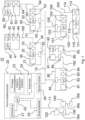
- FIG. 1 an exemplary communication system 10 is shown, which can be used, for example, in telecontrol or station control technology.
- the exemplary communication system preferably has a primary communication device 20, which can be operated, for example, as a communication master.
- the primary communication device 20 can function as a control device, for example as a programmable logic controller.
- the exemplary primary communication device 20 has, among other things, a bus interface 26 which is designed to connect the primary communication device 20 to a data bus 70. It should be noted at this point that the data bus is preferably designed for bit-serial data transmission. The data bus can also be a peripheral bus.
- coupling modules can be connected to the data bus.
- the coupling modules 30, 50, 80 and 110 are connected to the data bus 70.
- the coupling modules 30, 50, 80 and 110 each have a bus interface 35, 55, 85 and 105, respectively.
- the bus interfaces 26, 35, 55, 85 and 105 can be designed, for example, according to the Modbus communication protocol, according to a communication protocol according to the IEC60870-5-101 standard or the IEC60870-5-103 standard.
- the primary communication device 20 can, for example, have a further bus interface 25, which is designed to connect the primary communication device to a further data bus 71.
- the bus interface 25 can also be designed, for example, according to the Modbus communication protocol, according to a communication protocol according to the IEC60870-5-101 standard or the IEC60870-5-103 standard.
- Further connection modules can be connected to the further data bus 71 in a similar manner to the data bus 70, with two connection couplings 120 and 140 being shown according to the exemplary communication system.
- the exemplary primary communication device 20 further preferably has a memory device 23 in which software for monitoring and controlling the primary communication device 20 is stored.
- the storage device can have several separate memories.
- the software includes a first program that implements a communication protocol that supports master/slave operation, and a second program that implements a star coupler functionality implemented.
- the software preferably also includes a firmware or an operating system.
- control unit 22 preferably causes the primary communication system 20 to carry out steps a) and b) while executing the first program.
- the control unit 22 causes the primary communication device 20 to carry out steps c) to e) while executing the second program.
- the first program when executed by the control unit 22, can cause the primary communication device to control, for example, a serial data transmission, the communication protocol being, for example, a Modbus protocol, a communication protocol according to the IEC60870-5-101 standard or according to the IEC60870 standard -5-103 can be used.
- the bus interface 26 and, if present, the bus interface 25 can be designed as a serial bus interface.
- control unit 22 can be designed to cause the primary communication device 20 to send at least some of the copied communication telegrams by executing the software stored in the primary communication device 20 and in particular by executing the first program to segment and send the segments of each segmented communication telegram individually via the bus interface 26 or, if available, via the bus interface 25.
- a further memory device 21 can be provided in the primary communication device 20, in which at least one application program is stored, which contains, for example, the function block of a communication master and/or instructions for controlling a special application.
- each coupling module has a bus interface for connecting to the data bus 70 or the data bus 71.
- the coupling modules can preferably be constructed and operated identically or similarly, the exemplary structure and one are presented below exemplary functionality of the coupling modules is explained primarily using the coupling module 30. The following explanations regarding the coupling module 30 therefore also apply to the coupling modules 50, 80, 100, 120 and 140.
- the coupling module 30 has an electro-optical converter device 33 with an optical transmitting and receiving device.
- the electro-optical converter device can have two separate electro-optical converters, namely one for emitting light signals and one for receiving light signals. In this way, full duplex data transmission is possible.
- the electro-optical converter device 33 can have a light-emitting component, for example an LED, which can function as a light transmitter in transmitting mode and as a photodiode in receiving mode.
- the coupling module 30 has a single optical fiber connection device 34 connected to the electro-optical converter device 33, which has a single connection for connecting a single optical fiber 160 or two connections, depending on whether a full duplex operation or a half duplex communication operation is implemented each of which can be connected to an optical fiber for receiving and a second optical fiber for sending light signals.
- the electro-optical converter device 33 has a single light-emitting component for sending and receiving light signals. It should be noted at this point that the functioning of electro-optical converter devices is known per se.
- the electro-optical converter device 33 in transmission mode, converts electrical signals, which represent a communication telegram, into light signals that are emitted via the optical fiber connection device 34, while in reception mode it converts the light signals arriving at the optical fiber connection device 34 into electrical signals in turn represent a communication telegram, converted and fed to the bus interface 35.
- a single secondary communication device 40 can be connected to the single optical fiber connection device 34 of the coupling module 30 by means of at least one optical fiber 160.
- the coupling module 30 can have a memory device 31 in which software is stored.
- the coupling module 30 preferably has a control and evaluation device 32, which is designed to cause the coupling module 30 to receive information from an electrical communication telegram arriving at the bus interface 35, which has a first address, by executing the software stored in the memory device 31 is assigned to a secondary communication device, and contains a second address, which is assigned to a coupling module, to read out the second address and to supply the communication telegram via the electro-optical converter device 33 to the single optical fiber connection device 34 only if the read second address corresponds to that of the coupling module 30 assigned unique address matches.
- the unique address of the coupling module 30 can also be stored in the memory device 31.
- the control and evaluation device 32 of the coupling module 30 is advantageously designed to cause the coupling module 30 to remove the second address from the communication telegram and to supply the thus processed communication telegram to the electro-optical converter device 33 by executing the software stored in the memory device 31.
- the control and evaluation device 32 can be a microcontroller or a microprocessor.
- the control and evaluation device 32 can also be designed, by executing the software stored in the memory device 31, to cause the coupling module 30 to receive a light signal arriving at the single optical fiber connection device 34, which represents a communication telegram which has an address that corresponds to the secondary Communication device 40 is clearly assigned, contains, via the electro-optical converter device 33 as an electrical signal to the bus interface 35 for transmission via the data bus 70. Furthermore, the control and evaluation device 32 of the coupling module 30 can be designed to cause the coupling module 30 to process the segments arriving at the bus interface 35 by executing the software stored in the memory device 31 segmented communication telegram to be reassembled into the original communication telegram.
- the remaining coupling modules 50, 80, 100, 120 and 140 also have a control and evaluation unit 52, 82 or 102, a memory device 51, 81 or 101 for storing software, an electro-optical converter device 53, 83 or 103 and a single optical fiber connection device 54, 84 or 104.
- a control and evaluation unit 52, 82 or 102 for storing software
- a memory device 51, 81 or 101 for storing software for storing software
- an electro-optical converter device 53, 83 or 103 and a single optical fiber connection device 54, 84 or 104.
- the corresponding components in the connection couplings 120 and 140 are not shown.
- each optical fiber connection device and thus also the optical fiber connection device 54, 84 and 104 and the corresponding optical fiber connection devices of the coupling modules 120 and 140, each have only one connection for connecting an optical fiber 161, 162, 163, 164 or 165 , which is used for both transmitting and receiving operations.
- a secondary communication device 60 is connected to the single optical fiber connection device 54 of the coupling module 50 via the optical fiber 161, to the only optical fiber connection device 84 of the coupling module 80 there is a secondary communication device 90 via the optical fiber 162, to the single optical fiber connection device 104 secondary communication device 110 via the optical fiber 163, a secondary communication device 130 is connected to the only optical fiber connection device of the coupling module 120 via the optical fiber 164 and a secondary communication device 150 is connected to the only optical fiber connection device of the coupling module 140 via the optical fiber 165.
- the secondary communication devices 60, 90 and 110 can each have a memory device 61, 91 or 111, a control unit 62, 92 or 112, an electro-optical converter device 63, 93 or 113 and an optical fiber connection device 64, 94 or 114.
- the secondary communication devices 130 and 150 may preferably include the same components (not shown).
- Each of the secondary communication devices 40, 60, 90, 110, 130 and 150 is preferably assigned a unique address and, depending on the implementation, for example a broadcast address, which can be stored in the respective storage device.
- the control and evaluation device 42 of the secondary communication device 40 can be designed to, by executing the software stored in the storage device 41, cause the secondary communication device 40 to use the first communication telegram received via the optical fiber connection device 44, which contains a first address Read out the address and check whether it matches the unique address assigned to the secondary communication device 40 and, if there is a match, generate a response telegram depending on the received communication telegram and feed it to the optical fiber connection device 44 via the electro-optical converter device 43 for sending. It goes without saying that the light signals received at the optical fiber connection device 44, which represent the communication telegram, are first converted into an electrical signal by means of the electro-optical converter device 43, which is then fed to the control and evaluation device 42 for further processing. It should be noted that the structure and functionality of the remaining secondary communication devices can be identical or at least similar to the functionality and structure of the secondary communication device 40. Therefore, the explanations regarding the secondary communication device 40 also apply to the secondary communication devices 60, 90, 110, 130 and 150.
- the optional bus interface 25 of the primary communication device 20 is deactivated or not present at all.
- a communication infrastructure is assumed according to which the primary communication device 20, the coupling modules 30, 50, 80 and 100 and the secondary communication devices 40, 60, 90 and 110 form a communication group.
- the secondary communication devices 40, 60, 90 and 110 are temperature sensors and that, according to an exemplary application, the primary communication device 20, which acts as a communication master, queries temperature values from the secondary communication devices 40, 60, 90 and 110 should.
- the primary communication device 20 starts, for example, the application program stored in the storage device 21 and, executing the first program stored in the storage device 23, generates a communication telegram for a predetermined secondary communication device, in this case initially for the secondary communication device 40.
- the control unit 22 inserts the primary communication device 20 into the communication telegram as the first address, the address clearly assigned to the secondary communication device 40.
- a command is inserted into the communication telegram, which requests a secondary communication device to transmit its current temperature data.
- the primary communication device 20 or the second program is aware of the configuration of the communication infrastructure of the communication system 10, that is, it knows the unique addresses of the coupling modules 30, 50, 80 and 100 and the parameter n, which corresponds to the number of coupling modules of the communication group.
- the parameter n is 4 in the present case. Consequently, the control unit 22, preferably by executing the second program which implements the star coupler functionality, causes the primary communication device 20 to copy the generated communication telegram with the address of the secondary communication device 40 four times and into each of them To insert a second address into four copied communication telegrams, the second addresses being different and each being assigned to one of the coupling modules 30, 50, 80 and 100.
- the unique address of the coupling module 30 is included in the first copied communication telegram the second copied communication telegram contains the unique address of the coupling module 50, the third copied communication telegram contains the unique address of the coupling module 80 and the fourth copied communication telegram contains the unique address of the coupling module 100.
- the control unit 22 preferably while executing the second program, causes the primary communication device 20 to transmit all four copied communication telegrams one after the other via the bus interface 26 and via the bus 70.
- the four copied communication telegrams transmitted as electrical signals via the bus 70 are received at the bus interfaces 35, 55, 85 and 105 of the coupling modules 30, 50, 80 and 100, respectively.
- each of the coupling modules 30, 50, 80 and 100 causes the respective coupling module, by executing the stored software, to obtain the second address from each of the four copied communication telegrams that arrive at the respective bus interface, which represents a unique address of a coupling module , read out and compared with the unique address stored in the respective coupling module. Only the copied communication telegram is then fed via the electro-optical converter device to the single optical fiber connection device, the read second address of which matches the unique address assigned to the respective coupling module.
- the communication telegram generated by the primary communication device 20 and intended for the secondary communication device 40 is transmitted in copied form to all secondary communication devices 40, 60, 90 and 110 via the respective optical fibers.
- the received communication telegram is only accepted by the secondary communication device 40 and rejected by all other secondary communication devices. This is because the unique address of the secondary communication device 40 is contained as the first address in every communication telegram received.
- the first copied communication telegram, received as a light signal is first converted into a corresponding electrical communication telegram via the electro-optical converter device 43.
- the control and evaluation device 42 by executing the software stored in the storage device 41, causes the secondary communication device 40 to read out the first address from the received communication telegram and to compare it for correspondence with the unique address of the secondary communication device stored in the storage device 41. Only the control and evaluation device 42 determines a match between the first address contained in the communication telegram and the address clearly assigned to the secondary communication device 40.
- the control and evaluation device 42 of the secondary communication device 40 in response to the command contained in the communication telegram, generates a response telegram in which the current temperature and the unique address of the secondary communication device 40 is stored, and this response telegram via the electro-optical converter device 43 to the optical waveguide connection device 44 as a light signal and to transmit it via the optical waveguide 160 to the coupling module 30.
- the coupling module 30 receives the optical response telegram at the optical fiber connection device 34, which is converted into a corresponding electrical response telegram by means of the electro-optical converter device 33 and transmitted to the primary communication device 20 via the bus interface 35 and the data bus 70.
- the control unit 22 of the primary communication device 20 is designed, for example, to process the received response telegram by executing the software stored in the primary communication device 20, which is preferably the second program, and to send the current temperature values contained therein to the application program stored in the storage device 21 for further information to be handed over for use.
- three further communication telegrams are generated by the primary communication device 20 in the manner described above, each of which contains a different one of the unique addresses of the secondary communication devices 60, 90 and 110 is inserted.
- Each of the three communication telegrams is then copied four times and transmitted one after the other via the bus interface 26 and the bus 70 to the coupling modules 30, 50, 80 and 100. The procedure explained in detail above is then repeated for each of the copied communication telegrams.
- the primary communication device 20 has received the current temperature values of each of the secondary communication devices 40, 60, 90 and 110.
- the optional bus interface 25 of the primary communication device 20 is deactivated or not present at all.
- a communication infrastructure is assumed, according to which the primary communication device 20, the coupling modules 30, 50 and the secondary communication devices 40, 60 form a first communication group, while the primary communication device 20, the coupling modules 80, 100 and the secondary communication devices 90 , 110 form a second communication group.
- the secondary communication devices 40, 60, 90 and 110 are temperature sensors and that, according to an exemplary application, the primary communication device 20, which acts as a communication master, queries temperature values from the secondary communication devices 40, 60, 90 and 110 should.
- the primary communication device 20 or the second program knows the configuration of the communication infrastructure of the communication system 10, that is, it knows the first communication group and thus the unique addresses of the coupling modules 30 and 50, and the parameter n, which is the number of Coupling modules correspond to the first communication group, as well as the second communication group and thus the unique addresses of the coupling modules 80 and 100, and the parameter m, which corresponds to the number of coupling modules of the second communication group.
- the parameters n and m are each 2 in this case.
- the primary communication device 20 now starts the communication of the first communication group.
- the primary communication device 20 accesses, for example, the application program stored in the storage device 21 and, by executing the first program stored in the storage device 23, generates a communication telegram for a predetermined secondary communication device, in this case initially for the secondary communication device 40 of the first communication group.
- the control unit 22 causes the primary communication device 20 to insert the address clearly assigned to the secondary communication device 40 into the communication telegram as the first address. Furthermore, a command is inserted into the communication telegram, which requests a secondary communication device to transmit its current temperature data.
- control unit 22 preferably executing the second program that implements the star coupler functionality, causes the primary communication device 20 to copy the generated communication telegram with the address of the secondary communication device 40 twice and to insert a second address into each of the four copied communication telegrams , whereby the second addresses are different and are each assigned to one of the coupling modules 30 and 50.
- the unique address of the coupling module 30 is inserted into the first copied communication telegram and the unique address of the coupling module 50 is inserted into the second copied communication telegram.
- the control unit 22, preferably while executing the second program causes the primary communication device 20 to transmit the two copied communication telegrams one after the other via the bus interface 26 and via the bus 70.
- the two copied communication telegrams are each received at the bus interfaces 35 and 55 of the coupling modules 30 and 50.
- the control and evaluation device of each of the coupling modules 30 and 50 causes the respective coupling module, by executing the stored software, to read out the second address, which represents a unique address of a coupling module, from each of the two copied communication telegrams that arrive at the respective bus interface to compare the unique address stored in the respective coupling module. Only the copied communication telegram is then fed via the electro-optical converter device to the single optical fiber connection device, the read second address of which matches the unique address assigned to the respective coupling module.
- the communication telegram generated by the primary communication device 20 and intended for the secondary communication device 40 is transmitted in copied form to the two secondary communication devices 40 and 60 via the respective optical fibers.
- the received communication telegram is only accepted by the secondary communication device 40 and rejected by the secondary communication device 60. This is because the unique address of the secondary communication device 40 is contained as the first address in every communication telegram received.
- the first copied communication telegram, received as a light signal is first converted into a corresponding electrical communication telegram via the electro-optical converter device 43.
- the control and evaluation device 42 by executing the software stored in the storage device 41, causes the secondary communication device 40 to read out the first address from the received communication telegram and to compare it for correspondence with the unique address of the secondary communication device stored in the storage device 41. Only the control and evaluation device 42 determines a match between the first address contained in the communication telegram and the address clearly assigned to the secondary communication device 40.
- control and evaluation device 42 causes the secondary communication device 40, in response to the command contained in the communication telegram, to generate a response telegram in which the current temperature and the unique address of the secondary communication device 40 is stored, and this response telegram via the electro-optical To supply the converter device 43 to the optical waveguide connection device 44 as a light signal and to transmit it to the coupling module 30 via the optical waveguide 160.
- the coupling module 30 receives the optical response telegram at the optical fiber connection device 34, which is converted into a corresponding electrical response telegram by means of the electro-optical converter device 33 and transmitted to the primary communication device 20 via the bus interface 35 and the data bus 70.
- the control unit 22 of the primary communication device 20 is designed, for example, to process the received response telegram by executing the software stored in the primary communication device 20, which is preferably the second program, and to send the current temperature values contained therein to the application program stored in the storage device 21 for further information to be handed over for use.
- a further communication telegram is generated, for example in the manner described above, by the primary communication device 20, into which the unique address of the secondary communication device 60 is inserted.
- the further communication telegram is then copied twice.
- the copied communication telegrams are then transmitted one after the other via the bus interface 26 and the bus 70 to the coupling modules 30 and 50.
- the primary communication device 20 has the current temperature values of the two secondary communication devices 40 and 60 of the first communication group.
- the primary communication device 20 now starts the communication of the second communication group in order to obtain the current temperature values of the two secondary communication devices 90 and 110 of the second communication group. Since this communication essentially corresponds to the communication of the first communication group, in order to avoid repetitions, reference is made to the above detailed description of the functioning of the communication system 10 with regard to the first communication group.
- a third exemplary scenario is described below, according to which the bus interface 25 is also present or activated. It is now assumed that the primary communication device 20, the coupling modules 30, 50, 80 and 100 and the secondary communication devices 40, 60, 90 and 110 are a first Form a communication group, while the primary communication device 20, the coupling modules 120 and 140 connected to the second data bus 71 and the secondary communication devices 130 and 150 form a second communication group. For example, the two secondary communication devices 130 and 150 are also temperature sensors.
- the primary communication device 20 is configured or programmed in such a way that all communication telegrams or copied communication telegrams that contain the unique address of the coupling module 120 or the coupling module 140 are transmitted via the bus interface 25 and the data bus 71, while all communication telegrams or copied ones Communication telegrams, which contain the unique address of the coupling modules 30, 50, 80 or 100, are transmitted via the bus interface 26 and the data bus 70.
- This can be achieved, for example, by assigning a unique identifier to the two bus interfaces 25, 26, which is inserted into the respective copied communication telegrams, for example by the second program.
- the functionality of the communication system 10 with regard to the first communication group essentially corresponds to that of the first scenario, with the difference that the primary communication device 20 is also designed to receive all copied communication telegrams that contain the unique address of one of the Coupling modules 30, 50, 80 and 100 are transmitted via the bus interface 26 and all response telegrams that contain the unique address of one of the secondary communication devices 40, 60, 90, 110 are assigned to the first communication group.
- scenario 1 As a result, at the end of the communication cycle, the primary communication device 20 will have received the current temperature values from the secondary communication devices 40, 60, 90 and 110.
- the functionality of the communication system 10 with regard to the second communication group essentially corresponds to the functionality that was described in the second scenario with regard to the first or second communication group, with the difference that the primary communication device 20 is further designed to receive all copied communication telegrams that have the unique Address of one of the two coupling modules 120 and 140 is transmitted via the bus interface 25, and all response telegrams that contain the unique address of one of the two secondary communication devices 130 and 150 are assigned to the second communication group.
- scenario 2 As a result, at the end of the communication cycle, the primary communication device 20 will have received the current temperature values from the secondary communication devices 130 and 150.
- the second program which implements the star coupler functionality, can be implemented as part of a firmware, which can also be stored in the memory device 23, or as a separate application program, which can be stored, for example, in the memory device 21.
Landscapes
- Engineering & Computer Science (AREA)
- Physics & Mathematics (AREA)
- Theoretical Computer Science (AREA)
- General Physics & Mathematics (AREA)
- General Engineering & Computer Science (AREA)
- Computer Networks & Wireless Communication (AREA)
- Signal Processing (AREA)
- Optics & Photonics (AREA)
- Optical Communication System (AREA)
- Small-Scale Networks (AREA)
Abstract
Description
- Die Erfindung betrifft ein primäres Kommunikationsgerät, insbesondere einen Kommunikationsmaster, ein Ankopplungsmodul für ein sekundäres Kommunikationsgerät, insbesondere ein Kommunikationsslave, sowie ein Kommunikationssystem, das ein primäres Kommunikationsgerät, mehrere Ankopplungsmodule und mehrere sekundäres Kommunikationsgeräte aufweist.
- Zur Übertragung von Daten zwischen einem Zentralgerät und unterlagerten Geräten kann ein Datenbus in Form einer Kupferleitung verwendet werden, an die das Zentralgerät und die unterlagerten Geräte angeschlossen werden können. Die Datenübertragung kann beispielsweise durch ein Kommunikationsprotokoll nach dem Standard IEC 60870-5-103 oder IEC 60870-5-101 gesteuert werden. Hierbei sendet das Zentralgerät, welches als Kommunikationsmaster ausgebildet sein kann, ein Telekommunikationstelegramm an alle unterlagerten Geräte, wobei nur das adressierte unterlagerte Gerät das empfangene Kommunikationstelegramm weiterverarbeiten kann. Wird als Kommunikationsnetz ein Glasfasernetz verwendet, so muss vom Zentralgerät zu jedem einzelnen unterlagerten Gerät eine Punkt-zu-Punkt-Verbindung implementiert werden. Hierfür kann ein Lichtwellenleiter-Sternkoppler eingesetzt werden, der ein Lichtsignal in mehrere Lichtwellenleiter gleichzeitig einkoppelt.
- Derartige Lichtwellenleiter-Sternkoppler sind bekannt und beispielsweise im Internet, zu finden unter der URL https://de.wikipedia.org/wiki/sternkoppler, beschrieben. Derartige Sternkoppler sind als hardwarebasierte Netzwerkkomponenten ausgebildet und werden verwendet, um zum Beispiel ein Kommunikationstelegramm in Form von Lichtsignalen in mehrere Lichtwellenleiter gleichzeitig einzukoppeln. Ein solcher Sternkoppler weist eine festgelegte Anzahl an Ports zum Anschließen von Glasfasern auf.
- Aus der
DE 41 06 726 B4 ist ein passiver NxN-Sternkoppler vom Reflexionstyp bekannt, der in einem Kommunikationsnetzwerk für Kraftfahrzeuge verwenden wird. Der Erfindung liegt die Aufgabe zugrunde, ein primäres Kommunikationsgerät, ein Ankopplungsmodul und ein Kommunikationssystem zu schaffen, die in kostengünstiger Weise eine Kommunikation zwischen einem primären Kommunikationsgerät und mehreren sekundären Kommunikationsgeräten, die mittels Lichtwellenleitern an das Kommunikationssystem angeschlossen sind, zu ermöglichen, und zwar ohne einen hardwarebasierten und in der Anzahl an Ports festgelegten Lichtwellenleiter-Sternkoppler verwenden zu müssen. Gemäß einem vorteilhaften Aspekt kann hierdurch ein Kommunikationssystem kostengünstig und schnell skaliert werden. - Ein Kerngedanke der Erfindung kann darin gesehen werden, ein Kommunikationssystem zu schaffen, welches eine Kommunikation zwischen einem primären Kommunikationsgerät und mehreren sekundären Kommunikationsgeräten insbesondere nach einem Master/Slave-Betrieb ermöglicht, wobei die sekundären Kommunikationsgeräte jeweils über wenigstens einen Lichtwellenleiter an das Kommunikationssystem angebunden sind. Anstatt einen hardwarebasierten Sternkoppler einzusetzen, ist in dem primären Kommunikationsgerät eine softwarebasierte Sternkoppler-Funktionalität implementiert, die die Aufgaben eines als Hardwarebauteil ausgebildeten Sternkopplers übernimmt.
- Das oben genannte technische Problem wird durch die Merkmale des Anspruchs 1 gelöst. Vorteilhafte Ausgestaltungen und Weiterbildungen sind Gegenstand der Ansprüche 2 bis 6.
- Demnach ist ein primäres Kommunikationsgerät vorgesehen, welches folgende Merkmale aufweisen kann:
- Eine Busschnittstelle, die zum Anschließen des primären Kommunikationsgeräts an einen Datenbus ausgebildet ist,
- eine Speichereinrichtung, in der eine Software gespeichert ist, und
- eine Steuereinheit, die dazu ausgebildet ist, unter Ausführung der Software das primäre Kommunikationsgerät zu veranlassen,
- ein Kommunikationstelegramm für ein vorbestimmtes sekundäres Kommunikationsgerät bereitzustellen,
- in das Kommunikationstelegramm eine erste Adresse, die dem vorbestimmten sekundären Kommunikationsgerät zugeordnet ist, einzufügen,
- das Kommunikationstelegramm n-mal zu kopieren, wobei n größer als 1 ist,
- in jedes der kopierten Kommunikationstelegramme, eine zweite Adresse einzufügen, wobei die zweiten Adressen unterschiedlich sind und jeweils einem separaten Ankopplungsmodul zugeordnet sind, und
- jedes der kopierten Kommunikationstelegramme über die Busschnittstelle zu versenden.
- Angemerkt sei, dass die erste Adresse eine Broadcast-Adresse oder eine dem vorbestimmten sekundären Kommunikationsgerät eindeutig zugeordnete Adresse sein kann. Mithilfe einer Broadcast-Adresse kann das primäre Kommunikationsgerät ein einziges Kommunikationstelegramm an alle sekundären Kommunikationsgeräte schicken, um beispielsweise die Uhrzeit zu synchronisieren.
- Gemäß einer vorteilhaften Ausgestaltung fungiert das primäre Kommunikationsgerät als ein Master-Kommunikationsgerät und die sekundären Kommunikationsgeräte als Slave-Kommunikationsgeräte.
- Gemäß einer vorteilhaften Ausgestaltung enthält die in der Speichereinrichtung gespeicherte Software ein erstes Programm, das ein Kommunikationsprotokoll, welches einen Master/Slave-Betrieb unterstützt, implementiert, und ein zweites Programm, dass eine Sternkoppler-Funktionalität implementiert. Unter einem Master/Slave-Betrieb ist insbesondere ein Aufrufbetrieb zu verstehen, bei dem das primäre Kommunikationsgerät gezielt sekundäre Kommunikationsgeräte auffordert, Daten, zum Beispiel aktuelle Messwerte, zum primären Kommunikationsgerät zu übertragen.
- Das zweite, eine Sternkoppler-Funktionalität ausführende Programm, kennt im Unterschied zum Kommunikationsprotokoll die implementierte Kommunikationsinfrastruktur. Deshalb veranlasst das zweite Programm, wenn es von der Steuereinheit ausgeführt wird, das primäre Kommunikationsgerät das Kommunikationstelegramm n-mal zu kopieren, wobei n größer als 1 ist, in jedes der kopierten Kommunikationstelegramme, eine zweite Adresse einzufügen, wobei die zweiten Adressen unterschiedlich sind und jeweils einem separaten Ankopplungsmodul zugeordnet sind, und jedes der kopierten Kommunikationstelegramme über die Busschnittstelle zu versenden. Der Parameter n entspricht vorzugsweise der Anzahl an sekundären Kommunikationsgeräten, mit denen das primäre Kommunikationsgerät eine Kommunikationsgruppe bildet.
- Das erste Programm kann vorzugsweise ein Kommunikationsprotokoll zur seriellen Datenübertragung implementieren. Vorzugsweise handelt es sich bei dem Kommunikationsprotokoll beispielsweise um ein Modbus-Protokoll, ein Kommunikationsprotokoll gemäß dem Standard IEC60870-5-103 oder gemäß dem Standard IEC60870-5-101. Die Busschnittstelle kann als serielle Busschnittstelle ausgebildet sein.
- Vorzugsweise fungiert das primäre Kommunikationsgerät als ein Steuergerät. Es kann insbesondere zum Einsatz in der Fernwirk- oder Stationsleittechnik ausgebildet sein.
- Um die Flexibilität und Skalierbarkeit des primären Kommunikationsgerät zu erhöhen, kann eine weitere Busschnittstelle vorgesehen sein, die zum Anschließen des primären Kommunikationsgeräts an einen weiteren Datenbus ausgebildet ist. Die Steuereinheit kann vorzugsweise dazu ausgebildet sein, unter Ausführung der im primären Kommunikationsgerät gespeicherten Software das primäre Kommunikationsgerät zu veranlassen, jedes der kopierten Kommunikationstelegramme über die Busschnittstelle oder die weitere Busschnittstelle zu versenden. Vorzugsweise kann hierzu in jedes kopierte Kommunikationstelegramm eine Kennung der Busschnittstelle oder der weiteren Busschnittstelle eingefügt werden.
- Um eine flexible Datenübertragung, die vorzugsweise von der Übertragungsgeschwindigkeit entkoppelt ist, zu ermöglichen, kann die Steuereinheit des primären Kommunikationsgeräts dazu ausgebildet sein, unter Ausführung der Software das primäre Kommunikationsgerät zu veranlassen, zumindest einige der kopierten Kommunikationstelegramme zu segmentieren und die Segmente jedes segmentierten Kommunikationstelegramms einzeln über die Busschnittstelle zu versenden.
- Das oben genannte technische Problem wird ferner durch die Merkmale des Anspruchs 7 gelöst. Vorteilhafte Ausgestaltungen und Weiterbildungen sind Gegenstand der Ansprüche 8 bis 11.
- Demnach ist ein Ankopplungsmodul vorgesehen, welches folgende Merkmale aufweisen kann:
- Eine Busschnittstelle, die zum Anschließen des Ankopplungsmoduls an einen Datenbus ausgebildet ist, wobei dem Ankopplungsmodul eine eindeutige Adresse zugeordnet ist, eine elektrooptische Wandlereinrichtung mit einer optischen Sende- und Empfangseinrichtung,
- eine einzige Lichtwellenleiter-Anschlusseinrichtung, die zum Anschließen eines einzigen sekundären Kommunikationsgeräts mittels wenigstens eines Lichtwellenleiters ausgebildet ist,
- eine Speichereinrichtung, in der eine Software gespeichert ist, und
- eine Steuer- und Auswerteeinrichtung, die dazu ausgebildet ist, unter Ausführung der im Ankopplungsmodul gespeicherten Software das Ankopplungsmodul zu veranlassen, aus einem an der Busschnittstelle ankommenden Kommunikationstelegramm, welches eine erste Adresse, die einem sekundären Kommunikationsgerät zugeordnet ist, und eine zweite Adresse, die einem Ankopplungsmodul zugeordnet ist, enthält, die zweite Adresse auszulesen und das Kommunikationstelegramm nur dann über die elektrooptische Wandlereinrichtung der einzigen Lichtwellenleiter-Anschlusseinrichtung zu zuführen, wenn die ausgelesene zweite Adresse mit der dem Ankopplungsmodul zugeordneten eindeutigen Adresse übereinstimmt.
- Gemäß einem vorteilhaften Ausführungsbeispiel kann die elektrooptische Wandlereinrichtung eine Licht-emittierende Einrichtung aufweisen, die nicht nur als Lichtsender, sondern im Empfangsfall auch als Empfänger-Fotodiode eingesetzt werden kann. In diesen Fall weist die Lichtwellenleiter-Anschlusseinrichtung lediglich einen Anschluss zum Anschließen eines einzigen Lichtwellenleiters auf, der sowohl im Sende- als auch im Empfangsbetrieb verwendet werden kann. Dies ist insbesondere dann möglich, wenn das Ankopplungsmodul im Halbduplex-Betrieb arbeiten soll.
- Soll ein Vollduplex-Kommunikationsbetrieb gewährleistet werden, so weist die elektrooptische Wandlereinrichtung zwei getrennte elektrooptische Wandler auf, nämlich eine für den optischen Sendebetrieb und eine für den optischen Empfangsbetrieb. In diesem Fall weist die einzige Lichtwellenleiter-Anschlusseinrichtung zwei separate Anschlüsse auf, an die jeweils ein Lichtwellenleiter für den Sendebetrieb und ein Lichtwellenleiter für den Empfangsbetrieb angeschlossen werden kann.
- Gemäß einer vorteilhaften Ausgestaltung kann die Steuer- und Auswerteeinrichtung des Ankopplungsmoduls dazu ausgebildet sein, unter Ausführung der im Ankopplungsmodul gespeicherten Software das Ankopplungsmodul zu veranlassen, die zweite Adresse aus dem Kommunikationstelegramm zu entfernen und nur das entsprechend bearbeitete Kommunikationstelegramm über die einzige Lichtwellenleiter-Anschlusseinrichtung auszusenden.
- Die Busschnittstelle des Ankopplungsmoduls kann als serielle Busschnittstelle ausgebildet sein.
- Gemäß einer vorteilhaften Weiterbildung kann die Steuer- und Auswerteeinrichtung des Ankopplungsmoduls ferner dazu ausgebildet sein, unter Ausführung der im Ankopplungsmodul gespeicherten Software das Ankopplungsmodul zu veranlassen, ein an der einzigen Lichtwellenleiter-Anschlusseinrichtung ankommendes Kommunikationstelegramm, welches eine Adresse, die einem sekundären Kommunikationsgerät eindeutig zugeordnet ist, enthält, mittels der elektrooptischen Wandlereinrichtung über die Busschnittstelle zu versenden.
- Gemäß einer vorteilhaften Ausgestaltung kann die Steuer- und Auswerteeinrichtung des Ankopplungsmoduls dazu ausgebildet sein, unter Ausführung der im Ankopplungsmodul gespeicherten Software das Ankopplungsmodul zu veranlassen, die an der Busschnittstelle ankommenden Segmente eines segmentierten Kommunikationstelegramms wieder zu dem ursprünglichen Kommunikationstelegramm zusammenzufügen.
- Das oben genannte technische Problem wird ebenfalls durch die Merkmale des Anspruchs 12 gelöst. Vorteilhafte Ausgestaltungen und Weiterbildungen sind Gegenstand der Ansprüche 13 bis 16.
- Das Kommunikationssystem ist insbesondere zum Einsatz in der Fernwirk- oder Stationsleittechnik geeignet.
- Das Kommunikationssystem kann folgende Merkmale aufweisen: Einen Datenbus,
- ein primäres Kommunikationsgerät nach einem der Ansprüche 1 bis 6, das an dem Datenbus angeschlossen ist,
- mehrere erste Ankopplungsmodule nach einem der Ansprüche 7 bis 11, die jeweils an dem Datenbus angeschlossen sind, wobei jedem der ersten Ankopplungsmodule eine eindeutige Adresse zugeordnet ist.
- An die einzige Lichtwellenleiter-Anschlusseinrichtung jedes der Ankopplungsmodule ist ein erstes sekundäres Kommunikationsgerät über wenigstens einen Lichtwellenleiter angeschlossen, wobei jedem der ersten sekundären Kommunikationsgeräte eine eindeutige Adresse zugeordnet ist, wobei n, d. h. die Anzahl der Kopiervorgänge, gleich der Anzahl der ersten Ankopplungsmodule ist. Angemerkt sei, dass n als einstellbarer bzw. programmierbarer Parameter in dem primären Kommunikationsgerät gespeichert werden kann.
- Jedes der ersten sekundären Kommunikationsgeräte weist eine Speichereinrichtung, in der eine Software gespeichert ist, eine Lichtwellenleiter-Anschlusseinrichtung, eine elektrooptische Wandlereinrichtung mit einer optischen Sende- und Empfangseinrichtung und eine Steuer- und Auswerteeinrichtung auf. Die Steuer-und Auswerteeinrichtung jedes der ersten sekundären Kommunikationsgeräte ist dazu ausgebildet, unter Ausführung der im ersten sekundären Kommunikationsgerät gespeicherten Software das erste sekundäre Kommunikationsgerät zu veranlassen,
- aus einem über die Lichtwellenleiter-Anschlusseinrichtung empfangenen Kommunikationstelegramm, welches eine erste Adresse enthält, die erste Adresse auszulesen und auf Übereinstimmung mit der dem jeweiligen ersten sekundären Kommunikationsgerät zugeordneten eindeutigen Adresse zu prüfen, und
- bei Übereinstimmung in Abhängigkeit von dem empfangenen Kommunikationstelegramm ein Antworttelegramm zu erzeugen und dieses über die elektrooptische Wandlereinrichtung der Lichtwellenleiter-Anschlusseinrichtung zum Versenden zuzuführen.
- Der Datenbus ist vorzugsweise als serieller Bus ausgebildet. Der Datenbus kann beispielsweise auch ein Peripheriebus sein. In diesem Fall können das primäre Kommunikationsgerät und die Ankopplungsmodule vorzugsweise in einem gemeinsamen Gehäuse untergebracht sein.
- Gemäß einer vorteilhaften Weiterbildung kann das primäre Kommunikationsgerät dazu ausgebildet sein, an seiner Busschnittstelle ein Antworttelegramm von einem der ersten sekundären Kommunikationsgeräte zu empfangen, wobei die Steuereinheit des primären Kommunikationsgeräts dazu ausgebildet sein kann, unter Ausführung der im primären Kommunikationsgerät gespeicherten Software das empfangene Antworttelegramm auszuwerten und/oder weiterzuleiten und/oder zu verarbeiten.
- Um die Flexibilität und Einsatzmöglichkeiten des Kommunikationssystems zu erhöhen, können mehrere zweite Ankopplungsmodule nach einem der Ansprüche 7 bis 11 vorgesehen sein, die jeweils an dem Datenbus angeschlossen sind. Jedem der zweiten Ankopplungsmodule ist wiederum eine eindeutige Adresse zugeordnet, wobei an die einzige Lichtwellenleiter-Anschlusseinrichtung jedes der zweiten Ankopplungsmodule ein zweites sekundäres Kommunikationsgerät über wenigstens einen Lichtwellenleiter angeschlossen ist, wobei jedem der zweiten sekundären Kommunikationsgeräte eine eindeutige Adresse zugeordnet ist. Das primäre Kommunikationsgerät und die ersten Ankopplungsmodule können als eine erste Kommunikationsgruppe betrachtet werden, wohingegen das primäre Kommunikationsgerät und die zweiten Ankopplungsmodule als eine zweite Kommunikationsgruppe betrachtet werden können. Die Steuereinheit des primären Kommunikationsgeräts ist vorzugsweise ferner dazu ausgebildet, unter Ausführung der im primären Kommunikationsgerät gespeicherten Software das primäre Kommunikationsgerät zu veranlassen,
- ein zweites Kommunikationstelegramm für ein vorbestimmtes zweites sekundäres Kommunikationsgerät bereitzustellen,
- in das zweite Kommunikationstelegramm eine erste Adresse, die dem vorbestimmten zweiten sekundären Kommunikationsgerät zugeordnet ist, einzufügen,
- das zweite Kommunikationstelegramm m-mal zu kopieren wobei m größer als 1 und gleich der Anzahl der zweiten Ankopplungsmodule ist,
- in jedes der kopierten Kommunikationstelegramme eine zweite Adresse einzufügen, wobei die zweiten Adressen unterschiedlich sind und jeweils einem der zweiten Ankopplungsmodule zugeordnet sind, und
- jedes der kopierten Kommunikationstelegramme über die Busschnittstelle zu versenden.
- Um die Flexibilität und Einsatzmöglichkeiten noch weiter zu steigern, kann ein weiterer Datenbus vorgesehen sein, an dem das primäre Kommunikationsgerät und mehrere dritte Ankopplungsmodule nach einem der Ansprüche 7 bis 11 angeschlossen sind. Jedem der dritten Ankopplungsmodule ist eine eindeutige Adresse zugeordnet, wobei an die einzige Lichtwellenleiter-Anschlusseinrichtung jedes der dritten Ankopplungsmodule ein drittes sekundäres Kommunikationsgerät über wenigstens einen Lichtwellenleiter angeschlossen ist. Jedem der dritten sekundären Kommunikationsgeräte ist eine eindeutige Adresse zugeordnet.
- Die Erfindung wird nachfolgend in Verbindung mit der einzigen
Figur 1 näher erläutert. - In
Figur 1 ist ein beispielhaftes Kommunikationssystem 10 dargestellt, welches beispielsweise in der Fernwirk- oder Stationsleittechnik eingesetzt werden kann. - Das beispielhafte Kommunikationssystem weist vorzugsweise ein primäres Kommunikationsgerät 20 auf, welche beispielsweise als Kommunikations-Master betrieben werden kann. Das primäre Kommunikationsgerät 20 kann als Steuergerät, beispielsweise als speicherprogrammierbare Steuerung fungieren.
- Das beispielhafte primäre Kommunikationsgerät 20 weist unter anderem eine Busschnittstelle 26 auf, die zum Anschließen des primären Kommunikationsgerätes 20 an einen Datenbus 70 ausgebildet ist. Bereits an dieser Stelle sei angemerkt, dass der Datenbus vorzugsweise zur Bit-seriellen Datenübertragung ausgebildet ist. Der Datenbus kann auch ein Peripheriebus sein.
- An den Datenbus können mehrere Ankopplungsmodule angeschlossen werden. Gemäß dem beispielhaften Kommunikationssystem 10 sind an dem Datenbus 70 beispielsweise vier Ankopplungsmodule 30, 50, 80 und 110 angeschlossen. Hierzu weisen die Ankopplungsmodule 30, 50, 80 und 110 jeweils eine Busschnittstelle 35, 55, 85 bzw. 105 auf. Bereits an dieser Stelle sei erwähnt, dass die Busschnittstellen 26, 35, 55, 85 und 105 beispielsweise gemäß dem Modbus-Kommunikationsprotokoll, gemäß einem Kommunikationsprotokoll nach dem Standard IEC60870-5-101 oder dem Standard IEC60870-5-103 ausgebildet sein können.
- Das primäre Kommunikationsgerät 20 kann beispielsweise eine weitere Busschnittstelle 25 aufweisen, die zum Anschließen des primären Kommunikationsgeräts an einen weiteren Datenbus 71 ausgebildet ist. Auch die Busschnittstelle 25 kann beispielsweise gemäß dem Modbus-Kommunikationsprotokoll, gemäß einem Kommunikationsprotokoll nach dem Standard IEC60870-5-101 oder dem Standard IEC60870-5-103 ausgebildet sein. An den weiteren Datenbus 71 können in ähnlicher Weise wie an den Datenbus 70 weitere Anschlussmodule angeschlossen werden, wobei gemäß dem beispielhaften Kommunikationssystem zwei Anschlusskopplungen 120 und 140 gezeigt sind.
- Das beispielhafte primäre Kommunikationsgerät 20 weist ferner vorzugsweise eine Speichereinrichtung 23 auf, in der eine Software zum Überwachen und Steuern des primären Kommunikationsgeräts 20 gespeichert ist. Die Speichereinrichtung kann mehrere separate Speicher aufweisen. Ferner ist im primären Kommunikationsgerät eine Steuereinheit 22 angeordnet, die als Mikrocontroller oder Mikroprozessor ausgebildet sein kann.
- Die Steuereinheit 22 ist dazu ausgebildet, unter Ausführung der in der Speichereinrichtungen 23 gespeicherten Software das primäre Kommunikationsgerät 20 zu veranlassen,
- a) ein Kommunikationstelegramm für ein vorbestimmtes sekundäres Kommunikationsgerät zu erzeugen bzw. bereitzustellen,
- b) in das Kommunikationstelegramm eine erste Adresse, die dem vorbestimmten sekundären Kommunikationsgerät zugeordnet ist, einzufügen,
- c) das Kommunikationstelegramm n-mal zu kopieren, wobei n größer als 1 ist,
- d) in jedes der kopierten Kommunikationstelegramme eine zweite Adresse einzufügen, wobei die zweiten Adressen unterschiedlich sind und jeweils einem separaten Ankopplungsmodul zugeordnet sind, und
- e) jedes der kopierten Kommunikationstelegramme über die Busschnittstelle 26 oder, falls das primäre Kommunikationsgerät 20 die weitere Busschnittstelle 25 aufweist, über die weitere Busschnittstelle 25 zu übertragen.
- Vorteilhafterweise umfasst die Software ein erstes Programm, dass ein Kommunikationsprotokoll, welches einen Master/Slave-Betrieb unterstützt implementiert, und ein zweites Programm, dass eine Sternkoppler Funktionalität implementiert. Vorzugsweise umfasst die Software auch eine Firmware oder ein Betriebssystem.
- Angemerkt sei an dieser Stelle, dass die Steuereinheit 22 vorzugsweise unter Ausführung des ersten Programms das primäre Kommunikationssystem 20 veranlasst, die Schritte a) und b) auszuführen. Vorteilhafterweise veranlasst die Steuereinheit 22 unter Ausführung des zweiten Programms das primäre Kommunikationsgerät 20, die Schritte c) bis e) auszuführen.
- Das erste Programm kann, wenn es von der Steuereinheit 22 ausgeführt wird, das primäre Kommunikationsgerät veranlassen, beispielsweise eine serielle Datenübertragung zu steuern, wobei als Kommunikationsprotokoll beispielsweise ein Modbus-Protokoll, ein Kommunikationsprotokoll gemäß dem Standard IEC60870-5-101 oder gemäß dem Standard IEC60870-5-103 verwendet werden kann. Die Busschnittstelle 26 und, sofern vorhanden, die Busschnittstelle 25 können als serielle Busschnittstelle ausgebildet sein.
- Um eine flexible, d.h. von der Übertragungsgeschwindigkeit entkoppelte Datenübertragung zu ermöglichen, kann die Steuereinheit 22 dazu ausgebildet sein, unter Ausführung der in dem primären Kommunikationsgerät 20 gespeicherten Software und insbesondere unter Ausführung des ersten Programms das primäre Kommunikationsgerät 20 zu veranlassen, zumindest einige der kopierten Kommunikationstelegramme zu segmentieren und die Segmente jedes segmentierten Kommunikationstelegramms einzeln über die Busschnittstelle 26 oder, sofern vorhanden, über die Busschnittstelle 25 zu versenden. In dem primären Kommunikationsgerät 20 kann eine weitere Speichereinrichtung 21 vorgesehen sein, in der wenigstens ein Anwendungsprogramm gespeichert ist, welches beispielsweise den Funktionsbaustein eines Kommunikations-Masters und/oder Anweisungen zur Steuerung eines speziellen Anwendungsfalls enthält.
- Wie bereits weiter oben erläutert, weist jedes Ankopplungsmodul eine Busschnittstelle zum Anschließen an den Datenbus 70 bzw. den Datenbus 71 auf.
- Da die Ankopplungsmodule vorzugsweise identisch oder ähnlich aufgebaut und betrieben werden können, wird nachfolgend der beispielhafte Aufbau und eine beispielhafte Funktionsweise der Ankopplungsmodule vornehmlich anhand des Ankopplungsmoduls 30 erläutert. Die nachfolgenden Erläuterungen hinsichtlich des Ankopplungsmoduls 30 treffen somit auch auf die Ankopplungsmodule 50, 80, 100, 120 und 140 zu.
- Das Ankopplungsmodul 30 weist eine elektrooptische Wandlereinrichtung 33 mit einer optischen Sende- und Empfangseinrichtung auf. Je nach Implementierung kann die elektrooptische Wandlereinrichtung zwei separate elektrooptische Wandler aufweisen, nämlich einen zum Aussenden von Lichtsignalen und einen zum Empfangen von Lichtsignalen. Auf diese Weise ist eine Vollduplex-Datenübertragung möglich. Für den Fall, dass ein Halbduplex-Kommunikationsbetrieb implementiert werden soll, kann die elektrooptische Wandlereinrichtung 33 ein Licht emittierendes Bauelement, beispielsweise eine LED aufweisen, die im Sendebetrieb als Lichtsender, und im Empfangsbetrieb als Fotodiode fungieren kann.
- Weiterhin weist das Ankopplungsmodul 30 eine einzige mit der elektrooptischen Wandlereinrichtung 33 verbundene Lichtwellenleiter-Anschlusseinrichtung 34 auf, die in Abhängigkeit davon, ob ein Vollduplexbetrieb oder ein Halbduplex-Kommunikationsbetrieb implementiert ist, einen einzigen Anschluss zum Anschließen eines einzigen Lichtwellenleiters 160 oder zwei Anschlüsse aufweist, an die jeweils ein Lichtwellenleiter zum Empfangen und ein zweiter Lichtwellenleiter zum Senden von Lichtsignalen angeschlossen werden kann. Im vorliegenden Beispiel sei der Einfachheit halber angenommen, dass das Kommunikationssystem 10 in einem Halbduplex-Betrieb betrieben werden soll. Deshalb weist die elektrooptische Wandlereinrichtung 33 ein einziges Licht emittierendes Bauelement zum Senden und Empfangen von Lichtsignalen aufweist. Angemerkt sei an dieser Stelle, dass Funktionsweise elektrooptische Wandlereinrichtungen an sich bekannt ist. Beim vorliegenden Ausführungsbeispiel wandelt die elektrooptische Wandlereinrichtung 33 im Sendebetrieb elektrische Signale, die ein Kommunikationstelegramm darstellen, in Lichtsignale um, die über die Lichtwellenleiter-Anschlusseinrichtung 34 ausgesendet werden, während sie im Empfangsbetrieb die an der Lichtwellenleiter-Anschlusseinrichtung 34 ankommenden Lichtsignale in elektrische Signale, die wiederum ein Kommunikationstelegramm darstellen, umwandelt und der Busschnittstelle 35 zuführt.
- An die einzige Lichtwellenleiter- Anschlusseinrichtung 34 des Ankopplungsmoduls 30 kann ein einziges sekundäres Kommunikationsgerät 40 mittels wenigstens eines Lichtwellenleiters 160 angeschlossen werden. Weiterhin kann das Ankopplungsmodul 30 eine Speichereinrichtung 31 aufweisen, in der eine Software gespeichert ist. Ferner weist vorzugsweise das Ankopplungsmodul 30 eine Steuer- und Auswerteeinrichtung 32 auf, die dazu ausgebildet ist, unter Ausführung der in der Speichereinrichtung 31 gespeicherten Software das Ankopplungsmodul 30 zu veranlassen, aus einem an der Busschnittstelle 35 ankommenden elektrischen Kommunikationstelegramm, welches eine erste Adresse, die einem sekundären Kommunikationsgerät zugeordnet ist, und eine zweite Adresse, die einem Ankopplungsmodul zugeordnet ist, enthält, die zweite Adresse auszulesen und das Kommunikationstelegramm nur dann über die elektrooptische Wandlereinrichtung 33 der einzigen Lichtwellenleiter-Anschlusseinrichtung 34 zuzuführen, wenn die ausgelesene zweite Adresse mit der dem Ankopplungsmodul 30 zugeordneten eindeutigen Adresse übereinstimmt. Angemerkt sei, dass die eindeutige Adresse des Ankopplungsmoduls 30 ebenfalls in der Speichereinrichtung 31 gespeichert sein kann. Vorteilhafterweise ist die Steuer-und Auswerteeinrichtung 32 des Ankopplungsmoduls 30 dazu ausgebildet, unter Ausführung der in der Speichereinrichtung 31 gespeicherten Software das Ankopplungsmodul 30 zu veranlassen, die zweite Adresse aus dem Kommunikationstelegramm zu entfernen und das so bearbeitete Kommunikationstelegramm der elektrooptischen Wandlereinrichtung 33 zuzuführen. Angemerkt sei noch, dass es sich bei der Steuer- und Auswerteeinrichtung 32 um einen Mikrocontroller oder einen Mikroprozessor handeln kann.
- Die Steuer- und Auswerteeinrichtung 32 kann ferner dazu ausgebildet sein, unter Ausführung der in der Speichereinrichtung 31 gespeicherten Software das Ankopplungsmodul 30 zu veranlassen, ein an der einzigen Lichtwellenleiter-Anschlusseinrichtung 34 ankommendes Lichtsignal, welches ein Kommunikationstelegramm darstellt, welches eine Adresse, die dem sekundären Kommunikationsgerät 40 eindeutig zugeordnet ist, enthält, über die elektrooptische Wandlereinrichtung 33 als elektrisches Signal der Busschnittstelle 35 zur Versendung über den Datenbus 70 zuzuführen. Weiterhin kann die Steuer-und Auswerteeinrichtung 32 des Ankopplungsmoduls 30 dazu ausgebildet sein, unter Ausführung der in der Speichereinrichtung 31 gespeicherten Software das Ankopplungsmodul 30 zu veranlassen, die an der Busschnittstelle 35 ankommenden Segmente eines segmentierten Kommunikationstelegramms wieder zu dem ursprünglichen Kommunikationstelegramm zusammenzufügen.
- Die übrigen Ankopplungsmodule 50, 80, 100, 120 und 140 weisen ebenfalls eine Steuer- und Auswerteeinheit 52, 82 bzw. 102, eine Speichereinrichtung 51, 81 bzw. 101 zur Speicherung einer Software, eine elektrooptische Wandlereinrichtung 53, 83 bzw. 103 sowie eine einzige Lichtwellenleiter-Anschlusseinrichtung 54, 84 bzw. 104 auf. Der Einfachheit halber sind die entsprechenden Komponenten in den Anschlusskopplungen 120 und 140 nicht dargestellt.
- Lediglich beispielhaft sei angenommen, dass das beispielhafte Kommunikationssystem 10, wie bereits erwähnt, den Halbduplex-Kommunikationsbetrieb unterstützt. Dies bedeutet, dass alle elektrooptischen Wandlereinrichtungen, d. h. auch die Wandlereinrichtungen 53, 83 und 103 jeweils ein einziges Licht emittierendes Bauelement aufweisen, das im Sendebetrieb beispielsweise als Leuchtdiode und im Empfangsbetrieb als Fotodiode fungiert. Dementsprechend weist jede Lichtwellenleiter-Anschlusseinrichtung, und somit auch die Lichtwellenleiter-Anschlusseinrichtung 54, 84 bzw. 104 und die entsprechenden Lichtwellenleiter-Anschlusseinrichtungen der Ankopplungsmodule 120 und 140 jeweils nur einen Anschluss zum Anschließen eines Lichtwellenleiters 161, 162, 163, 164 bzw. 165 auf, der sowohl für den Sende- als auch für den Empfangsbetrieb verwendet wird. Wie
Figur 1 weiter zeigt, ist an die einzige Lichtwellenleiter-Anschlusseinrichtung 54 des Ankopplungsmoduls 50 ein sekundäres Kommunikationsgerät 60 über den Lichtwellenleiter 161, an die einzige Lichtwellenleiter-Anschlusseinrichtung 84 des Ankopplungsmodul 80 ein sekundäres Kommunikationsgerät 90 über den Lichtwellenleiter 162, an die einzige Lichtwellenleiter-Anschlusseinrichtung 104 ein sekundäres Kommunikationsgerät 110 über den Lichtwellenleiter 163, an die einzige Lichtwellenleiter-Anschlusseinrichtung des Ankopplungsmoduls 120 ein sekundäres Kommunikationsgerät 130 über den Lichtwellenleiter 164 und an die einzige Lichtwellenleiter-Anschlusseinrichtung des Ankopplungsmoduls 140 ein sekundäres Kommunikationsgerät 150 über den Lichtwellenleiter 165 angeschlossen. - Ähnlich dem sekundären Kommunikationsgerät 40 könne die sekundären Kommunikationsgeräte 60, 90 und 110 jeweils eine Speichereinrichtung 61, 91, bzw. 111, eine Steuereinheit 62, 92 bzw. 112, eine elektrooptische Wandlereinrichtung 63, 93 bzw. 113 und eine Lichtwellenleiter-Anschlusseinrichtung 64, 94 bzw. 114 aufweisen. Die sekundären Kommunikationsgeräte 130 und 150 können vorzugsweise die gleichen Komponenten (nicht dargestellt) aufweisen.
- Jedem der sekundären Kommunikationsgeräte 40, 60, 90, 110, 130 und 150 ist vorzugsweise eine eindeutige Adresse und, je nach Implementierung, beispielsweise eine Broadcast-Adresse zugeordnet, die in der jeweiligen Speichereinrichtung hinterlegt sein können.
- Die Steuer- und Auswerteeinrichtung 42 des sekundären Kommunikationsgeräts 40 kann dazu ausgebildet sein, unter Ausführung der in der Speichereinbrichtung 41 hinterlegten Software das sekundäre Kommunikationsgerät 40 zu veranlassen, aus einem über die Lichtwellenleiter-Anschlusseinrichtung 44 empfangenen Kommunikationstelegramm, welches eine erste Adresse enthält, die erste Adresse auszulesen und auf Übereinstimmung mit der dem sekundären Kommunikationsgerät 40 zugeordneten eindeutigen Adresse zu prüfen und bei Übereinstimmung in Abhängigkeit von dem empfangenen Kommunikationstelegramm eine Antworttelegramm zu erzeugen und dieses über die elektrooptische Wandlereinrichtung 43 zum Versenden der Lichtwellenleiter-Anschlusseinrichtung 44 zuzuführen. Es versteht sich von selbst, dass die an der Lichtwellenleiter-Anschlusseinrichtung 44 empfangenen Lichtsignale, welche das Kommunikationstelegramm repräsentieren, zunächst mittels der elektrooptischen Wandlereinrichtung 43 in ein elektrisches Signal umgewandelt werden, welches dann der Steuer- und Auswerteeinrichtung 42 zur weiteren Verarbeitung zugeführt wird. Angemerkt sei, dass der Aufbau und die Funktionsweise der übrigen sekundären Kommunikationsgeräte identisch oder zumindest ähnlich der Funktionsweise und dem Aufbau des sekundären Kommunikationsgeräts 40 sein können. Deshalb treffen die Erläuterungen hinsichtlich des sekundären Kommunikationsgeräts 40 auch auf die sekundären Kommunikationsgeräte 60, 90, 110, 130 und 150 zu.
- Die Funktionsweise des beispielhaften Kommunikationssystems 10 wird nachfolgend anhand einiger beispielhafter Szenarien erläutert.
- Zunächst sei angenommen, dass die optionale Busschnittstelle 25 des primären Kommunikationsgerät 20 deaktiviert oder überhaupt nicht vorhanden ist. Weiterhin sei gemäß dem ersten Szenario eine Kommunikationsinfrastruktur angenommen, nach der das primäre Kommunikationsgerät 20, die Ankopplungsmodule 30, 50, 80 und 100 sowie die sekundären Kommunikationsgeräte 40, 60, 90 und 110 eine Kommunikationsgruppe bilden. Weiterhin sei der Einfachheit halber angenommen, dass es sich bei den sekundären Kommunikationsgeräten 40, 60, 90 und 110 um Temperatursensoren handelt und das gemäß einem beispielhaften Anwendungsfall das als Kommunikationsmaster fungierende primäre Kommunikationsgerät 20 Temperaturwerte von den sekundären Kommunikationsgeräten 40, 60, 90 und 110 abfragen soll.
- Nunmehr startet das primäre Kommunikationsgerät 20 beispielsweise das in der Speichereinrichtungen 21 hinterlegte Anwendungsprogramm und erzeugt unter Ausführung des in der Speichereinrichtung 23 hinterlegten ersten Programms ein Kommunikationstelegramm für ein vorbestimmtes sekundäres Kommunikationsgerät, in diesem Fall zunächst für das sekundäre Kommunikationsgerät 40. Unter Ausführung des ersten Programms veranlasst die Steuereinheit 22 das primäre Kommunikationsgerät 20, in das Kommunikationstelegramm als erste Adresse die dem sekundären Kommunikationsgerät 40 eindeutig zugeordnete Adresse einzufügen. Ferner wird ein Befehl in das Kommunikationstelegramm eingefügt, mit dem ein sekundäres Kommunikationsgerät aufgefordert wird, seine aktuellen Temperaturdaten zu übertragen. Dem primären Kommunikationsgerät 20 bzw. dem zweiten Programm ist die Konfiguration der Kommunikationsinfrastruktur des Kommunikationssystems 10 bekannt ist, d. h. es kennt die eindeutigen Adressen der Ankopplungsmodule 30, 50, 80 und 100 und den Parameter n, der der Anzahl der Ankopplungsmodule der Kommunikationsgruppe entspricht. Der Parameter n ist im vorliegenden Fall 4. Folglich veranlasst die Steuereinheit 22 unter Ausführung vorzugsweise des zweiten Programms, welches die Sternkoppler-Funktionalität implementiert, dass primäre Kommunikationsgerät 20, dass erzeugte Kommunikationstelegramm mit der Adresse des sekundären Kommunikationsgerät 40 viermal zu kopieren und in jedes der vier kopierten Kommunikationstelegramme eine zweite Adresse einzufügen, wobei die zweiten Adressen unterschiedlich sind und jeweils einem der Ankopplungsmodule 30, 50, 80 und 100 zugeordneten sind. Mit anderen Worten: In das erste kopierte Kommunikationstelegramm wird die eindeutige Adresse des Ankopplungsmoduls 30, in das zweite kopierte Kommunikationstelegramm die eindeutige Adresse des Ankopplungsmoduls 50, in das dritte kopierte Kommunikationstelegramm die eindeutige Adresse des Ankopplungsmoduls 80 und in das vierte kopierte Kommunikationstelegramm die eindeutige Adresse des Ankopplungsmoduls 100 eingefügt. Weiterhin veranlasst die Steuereinheit 22 vorzugsweise unter Ausführung des zweiten Programms das primäre Kommunikationsgerät 20, alle vier kopierten Kommunikationstelegramme nacheinander über die Busschnittstelle 26 und über den Bus 70 zu übertragen. Die als elektrische Signale über den Bus 70 übertragenen vier kopierten Kommunikationstelegramme werden jeweils an den Busschnittstellen 35, 55, 85 und 105 der den Ankopplungsmodulen 30, 50, 80 bzw. 100 empfangen. Die Steuer-und Auswerteeinrichtung jedes der Ankopplungsmodule 30, 50, 80 und 100 veranlasst das jeweilige Ankopplungsmodul unter Ausführung der gespeicherten Software, aus jedem der vier kopierten Kommunikationstelegramme, die an der jeweiligen Busschnittstelle ankommen, die zweite Adresse, welche eine eindeutige Adresse eines Ankopplungsmoduls repräsentiert, auszulesen und mit der im jeweiligen Ankopplungsmodul gespeicherten eindeutigen Adresse zu vergleichen. Nur das kopierte Kommunikationstelegramm wird dann über die elektrooptische Wandlereinrichtung der einzigen Lichtwellenleiter-Anschlusseinrichtung zugeführt, dessen ausgelesene zweite Adresse mit der dem jeweiligen Ankopplungsmodul zugeordneten eindeutigen Adresse übereinstimmt.
- Das bedeutet für den vorliegenden Fall, dass
- nur die Steuer- und Auswerteeinrichtung 32 das Ankopplungsmodul 30 veranlasst, das erste kopierte Kommunikationstelegramm, welches die eindeutige Adresse des Ankopplungsmoduls 30 enthält, über die elektrooptische Wandlereinrichtung 33 der einzigen Lichtwellenleiter-Anschlusseinrichtung 34 zuzuführen und als Lichtsignal über den Lichtwellenleiter 160 zum sekundären Kommunikationsgerät 40 zu übertragen Anzumerken ist noch, dass die zweite Adresse vorzugsweise aus dem ersten kopierten Kommunikationstelegramm vor dem Weitersenden entfernt wird,
- nur die Steuer- und Auswerteeinrichtung 52 das Ankopplungsmodul 50 veranlasst, das zweite kopierte Kommunikationstelegramm, welches die eindeutige Adresse des Ankopplungsmoduls 50 enthält, über die elektrooptische Wandlereinrichtung 53 der einzigen Lichtwellenleiter-Anschlusseinrichtung 54 zuzuführen und als Lichtsignal über den Lichtwellenleiter 161 zum sekundären Kommunikationsgerät 60 zu übertragen Anzumerken ist noch, dass die zweite Adresse vorzugsweise aus dem zweiten kopierten Kommunikationstelegramm vor dem Weitersenden entfernt wird,
- nur die Steuer- und Auswerteeinrichtung 82 das Ankopplungsmodul 80 veranlasst, das dritte kopierte Kommunikationstelegramm, welches die eindeutige Adresse des Ankopplungsmoduls 80 enthält, über die elektrooptische Wandlereinrichtung 83 der einzigen Lichtwellenleiter-Anschlusseinrichtung 84 zuzuführen und als Lichtsignal über den Lichtwellenleiter 162 zum sekundären Kommunikationsgerät 90 zu übertragen Anzumerken ist noch, dass die zweite Adresse vorzugsweise aus dem dritten kopierten Kommunikationstelegramm vor dem Weitersenden entfernt wird, und
- nur die Steuer- und Auswerteeinrichtung 102 das Ankopplungsmodul 100 veranlasst, das vierte kopierte Kommunikationstelegramm, welches die eindeutige Adresse des Ankopplungsmoduls 100 enthält, über die elektrooptische Wandlereinrichtung 103 der einzigen Lichtwellenleiter-Anschlusseinrichtung 104 zuzuführen und als Lichtsignal über den Lichtwellenleiter 163 zum sekundären Kommunikationsgerät 110 zu übertragen Anzumerken ist noch, dass die zweite Adresse vorzugsweise aus dem vierten kopierten Kommunikationstelegramm vor dem Weitersenden entfernt wird.
- Auf diese Weise wird das vom primären Kommunikationsgerät 20 erzeugte Kommunikationstelegramm, welches für das sekundäre Kommunikationsgerät 40 bestimmt ist, über die jeweiligen Lichtwellenleiter in kopierter Form zu allen sekundären Kommunikationsgeräten 40, 60, 90 und 110 übertragen. Allerdings wird das empfangene Kommunikationstelegramm nur vom sekundären Kommunikationsgerät 40 akzeptiert und von allen anderen sekundären Kommunikationsgeräten verworfen. Denn in jedem empfangenen Kommunikationstelegramm ist als erste Adresse die eindeutige Adresse des sekundären Kommunikationsgeräts 40 enthalten. Insbesondere wird hierzu zunächst das erste kopierte, als Lichtsignal empfangene Kommunikationstelegramm über die elektrooptische Wandlereinrichtung 43 in ein entsprechendes elektrisches Kommunikationstelegramm umgewandelt. Die Steuer-und Auswerteeinrichtung 42 veranlasst unter Ausführung der in der Speichereinrichtung 41 hinterlegten Software das sekundäre Kommunikationsgerät 40, die erste Adresse aus dem empfangenen Kommunikationstelegramm auszulesen und auf Übereinstimmung mit der in der Speichereinrichtung 41 hinterlegten eindeutigen Adresse des sekundären Kommunikationsgerätes zu vergleichen. Nur die Steuer- und Auswerteeinrichtung 42 stellt eine Übereinstimmung zwischen der in dem Kommunikationstelegramm enthaltenen ersten Adresse und der dem sekundären Kommunikationsgerät 40 eindeutig zugeordneten Adresse fest. Demzufolge veranlasst lediglich die Steuer- und Auswerteeinrichtung 42 das sekundären Kommunikationsgeräts 40 unter Ansprechen auf den im Kommunikationstelegramm enthaltenen Befehl, ein Antworttelegramm, in welchem die aktuelle Temperatur und die eindeutige Adresse des sekundären Kommunikationsgeräts 40 gespeichert ist, zu erzeugen, und dieses Antworttelegramm über die elektrooptische Wandlereinrichtung 43 der Lichtwellenleiter-Anschlusseinrichtung 44 als Lichtsignal zuzuführen und über den Lichtwellenleiter 160 zum Ankopplungsmodul 30 zu übertragen.
- Das Ankopplungsmodul 30 empfängt das optische Antworttelegramm an der Lichtwellenleiter-Anschlusseinrichtung 34, welches mittels der elektrooptischen Wandlereinrichtung 33 in ein entsprechendes elektrisches Antworttelegramm umgewandelt und über die Busschnittstelle 35 und den Datenbus 70 zum primären Kommunikationsgerät 20 übertragen wird. Die Steuereinheit 22 des primären Kommunikationsgerätes 20 ist dazu ausgebildet, unter Ausführung der im primären Kommunikationsgerät 20 gespeicherten Software, das ist vorzugsweise das zweite Programm, das empfangene Antworttelegramm beispielsweise zu verarbeiten und die darin enthaltenen aktuellen Temperaturwerte an das in der Speichereinrichtung 21 hinterlegte Anwendungsprogramm zur weiteren Verwendung zu übergeben.
- Um die aktuellen Temperaturwerte der übrigen sekundären Kommunikationsgeräte 60, 90 und 110 abfragen zu können, werden beispielsweise in der zuvor beschriebenen Art und Weise vom primären Kommunikationsgerät 20 drei weitere Kommunikationstelegramme erzeugt, in die jeweils eine andere der eindeutigen Adresse der sekundären Kommunikationsgeräte 60, 90 und 110 eingefügt wird. Jedes des drei Kommunikationstelegramme wird dann wiederum viermal kopiert und nacheinander über die Busschnittstelle 26 und den Bus 70 zu den Ankopplungsmodulen 30, 50, 80 und 100 übertragen werden. Anschließend wiederholt sich das zuvor ausführlich erläuterte Prozedere für jedes der kopierten Kommunikationstelegramme. Am Ende des beispielhaften Kommunikationszyklus hat das primäre Kommunikationsgerät 20 die aktuellen Temperaturwerte jedes der sekundären Kommunikationsgeräte 40, 60, 90 und 110 erhalten.
- Zunächst sei wiederum angenommen, dass die optionale Busschnittstelle 25 des primären Kommunikationsgerät 20 deaktiviert oder überhaupt nicht vorhanden ist. Weiterhin sei gemäß dem zweiten Szenario eine Kommunikationsinfrastruktur angenommen, nach der das primäre Kommunikationsgerät 20, die Ankopplungsmodule 30, 50 und die sekundären Kommunikationsgeräte 40, 60 eine erste Kommunikationsgruppe bilden, während das primäre Kommunikationsgerät 20, die Ankopplungsmodule 80, 100 und die sekundären Kommunikationsgeräte 90, 110 eine zweite Kommunikationsgruppe bilden. Weiterhin sei der Einfachheit halber angenommen, dass es sich bei den sekundären Kommunikationsgeräten 40, 60, 90 und 110 um Temperatursensoren handelt und das gemäß einem beispielhaften Anwendungsfall das als Kommunikationsmaster fungierende primäre Kommunikationsgerät 20 Temperaturwerte von den sekundären Kommunikationsgeräten 40, 60, 90 und 110 abfragen soll. Angemerkt sei noch, dass dem primären Kommunikationsgerät 20 bzw. dem zweiten Programm die Konfiguration der Kommunikationsinfrastruktur des Kommunikationssystems 10 bekannt ist, d. h. es kennt die erste Kommunikationsgruppe und somit die eindeutigen Adressen der Ankopplungsmodule 30 und 50, und den Parameter n, der der Anzahl der Ankopplungsmodule der ersten Kommunikationsgruppe entspricht, sowie die zweite Kommunikationsgruppe und somit die eindeutigen Adressen der Ankopplungsmodule 80 und 100, und den Parameter m, der der Anzahl der Ankopplungsmodule der zweiten Kommunikationsgruppe entspricht. Die Parameter n und m sind im vorliegenden Fall jeweils 2.
- Nunmehr startet das primäre Kommunikationsgerät 20 die Kommunikation der ersten Kommunikationsgruppe. Hierzu greift das primäre Kommunikationsgerät 20 beispielsweise auf das in der Speichereinrichtungen 21 hinterlegte Anwendungsprogramm zu und erzeugt unter Ausführung des in der Speichereinrichtung 23 hinterlegten ersten Programms ein Kommunikationstelegramm für ein vorbestimmtes sekundäres Kommunikationsgerät, in diesem Fall zunächst für das sekundäre Kommunikationsgerät 40 der ersten Kommunikationsgruppe. Unter Ausführung des ersten Programms veranlasst die Steuereinheit 22 das primäre Kommunikationsgerät 20, in das Kommunikationstelegramm als erste Adresse die dem sekundären Kommunikationsgerät 40 eindeutig zugeordnete Adresse einzufügen. Ferner wird ein Befehl in das Kommunikationstelegramm eingefügt, mit dem ein sekundäres Kommunikationsgerät aufgefordert wird, seine aktuellen Temperaturdaten zu übertragen.
- Nunmehr veranlasst die Steuereinheit 22 unter Ausführung vorzugsweise des zweiten Programms, welches die Sternkoppler-Funktionalität implementiert, dass primäre Kommunikationsgerät 20, dass erzeugte Kommunikationstelegramm mit der Adresse des sekundären Kommunikationsgerät 40 2-mal zu kopieren und in jedes der vier kopierten Kommunikationstelegramme eine zweite Adresse einzufügen, wobei die zweiten Adressen unterschiedlich sind und jeweils einem der Ankopplungsmodule 30 und 50 zugeordneten sind. Mit anderen Worten: In das erste kopierte Kommunikationstelegramm wird die eindeutige Adresse des Ankopplungsmoduls 30 und in das zweite kopierte Kommunikationstelegramm die eindeutige Adresse des Ankopplungsmoduls 50 eingefügt. Weiterhin veranlasst die Steuereinheit 22 vorzugsweise unter Ausführung des zweiten Programms das primäre Kommunikationsgerät 20, die beiden kopierten Kommunikationstelegramme nacheinander über die Busschnittstelle 26 und über den Bus 70 zu übertragen. Die beiden jeweils als elektrische Signale über den Bus 70 übertragenen kopierten Kommunikationstelegramme werden jeweils an den Busschnittstellen 35 und 55 der Ankopplungsmodule 30 und 50 empfangen. Die Steuer-und Auswerteeinrichtung jedes der Ankopplungsmodule 30 und 50 veranlasst das jeweilige Ankopplungsmodul unter Ausführung der gespeicherten Software, aus jedem der beiden kopierten Kommunikationstelegramme, die an der jeweiligen Busschnittstelle ankommen, die zweite Adresse, welche eine eindeutige Adresse eines Ankopplungsmoduls repräsentiert, auszulesen und mit der im jeweiligen Ankopplungsmodul gespeicherten eindeutigen Adresse zu vergleichen. Nur das kopierte Kommunikationstelegramm wird dann über die elektrooptische Wandlereinrichtung der einzigen Lichtwellenleiter-Anschlusseinrichtung zugeführt, dessen ausgelesene zweite Adresse mit der dem jeweiligen Ankopplungsmodul zugeordneten eindeutigen Adresse übereinstimmt.
- Das bedeutet für den vorliegenden Fall, dass
- nur die Steuer- und Auswerteeinrichtung 32 das Ankopplungsmodul 30 veranlasst, das erste kopierte Kommunikationstelegramm, welches die eindeutige Adresse des Ankopplungsmoduls 30 enthält, über die elektrooptische Wandlereinrichtung 33 der einzigen Lichtwellenleiter-Anschlusseinrichtung 34 zuzuführen und als Lichtsignal über den Lichtwellenleiter 160 zum sekundären Kommunikationsgerät 40 zu übertragen Anzumerken ist noch, dass die zweite Adresse vorzugsweise aus dem ersten kopierten Kommunikationstelegramm vor dem Weitersenden entfernt wird, und
- nur die Steuer- und Auswerteeinrichtung 52 das Ankopplungsmodul 50 veranlasst, das zweite kopierte Kommunikationstelegramm, welches die eindeutige Adresse des Ankopplungsmoduls 50 enthält, über die elektrooptische Wandlereinrichtung 53 der einzigen Lichtwellenleiter-Anschlusseinrichtung 54 zuzuführen und als Lichtsignal über den Lichtwellenleiter 161 zum sekundären Kommunikationsgerät 60 zu übertragen Anzumerken ist noch, dass die zweite Adresse vorzugsweise aus dem zweiten kopierten Kommunikationstelegramm vor dem Weitersenden entfernt wird.
- Auf diese Weise wird das vom primären Kommunikationsgerät 20 erzeugte Kommunikationstelegramm, welches für das sekundäre Kommunikationsgerät 40 bestimmt ist, über die jeweiligen Lichtwellenleiter in kopierter Form zu den beiden sekundären Kommunikationsgeräten 40 und 60 übertragen. Allerdings wird das empfangene Kommunikationstelegramm nur vom sekundären Kommunikationsgerät 40 akzeptiert und von dem sekundären Kommunikationsgerät 60 verworfen. Denn in jedem empfangenen Kommunikationstelegramm ist als erste Adresse die eindeutige Adresse des sekundären Kommunikationsgeräts 40 enthalten. Insbesondere wird hierzu zunächst das erste kopierte, als Lichtsignal empfangene Kommunikationstelegramm über die elektrooptische Wandlereinrichtung 43 in ein entsprechendes elektrisches Kommunikationstelegramm umgewandelt. Die Steuer-und Auswerteeinrichtung 42 veranlasst unter Ausführung der in der Speichereinrichtung 41 hinterlegten Software das sekundäre Kommunikationsgerät 40, die erste Adresse aus dem empfangenen Kommunikationstelegramm auszulesen und auf Übereinstimmung mit der in der Speichereinrichtung 41 hinterlegten eindeutigen Adresse des sekundären Kommunikationsgerätes zu vergleichen. Nur die Steuer- und Auswerteeinrichtung 42 stellt eine Übereinstimmung zwischen der in dem Kommunikationstelegramm enthaltenen ersten Adresse und der dem sekundären Kommunikationsgerät 40 eindeutig zugeordneten Adresse fest. Demzufolge veranlasst lediglich die Steuer- und Auswerteeinrichtung 42 das sekundären Kommunikationsgeräts 40 unter Ansprechen auf den im Kommunikationstelegramm enthaltenen Befehl, ein Antworttelegramm, in welchem die aktuelle Temperatur und die eindeutige Adresse des sekundären Kommunikationsgeräts 40 gespeichert ist, zu erzeugen, und dieses Antworttelegramm über die elektrooptische Wandlereinrichtung 43 der Lichtwellenleiter-Anschlusseinrichtung 44 als Lichtsignal zuzuführen und über den Lichtwellenleiter 160 zum Ankopplungsmodul 30 zu übertragen.
- Das Ankopplungsmodul 30 empfängt das optische Antworttelegramm an der Lichtwellenleiter-Anschlusseinrichtung 34, welches mittels der elektrooptischen Wandlereinrichtung 33 in ein entsprechendes elektrisches Antworttelegramm umgewandelt und über die Busschnittstelle 35 und den Datenbus 70 zum primären Kommunikationsgerät 20 übertragen wird. Die Steuereinheit 22 des primären Kommunikationsgerätes 20 ist dazu ausgebildet, unter Ausführung der im primären Kommunikationsgerät 20 gespeicherten Software, das ist vorzugsweise das zweite Programm, das empfangene Antworttelegramm beispielsweise zu verarbeiten und die darin enthaltenen aktuellen Temperaturwerte an das in der Speichereinrichtung 21 hinterlegte Anwendungsprogramm zur weiteren Verwendung zu übergeben.
- Um den aktuellen Temperaturwert des sekundären Kommunikationsgeräts 60 abfragen zu können, wird beispielsweise in der zuvor beschriebenen Art und Weise vom primären Kommunikationsgerät 20 ein weiteres Kommunikationstelegramm erzeugt, in das die eindeutige Adresse des sekundären Kommunikationsgeräts 60 eingefügt wird. Das weitere Kommunikationstelegramm wird dann wiederum zweimal kopiert. Die kopierten Kommunikationstelegramme werden dann nacheinander über die Busschnittstelle 26 und den Bus 70 zu den Ankopplungsmodulen 30 und 50 übertragen. Am Ende des beispielhaften Kommunikationszyklus hat das primäre Kommunikationsgerät 20 die aktuellen Temperaturwerte der beiden sekundären Kommunikationsgeräte 40 und 60 der ersten Kommunikationsgruppe.
- Nunmehr startet das primäre Kommunikationsgerät 20 die Kommunikation der zweiten Kommunikationsgrupp, um die aktuellen Temperaturwerte der beiden sekundären Kommunikationsgeräte 90 und 110 der zweiten Kommunikationsgruppe zu erhalten. Da diese Kommunikation der Kommunikation der ersten Kommunikationsgruppe im Wesentlichen entspricht, wird, um Wiederholungen zu vermeiden, auf die obige detaillierte Schilderung der Funktionsweise des Kommunikationssystems 10 bezüglich der ersten Kommunikationsgruppe verwiesen.
- Nachfolgend wird ein drittes beispielhaftes Szenario beschrieben, nach dem auch die Busschnittstelle 25 vorhanden bzw. aktiviert ist. Angenommen sei nunmehr, dass das primäre Kommunikationsgerät 20, die Ankopplungsmodule 30, 50, 80 und 100 und die sekundären Kommunikationsgeräte 40, 60 90 und 110 eine erste Kommunikationsgruppe bilden, während das primäre Kommunikationsgerät 20, die an den zweiten Datenbus 71 angeschlossenen Ankopplungsmodule 120 und 140 und die sekundären Kommunikationsgeräte 130 und 150 eine zweite Kommunikationsgruppe bilden. Beispielsweise handelt es sich bei den beiden sekundären Kommunikationsgeräten 130 und 150 ebenfalls um Temperatursensoren.
- Dementsprechend wird das primäre Kommunikationsgerät 20 bzw. das zweite Programm derart konfiguriert und parametriert, dass
- a) die eindeutigen Adressen der Ankopplungsmodule 30, 50, 80 und 100 und die eindeutigen Adressen der sekundären Kommunikationsgeräte 40, 60, 90 und 110 der ersten Kommunikationsgruppe zugeordnet werden, wobei der Parameter n, der der Anzahl der Ankopplungsmodule der ersten Kommunikationsgruppe entspricht, auf vier eingestellt wird, und dass
- b) die eindeutigen Adressen der Ankopplungsmodule 120 und 140 und die eindeutigen Adressen der sekundären Kommunikationsgeräte 130 und 150 der zweiten Kommunikationsgruppe zugeordnet werden, wobei der Parameter m, der der Anzahl der Ankopplungsmodule der zweiten Kommunikationsgruppe entspricht, auf 2 eingestellt wird.
- Weiterhin wird das primäre Kommunikationsgerät 20 derart konfiguriert bzw. programmiert, dass alle Kommunikationstelegramme bzw. kopierten Kommunikationstelegramme, die die eindeutige Adresse des Ankopplungsmoduls 120 oder des Ankopplungsmoduls 140 enthalten, über die Busschnittstelle 25 und den Datenbus 71 übertragen werden, während alle Kommunikationstelegramme bzw. kopierten Kommunikationstelegramme, die die eindeutige Adresse der Ankopplungsmodule 30, 50, 80 oder 100 enthalten, über die Busschnittstelle 26 und den Datenbus 70 übertragen werden. Dies kann beispielsweise dadurch erreicht werden, dass den beiden Busschnittstellen 25, 26 jeweils eine eindeutige Kennung zugeordnet ist, die in die jeweiligen kopierten Kommunikationstelegramme beispielsweise vom zweiten Programm eingefügt wird.
- Die Funktionsweise des Kommunikationssystems 10 hinsichtlich der ersten Kommunikationsgruppe entspricht im Wesentlichen der des ersten Szenarios mit dem Unterschied, dass das primäre Kommunikationsgerät 20 ferner dazu ausgebildet ist, alle kopierten Kommunikationstelegramme, die die eindeutige Adresse einer der Ankopplungsmodule 30, 50, 80 und 100 enthalten, über die Busschnittstelle 26 zu übertragen, und alle Antworttelegramme, die die eindeutige Adresse einer der sekundären Kommunikationsgeräte 40, 60, 90, 110 enthalten, der ersten Kommunikationsgruppe zuzuordnen. Um Wiederholungen zu vermeiden, wird deshalb auf die Schilderung des Szenarios 1 verwiesen. Im Ergebnis wird am Ende des Kommunikationszyklus das primäre Kommunikationsgerät 20 die aktuellen Temperaturwerte von den sekundären Kommunikationsgeräten 40, 60, 90 und 110 erhalten haben.
- Die Funktionsweise des Kommunikationssystems 10 hinsichtlich der zweiten Kommunikationsgruppe entspricht im Wesentlichen der Funktionsweise, die im zweiten Szenario hinsichtlich der ersten oder zweiten Kommunikationsgruppe beschrieben worden ist, mit dem Unterschied, dass das primäre Kommunikationsgerät 20 ferner dazu ausgebildet ist, alle kopierten Kommunikationstelegramme, die die eindeutige Adresse einer der beiden Ankopplungsmodule 120 und 140 enthalten, über die Busschnittstelle 25 zu übertragen, und alle Antworttelegramme, die die eindeutige Adresse einer der beiden sekundären Kommunikationsgeräte 130 und 150 enthalten, der zweiten Kommunikationsgruppe zuzuordnen. Um Wiederholungen zu vermeiden, wird deshalb auf die Schilderung des Szenarios 2 verwiesen. Im Ergebnis wird am Ende des Kommunikationszyklus das primäre Kommunikationsgerät 20 die aktuellen Temperaturwerte von den sekundären Kommunikationsgeräten 130 und 150 erhalten haben.
- Angemerkt sei noch, dass das zweite Programm, welches die Sternkoppler-Funktionalität implementiert, als Teil einer Firmware, die ebenfalls in der Speichereinrichtung 23 abgelegt werden kann, oder als separates Anwendungsprogramm, welches beispielsweise in der Speichereinrichtung 21 abgelegt werden kann, realisiert sein kann.
Claims (14)
- Primäres Kommunikationsgerät (20) aufweisend:eine Busschnittstelle (26), die zum Anschließen des primären Kommunikationsgeräts (20) an einen Datenbus (70) ausgebildet ist,eine Speichereinrichtung (23), in der eine Software gespeichert ist, undeine Steuereinheit (22), die dazu ausgebildet ist, unter Ausführung der Software das primäre Kommunikationsgerät (20) zu veranlassen,- ein Kommunikationstelegramm für ein vorbestimmtes sekundäres Kommunikationsgerät (40, 60, 90, 110) bereitzustellen,- in das Kommunikationstelegramm eine erste Adresse, die dem vorbestimmten sekundären Kommunikationsgerät (40, 60, 90, 110) zugeordnet ist, einzufügen,- das Kommunikationstelegramm n-mal zu kopieren, wobei n größer als 1 ist,- in jedes der kopierten Kommunikationstelegramme eine zweite Adresse einzufügen, wobei die zweiten Adressen unterschiedlich sind und jeweils einem separaten Ankopplungsmodul (30, 50, 80, 100) zugeordnet sind, und- jedes der kopierten Kommunikationstelegramme über die Busschnittstelle (26) zu versenden.
- Primäres Kommunikationsgerät nach Anspruch 1, wobei
die Software ein erstes Programm, das ein Kommunikationsprotokoll, welches einen Master/Slave-Betrieb unterstützt, implementiert, und ein zweites Programm, dass eine Sternkoppler-Funktionalität implementiert, enthält. - Primäres Kommunikationsgerät nach Anspruch 2, wobei
das erste Programm ein Kommunikationsprotokoll zur seriellen Datenübertragung implementiert, und wobei die Busschnittstelle (26) als serielle Busschnittstelle ausgebildet ist. - Primäres Kommunikationsgerät nach einem der vorhergehenden Ansprüche, wobei das primäre Kommunikationsgerät (20) ein Steuergerät insbesondere zum Einsatz in der Fernwirk- oder Stationsleittechnik ist.
- Primäres Kommunikationsgerät nach einem der vorhergehenden Ansprüche, ferner aufweisend:eine weitere Busschnittstelle (25), die zum Anschließen des primären Kommunikationsgeräts (20) an einen weiteren Datenbus (25) ausgebildet ist,wobei die Steuereinheit (22) dazu ausgebildet ist, unter Ausführung der Software das primäre Kommunikationsgerät (20) zu veranlassen, jedes der kopierten Kommunikationstelegramme über die Busschnittstelle (26) oder die weitere Busschnittstelle (25) zu versenden.
- Primäres Kommunikationsgerät nach einem der vorhergehenden Ansprüche, wobei
die Steuereinheit (22) dazu ausgebildet ist, unter Ausführung der Software das primäre Kommunikationsgerät (20) zu veranlassen, zumindest einige der kopierten Kommunikationstelegramme zu segmentieren und die Segmente jedes segmentierten Kommunikationstelegramms einzeln über die Busschnittstelle (25) zu versenden. - Ankopplungsmodul (30, 50, 80, 100) aufweisend:eine Busschnittstelle (35, 55, 85, 105), die zum Anschließen des Ankopplungsmoduls (30, 50, 80, 100) an einen Datenbus (26) ausgebildet ist,wobei dem Ankopplungsmodul (30, 50, 80, 100) eine eindeutige Adresse zugeordnet ist,eine elektrooptische Wandlereinrichtung (30, 50, 80, 100) mit einer optischen Sende- und Empfangseinrichtung,eine einzige Lichtwellenleiter-Anschlusseinrichtung (34, 54, 84, 104), die zum Anschließen eines einzigen sekundären Kommunikationsgeräts (40, 60, 90, 110) mittels wenigstens eines Lichtwellenleiters (160, 161, 162, 163) ausgebildet ist,eine Speichereinrichtung (31, 51, 81, 101), in der eine Software gespeichert ist,
undeine Steuer- und Auswerteeinrichtung (32, 52, 82, 102), die dazu ausgebildet ist, unter Ausführung der Software das Ankopplungsmodul (30, 50, 80, 100) zu veranlassen, aus einem an der Busschnittstelle (35, 55, 85, 105) ankommenden Kommunikationstelegramm, welches eine erste Adresse, die einem sekundären Kommunikationsgerät (40, 60, 90, 110) zugordnet ist, und eine zweite Adresse, die einem Ankopplungsmodul (30, 50, 80, 100) zugeordnet ist, enthält, die zweite Adresse auszulesen und das Kommunikationstelegramm nur dann über die elektrooptische Wandlereinrichtung (33, 53, 83, 103) der einzigen Lichtwellenleiter-Anschlusseinrichtung (34, 54, 84, 104) zuzuführen, wenn die ausgelesene zweite Adresse mit der dem Ankopplungsmodul (30, 50, 80, 100) zugeordneten eindeutigen Adresse übereinstimmt. - Ankopplungsmodul nach Anspruch 7, wobei
die Steuer- und Auswerteeinrichtung (32, 52, 82, 102) dazu ausgebildet ist, unter Ausführung der Software das Ankopplungsmodul (30, 50, 80, 100) zu veranlassen, die zweite Adresse aus dem Kommunikationstelegramm zu entfernen. - Ankopplungsmodul nach Anspruch 7 oder 8, wobei
die Busschnittstelle (35, 55, 85, 105) als serielle Busschnittstelle ausgebildet ist. - Ankopplungsmodul nach einem der Ansprüche 7 bis 9, wobei
die Steuer- und Auswerteeinrichtung (32, 52, 82, 102) ferner dazu ausgebildet ist, unter Ausführung der Software das Ankopplungsmodul zu veranlassen, ein an der einzigen Lichtwellenleiter-Anschlusseinrichtung (34, 54, 84, 104) ankommendes Kommunikationstelegramm, welches eine Adresse, die einem sekundären Kommunikationsgerät (40, 60, 90, 110) eindeutig zugordnet ist, enthält, mittels der elektrooptischen Wandlereinrichtung (33, 53, 83, 103) über die Busschnittstelle (35, 55, 85, 105) zu versenden. - Ankopplungsmodul nach einem der Ansprüche 7 bis 10, wobei
die Steuer- und Auswerteeinrichtung (32, 52, 82, 102) dazu ausgebildet ist, unter Ausführung der Software das Ankopplungsmodul (30, 50, 80, 100) zu veranlassen, die an der Busschnittstelle (35, 55, 85, 105) ankommenden Segmente eines segmentierten Kommunikationstelegramms wieder zu dem ursprünglichen Kommunikationstelegramm zusammenzufügen. - Kommunikationssystem (10) aufweisend:einen Datenbus (70),ein primäres Kommunikationsgerät (20) nach einem der Ansprüche 1 bis 6, das an dem Datenbus angeschlossen ist,mehrere erste Ankopplungsmodule (30, 50) nach einem der Ansprüche 7 bis 11, die jeweils an dem Datenbus (70) angeschlossen sind, wobei jedem der ersten Ankopplungsmodule (30, 50) eine eindeutige Adresse zugeordnet ist,wobeian die einzige Lichtwellenleiter-Anschlusseinrichtung (34, 54) jedes der Ankopplungsmodule (30, 50 ein erstes sekundäres Kommunikationsgerät (40, 60) über wenigstens einen Lichtwellelenleiter ((160, 161) angeschlossen ist,wobei jedem der ersten sekundären Kommunikationsgeräte (40, 60, 90, 110) eine eindeutige Adresse zugeordnet ist, wobei n gleich der Anzahl der ersten Ankopplungsmodule (30, 50) ist, wobeijedes der ersten sekundären Kommunikationsgeräte (40, 60) eine Speichereinrichtung (41, 61), in der eine Software gespeichert ist, eine Lichtwellenleiter-Anschlusseinrichtung (44, 64), eine elektrooptische Wandlereinrichtung (43, 63) mit einer optischen Sende- undEmpfangseinrichtung und eine Steuer- und Auswerteeinrichtung (42, 62) aufweist, die dazu ausgebildet ist, unter Ausführung der Software das jeweilige erste sekundäre Kommunikationsgerät (40, 60) zu veranlassen,- aus einem über die Lichtwellenleiter-Anschlusseinrichtung ((44, 64) empfangenen Kommunikationstelegramm, welches eine erste Adresse enthält, die erste Adresse auszulesen und auf Übereinstimmung mit der dem jeweiligen ersten sekundären Kommunikationsgerät(40, 60) zugeordneten eindeutigen Adresse zu prüfen, und- bei Übereinstimmung in Abhängigkeit von dem empfangenen Kommunikationstelegramm ein Antworttelegramm zu erzeugen und dieses über die elektrooptischen Wandlereinrichtung (43, 63) zur Versendung der Lichtwellenleiter-Anschlusseinrichtung (44, 64) zuzuführen.
- Kommunikationssystem nach Anspruch 6, wobei
der Datenbus (70) ein serieller Bus ist. - Kommunikationssystem nach Anspruch 12 oder 13, wobeidas primäre Kommunikationsgerät (20) dazu ausgebildet ist, an seiner Busschnittstelle (26) ein Antworttelegramm von einem der ersten sekundären Kommunikationsgeräte (40, 60) zu empfangen, und wobeidie Steuereinheit (22) des primären Kommunikationsgeräts (20) dazu ausgebildet ist, unter Ausführung der im primären Kommunikationsgerät (20 gespeicherten Software das empfangene Antworttelegramm auszuwerten und/oder weiterzuleiten.15. Kommunikationssystem nach einem der Ansprüche 12 bis 14,
ferner aufweisend:mehrere zweite Ankopplungsmodule (80, 100) nach einem der Ansprüche 7 bis 11, die jeweils an dem Datenbus (70) angeschlossen sind, wobei jedem der zweiten Ankopplungsmodule (80, 100) eine eindeutige Adresse zugeordnet ist,wobeian die einzige Lichtwellenleiter-Anschlusseinrichtung (84, 104) jedes der zweiten Ankopplungsmodule (80, 100) ein zweites sekundäres Kommunikationsgerät (90, 110) über wenigstens einen Lichtwellelenleiter (162, 163) angeschlossen ist, wobei jedem der zweiten sekundären Kommunikationsgeräte (90, 110) eine eindeutige Adresse zugeordnet ist, wobei das primäre Kommunikationsgerät (20) und die ersten Ankopplungsmodule (30, 50) eine erste Kommunikationsgruppe und das primäre Kommunikationsgerät (20) und die zweiten Ankopplungsmodule (80, 100) eine zweite Kommunikationsgruppe bilden, wobei die Steuereinheit (22) des primären Kommunikationsgeräts (20) ferner dazu ausgebildet ist, unter Ausführung der Software das primäre Kommunikationsgerät (20) zu veranlassen,- ein zweites Kommunikationstelegramm für ein vorbestimmtes zweites sekundäre Kommunikationsgerät (90, 110) bereitzustellen,- in das zweite Kommunikationstelegramm eine erste Adresse, die dem vorbestimmten zweiten sekundären Kommunikationsgerät (90, 110) zugeordnet ist, einzufügen,- das zweite Kommunikationstelegramm m-mal zu kopieren, wobei m größer als 1 und gleich der Anzahl der zweiten Ankopplungsmodule (80, 100) ist,- in jedes der kopierten Kommunikationstelegramme eine zweite Adresse einzufügen, wobei die zweiten Adressen unterschiedlich sind und jeweils einem der zweiten Ankopplungsmodule (80, 100) zugeordnet sind, und- jedes der kopierten Kommunikationstelegramme über die Busschnittstelle (26) zu versenden.16. Kommunikationssystem nach einem der Ansprüche 12 bis 15 in Verbindung mit Anspruch 5, ferner aufweisend:einen weiteren Datenbus (25), an dem das primäre Kommunikationsgerät (20) und mehrere dritte Ankopplungsmodule (120, 140) nach einem der Ansprüche 7 bis 11 angeschlossen sind, wobei jedem der dritten Ankopplungsmodule (120, 140) eine eindeutige Adresse zugeordnet ist, wobeian die einzige Lichtwellenleiter-Anschlusseinrichtung jedes der dritten Ankopplungsmodule (120, 140) ein drittes sekundäres Kommunikationsgerät (130, 150) über wenigstens einen Lichtwellelenleiter (164, 165) angeschlossen ist, wobei jedem der dritten sekundären Kommunikationsgeräte (130, 150) eine eindeutige Adresse zugeordnet ist.
Applications Claiming Priority (1)
| Application Number | Priority Date | Filing Date | Title |
|---|---|---|---|
| LU502098A LU502098B1 (de) | 2022-05-17 | 2022-05-17 | Primäres Kommunikationsgerät, Ankopplungsmodul und Kommunikationssystem |
Publications (2)
| Publication Number | Publication Date |
|---|---|
| EP4280552A1 true EP4280552A1 (de) | 2023-11-22 |
| EP4280552B1 EP4280552B1 (de) | 2026-03-11 |
Family
ID=82656866
Family Applications (1)
| Application Number | Title | Priority Date | Filing Date |
|---|---|---|---|
| EP23173742.0A Active EP4280552B1 (de) | 2022-05-17 | 2023-05-16 | Primäres kommunikationsgerät, ankopplungsmodul und kommunikationssystem |
Country Status (3)
| Country | Link |
|---|---|
| US (1) | US12326825B2 (de) |
| EP (1) | EP4280552B1 (de) |
| LU (1) | LU502098B1 (de) |
Citations (4)
| Publication number | Priority date | Publication date | Assignee | Title |
|---|---|---|---|---|
| US5068847A (en) * | 1989-10-19 | 1991-11-26 | Honeywell Inc. | Fiber optic network architecture having data feedback for monitoring communications thereon |
| DE4106726B4 (de) | 1991-03-02 | 2007-03-22 | Daimlerchrysler Ag | Kommunikationsnetzwerk in Kraftfahrzeugen |
| EP3393061A1 (de) * | 2017-04-18 | 2018-10-24 | The Boeing Company | Einzelfasiger bidirektionaler controller-area-network-bus |
| WO2020232494A1 (de) * | 2019-05-23 | 2020-11-26 | Sticht Technologie Gmbh | Verfahren zur datenübertragung |
Family Cites Families (11)
| Publication number | Priority date | Publication date | Assignee | Title |
|---|---|---|---|---|
| US20080155241A1 (en) | 2006-12-22 | 2008-06-26 | Shrikant Hanumantha Varku | Method and apparatus to facilitate logic control and interface communication |
| DE102010047632A1 (de) * | 2010-10-07 | 2012-04-12 | Phoenix Contact Gmbh & Co. Kg | Verfahren und Bedieneinheit zum Bedienen von Modulen der Automatisierungstechnik |
| EP2575282B1 (de) * | 2011-09-28 | 2014-09-17 | Siemens Aktiengesellschaft | Vorrichtung sowie Verfahren zum Empfangen eines sicheren Telegramms |
| WO2013064867A1 (en) * | 2011-11-04 | 2013-05-10 | Freescale Semiconductor, Inc. | Real-time distributed network slave device, real-time distributed network and method therefor |
| EP3070551B1 (de) * | 2015-03-17 | 2018-04-25 | Siemens Aktiengesellschaft | Datenbuskoppler und verfahren zum betrieb |
| DE102017002805B4 (de) * | 2017-03-23 | 2018-10-04 | WAGO Verwaltungsgesellschaft mit beschränkter Haftung | Verfahren zum Betrieb eines Bussystems eines Automatisierungssystems |
| DE102018206109B4 (de) * | 2018-04-20 | 2021-01-07 | Lenze Automation Gmbh | Elektrisches Steuergerät und Steuergerätesystem |
| US11226924B2 (en) * | 2019-04-24 | 2022-01-18 | Qorvo Us, Inc. | Single-wire bus apparatus supporting slave-initiated operation in a master circuit |
| DE102019114303B3 (de) * | 2019-05-28 | 2020-09-17 | Beckhoff Automation Gmbh | Verfahren zum Erfassen von Netzwerkteilnehmer in einem Automatisierungsnetzwerk und Automatisierungsnetzwerk |
| DE102020110753A1 (de) * | 2020-04-21 | 2021-10-21 | Turck Holding Gmbh | Bus-Koppler für ein Netzwerk und Verfahren zum Betreiben eines Bus-Kopplers |
| KR20230163881A (ko) * | 2022-05-24 | 2023-12-01 | 삼성전자주식회사 | 입출력 메모리 관리 유닛과 이를 포함하는 장치 |
-
2022
- 2022-05-17 LU LU502098A patent/LU502098B1/de active IP Right Grant
-
2023
- 2023-05-16 US US18/198,183 patent/US12326825B2/en active Active
- 2023-05-16 EP EP23173742.0A patent/EP4280552B1/de active Active
Patent Citations (4)
| Publication number | Priority date | Publication date | Assignee | Title |
|---|---|---|---|---|
| US5068847A (en) * | 1989-10-19 | 1991-11-26 | Honeywell Inc. | Fiber optic network architecture having data feedback for monitoring communications thereon |
| DE4106726B4 (de) | 1991-03-02 | 2007-03-22 | Daimlerchrysler Ag | Kommunikationsnetzwerk in Kraftfahrzeugen |
| EP3393061A1 (de) * | 2017-04-18 | 2018-10-24 | The Boeing Company | Einzelfasiger bidirektionaler controller-area-network-bus |
| WO2020232494A1 (de) * | 2019-05-23 | 2020-11-26 | Sticht Technologie Gmbh | Verfahren zur datenübertragung |
Also Published As
| Publication number | Publication date |
|---|---|
| LU502098B1 (de) | 2023-12-04 |
| EP4280552B1 (de) | 2026-03-11 |
| US12326825B2 (en) | 2025-06-10 |
| US20230376439A1 (en) | 2023-11-23 |
Similar Documents
| Publication | Publication Date | Title |
|---|---|---|
| DE102016105264B4 (de) | Effiziente Steuerungsanordnung und Steuerungsverfahren | |
| DE102014112082A1 (de) | Verteilerknoten, Automatisierungsnetz und Verfahren zum Übertragen von echtzeitrelevanten und nicht-echtzeitrelevanten Datenpaketen | |
| DE102014108457B3 (de) | Netzwerkverteiler | |
| DE102011005515A1 (de) | Kommunikationsnetzwerksystem mit einem Netzwerk hohen Ranges und Netzwerken niedrigen Ranges, Austauschanschluss zur Verbindung des Netzwerks hohen Ranges und eines Netzwerks niedrigen Ranges, Mikrocomputer zur Steuerung der Verbindung zwischen einer Übertragungsleitung eines Netzwerks niedrigen Ranges und einer Übertragungsleitung des Netzwerks hohen Ranges, und Kommunikations-Sender/Empfänger, der mit der Übertragungsleitung eines Netzwerks niedrigen Ranges und der Übertragungsleitung des Netzwerks hohen Ranges verbunden ist | |
| EP3871377B1 (de) | Verteilerknoten, automatisierungsnetzwerk und verfahren zum übertragen von telegrammen | |
| DE102019114303B3 (de) | Verfahren zum Erfassen von Netzwerkteilnehmer in einem Automatisierungsnetzwerk und Automatisierungsnetzwerk | |
| WO1993000752A1 (de) | Verfahren zur gemeinsamen übertragung von digitalen audio- und steuerdaten auf einer gemeinsamen busleitung, bussystem zur durchführung des verfahrens und schnittstelle zum einsatz bei dem verfahren | |
| EP4214905B1 (de) | Automatisierungssystem mit einer master-slave-struktur, verteiler und verfahren zur telegrammübertragung | |
| EP1410577B1 (de) | Netzwerkkomponente für ein optisches netzwerk mit notlauffunktion, insbesondere für ein optisches netzwerk in ringtopologie | |
| DE102018202615A1 (de) | Teilnehmerstation für ein Bussystem und Verfahren zur Erhöhung der Datenrate eines Bussystems | |
| EP4280552B1 (de) | Primäres kommunikationsgerät, ankopplungsmodul und kommunikationssystem | |
| EP3902208B1 (de) | Bus-koppler für ein netzwerk und verfahren zum betreiben eines bus-kopplers | |
| DE102019110884A1 (de) | Verfahren zur Änderung einer Steuerungssoftware eines Automatisierungssystems | |
| DE102022112311A1 (de) | Primäres Kommunikationsgerät, Ankopplungsmodul und Kommunikationssystem | |
| WO2003027784A2 (de) | Verfahren zur übertragung eines datentelegramms zwischen einer echtzeit-domain und einer nicht-echtzeit-domain und koppeleinheit | |
| DE202018106412U1 (de) | System mit mehreren Funktionsmodulen | |
| WO2025103867A1 (de) | Verfahren zum bestimmen einer busteilnehmeranordnung in einem automatisierungsnetzwerk und automatisierungsnetzwerk | |
| EP3632054B1 (de) | Bestimmung von datenbusteilnehmern eines lokalbusses | |
| DE102016115009A1 (de) | Funktionsanschlusseinheit | |
| DE102005059012A1 (de) | ASI-Sytem zum Anschluß mehrerer Sensoren und/oder Aktuatoren an eine Steuerung | |
| DE102004032839B3 (de) | ASI-System zum Anschluß mehrerer Sensoren und/oder Aktuatoren an eine Steuerung | |
| DE19704021A1 (de) | Lichtwellenleiter-Bussystem mit in einer Ringstruktur angeordneten Teilnehmern | |
| DE10037969A1 (de) | Verfahren zur Erkennung einer flexiblen Vernetzung von Baugruppen bei beliebiger Netztopologie sowie zum Informationsaustausch zwischen solchen Baugruppen | |
| EP3841688B1 (de) | Medienkonverter und verfahren zum betreiben eines medienkonverters | |
| EP3632055A1 (de) | Übertragen von daten auf einem lokalbus |
Legal Events
| Date | Code | Title | Description |
|---|---|---|---|
| PUAI | Public reference made under article 153(3) epc to a published international application that has entered the european phase |
Free format text: ORIGINAL CODE: 0009012 |
|
| STAA | Information on the status of an ep patent application or granted ep patent |
Free format text: STATUS: THE APPLICATION HAS BEEN PUBLISHED |
|
| AK | Designated contracting states |
Kind code of ref document: A1 Designated state(s): AL AT BE BG CH CY CZ DE DK EE ES FI FR GB GR HR HU IE IS IT LI LT LU LV MC ME MK MT NL NO PL PT RO RS SE SI SK SM TR |
|
| STAA | Information on the status of an ep patent application or granted ep patent |
Free format text: STATUS: REQUEST FOR EXAMINATION WAS MADE |
|
| 17P | Request for examination filed |
Effective date: 20240514 |
|
| RBV | Designated contracting states (corrected) |
Designated state(s): AL AT BE BG CH CY CZ DE DK EE ES FI FR GB GR HR HU IE IS IT LI LT LU LV MC ME MK MT NL NO PL PT RO RS SE SI SK SM TR |
|
| GRAP | Despatch of communication of intention to grant a patent |
Free format text: ORIGINAL CODE: EPIDOSNIGR1 |
|
| STAA | Information on the status of an ep patent application or granted ep patent |
Free format text: STATUS: GRANT OF PATENT IS INTENDED |
|
| INTG | Intention to grant announced |
Effective date: 20251014 |
|
| GRAS | Grant fee paid |
Free format text: ORIGINAL CODE: EPIDOSNIGR3 |
|
| GRAA | (expected) grant |
Free format text: ORIGINAL CODE: 0009210 |
|
| STAA | Information on the status of an ep patent application or granted ep patent |
Free format text: STATUS: THE PATENT HAS BEEN GRANTED |
|
| P01 | Opt-out of the competence of the unified patent court (upc) registered |
Free format text: CASE NUMBER: UPC_APP_0001834_4280552/2026 Effective date: 20260120 |
|
| AK | Designated contracting states |
Kind code of ref document: B1 Designated state(s): AL AT BE BG CH CY CZ DE DK EE ES FI FR GB GR HR HU IE IS IT LI LT LU LV MC ME MK MT NL NO PL PT RO RS SE SI SK SM TR |
|
| REG | Reference to a national code |
Ref country code: CH Ref legal event code: F10 Free format text: ST27 STATUS EVENT CODE: U-0-0-F10-F00 (AS PROVIDED BY THE NATIONAL OFFICE) Effective date: 20260311 Ref country code: GB Ref legal event code: FG4D Free format text: NOT ENGLISH |
|
| REG | Reference to a national code |
Ref country code: DE Ref legal event code: R096 Ref document number: 502023003311 Country of ref document: DE |
|
| REG | Reference to a national code |
Ref country code: IE Ref legal event code: FG4D Free format text: LANGUAGE OF EP DOCUMENT: GERMAN |
|
| REG | Reference to a national code |
Ref country code: CH Ref legal event code: W10 Free format text: ST27 STATUS EVENT CODE: U-0-0-W10-W00 (AS PROVIDED BY THE NATIONAL OFFICE) Effective date: 20260518 |
|
| RAP4 | Party data changed (patent owner data changed or rights of a patent transferred) |
Owner name: PHOENIX CONTACT GMBH & CO. KG |
|
| PG25 | Lapsed in a contracting state [announced via postgrant information from national office to epo] |
Ref country code: RS Free format text: LAPSE BECAUSE OF FAILURE TO SUBMIT A TRANSLATION OF THE DESCRIPTION OR TO PAY THE FEE WITHIN THE PRESCRIBED TIME-LIMIT Effective date: 20260611 |
|
| PG25 | Lapsed in a contracting state [announced via postgrant information from national office to epo] |
Ref country code: GR Free format text: LAPSE BECAUSE OF FAILURE TO SUBMIT A TRANSLATION OF THE DESCRIPTION OR TO PAY THE FEE WITHIN THE PRESCRIBED TIME-LIMIT Effective date: 20260612 |
|
| REG | Reference to a national code |
Ref country code: LT Ref legal event code: MG9D |
|
| PG25 | Lapsed in a contracting state [announced via postgrant information from national office to epo] |
Ref country code: LT Free format text: LAPSE BECAUSE OF FAILURE TO SUBMIT A TRANSLATION OF THE DESCRIPTION OR TO PAY THE FEE WITHIN THE PRESCRIBED TIME-LIMIT Effective date: 20260311 |
|
| PG25 | Lapsed in a contracting state [announced via postgrant information from national office to epo] |
Ref country code: NO Free format text: LAPSE BECAUSE OF FAILURE TO SUBMIT A TRANSLATION OF THE DESCRIPTION OR TO PAY THE FEE WITHIN THE PRESCRIBED TIME-LIMIT Effective date: 20260611 |
|
| PG25 | Lapsed in a contracting state [announced via postgrant information from national office to epo] |
Ref country code: FI Free format text: LAPSE BECAUSE OF FAILURE TO SUBMIT A TRANSLATION OF THE DESCRIPTION OR TO PAY THE FEE WITHIN THE PRESCRIBED TIME-LIMIT Effective date: 20260311 Ref country code: SE Free format text: LAPSE BECAUSE OF FAILURE TO SUBMIT A TRANSLATION OF THE DESCRIPTION OR TO PAY THE FEE WITHIN THE PRESCRIBED TIME-LIMIT Effective date: 20260311 |
|
| PGFP | Annual fee paid to national office [announced via postgrant information from national office to epo] |
Ref country code: AT Payment date: 20260714 Year of fee payment: 4 |
|
| REG | Reference to a national code |
Ref country code: NL Ref legal event code: MP Effective date: 20260311 |
|
| PG25 | Lapsed in a contracting state [announced via postgrant information from national office to epo] |
Ref country code: HR Free format text: LAPSE BECAUSE OF FAILURE TO SUBMIT A TRANSLATION OF THE DESCRIPTION OR TO PAY THE FEE WITHIN THE PRESCRIBED TIME-LIMIT Effective date: 20260311 |
|
| PG25 | Lapsed in a contracting state [announced via postgrant information from national office to epo] |
Ref country code: LV Free format text: LAPSE BECAUSE OF FAILURE TO SUBMIT A TRANSLATION OF THE DESCRIPTION OR TO PAY THE FEE WITHIN THE PRESCRIBED TIME-LIMIT Effective date: 20260311 |
|
| PG25 | Lapsed in a contracting state [announced via postgrant information from national office to epo] |
Ref country code: BG Free format text: LAPSE BECAUSE OF FAILURE TO SUBMIT A TRANSLATION OF THE DESCRIPTION OR TO PAY THE FEE WITHIN THE PRESCRIBED TIME-LIMIT Effective date: 20260311 |