EP4280477A1 - Datenübertragungsverfahren und -vorrichtung - Google Patents
Datenübertragungsverfahren und -vorrichtung Download PDFInfo
- Publication number
- EP4280477A1 EP4280477A1 EP22774263.2A EP22774263A EP4280477A1 EP 4280477 A1 EP4280477 A1 EP 4280477A1 EP 22774263 A EP22774263 A EP 22774263A EP 4280477 A1 EP4280477 A1 EP 4280477A1
- Authority
- EP
- European Patent Office
- Prior art keywords
- info
- transport block
- prb
- resource
- modulation
- Prior art date
- Legal status (The legal status is an assumption and is not a legal conclusion. Google has not performed a legal analysis and makes no representation as to the accuracy of the status listed.)
- Pending
Links
- 230000005540 biological transmission Effects 0.000 title claims abstract description 180
- 238000000034 method Methods 0.000 title claims abstract description 89
- 230000006854 communication Effects 0.000 claims description 107
- 238000004891 communication Methods 0.000 claims description 98
- 238000013507 mapping Methods 0.000 claims description 61
- 238000004590 computer program Methods 0.000 claims description 32
- 230000006870 function Effects 0.000 claims description 28
- 238000012545 processing Methods 0.000 claims description 27
- 101150071746 Pbsn gene Proteins 0.000 claims description 11
- 239000010410 layer Substances 0.000 description 50
- 238000010586 diagram Methods 0.000 description 19
- 238000013468 resource allocation Methods 0.000 description 19
- 125000004122 cyclic group Chemical group 0.000 description 16
- 230000008569 process Effects 0.000 description 16
- 230000003595 spectral effect Effects 0.000 description 15
- 238000005516 engineering process Methods 0.000 description 12
- 101100113084 Schizosaccharomyces pombe (strain 972 / ATCC 24843) mcs2 gene Proteins 0.000 description 8
- 230000011218 segmentation Effects 0.000 description 8
- 230000007423 decrease Effects 0.000 description 7
- FGUUSXIOTUKUDN-IBGZPJMESA-N C1(=CC=CC=C1)N1C2=C(NC([C@H](C1)NC=1OC(=NN=1)C1=CC=CC=C1)=O)C=CC=C2 Chemical compound C1(=CC=CC=C1)N1C2=C(NC([C@H](C1)NC=1OC(=NN=1)C1=CC=CC=C1)=O)C=CC=C2 FGUUSXIOTUKUDN-IBGZPJMESA-N 0.000 description 6
- 239000013256 coordination polymer Substances 0.000 description 5
- 238000013461 design Methods 0.000 description 5
- 230000000694 effects Effects 0.000 description 5
- 238000004364 calculation method Methods 0.000 description 3
- 230000008859 change Effects 0.000 description 3
- 101000741965 Homo sapiens Inactive tyrosine-protein kinase PRAG1 Proteins 0.000 description 2
- 102100038659 Inactive tyrosine-protein kinase PRAG1 Human genes 0.000 description 2
- 230000003190 augmentative effect Effects 0.000 description 2
- 238000012790 confirmation Methods 0.000 description 2
- 230000008878 coupling Effects 0.000 description 2
- 238000010168 coupling process Methods 0.000 description 2
- 238000005859 coupling reaction Methods 0.000 description 2
- 238000001514 detection method Methods 0.000 description 2
- 230000000977 initiatory effect Effects 0.000 description 2
- 238000003780 insertion Methods 0.000 description 2
- 230000037431 insertion Effects 0.000 description 2
- 230000007774 longterm Effects 0.000 description 2
- 238000012986 modification Methods 0.000 description 2
- 230000004048 modification Effects 0.000 description 2
- 230000003287 optical effect Effects 0.000 description 2
- 230000008054 signal transmission Effects 0.000 description 2
- 230000011664 signaling Effects 0.000 description 2
- 238000001356 surgical procedure Methods 0.000 description 2
- 230000001413 cellular effect Effects 0.000 description 1
- 230000006866 deterioration Effects 0.000 description 1
- 238000005457 optimization Methods 0.000 description 1
- 238000005070 sampling Methods 0.000 description 1
- 239000002356 single layer Substances 0.000 description 1
Images


Classifications
-
- H—ELECTRICITY
- H04—ELECTRIC COMMUNICATION TECHNIQUE
- H04L—TRANSMISSION OF DIGITAL INFORMATION, e.g. TELEGRAPHIC COMMUNICATION
- H04L5/00—Arrangements affording multiple use of the transmission path
- H04L5/003—Arrangements for allocating sub-channels of the transmission path
- H04L5/0053—Allocation of signaling, i.e. of overhead other than pilot signals
- H04L5/0055—Physical resource allocation for ACK/NACK
-
- H—ELECTRICITY
- H04—ELECTRIC COMMUNICATION TECHNIQUE
- H04L—TRANSMISSION OF DIGITAL INFORMATION, e.g. TELEGRAPHIC COMMUNICATION
- H04L5/00—Arrangements affording multiple use of the transmission path
- H04L5/003—Arrangements for allocating sub-channels of the transmission path
- H04L5/0044—Arrangements for allocating sub-channels of the transmission path allocation of payload
-
- H—ELECTRICITY
- H04—ELECTRIC COMMUNICATION TECHNIQUE
- H04L—TRANSMISSION OF DIGITAL INFORMATION, e.g. TELEGRAPHIC COMMUNICATION
- H04L1/00—Arrangements for detecting or preventing errors in the information received
- H04L1/0001—Systems modifying transmission characteristics according to link quality, e.g. power backoff
-
- H—ELECTRICITY
- H04—ELECTRIC COMMUNICATION TECHNIQUE
- H04L—TRANSMISSION OF DIGITAL INFORMATION, e.g. TELEGRAPHIC COMMUNICATION
- H04L1/00—Arrangements for detecting or preventing errors in the information received
- H04L1/08—Arrangements for detecting or preventing errors in the information received by repeating transmission, e.g. Verdan system
-
- H—ELECTRICITY
- H04—ELECTRIC COMMUNICATION TECHNIQUE
- H04L—TRANSMISSION OF DIGITAL INFORMATION, e.g. TELEGRAPHIC COMMUNICATION
- H04L1/00—Arrangements for detecting or preventing errors in the information received
- H04L1/12—Arrangements for detecting or preventing errors in the information received by using return channel
- H04L1/16—Arrangements for detecting or preventing errors in the information received by using return channel in which the return channel carries supervisory signals, e.g. repetition request signals
- H04L1/18—Automatic repetition systems, e.g. Van Duuren systems
- H04L1/1812—Hybrid protocols; Hybrid automatic repeat request [HARQ]
- H04L1/1819—Hybrid protocols; Hybrid automatic repeat request [HARQ] with retransmission of additional or different redundancy
-
- H—ELECTRICITY
- H04—ELECTRIC COMMUNICATION TECHNIQUE
- H04L—TRANSMISSION OF DIGITAL INFORMATION, e.g. TELEGRAPHIC COMMUNICATION
- H04L27/00—Modulated-carrier systems
- H04L27/0012—Modulated-carrier systems arrangements for identifying the type of modulation
-
- H—ELECTRICITY
- H04—ELECTRIC COMMUNICATION TECHNIQUE
- H04L—TRANSMISSION OF DIGITAL INFORMATION, e.g. TELEGRAPHIC COMMUNICATION
- H04L5/00—Arrangements affording multiple use of the transmission path
- H04L5/003—Arrangements for allocating sub-channels of the transmission path
- H04L5/0048—Allocation of pilot signals, i.e. of signals known to the receiver
-
- H—ELECTRICITY
- H04—ELECTRIC COMMUNICATION TECHNIQUE
- H04L—TRANSMISSION OF DIGITAL INFORMATION, e.g. TELEGRAPHIC COMMUNICATION
- H04L5/00—Arrangements affording multiple use of the transmission path
- H04L5/003—Arrangements for allocating sub-channels of the transmission path
- H04L5/0058—Allocation criteria
- H04L5/006—Quality of the received signal, e.g. BER, SNR, water filling
-
- H—ELECTRICITY
- H04—ELECTRIC COMMUNICATION TECHNIQUE
- H04L—TRANSMISSION OF DIGITAL INFORMATION, e.g. TELEGRAPHIC COMMUNICATION
- H04L5/00—Arrangements affording multiple use of the transmission path
- H04L5/0091—Signaling for the administration of the divided path
- H04L5/0094—Indication of how sub-channels of the path are allocated
-
- H—ELECTRICITY
- H04—ELECTRIC COMMUNICATION TECHNIQUE
- H04L—TRANSMISSION OF DIGITAL INFORMATION, e.g. TELEGRAPHIC COMMUNICATION
- H04L1/00—Arrangements for detecting or preventing errors in the information received
- H04L1/0001—Systems modifying transmission characteristics according to link quality, e.g. power backoff
- H04L1/0002—Systems modifying transmission characteristics according to link quality, e.g. power backoff by adapting the transmission rate
- H04L1/0003—Systems modifying transmission characteristics according to link quality, e.g. power backoff by adapting the transmission rate by switching between different modulation schemes
-
- H—ELECTRICITY
- H04—ELECTRIC COMMUNICATION TECHNIQUE
- H04L—TRANSMISSION OF DIGITAL INFORMATION, e.g. TELEGRAPHIC COMMUNICATION
- H04L1/00—Arrangements for detecting or preventing errors in the information received
- H04L1/0001—Systems modifying transmission characteristics according to link quality, e.g. power backoff
- H04L1/0009—Systems modifying transmission characteristics according to link quality, e.g. power backoff by adapting the channel coding
Definitions
- Embodiments of this application relate to the field of communication technologies, and in particular, to a data transmission method and apparatus.
- channel coding is performed on data to ensure data transmission reliability and spectral efficiency.
- Channel coding relates to code block segmentation and coding on a transport block sent from a medium access control (medium access control, MAC) layer to a physical layer.
- medium access control medium access control
- Embodiments of this application provide a data transmission method and apparatus, to increase a coding gain.
- an embodiment of this application provides a data transmission method, including:
- That the first parameter is related to the second parameter satisfies at least one of the following conditions:
- an upper limit value, or referred to as a nominal value, a reference value, or the like, of a corresponding parameter is set, to control the transport block size, so as to control a code block length corresponding to the transport block, thereby avoiding a case in which a length of a single code block is relatively small, and improving a coding gain.
- the first parameter before the transport block size is determined, the first parameter may be first obtained.
- some of parameters that can be included in the first parameter at most may be configured or scheduled, for example, the modulation and coding scheme and the configuration information of the transmission resource.
- Some of the parameters may be determined according to some rules or conditions, for example, the quantity N RE of resources to which the transport block is mapped and the quantized intermediate value N' info .
- a message indicating a quantity of slots to which the transport block is mapped may be first obtained.
- the message includes an uplink grant message, a downlink grant message, a radio resource control RRC message, or a medium access control-control element MAC-CE message.
- an embodiment of this application provides a data transmission apparatus, including: a processing module, configured to determine a transport block size, where the transport block size is related to a first parameter, the first parameter includes at least one of the following: a modulation and coding scheme, configuration information of a transmission resource, a quantity N RE of resources to which a transport block is mapped, and a quantized intermediate value N' info , the first parameter is related to a second parameter, and the second parameter includes at least one of the following: an upper limit value N RE Th of the quantity of resources to which the transport block is mapped, an upper limit value T tb Th of the transport block size, and an upper limit value N ′ info Th of the quantized intermediate value; and a communication module, configured to send or receive data on the transmission resource based on the transport block size.
- a processing module configured to determine a transport block size, where the transport block size is related to a first parameter, the first parameter includes at least one of the following: a modulation and coding scheme, configuration information of a transmission resource,
- an upper limit value, or referred to as a nominal value, a reference value, or the like, of a corresponding parameter is set, to control the transport block size, so as to control a code block length corresponding to the transport block, thereby avoiding a case in which a length of a single code block is relatively small, and improving a coding gain.
- the processing module is further configured to: before determining the transport block size, obtain the first parameter by using the communication module.
- some of parameters that can be included in the first parameter at most may be configured or scheduled, for example, the modulation and coding scheme and the configuration information of the transmission resource.
- Some of the parameters may be determined according to some rules or conditions, for example, the quantity N RE of resources to which the transport block is mapped and the quantized intermediate value N' info .
- the processing module is further configured to: before determining the transport block size, obtain, by using the communication module, a message indicating a quantity of slots to which the transport block is mapped.
- the message includes an uplink grant message, a downlink grant message, a radio resource control RRC message, or a medium access control-control element MAC-CE message.
- the quantity N RE of resources to which the transport block is mapped may be determined based on the transmission resource and/or the upper limit value N RE Th of the quantity of resources to which the transport block is mapped.
- a value of N RE * is related to a quantity of physical resource blocks PRBs on the transmission resource and a quantity of resource elements REs allocated to the data in each PRB on the transmission resource.
- N RE * is related to a quantity of slots included in the transmission resource and a quantity of resource elements REs that can be allocated to the data in each slot.
- a manner of determining the quantized intermediate value N' info is related to a value range of an unquantized intermediate value N info , and the unquantized intermediate value N info is determined based on a parameter of the modulation and coding scheme, a quantity of mapping layers of the transport block, and the quantity of resources to which the transport block is mapped.
- a value of the quantized intermediate value N' info is related to the parameter of the modulation and coding scheme, the quantity of mapping layers of the transport block, and the quantity of resources to which the transport block is mapped.
- the parameter of the modulation and coding scheme may include a target code rate and a modulation order that are corresponding to the modulation and coding scheme.
- the transport block size may be determined based on N' info and the upper limit value T tb Th of the transport block size in the foregoing optional implementation.
- the transport block size is determined based on the target code rate corresponding to the modulation and coding scheme and N' info in the foregoing another optional implementation.
- a value of N L is 1.
- a value of T tb Th is any one of 3744, 3752, 3776, 3824, 3848, 8192, 8216, and 8424, and/or a value of N ′ info Th is any one of 3744, 3776, 3808, 8192, and 8424.
- the upper limit value T tb Th of the transport block size is related to the target code rate corresponding to the modulation and coding scheme.
- the transmission resource includes one or more slots, and the quantity of slots included in the transmission resource is related to at least one of a parameter of the modulation and coding scheme, the configuration information of the transmission resource, and a quantity of scheduled resource blocks.
- a larger modulation and coding scheme MCS index corresponding to the parameter of the modulation and coding scheme indicates a smaller quantity of slots included in the transmission resource.
- the configuration information of the transmission resource includes information indicating a transport block mapping manner, and the transport block mapping manner includes mapping a transport block to a plurality of slots.
- the transport block may be mapped to a plurality of slots for transmission, so that a code block length can be increased, and coding performance can be improved.
- the second parameter is associated with the modulation and coding scheme. Based on the association relationship, a configuration manner of the second parameter can be simplified, overheads can be reduced, and coding performance can be improved.
- this application provides a communication apparatus, including a processor.
- the processor is coupled to a memory, the memory is configured to store a computer program or instructions, and the processor is configured to execute the computer program or the instructions, to perform the method in the implementations of the first aspect.
- the memory may be located inside or outside the apparatus. There are one or more processors.
- this application provides a communication apparatus, including a logic circuit and an input/output interface.
- the input/output interface is configured to communicate with another apparatus, and the processor is configured to perform the method in the implementations of the first aspect.
- this application provides a communication system, including a network device configured to perform the method in the implementations of the first aspect and a terminal device configured to perform the method in the implementations of the first aspect.
- this application further provides a chip system, including a processor, configured to perform the method in the implementations of the first aspect.
- this application further provides a computer program product.
- the computer product includes a computer program, and when the computer program is run, the method in the implementations of the first aspect is performed.
- this application further provides a computer-readable storage medium.
- the computer-readable storage medium stores a computer program or instructions, and when the instructions are run on a computer, the method in the implementations of the first aspect is implemented.
- Embodiments of this application may be applied to a wireless communication network, for example, a 4th generation (4th generation, 4G) network (for example, LTE), a 5G network, or a future network.
- a wireless communication network for example, a 4th generation (4th generation, 4G) network (for example, LTE), a 5G network, or a future network.
- the network device may communicate with the terminal device, and provide a radio access service for the terminal device.
- the network device may also be referred to as a base station device, or may be referred to as a base station, a relay station, an access node (access node, AN), or the like.
- the network device may be an eNB or an eNodeB (evolutional NodeB) in a long term evolution (long term evolution, LTE) system.
- the network device may be a radio controller in a cloud radio access network (cloud radio access network, CRAN) scenario.
- cloud radio access network cloud radio access network
- the network device may alternatively be a base station device in a 5G network, for example, a new radio (new radio, NR) network, a network device in a future 6G network, or a network device in a future evolved PLMN network.
- the network device may be a wearable device or a vehicle-mounted device.
- the terminal device may also be referred to as user equipment (user equipment, UE), an access terminal, a terminal unit, a terminal station, a mobile station, a mobile console, a remote station, a remote terminal, a mobile device, a mobile terminal, a terminal, a wireless communication device, a terminal agent, a terminal apparatus, or the like.
- the terminal device is a device that provides voice and/or data connectivity for a user.
- the terminal device may include a handheld device with a wireless connection function, a computing device, another processing device connected to a wireless modem, a vehicle, a vehicle-mounted device, a vehicle-mounted module, a wearable device, a terminal device in a 5G network, a terminal device in a future evolved PLMN network, or the like.
- the terminal device may be a cellular phone, a cordless phone, a session initiation protocol (session initiation protocol, SIP) phone, a wireless local loop (wireless Local Loop, WLL) station, or a personal digital assistant (personal digital assistant, PDA).
- SIP session initiation protocol
- WLL wireless Local Loop
- PDA personal digital assistant
- the terminal device may alternatively be a mobile phone (mobile phone), a tablet computer, a notebook computer, a palmtop computer, a mobile internet device (mobile internet device, MID), a wearable device, a virtual reality (virtual reality, VR) device, an augmented reality (augmented reality, AR) device, a wireless terminal in industrial control (industrial control), a wireless terminal in self-driving (self-driving), a wireless terminal in remote surgery (remote medical surgery), a wireless terminal in a smart grid (smart grid), a wireless terminal in transportation safety (transportation safety), a wireless terminal in a smart city (smart city), or a wireless terminal in a smart home (smart home).
- the resource block may also be referred to as a physical resource block (physical resource block), and is a basic unit of a frequency resource in a communication system based on orthogonal frequency division multiplexing (orthogonal frequency divided multiplexing, OFDM).
- One resource block includes at least one resource element (resource element, RE).
- resource element usually includes 12 resource elements, and one resource element is also referred to as one subcarrier.
- resource blocks form one resource block group (resource block group, RBG), which is alternatively referred to as a physical resource block group.
- precoding is performed in a unit of a resource block or a resource block group, and a basic unit for performing precoding sending is also referred to as a precoding resource block group (precoding resource block group, PRG).
- precoding resource block group PRG
- One precoding resource group may not be smaller than one resource block group.
- the subcarrier spacing is a type of waveform parameter (numerology) in a communication system, for example, an OFDM-based communication system (for example, 5G).
- the numerology may be defined by using one or more of the following parameter information: a subcarrier spacing, a cyclic prefix, a time unit, a bandwidth, and the like.
- the numerology may be defined by the subcarrier spacing and the cyclic prefix (cyclic prefix, CP).
- CP information may include a CP length and/or a CP type.
- the CP may be a normal cyclic prefix (normal cyclic prefix, NCP) or an extended cyclic prefix (extended cyclic prefix, ECP).
- the time unit is used to represent a time unit in time domain, and may be, for example, a sampling point, a symbol, a mini-slot, a slot, a subframe, or a radio frame.
- Time unit information may include a type, a length, a structure, or the like of the time unit. For example, some possible parameters are shown in the following Table 1a.
- the subcarrier spacing may have another value. This is not limited.
- the reference signal (reference signal, RS) is a known signal used to obtain impact of an external factor (for example, a spatial channel, or an imperfection of a transmit or receive end device) on a signal during transmission, and is used to perform channel estimation, auxiliary signal demodulation, detection, and the like.
- a transmit end (or receive end) knows or may infer, according to a predetermined rule, time and frequency positions of the reference signal, another wireless signal/a symbol carried at the time and frequency, and the like.
- reference signals include a demodulation reference signal (demodulation reference signal, DMRS), a channel state information reference signal (channel state information reference signal, CSI-RS), a phase tracking reference signal (phase tracking reference signal, PTRS), a sounding reference signal (sounding reference signal, SRS), and the like.
- DMRS demodulation reference signal
- CSI-RS channel state information reference signal
- PTRS phase tracking reference signal
- SRS sounding reference signal
- the antenna port is a logical concept.
- One antenna port may correspond to one physical transmit antenna, or may correspond to a plurality of physical transmit antennas. In both the cases, a receiver (receiver) of a terminal does not decompose a signal from a same antenna port.
- the antenna port is defined by a reference signal (reference signal) corresponding to the antenna port.
- a reference signal reference signal
- an antenna port corresponding to a demodulation reference signal (demodulation reference signal, DMRS) is a DMRS port, and the terminal may obtain channel estimation of the antenna port based on the reference signal.
- Each antenna port corresponds to one time-frequency resource grid (time/frequency resource grid), and has an independent reference signal.
- One antenna port is one channel, and the terminal needs to perform channel estimation and data demodulation based on a reference signal corresponding to the antenna port.
- a quantity of transport layers that is, a quantity of layers, is referred to as a "transmission order" or a "transmission rank (rank)”.
- the transmission rank may dynamically change.
- the quantity of layers needs to be less than or equal to a smaller value in a quantity of transmit antenna ports and a quantity of receive antenna ports, that is, "quantity of layers ⁇ min(quantity of transmit antenna ports, quantity of receive antenna ports).
- a quantity of transport layers is usually equal to a quantity of antenna ports.
- a quantity of layers and/or a quantity of antenna ports (or further including a number of each antenna port) used during data and demodulation reference signal (demodulation reference signal, DMRS) transmission are/is indicated.
- an antenna port may also correspond to a transmission configuration index (transmission configuration index, TCI), a beam, or the like.
- TCI transmission configuration index
- the TCI, the transport layer, the antenna port, and the beam may also be collectively referred to as a space domain.
- a terminal device sends data to a network device through a physical uplink shared channel (physical uplink shared channel, PUSCH), to implement uplink communication, and the network device sends data to the terminal device through a physical downlink shared channel (physical downlink shared channel, PDSCH), to implement downlink communication.
- PUSCH physical uplink shared channel
- PDSCH physical downlink shared channel
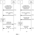
- FIG. 1 shows an uplink communication process or a downlink communication process between UE and a base station in LTE or 5G NR.
- the uplink communication process includes the following steps.
- the UE After performing downlink synchronization with the base station or accessing the base station, the UE receives configuration information of the base station, where the configuration information of the base station includes configuration information such as a time/frequency position of a data signal and a bandwidth.
- the configuration information may be configured by using system information or terminal-specific radio resource control (radio resource control, RRC) information, or may be predefined in a protocol.
- RRC radio resource control
- time information of uplink communication is configured. There may be the following information:
- the time information of uplink communication is predefined in a protocol.
- Table 1b shows time domain resource allocation of a default PUSCH with respect to a normal cyclic prefix.
- Table 1b Row index //row index PUSCH mapping type //PUSCH mapping type, where different types correspond to different resource mapping constraints K 2 //slot offset between DCI and a PUSCH S //start OFDM symbol position of a PUSCH in a slot L //quantity of OFDM symbols of a PUSCH in a slot 1 Type A j 0 14 2 Type A j 0 12 3 Type A j 0 10 4 Type B j 2 10 5 Type B j 4 10 6 Type B j 4 8 7 Type B j 4 6 8 Type A j+1 0 14 9 Type A j+1 0 12 10 Type A j+1 0 10 11 Type A j+2 0 14 12 Type A j+2 0 12 13 Type A j+2 0 10 14 Type B j 8 6 15 Type A j+3 0 14 16 Type A
- the base station sends an uplink grant (uplink grant) to the UE.
- the uplink grant may be specified by using downlink control information (downlink control information, DCI) or radio resource control (radio resource control, RRC) information.
- DCI downlink control information
- RRC radio resource control
- the uplink grant indicates scheduling information such as a time resource, a frequency domain resource, a modulation and coding scheme (modulation coding scheme, MCS) index, and a quantity of transport layers (or a quantity of mapping layers of a transport block) of data.
- scheduling information such as a time resource, a frequency domain resource, a modulation and coding scheme (modulation coding scheme, MCS) index, and a quantity of transport layers (or a quantity of mapping layers of a transport block) of data.
- MCS modulation coding scheme
- MCS modulation coding scheme
- a quantity of transport layers or a quantity of mapping layers of a transport block
- the base station and the terminal may correspondingly send or receive data.
- frequency domain resource scheduling information may be indicated by using a frequency domain resource assignment field (Frequency domain resource assignment) in the DCI.
- Time domain resource scheduling information may further indicate a specific configured value in RRC or a value in a predefined table in a protocol by using a time domain resource assignment field
- P102 The UE sends data to the base station, that is, performs uplink data transmission (PUSCH transmission).
- PUSCH transmission uplink data transmission
- P103 The base station feeds back, to the UE, confirmation about whether the data is successfully received, and feeds back an acknowledgment (acknowledge, ACK) character if the data is successfully received, or feeds back a negative acknowledgment (not acknowledge, NACK) character if the data is not successfully received.
- acknowledge acknowledge
- NACK negative acknowledgment
- the downlink communication process includes the following steps.
- the UE After performing downlink synchronization with the base station or accessing the base station, the UE receives configuration information of the base station, where the configuration information of the base station includes configuration information such as a time/frequency position of a data signal and a bandwidth.
- the configuration information may be configured by using system information or terminal-specific radio resource control (radio resource control, RRC) information, or may be predefined in a protocol.
- RRC radio resource control
- time information of downlink communication is configured. There may be the following information:
- the time information of uplink communication is predefined in a protocol.
- Table 2 shows time domain resource allocation of a default PDSCH with respect to a normal cyclic prefix.
- Table 2 Row index //row index dmrs-TypeA-Position //PDSCH DMRS position PDSCH mapping type //PDSCH mapping type, where different types correspond to different resource mapping constraints K0 //slot offset between DCI and a PDSCH S //start OFDM symbol position of a PDSCH in a slot L //quantity of OFDM symbols of a PDSCH in a slot 1 2 Type A 0 2 12 3 Type A 0 3 11 2 2 Type A 0 2 10 3 Type A 0 3 9 3 2 Type A 0 2 9 3 Type A 0 3 8 4 2 Type A 0 2 7 3 Type A 0 3 6 5 2 Type A 0 2 5 3 Type A 0 3 4 6 2 Type B 0 9 4 3 Type B 0 10 4 7 2 Type B 0 4 4 3 Type B 0 6 4 8 2, 3 Type B 0
- the base station sends a downlink grant (downlink grant) to the UE.
- the downlink grant may be specified by using downlink control information (downlink control information, DCI) or radio resource control (radio resource control, RRC) information.
- DCI downlink control information
- RRC radio resource control
- the downlink grant indicates scheduling information such as a time resource, a frequency domain resource, a modulation and coding scheme (modulation coding scheme, MCS), and a quantity of transport layers (or a quantity of mapping layers of a transport block) of data.
- scheduling information such as a time resource, a frequency domain resource, a modulation and coding scheme (modulation coding scheme, MCS), and a quantity of transport layers (or a quantity of mapping layers of a transport block) of data.
- MCS modulation coding scheme
- MCS modulation coding scheme
- a quantity of transport layers or a quantity of mapping layers of a transport block
- the base station and the terminal may correspondingly send or receive data.
- frequency domain resource scheduling information may be indicated by using a frequency domain resource assignment field (Frequency domain resource assignment) in the DCI.
- Time domain resource scheduling information may further indicate a specific configured value in RRC or a value in a predefined table in a protocol by using a time domain resource assignment field (Time domain resource
- the base station sends data to the UE, that is, performs downlink data transmission (PDSCH transmission).
- PDSCH transmission downlink data transmission
- P203 The UE feeds back, to the base station, confirmation about whether the data is successfully received, and feeds back an acknowledgment (acknowledge, ACK) character if the data is successfully received, or feeds back a negative acknowledgment (not acknowledge, NACK) character if the data is not successfully received.
- acknowledge acknowledge
- NACK negative acknowledgment
- channel coding is performed on data to ensure data transmission reliability and spectral efficiency.
- PUSCH-based uplink data communication may relate to a message 3 in a random access process, or other uplink data or messages carried on a PUSCH.
- the messages After a process such as channel coding is performed on these messages at a physical layer, the messages correspondingly become physical signals, and the signals are sent from a transmit antenna at a transmit end.
- a corresponding reverse process is performed at a receive end to restore, so as to implement communication.
- a channel coding manner may be low density parity check (low density parity check, LDPC) coding.
- Transport Block Data sent from a medium access control (medium access control, MAC) layer to the physical layer is organized in a form of a transport block (Transport Block, TB).
- One TB corresponds to one data block including a medium access control protocol data unit (Medium access control Protocol data unit, MAC PDU).
- the transport block may be data in uplink communication (for example, sent by UE to a base station), and is carried by an uplink shared channel (uplink shared channel, UL-SCH), for example, a PUSCH; or may be data in downlink communication (for example, sent by a base station to UE), and is carried by a downlink shared channel (downlink shared channel, DL-SCH), for example, a PDSCH.
- one transport block may usually include a plurality of protocol data units.
- one transport block is further processed into one or more code blocks (code block) through channel coding.
- code block is a unit for performing channel coding on data. To be specific, channel coding and rate matching (and interleaving) are performed on bits of one code block together.
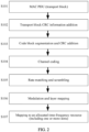
- FIG. 2 shows a physical layer data processing process, which is applicable to the foregoing uplink communication, and may be performed by a terminal device serving as a transmit end; or may be applicable to the foregoing downlink communication, and may be performed by a network device serving as a transmit end. The process mainly includes the following steps.
- S101 Send a higher layer data packet (MAC PDU), or referred to as a transport block, to a physical layer.
- MAC PDU higher layer data packet
- S102 Add (attach) cyclic redundancy check (cyclic redundancy check, CRC) information to the transport block at the physical layer, to generate a second transport block.
- CRC cyclic redundancy check
- whether to add CRC information to the plurality of code blocks is determined based on a value of C.
- C because the code block is equivalent to the original transport block, UE does not need to add CRC information to the code block 1 obtained through block segmentation on the second transport block.
- C is greater than 1, the UE may add CRC information to the C code blocks.
- S104 Separately perform channel coding on the C code blocks 1, to generate C code blocks 2.
- S105 Perform rate matching (rate matching) or scrambling (scrambling) on the C code blocks 2, to generate C code blocks 3.
- S107 Map code blocks 3 obtained through modulation and layer mapping to an allocated time-frequency resource, to implement uplink data transmission or downlink data transmission.
- the UE sends a PUSCH to a base station, the PUSCH may be carried on the time-frequency resource to which the code block 3 is mapped, and the PUSCH includes the code block 3.
- the base station sends a PDSCH to the UE, the PDSCH may be carried on the time-frequency resource to which the code block 3 is mapped, and the PUSCH includes the code block 3.
- the time-frequency resource is related to the time domain resource and the frequency domain resource scheduled by the uplink grant in P101.
- the time-frequency resource is related to the time domain resource and the frequency domain resource scheduled by the downlink grant in P201.
- G represents a total quantity of bits after the transport block is coded
- G N L ⁇ Q m ⁇ N RE
- N L is a quantity of mapping layers of the transport block
- Q m is a modulation order
- N RE is a quantity of resource elements (resource element, RE) to which the transport block is mapped.
- C is a quantity of code blocks 1 or code blocks 2.
- the code blocks of the different redundancy versions may be transmitted during repeated transmission or retransmission.
- Channel coding in uplink communication or downlink communication relates to determining of a transport block size (transport block size, TBS), a code block length, and a quantity of code blocks. It should be understood that a receive end performs a reverse operation of the foregoing process, to restore the transport block. The following describes a manner used in the conventional technology.
- the size of the transport block in S101 may be determined based on a time domain resource, a frequency domain resource, a modulation and coding scheme, and a quantity of transport layers (and/or a quantity of ports, denoted as N L ) indicated in an uplink grant or a downlink grant.
- the modulation and coding scheme indicated in the uplink grant or the downlink grant may be MCS index information.
- the MCS index information indicates information such as a modulation order Qm, a target code rate R, and spectral efficiency.
- the uplink grant may indicate an MCS index table of a PUSCH based on change precoding and 64QAM in Table 3 or Table 4, or a row in an MCS index table that may be used as a PUSCH in Table 5.
- the downlink grant may indicate a row in an MCS index table that may be used as a PDSCH in any one of Table 5 to Table 7.
- Table 6 is used to determine a modulation and coding scheme.
- Table 4 uplink communication
- Table 7 downlink communication
- Table 3 uplink communication and based on discrete Fourier transform-spread-OFDM, that is, DFT-s-OFDM
- Table 5 downlink communication or uplink communication and based on OFDM
- step a1 to step e1 a manner for determining a size of the transport block in S101 in the related technology.
- N L is a quantity (represented by a symbol ⁇ in a protocol) of mapping layers of the transport block
- ⁇ is a quantity of resource elements (resource element, RE) to which the transport block is mapped
- R is a target code rate
- Q m is a modulation order.
- N RE is determined in the following manner.
- N' RE,k is determined.
- N' RE,k may be understood as a quantity of REs allocated to a PUSCH or a PDSCH in each PRB (whose index is denoted as k) in scheduled time.
- N' RE,K N SC RB ⁇ N symb sh ⁇ N DMRS PRB ⁇ N oh PRB .
- N symb sh represents a quantity of scheduled OFDM symbols in each RB (or RBG) in one slot ( N symb sh is the number of symbols of the PDSCH allocation within the slot).
- N DMRS PRB represents a quantity of REs for a DMRS in each PRB in one slot ( N DMRS PRB is the number of REs for DM-RS per PRB in the scheduled duration including the overhead of the DM-RS CDM groups without data).
- N oh PRB represents a quantity of overheads in each RB (or RBG) in one slot ( N oh PRB is the overhead configured by higher layer parameter xOverhead in PDSCH-ServingCellConfig. If the xOverhead in PDSCH-ServingCellconfig is not configured (a value from 0, 6, 12, or 18), the N oh PRB is set to 0), for example, a quantity of overheads used for reference signal CSI-RS transmission. For details, refer to descriptions in the protocol TS 38.214.
- the UE determines a value of the transport block size according to the following step c and step d (denoted as case 1).
- the UE determines a value of the transport block size according to the following step e and step f (denoted as case 2).
- case 1 and case 2 The following separately describes in detail case 1 and case 2.
- the UE determines the value of the transport block size according to the following step c and step d.
- n max 3 , ⁇ log 2 N info ⁇ ⁇ 6 .
- Step d1 The UE may query, according to transport block size values recorded in Table 8, a maximum value that is not greater than N' info , and use the maximum value as the value of the transport block size. For example, if N' info determined according to the foregoing formula is 1200, it can be learned by querying Table 8 that a maximum value that is not greater than 1200 is 1192. In this case, the transport block size is 1192 bits (bit). Table 8 is used as an example to show a correspondence between an index and a transport block size.
- n ⁇ log 2 N info ⁇ 24 ⁇ ⁇ 5 .
- Step f1 Determine the value (which may be denoted as A described in S102 or TBS) of the transport block size based on the target code rate R and N' info .
- TBS 8 ⁇ C ′ ⁇ ⁇ N ′ info + 24 8 ⁇ C ′ ⁇ ⁇ 24 .
- C ′ ⁇ N ′ info + 24 3816 ⁇ .
- TBS 8 ⁇ C ′ ⁇ ⁇ N ′ info + 24 8 ⁇ C ′ ⁇ ⁇ 24 .
- C' ⁇ N ′ info + 24 8424 ⁇ .
- TBS 8 ⁇ ⁇ N ′ info + 24 8 ⁇ ⁇ 24 .
- C' is a variable for temporarily determining a code block size.
- the following further describes a manner for determining the quantity of code blocks in S103 in a related technology.
- a channel coding LDPC base graph (LDPC base graph) needs to be determined.
- a base graph 1 there are two types of base graphs: a base graph 1 and a base graph 2, which respectively correspond to different channel coding parameters.
- a method for determining a base graph is as follows: When the transport block size is A ⁇ 292, or when the transport block size is A ⁇ 3824 and the target code rate is R ⁇ 0.67, or when the target code rate is R ⁇ 0.25, the base graph 2 is used; otherwise, the base graph 1 is used.
- a quantity C of code blocks obtained by segmenting a transport block may be determined based on a selected base graph and a length B of a second transport block.
- a coding gain is related to a code block length. For example, a longer code block length indicates a higher coding gain, and a shorter code block length indicates a lower coding gain.
- the code block length is limited by a transport block size. It can be learned from the foregoing steps a to e that, in the related technology, a transport block is usually mapped to a single slot for transmission, or a single redundancy version obtained through channel coding on a transport block is sent by using one slot. In a coverage-limited scenario, if a bandwidth scheduled for a terminal is low and an MCS is low, a data block that can be transmitted is small, and a total coding gain is reduced.
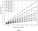
- FIG. 3 shows a correspondence between a transport block size and a quantity of schedulable symbols.
- a maximum of 14 OFDM symbols used to transmit data are scheduled in one slot.
- a maximum of one transport block is less than 1750 bits, and is far less than the maximum code block length 3824 corresponding to the base graph 2 and far less than the maximum code block length 8448 corresponding to the base graph 1. Consequently, a channel coding gain is low, more CRC overheads are introduced, and transmission performance optimization space is limited.
- the code block length K is related to a (nominal or actual) total quantity (that is, N RE ) of resources to which the transport block is mapped and a modulation and coding scheme indicated by the MCS index.
- a code block length K corresponding to a same MCS index gradually increases with N RE , but a turning point occurs in a specific case.
- FIG. 4 is a schematic diagram of a relationship between a code block length and a quantity of mapped resources (or referred to as a quantity N RE of mapped resource elements).
- N RE is related to scheduling of a bandwidth and a time domain resource (a quantity of OFDM symbols) by a base station in a configuration process or an uplink/downlink grant process.
- this application provides a data transmission method and apparatus.
- a quantity of resources to which a transport block can be mapped is adjusted for different MCSs, to determine a transport block size, a code block length, and the like, thereby improving a channel coding gain, reducing CRC overheads, and improving communication performance.
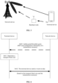
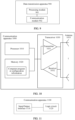
- the data transmission method provided in embodiments of this application may be applied to a communication system architecture shown in FIG. 5 .
- the communication system includes a network device and a terminal device.
- the communication system may further include a backhaul node.
- the backhaul node may communicate with the network device, and may communicate with the terminal device.
- the backhaul node may be considered as a terminal device and accesses the network device.
- the backhaul node may be considered as a network device and provides a relay service for the terminal device, and the terminal device may access the network device through the backhaul node.
- Solution 1 An embodiment of this application provides a data transmission method. The method may be applied to the foregoing network device or terminal device, to implement a data processing process related to channel coding in uplink communication or downlink communication.
- FIG. 6 mainly focuses on an operation performed on a terminal device side, and mainly includes the following steps.
- a terminal device determines a transport block size.
- the transport block size is related to a first parameter, or the transport block size is determined by a first parameter.
- the first parameter includes at least one of the following: a modulation and coding scheme, configuration information of a transmission resource, a quantity N RE of resources to which a transport block is mapped, a quantized intermediate value N' info , a transport block size TBS, and a channel-coded code block length K.
- the first parameter is related to a second parameter
- the second parameter includes at least one of the following: an upper limit value N RE Th of the quantity of resources to which the transport block is mapped, an upper limit value T tb Th of the transport block size, an upper limit value N ′ info Th of the intermediate quantized value, and an upper limit value K Th of a channel-coded code block length.
- an upper limit value of a related parameter may also be referred to as a nominal value, a reference value, a preset constant, or a constant indicated by configuration information.
- the upper limit value of the quantity of resources to which the transport block is mapped may also be referred to as a nominal value of the quantity of resources to which the transport block is mapped; the upper limit value of the transport block size may also be referred to as a nominal value of the transport block size; the upper limit value of the quantized intermediate value may also be referred to as a first nominal quantized intermediate value; and the upper limit value of the channel-coded code block length may also be referred to as a nominal code block length.
- the terminal device may determine the transport block size in the following manner: The terminal device obtains the modulation and coding scheme, the configuration information of the transmission resource, and the second parameter; the terminal device determines the first parameter based on the modulation and coding scheme, the configuration information of the transmission resource, and the second parameter; and the terminal device determines the transport block size based on the first parameter.
- the second parameter may be set in a predefined manner.
- second parameters associated with different MCSs may be set, and the MCS index tables shown in Table 3 to Table 7 may be extended, to record the upper limit values of the foregoing related parameters in the tables.
- a solution of adding and recording an upper limit value of a related parameter in an MCS index table is described in solution 2.
- a second parameter associated with an MCS may be determined based on a quantity of resource elements corresponding to a turning point corresponding to the MCS in FIG. 4 .
- the upper limit value N RE Th of the quantity of resources to which the transport block is mapped may be set to a quantity that is of resources to which the transport block is mapped and that corresponds to a first turning point on a curve corresponding to the MCS index 0.
- N RE Th may be an upper limit value of the quantity of resource elements that causes an increase in a quantity of code blocks of the transport block.
- resource quantities N RE Th and NRE + 1 correspond to different quantities of channel-coded code blocks (or different quantities of blocks divided from the transport block).
- a manner in which the terminal device obtains the modulation and coding scheme may be as follows: The terminal device obtains an uplink grant or a downlink grant from a network device, where the uplink grant or the downlink grant includes indication information indicating the modulation and coding scheme. For example, the terminal device receives DCI from the network device.
- the DCI includes an MCS index of the modulation and coding scheme. If the DCI is used for uplink grant scheduling, the MCS index included in the DCI may be an MCS index in a row in Table 3, Table 4, or Table 5. If the DCI is used for downlink grant scheduling, the MCS index included in the DCI may be an MCS index in a row in Table 5, Table 6, or Table 7.
- Parameters of the modulation and coding scheme include a target code rate R, a modulation order Q m , and the like corresponding to the MCS index.
- the transmission resource may be a time domain resource or a frequency domain resource indicated by the network device in an uplink grant or a downlink grant (or an RRC message, or a medium access control-control element (medium access control-control element, MAC-CE) message).
- the transmission resource may include one or more slots.
- the configuration information of the transmission resource includes at least one of the following configuration information: time domain resource allocation information, frequency domain resource allocation information, a mapping type, a bandwidth, and the like.
- the configuration information includes but is not limited to the configuration information in P100/P101 or P200/P201.
- FIG. 6 further shows step S600: The network device sends an uplink grant/downlink grant to the terminal device, where the uplink grant/downlink grant carries an MCS and the configuration information of the transmission resource.
- a dashed line indicates that S600 is an optional step.
- the transmission resource includes a plurality of slots, for time domain resources and frequency domain resources allocated by using the uplink grant or the downlink grant, as shown in FIG. 7a , time domain resource allocations and frequency domain resource allocations in different slots may be the same.
- different slots have different frequency domain resources but a same time domain resource.
- FIG. 7c different slots have different time domain resources but a same frequency domain resource.
- different slots have different frequency domain resources and different time domain resources.
- a first part of time domain resources is allocated to a transport block, and a second part of time domain resources is allocated to another transport block.
- the network device may use indication/configuration information (for example, an uplink grant, a downlink grant, an RRC message, or a MAC-CE message) to carry at least one of the following parameters: a transport block mapping manner (that is, mapping a transport block to a single slot (TB processing over single-slot), or mapping a transport block to a plurality of slots (TB processing over multi-slot), or mapping a transport block to N slots (TB processing over N slots)), a quantity N of slots to which the transport block is mapped, a mapped OFDM start symbol S, a quantity L of consecutively mapped OFDM symbols, and a total quantity F of OFDM symbols to which the transport block is mapped.
- a transport block mapping manner that is, mapping a transport block to a single slot (TB processing over single-slot), or mapping a transport block to a plurality of slots (TB processing over multi-slot), or mapping a transport block to N slots (TB processing over N slots)
- a transport block mapping manner that is, mapping
- the terminal device may determine the transport block, the quantity of code blocks, the code block size, and the quantity N of slots based on one or more of the mapping manner, N, S, L, and F obtained from the indication information (for example, the uplink grant or the downlink grant).
- the transport block, the quantity of code blocks, the code block size, and the quantity N of slots are determined based on at least one of N, S, L, and S+L.
- the transport block, the quantity of code blocks, the code block size, and the quantity N of slots are determined based on at least one of S, L, and S+L.
- a transmission manner in which the transport block is mapped to a plurality of slots or the transport block is mapped to N may include but is not limited to the following manners: (1) Multi-slot is indicated if S and L satisfy the following condition: S+L>X, where X is an integer. For example, X is greater than a predefined value. For example, X>14. For another example, X>20. (2) The transport block, the quantity of code blocks, the code block size, and the quantity N of slots are determined based on F and a specified symbol position used to transmit the transport block, where F satisfies the following condition: F is greater than a predefined value. For example, F is greater than 12.
- F is greater than 14.
- F is greater than 20. It indicates that all F OFDM symbols used to transmit the transport block in the N slots jointly form one transmission occasion (transmission occasion). (3)
- the configuration information of the network device indicates that the transport block is mapped to N>1 slots. (4) A manner of determining the quantity N of slots may alternatively be determined in a manner in solution 4 or solution 5.
- the transport block mapping manner may also be referred to as a transport block transmission manner. Mapping a transport block to a plurality of slots is also referred to as mapping a transport block to N slots, where N>1. Mapping a transport block to a plurality of slots means that the transport block is transmitted by using the plurality of slots.
- the transport block mapping manner may also be referred to as a transport block segmentation manner (that is, the transport block is segmented into a plurality of channel-coded code blocks).
- a quantity of blocks may not be limited, or a maximum quantity of blocks may be limited. It should be understood that these terms correspond to a same processing manner in this embodiment of this application.
- the transport block mapping manner may be configured by using a time domain resource allocation field.
- a mapping type mappingType may be used for indication. For example, a new candidate item is added to a mapping type mappingType field, and corresponding RRC signaling is:
- N, S, L, and F refer to a quantity of slots or OFDM symbols corresponding to a subcarrier spacing used for transmitting the indication information.
- N, S, L, and F refer to a quantity of slots or OFDM symbols corresponding to a subcarrier spacing used for transmitting the indication data.
- N, S, L, and F refer to a quantity of slots or OFDM symbols corresponding to a reference subcarrier spacing, and the reference subcarrier spacing is determined based on network configuration information.
- the second parameter may be used by the terminal device to determine a coding scheme of the transport block. For example, the terminal device may perform channel coding on the transport block based on the upper limit value of the channel-coded code block length and the transport block size, to obtain n channel-coded code blocks corresponding to the transport block, where a length of any one of the n channel-coded code blocks is less than or equal to the upper limit value of the channel-coded code block length, where n is a positive integer.
- a difference between the upper limit value of the transport block size and the upper limit value of the channel-coded code block length may be set to be greater than a specified threshold, and n is 1.
- a value of the specified threshold may be related to a quantity of bits of CRC information added to the transport block, and the threshold needs to be greater than or equal to a quantity of bits required by the CRC information. In this way, a relatively long code block length can be ensured. This helps improve a coding gain.
- the terminal device sends or receives data on the transmission resource based on the transport block size.
- the terminal device may send or receive data on the transmission resource based on the n channel-coded code blocks.
- the terminal device may send or receive data on the transmission resource based on the n channel-coded code blocks.
- an upper limit value is set for a parameter that participates in determining the transport block size, to adjust the transport block size, so as to avoid a case in which a quantity of mapped resources is relatively large but a code block length is relatively small, and avoid a case in which the transport block is divided into more small code blocks, and consequently a channel coding gain is lost and more CRC overheads are introduced.
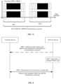
- FIG. 8 mainly focuses on an operation performed on a network device side, and mainly includes the following steps.
- a network device determines a transport block size.
- the transport block size is related to a first parameter, or the transport block size is determined by a first parameter.
- the first parameter includes at least one of the following: a modulation and coding scheme, configuration information of a transmission resource, a quantity N RE of resources to which a transport block is mapped, a quantized intermediate value N' info , a transport block size TBS, and a first channel-coded code block length K.
- the first parameter is related to a second parameter, and the second parameter includes at least one of the following: an upper limit value NRE of the quantity of resources to which the transport block is mapped, an upper limit value T tb Th of the transport block size, an upper limit value N ′ info Th of the intermediate quantized value, and an upper limit value K Th of a channel-coded code block length.
- the network device may determine the transport block size in the following manner: The network device obtains the modulation and coding scheme, the configuration information of the transmission resource, and the second parameter; the network device determines the first parameter based on the modulation and coding scheme, the configuration information of the transmission resource, and the second parameter; and the terminal device determines the transport block size based on the first parameter.
- the network device obtains the second parameter
- the network device obtains the modulation and coding scheme and the configuration information of the transmission resource.
- the network device may determine, based on a communication requirement between the network device and the terminal device, performance of the terminal device, and the like, a modulation and coding scheme and a transmission resource that are applicable to be scheduled (or configured or allocated) to the terminal device. Further, optionally, the network device may indicate the modulation and coding scheme and the configuration information of the transmission resource to the terminal device by using an uplink grant or a downlink grant. For a specific indication manner, refer to the implementation in which the terminal device obtains the modulation and coding scheme and the configuration information of the transmission resource in S601. Details are not described in this embodiment of this application. Similarly, for example, FIG.
- step S800 The network device sends an uplink grant/downlink grant to the terminal device, where the uplink grant/downlink grant carries an MCS and the configuration information of the transmission resource.
- a dashed line indicates that S800 is an optional step. It should be noted that S800 may be performed in parallel with S801, or may be performed before or after S801. This is not limited in this embodiment of this application.
- the downlink grant in step S800 may be used by the terminal device to decode received data, and the uplink grant in step S800 may be used by the terminal device to encode to-be-sent data.
- the second parameter may be used by the network device to determine a transport block coding scheme, for example, determine n channel-coded code blocks corresponding to the transport block, and a code block size.
- a transport block coding scheme for example, determine n channel-coded code blocks corresponding to the transport block, and a code block size.
- the network device receives or sends data on the transmission resource based on the transport block size.
- the network device may receive or send data on the transmission resource based on the n channel-coded code blocks.
- an upper limit value is set for a parameter that participates in determining the transport block size, to adjust the transport block size, so as to avoid a case in which a quantity of mapped resources is relatively large but a code block length is relatively small, and avoid a case in which the transport block is divided into more small code blocks, and consequently a channel coding gain is lost and more CRC overheads are introduced.
- a second parameter is set, that is, at least one second parameter has a correspondence with a modulation and coding scheme (or an MCS index).
- the second parameter may also be understood as an upper limit value (or referred to as a nominal value, a reference value, or another term) of a related parameter, to avoid a case in which a code block length jumps (decreases) and a coding gain decreases.
- the foregoing related parameter may include at least one of the following parameters: a transport block size TBS, a quantized intermediate value N' info , a code block length K for channel coding, and a quantity N RE of resources to which a transport block is mapped.
- an uplink grant may indicate an MCS index in any one of Table 9 to Table 11
- a downlink grant may indicate an MCS in any one of Table 11 to Table 13.
- a terminal device may obtain, based on the MCS index indicated by the uplink grant or the downlink grant, other information in a row in which the MCS index is located, for example, one or more of a modulation order, a target code rate, an upper limit value T tb Th of the transport block size, an upper limit value N ′ info Th of the quantized intermediate value of a quantity of information bits, an upper limit value K Th of the code block length, an upper limit value N RE Th of the quantity of resources to which the transport block is mapped, and a base graph; and specifically determine, based on a selected base graph, the modulation and coding scheme and first information associated with the modulation and coding scheme.
- the upper limit value T tb Th of the transport block size, the upper limit value N ′ info Th of the quantized intermediate value of the quantity of information bits, and the upper limit value K Th of the code block length are related to the target code rate.
- the upper limit value T tb Th of the transport block size is 3752; otherwise, the upper limit value T tb Th of the transport block size is 8192.
- the upper limit value N ′ info Th of the quantized intermediate value of the quantity of information bits is 3808; otherwise, the upper limit value N ′ info Th of the quantized intermediate value of the quantity of information bits is 8192.
- the upper limit value K Th of the code block length is 3776; otherwise, the upper limit value K Th of the code block length is 8216.
- At least one of the following is related to an MCS table: the upper limit value T tb Th of the transport block size, the upper limit value N ′ info Th of the quantized intermediate value of the quantity of information bits, the upper limit value K Th of the code block length, the upper limit value N RE Th of the quantity of resources to which the transport block is mapped, and the base graph.
- a manner of selecting the MCS table may be the same as that in the conventional technology.
- an association relationship between an MCS index and other information in a row in which the MCS index is located is not limited.
- the other information may be one row or several rows shown in the table, all rows in the table, or more rows than those shown in the table.
- the other information associated with the MCS index may be one column or several columns shown in the table, all columns in the table, or more columns than those shown in the table.
- the following Table 9 to Table 13 are used as an example, and do not indicate that descriptions of the association between an MCS index and other information in this embodiment of this application are limited to this example.
- Solution 3 The following describes in detail a manner of determining parameters such as a transport block size, a code block length, and a quantity of code blocks in S602. The following steps a2 to f2 are mainly included.
- N L is a quantity of mapping layers of a transport block
- N RE is a quantity of resources to which the transport block is mapped and may be specifically a quantity of resource elements (resource element, RE) to which the transport block is mapped
- R is a target code rate
- Q m is a modulation order.
- N RE * may be understood as a quantity (actual or nominal (nominal)) of resources to which the transport block can be mapped.
- N RE * is determined in the foregoing first manner or second manner.
- a value of N RE Th is at least one value in Table 9 to Table 13.
- N RE * may be determined with reference to a manner of determining N RE in the foregoing related technology. Specifically, the solution for determining N RE in the foregoing step a1 may be used.
- N RE * may be determined with reference to manners in the following examples 1 to 4.
- N' RE,k may be determined in the following manner.
- N' RE,k may be understood as a quantity of REs allocated to a PUSCH (or PDSCH) in a PRB (an index is denoted as k).
- N ′ RE , k N ⁇ N SC RB ⁇ N symb , k sh ⁇ N DMRS , k PRB ⁇ N oh , k PRB .
- N symb , k sh represents a quantity of scheduled OFDM symbols of a k th RB (an RB may be used as a granularity, or an RBG may be used as a granularity) in one slot.
- N oh , k PRB represents a quantity of overheads of the k th RB (or RBG) in one slot, for example, a quantity of overheads used for CSI-RS transmission.
- N ′ RE N ⁇ N SC RB ⁇ N symb sh ⁇ N DMRS PRB ⁇ N oh PRB .
- a value of N SC RB is a fixed value.
- N SC RB 12 .
- N symb sh represents a quantity of scheduled OFDM symbols of each RB (or RBG) in one slot.
- N oh PRB represents a quantity of overheads of each RB (or RBG) in one slot, for example, a quantity of overheads used for CSI-RS transmission.
- N' RE,k is determined in the following manner based on a quantity of OFDM symbols (or OFDM symbol positions) and a quantity of frequency domain resource blocks (or resource block positions) in a first slot (or a nominal slot) (that is, whether quantities and positions of N time domain resources and frequency domain resources are the same is not considered).
- N' RE,k may be understood as a quantity of REs allocated to a PUSCH (or PDSCH) in a PRB (an index is denoted as k) in the first slot.
- N' RE,k N ⁇ N SC RB ⁇ N symb , k sh ⁇ N DMRS , k PRB ⁇ N oh , k PRB .
- N SC RB is a fixed value, and may represent a quantity of subcarriers included in one PRB in frequency domain.
- N SC RB 12.
- N symb , k sh represents a quantity of scheduled OFDM symbols of a k th RB (an RB may be used as a granularity, or an RBG may be used as a granularity) in the first slot.
- N oh , k PRB represents a quantity of overheads of the k th RB (or RBG) in the first slot, for example, a quantity of overheads used for CSI-RS transmission.
- N ′ RE N ⁇ ( N SC RB ⁇ N symb sh ⁇ N DMRS PRB ⁇ N oh PRB ) .
- a value of N SC RB is a fixed value.
- N SC RB 12 .
- N symb sh represents a quantity of scheduled OFDM symbols of each RB (or RBG) in the first slot.
- N oh PRB represents a quantity of overheads of each RB (or RBG) in the first slot, for example, a quantity of overheads used for CSI-RS transmission. It may be understood that, English corresponding to this solution may be briefly described as: Based on the number of REs determined in the first L symbols over which the TBoMS (TB processing over multi-slot) transmission is allocated, scaled by N ⁇ 1.
- N' RE,k may be determined in the following manner.
- N' RE,k may be understood as a quantity of REs allocated to a PUSCH (or PDSCH) in a PRB (an index is denoted as k).
- a value of N SC RB is a fixed value.
- N SC RB 12 .
- N symb , k sh s represents a quantity of scheduled OFDM symbols of a k th RB (or RBG) in a slot s.
- N oh , k PRB s represents a quantity of overheads of the k th RB (or RBG) in the slot s, for example, a quantity of overheads used for CSI-RS transmission.
- N SC RB is a fixed value.
- N SC RB 12 .
- N symb sh s represents a quantity of scheduled OFDM symbols of each RB (or RBG) in a slot s.
- N oh PRB s represents a quantity of overheads of each RB (or RBG) in the slot s, for example, a quantity of overheads used for CSI-RS transmission.
- N' RE,k ( s ) is a quantity of REs allocated to a PUSCH (or PDSCH) in a PRB (an index is denoted as k) in a slot s
- a quantity of PRBs scheduled in the slot s is denoted as n PRB (s)
- a quantity of REs scheduled and allocated to a PUSCH (or PDSCH) in the slot s is denoted as n PRB ( s ), that is, a total quantity of resources in N slots to which the transport block is mapped is N RE .
- N symb ,k sh s represents a quantity of scheduled OFDM symbols of a k th RB (or RBG) in the slot s.
- N oh ,k PRB s represents a quantity of overheads of the k th RB (or RBG) in the slot s, for example, a quantity of overheads used for CSI-RS transmission.
- N symb sh represents a quantity of scheduled OFDM symbols of each RB (or RBG) in each slot s.
- N oh PRB represents a quantity of overheads of each RB (or RBG) in each slot s, for example, a quantity of overheads used for CSI-RS transmission. It may be understood that, English corresponding to this solution may be briefly described as: Based on all REs determined across the symbols or slots over which the TBoMS transmission is allocated.
- the first information includes an upper limit value NRE of the quantity of resources to which the transport block is mapped
- the quantity N RE of resources to which the transport block is mapped is related to the upper limit value NRE of the quantity of resources to which the transport block is mapped
- N info is related to N RE Th .
- Step b2 Determine a quantized intermediate variable N' info based on the unquantized intermediate variable N info .
- the UE determines a value of the TBS according to the following step c2 and step d2 (denoted as case 1).
- N info > 3824 the UE determines a value of the TBS according to the following step e2 and step f2 (denoted as case 2).
- the value of the transport block size is determined according to the following step c and step d.
- n max 3 , ⁇ log 2 N info ⁇ ⁇ 6 .
- a value of N ′ info Th is at least one value in Table 9 to Table 13.
- Step d2 The UE may query, according to a preset candidate transport block size set, for example, Table 8, a maximum value that is not greater than N' info , and use the maximum value as the value of the transport block size, which is denoted as TBS.
- TBS a preset candidate transport block size set, for example, Table 8, a maximum value that is not greater than N' info , and use the maximum value as the value of the transport block size, which is denoted as TBS.
- N' info determined according to the foregoing formula is 1200
- the TBS is 1192 bits (bit).
- Table 8 is used as an example.
- a correspondence between an index and a TBS is not limited in this embodiment of this application.
- the first information includes the upper limit value T tb Th of the transport block size
- the transport block size TBS is related to the upper limit value T tb Th of the transport block size.
- a value of T tb Th is at least one value in Table 9 to Table 13.
- T tb Th 3752 , or 3824, or 3728, or 3800.
- Step e2 Calculate the quantized intermediate value N' info of the quantity of information bits (quantized intermediate number of information bits).
- N' info is related to at least one of the following parameters: N ′ info Th , T tb Th , and K Th .
- N' info is related to at least one of the following parameters: N ′ info Th and C 0 .
- N info ⁇ C 0 ⁇ N ′ info Th
- N ′ info min ( N ′ info Th , 2 n ⁇ round N info ⁇ 24 2 n ) .
- n ⁇ log 2 N info ⁇ 24 ⁇ ⁇ 5 .
- N info C 0 ⁇ min ( N ′ info Th , 2 n ⁇ round N info ⁇ 24 2 n ) .
- n ⁇ log 2 N info ⁇ 24 ⁇ ⁇ 5 .
- N info ⁇ C 0 ⁇ N ′ info Th
- N ′ info min ( C 0 ⁇ N ′ info Th , 2 n ⁇ round N info ⁇ 24 2 n )
- n ⁇ log 2 N info ⁇ 24 ⁇ ⁇ 5 .
- a value of N ′ info Th is at least one value in Table 9 to Table 13.
- N N is greater than 1
- n ⁇ log 2 N info ⁇ 24 ⁇ ⁇ 5 .
- C 0 is a predefined constant, or the parameter is determined based on configuration information.
- C 0 1, and one transport block is allowed to be transmitted on a scheduled resource by using at most one code block.
- the code block length can be maximized, thereby maximizing a coding gain and transmission performance.
- C 0 2
- one transport block is allowed to be transmitted on a scheduled resource by using at most two code blocks.
- the code block length can be maximized, thereby maximizing a coding gain and transmission performance.
- N' into is related to at least one of the following parameters: N ′ info Th , C 0 , N ′ info Th 0 , N ′ info Th 1 , or N ′ info Th 2 .
- N ′ info Th C 0 , N ′ info Th 0 , N ′ info Th 1 , or N ′ info Th 2 .
- N ′ info max 3840,2 n ⁇ round N info ⁇ 24 2 n
- N ′ info max 3840,2 n ⁇ round N info ⁇ 24 2 n
- N ′ info Th 0 , N ′ info Th 1 , and N ′ info Th 2 are non-negative values.
- N ′ info Th 0 , N ′ info Th 1 , and N ′ info Th 2 are parameters related to a quantity of channel-coded code blocks (for example, C 0 ), and settings of the parameters correspondingly maximize a channel coding length (and a corresponding channel coding gain).
- Step f2 Determine the value TBS of the transport block size based on the target code rate R and N' into (TBS is A, TBS is used in the protocol 38.214, Ais used in the protocol 38.212, and TBS and A may be considered the same).
- a value of T tb Th is at least one value in Table 9 to Table 13.
- C 0 is a predefined constant, or the parameter is determined based on configuration information.
- C 0 herein may be the same as C 0 in step e2.
- C 0 1, and one transport block is allowed to be transmitted on a scheduled resource by using at most one code block.
- the code block length can be maximized, thereby maximizing a coding gain and transmission performance.
- C 0 2
- one transport block is allowed to be transmitted on a scheduled resource by using at most two code blocks.
- the code block length can be maximized, thereby maximizing a coding gain and transmission performance.
- TBS is related to T tb Th and/or C 0 .
- C 0 is a predefined constant, or the parameter is determined based on configuration information.
- C 0 herein may be the same as C 0 in step e2.
- C 0 1, and one transport block is allowed to be transmitted on a scheduled resource by using at most one code block.
- the code block length can be maximized, thereby maximizing a coding gain and transmission performance.
- C 0 2
- one transport block is allowed to be transmitted on a scheduled resource by using at most two code blocks.
- the code block length can be maximized, thereby maximizing a coding gain and transmission performance.
- TBS 8 ⁇ ⁇ N ′ info + 24 8 ⁇ ⁇ 24 .
- the transport block can be prevented from being divided into code blocks whose quantity exceeds a specified quantity of code blocks, thereby ensuring a code block length and a corresponding channel coding gain.
- the quantity of code blocks and the code block length are related to at least one of the following parameters: T tb Th , C 0 , N' info , and K Th .
- T tb Th the quantity of code blocks (C in S103, where a calculation manner may be the same as that in an existing protocol) is fixed to 1, and the code block length is the codeword length obtained after TBS coding and determined in the foregoing step.
- the code block length can be kept in a relatively large range, so that a coding gain is higher.
- impact on the protocol is small.
- any method in this embodiment is used only when a manner of mapping the transport block to N slots is enabled.
- a first channel-coded code block quantity corresponding to the transport block is 1, and a first channel-coded code block length K is equal to the upper limit value K Th of the channel-coded code block length.
- a value of N ′ info Th is at least one value in Table 9 to Table 13.
- a value of T tb Th is at least one value in Table 9 to Table 13. In an implementation, a value of K Th is at least one value in Table 9 to Table 13.
- any method in this embodiment is used only when the transport block is sent by using a single layer (or a single antenna port).
- Solution 4 For a solution of determining a quantity N of slots, a quantity of OFDM symbols used for transport block transmission, a quantity of OFDM symbols for determining a transport block size, or a quantity of slots for determining a transport block size, refer to the following manner 1 or manner 2 for implementation.
- a quantity N of slots is related to time domain resource allocation and an MCS.
- N RE Th there is a relatively strong association between N RE Th and an MCS index.
- a larger MCS index corresponds to a smaller value of N RE Th .
- a smaller quantity of required time-frequency resources indicates a smaller quantity of time-frequency resources required to reach an upper limit value for not performing code block segmentation.
- different MCSs, different scheduling bandwidths n PRB , and a quantity of required OFDM symbols are defined in a predefined manner to indicate the quantity N of slots.
- Table 15 to Table 19 are used as examples. Quantities F of OFDM symbols in these tables respectively correspond to maximum quantities of OFDM symbols for not performing code block segmentation in different MCSs and scheduling bandwidths (quantities n P RB of resource blocks) (that is, for F+1, a transport block is segmented into more code blocks).
- an uplink grant may indicate an MCS index in any one of Table 15 to Table 17.
- a downlink grant may indicate an MCS index in any one of Table 17 to Table 19.
- a terminal device may learn, based on the scheduling bandwidth and the MCS index indicated by the uplink grant or the downlink grant, parameters such as a modulation order and a target code rate of a modulation and coding scheme identified by the MCS index, and a quantity of required OFDM symbols corresponding to the scheduling bandwidth (or a quantity of slots corresponding to the quantity of required OFDM symbols).
- an association relationship between an MCS index and other information in a row in which the MCS index is located is not limited.
- the other information may be one row or several rows shown in the table, all rows in the table, or more rows than those shown in the table.
- the other information associated with the MCS index may be one column or several columns shown in the table, all columns in the table, or more columns than those shown in the table.
- the following Table 15 to Table 19 are used as an example, and do not indicate that descriptions of the association between an MCS index and other information (such as a quantity of OFDM symbols and a quantity of slots) in this embodiment of this application are limited to this example.
- a quantity of slots (or a quantity of OFDM symbols, or a quantity of slots used to determine a transport block size, or a quantity of OFDM symbols used to determine a transport block size) is related to at least one of parameters such as a time domain resource allocation (time domain resource allocation), an MCS, and a quantity n PRB of scheduled resource blocks.
- a level range may be classified for the MCS, and each level range corresponds to one candidate slot configuration quantity.
- a level range (range) may be classified for n PRB , and each level range corresponds to one candidate slot configuration quantity.
- Table 20a MCS index range Quantity of slots to which a transport block can be mapped (or quantity of OFDM symbols to which a transport block can be mapped, or quantity of slots used to determine a transport block size, or quantity of OFDM symbols used to determine a transport block size) MCS Index Range 0 ⁇ index ⁇ mcs0 ⁇ 1 ⁇ U ⁇ ⁇ 0 N 0 , ⁇ 0 N 1 , ...
- n PRB range (Range) Quantity of slots to which a transport block can be mapped (or quantity of OFDM symbols to which a transport block can be mapped, or quantity of slots used to determine a transport block size, or quantity of OFDM symbols used to determine a transport block size) 0 ⁇ n PRB ⁇ n0 ⁇ 1 ⁇ U ⁇ ⁇ 0 N 0 , ⁇ 0 N 1 , ... , ⁇ 0 N S 0-1 ⁇ n0 ⁇ n PRB ⁇ n1 ⁇ 1 ⁇ U ⁇ ⁇ 1 N 0 , ⁇ 1 N 1 , ...
- S i is a candidate slot configuration quantity corresponding to the i th level, and a value may be an integer from 0 to 8; ⁇ i is a weighted expansion factor of the i th slot quantity, and a value may be an integer from 0 to 8; N j is a slot quantity, and a value may be an integer from 1 to 8; "U" represents a union set of sets; and mcs0, mcs1, and mcs2 are index level parameters.
- mcs0 corresponds to a minimum modulation order of 4
- mcs1 corresponds to a minimum modulation order of 6
- mcs2 corresponds to a minimum modulation order of 8.
- values of S i are the same, for example, are 2.
- values of S i are the same, for example, are 4.
- MCS index range Quantity of slots to which a transport block can be mapped (or quantity of OFDM symbols to which a transport block can be mapped, or quantity of slots used to determine a transport block size, or quantity of OFDM symbols used to determine a transport block size)
- n PRB range (Range) Quantity of slots to which a transport block can be mapped (or quantity of OFDM symbols to which a transport block can be mapped, or quantity of slots used to determine a
- values of S i are the same, for example, are 1.
- a quantity of slots to which transmission is mapped (or a quantity of OFDM symbols, or a quantity of slots used to determine a transport block size, or a quantity of OFDM symbols used to determine a transport block size) may be determined based on an MCS and a preset expansion factor ⁇ .
- a quantity of slots to which transmission is mapped may be determined based on a quantity n P RB of scheduled resource blocks and a preset expansion factor ⁇ .
- the expansion factor ⁇ is shown in Table 22a (or 22b) below.
- a quantity of OFDM symbols determined based on time domain resource allocation (time domain resource allocation) is L, and corresponding ⁇ is obtained based on an MCS (or a quantity n PRB of scheduled resource blocks). In this case, it may be determined that a quantity of OFDM symbols to which the transport block is mapped is ⁇ ⁇ L.
- MCS index range Expansion factor of a quantity of slots to which a transport block can be mapped (or quantity of OFDM symbols to which a transport block can be mapped, or quantity of slots used to determine a transport block size, or quantity of OFDM symbols used to determine a transport block size), when a manner of mapping transmission to a plurality of slots is enabled MCS Index Range 0 ⁇ index ⁇ mcs0 ⁇ 0 mcs0 ⁇ index ⁇ mcs1 ⁇ 1 Mcs1 ⁇ index ⁇ mcs2 ⁇ 2 index ⁇ mcs2 ⁇ 3
- n PRB range Range (Range) Expansion factor of a quantity of slots to which a transport block can be mapped (or quantity of OFDM symbols to which a transport block can be mapped, or quantity of slots used to determine a transport block size, or quantity of OFDM symbols used to determine a transport block size), when a manner of mapping transmission to a plurality of slots is enabled 0 ⁇ n PRB range
- a quantity of slots to which transmission is mapped may be determined based on the target code rate R and a preset expansion factor ⁇ .
- the expansion factor ⁇ is shown in Table 23 below.
- a quantity of OFDM symbols determined based on time domain resource allocation (time domain resource allocation) is L, and corresponding ⁇ is obtained based on an MCS. In this case, it may be determined that a quantity of OFDM symbols to which the transport block is mapped is ⁇ ⁇ L.
- Target code rate Expansion factor of a quantity of slots to which a transport block can be mapped (or quantity of OFDM symbols to which a transport block can be mapped, or quantity of slots used to determine a transport block size, or quantity of OFDM symbols used to determine a transport block size), when a manner of mapping transmission to a plurality of slots is enabled
- a transport block can be transmitted by using a relatively large code block length, thereby supporting relatively high transmission performance.
- solution 4 the quantity of slots to which the transport block is mapped is associated with the MCS, or the quantity of slots to which the transport block is mapped is associated with the quantity n PRB of scheduled resource blocks, so that scheduling overheads can be reduced and scheduling flexibility can be ensured. Protocol impact is small, and only a signal may be sent or received. Solution 4 may be used together with any one of the foregoing solution 1 to solution 3.
- n PRB of resource blocks scheduled in frequency domain satisfies a predefined rule.
- the quantity of resource blocks is n PRB ⁇ n PRB Th , where n PRB Th is an integer.
- n PRB Th 24 .
- n PRB Th 32 .
- n PRB Th 48 .
- Solution 5 Determine, based on at least one of the following information: a mapping type, a mapped OFDM start symbol S, a quantity L of OFDM symbols that are consecutively mapped (in a single slot, a first slot, or a nominal slot), a (nominal) quantity M of repetitions, an MCS, and a quantity n PRB of scheduled resource blocks, at least one of the following information: a transport block size, a quantity of times that a transport block is actually repeatedly sent, and a quantity of OFDM symbols used for transport block transmission (or a quantity of slots used for transport block transmission, or a quantity of OFDM symbols for determining a transport block size, or a quantity of slots for determining a transport block size).
- step a' to step e' to describe this solution.
- Step b' Same as step b, determine a quantized intermediate variable (quantized intermediate number of information bits) N' into based on the unquantized intermediate variable N info .
- Step c' is the same as step c
- step d' is the same as step d, which are used to determine a nominal value of a transport block size when N info ⁇ 3824 (denoted as case 1).
- a quantity of code blocks is 1, and a resource within the (nominal) quantity M of repetitions is used to transmit a single transport block once.
- Step e' is similar to step e, and step f is similar to step f, which are used to determine at least one of the following parameters when N info > 3824: a nominal quantity C ' of code blocks, a size TBS' of an actually transmitted single transport block, and a quantity of times that the transport block is actually repeatedly transmitted.
- n ⁇ log 2 N info ⁇ 24 ⁇ ⁇ 5 .
- Step f Determine the nominal quantity C ' of code blocks based on a target code rate R and N' info .
- TBS' 8 ⁇ ⁇ N ′ info + 24 8 ⁇ C ′ ⁇ ⁇ 24 .
- TBS' 8 ⁇ ⁇ N ′ info + 24 8 ⁇ C ′ ⁇ .
- the quantity of times that the transport block is actually repeatedly transmitted is C ', that is, a value is the same as the nominal quantity C ' of code blocks.
- the actual transport block size may alternatively be determined according to C ' and step a to step f.
- a transport block size may be relatively large by using this design.
- a quantity of TBs may exceed a quantity of slots, and feedback overheads slightly increase.
- a code block length is still not less than a corresponding code block length during M times of repeated transmission.
- At least one of the following parameters is related to time domain resource allocation (time domain resource allocation) and the MCS: a transport block size TBS, a quantized intermediate value N' into of a quantity of information bits (quantized intermediate number of information bits), a code block length K for channel coding, and a quantity N RE of resources to which the transport block is mapped.
- an embodiment of this application provides a data transmission apparatus 900.
- the apparatus 900 includes a communication module 902 and a processing module 901.
- the communication apparatus 900 may be a network device, or may be an apparatus that is used in a network device and that can support the network device in performing a downlink signal transmission method.
- the communication apparatus 900 may be a terminal device, or may be an apparatus that is used in a terminal device and that can support the terminal device in performing a downlink signal transmission method.
- the communication module may also be referred to as a transceiver module, a transceiver, a transceiver machine, a transceiver apparatus, or the like.
- the processing module may also be referred to as a processor, a processing board, a processing unit, a processing apparatus, or the like.
- a component that is in the communication module and that is configured to implement a receiving function may be considered as a receiving unit. It should be understood that the communication module is configured to perform a sending operation and a receiving operation on a network device side or a terminal device side in the foregoing method embodiments.
- a component that is in the communication module and that is configured to implement a sending function is considered as a sending unit.
- the communication module includes the receiving unit and the sending unit.
- the receiving unit included in the communication module 902 is configured to perform a receiving operation on a network device side, for example, receive data from a terminal device; and the sending unit included in the communication module 902 is configured to perform a sending operation on a network device side, for example, send data to a terminal device.
- the receiving unit included in the communication module 902 is configured to perform a receiving operation on a terminal device side, for example, receive data from a network device.
- the sending unit included in the communication module 902 is configured to perform a sending operation on a terminal device side, for example, send data to a network device.
- the communication module may be an input/output circuit and/or a communication interface, and perform an input operation (corresponding to the foregoing receiving operation) and an output operation (corresponding to the foregoing sending operation).
- the processing module is an integrated processor, a microprocessor, or an integrated circuit.
- the apparatus 900 includes:
- an upper limit value, or referred to as a nominal value, a reference value, or the like, of a corresponding parameter is set, to control the transport block size, so as to control a code block length corresponding to the transport block, thereby avoiding a case in which a length of a single code block is relatively small, and improving a coding gain.
- the processing module 901 is further configured to: before determining the transport block size, obtain the first parameter.
- some of parameters that can be included in the first parameter at most may be configured or scheduled, for example, the modulation and coding scheme and the configuration information of the transmission resource. Some of the parameters may be determined according to some rules or conditions, for example, the quantity N RE of resources to which the transport block is mapped and the quantized intermediate value N' info .
- the quantity N RE of resources to which the transport block is mapped may be determined based on the transmission resource and/or the upper limit value NRE of the quantity of resources to which the transport block is mapped.
- a value of N RE * is related to a quantity of physical resource blocks PRBs on the transmission resource and a quantity of resource elements REs allocated to the data in each PRB on the transmission resource.
- N RE * is related to a quantity of slots included in the transmission resource and a quantity of resource elements REs that can be allocated to the data in each slot.
- a manner of determining the quantized intermediate value N' into is related to a value range of an unquantized intermediate value N info , and the unquantized intermediate value N info is determined based on a parameter of the modulation and coding scheme, a quantity of mapping layers of the transport block, and the quantity of resources to which the transport block is mapped.
- a value of the quantized intermediate value N' into is related to the parameter of the modulation and coding scheme, the quantity of mapping layers of the transport block, and the quantity of resources to which the transport block is mapped.
- the parameter of the modulation and coding scheme may include a target code rate and a modulation order that are corresponding to the modulation and coding scheme.
- the transport block size may be determined based on N' into and the upper limit value T tb Th of the transport block size in the foregoing optional implementation.
- the transport block size is determined based on the target code rate corresponding to the modulation and coding scheme and N' into in the foregoing another optional implementation.
- a value of T tb Th is any one of 3752, 3776, 3824, 3848, 8192, and 8216, and/or a value of N ′ info Th is any one of 3744, 3776, 3808, and 8192.
- the transmission resource includes one or more slots, and the quantity of slots included in the transmission resource is related to at least one of a parameter of the modulation and coding scheme and the configuration information of the transmission resource.
- the configuration information of the transmission resource includes information indicating a transport block mapping manner, and the transport block mapping manner includes mapping a transport block to a plurality of slots.
- the transport block may be mapped to a plurality of slots for transmission, so that a code block length can be increased, and coding performance can be improved.
- the second parameter is associated with the modulation and coding scheme. Based on the association relationship, a configuration manner of the second parameter can be simplified, overheads can be reduced, and coding performance can be improved.
- an embodiment of this application provides a communication apparatus 1000.
- the communication apparatus 1000 may be a chip or a chip system.
- the chip system may include a chip, or may include the chip and another discrete device.
- the communication apparatus 1000 may include at least one processor 1010.
- the processor 1010 is coupled to a memory.
- the memory may be located inside the apparatus, or may be located outside the apparatus.
- the communication apparatus 1000 may further include at least one memory 1020.
- the memory 1020 stores a computer program, configuration information, a computer program or instructions, and/or data necessary for implementing any one of the foregoing embodiments.
- the processor 1010 may execute the computer program stored in the memory 1020, to complete the method in any one of the foregoing embodiments.
- the coupling in this embodiment of this application is an indirect coupling or a communication connection between apparatuses, units, or modules, may be in an electrical form, a mechanical form, or another form, and is used for information exchange between the apparatuses, the units, or the modules.
- the processor 1010 may cooperate with the memory 1020.
- a specific connection medium between the transceiver 1030, the processor 1010, and the memory 1020 is not limited.
- the communication apparatus 1000 may further include the transceiver 1030, and the communication apparatus 1000 may exchange information with another device by using the transceiver 1030.
- the transceiver 1030 may be a circuit, a bus, a transceiver, or any other apparatus that can be configured to exchange information, or may be referred to as a signal transceiver unit. As shown in FIG. 10 , the transceiver 1030 includes a transmitter 1031, a receiver 1032, and an antenna 1033.
- the transceiver in the apparatus 1000 may also be an input/output circuit and/or a communication interface, and may input data (or receive data) and output data (or send data).
- the processor is an integrated processor, a microprocessor, or an integrated circuit, and the processor may determine output data based on input data.
- the communication apparatus 1000 may be used in a network device.
- the communication apparatus 1000 may be a network device, or may be an apparatus that can support a network device in implementing a function of the network device in any one of the foregoing embodiments.
- the memory 1020 stores a computer program, a computer program or instructions, and/or data necessary for implementing the function of the network device in any one of the foregoing embodiments.
- the processor 1010 may execute the computer program stored in the memory 1020, to complete the method performed by the network device in any one of the foregoing embodiments.
- the transmitter 1031 in the communication apparatus 1000 may be configured to send transmission control configuration information/data to a terminal device by using the antenna 1033, and the receiver 1032 may be configured to receive, by using the antenna 1033, transmission information/data sent by a terminal device.
- the communication apparatus 1000 may be used in a terminal device.
- the communication apparatus 1000 may be a terminal device, or may be an apparatus that can support a terminal device in implementing a function of the terminal device in any one of the foregoing embodiments.
- the memory 1020 stores a computer program, a computer program or instructions, and/or data necessary for implementing the function of the terminal device in any one of the foregoing embodiments.
- the processor 1010 may execute the computer program stored in the memory 1020, to complete the method performed by the terminal device in any one of the foregoing embodiments.
- the receiver 1032 in the communication apparatus 1000 may be configured to receive, by using the antenna 1033, transmission control configuration information/data sent by a network device, and the transmitter 1031 may be configured to send transmission information/data to a network device by using the antenna 1033.
- the communication apparatus 1000 provided in this embodiment may be used in a network device to complete the method performed by the network device, or may be used in a terminal device to complete the method performed by the terminal device. Therefore, for technical effects that can be achieved by the communication apparatus, refer to the foregoing method embodiments. Details are not described herein again.
- the processor may be a general-purpose processor, a digital signal processor, an application-specific integrated circuit, a field programmable gate array or another programmable logic device, a discrete gate or transistor logic device, or a discrete hardware component, and may implement or execute the methods, steps, and logical block diagrams disclosed in embodiments of this application.
- the general-purpose processor may be a microprocessor, or may be any conventional processor or the like. The steps of the method disclosed with reference to embodiments of this application may be directly performed by a hardware processor, or may be performed by a combination of hardware and software modules in the processor.
- the memory may be a non-volatile memory, such as a hard disk drive (hard disk drive, HDD) or a solid-state drive (solid-state drive, SSD), or may be a volatile memory (volatile memory), such as a random access memory (random access memory, RAM).
- the memory may alternatively be any other medium that can carry or store expected program code in a form of an instruction or a data structure and that can be accessed by a computer, but is not limited thereto.
- the memory in embodiments of this application may alternatively be a circuit or any other apparatus that can implement a storage function, and is configured to store a computer program, a computer program or instructions, and/or data.
- an embodiment of this application further provides another communication apparatus 1100.
- the communication apparatus is a chip system, and includes an input/output interface 1110 and a logic circuit 1120.
- the logic circuit and the input/output interface may be configured to perform a function, an operation, or the like performed by the foregoing terminal device.
- the logic circuit 1120 is configured to determine a transport block size, where the transport block size is related to a first parameter, the first parameter includes at least one of the following: a modulation and coding scheme, configuration information of a transmission resource, a quantity N RE of resources to which a transport block is mapped, and a quantized intermediate value N' info , the first parameter is related to a second parameter, and the second parameter includes at least one of the following: an upper limit value N RE Th of the quantity of resources to which the transport block is mapped, an upper limit value T tb Th of the transport block size, and an upper limit value N ′ info Th of the quantized intermediate value.
- the input/output interface 1110 is configured to send or receive data on the transmission resource based on the transport block size.
- the logic circuit and the input/output interface may be configured to perform a function, an operation, or the like performed by the foregoing network device.
- the logic circuit 1120 is configured to determine a transport block size, where the transport block size is related to a first parameter, the first parameter includes at least one of the following: a modulation and coding scheme, configuration information of a transmission resource, a quantity N RE of resources to which a transport block is mapped, and a quantized intermediate value N' info , the first parameter is related to a second parameter, and the second parameter includes at least one of the following: an upper limit value N RE Th of the quantity of resources to which the transport block is mapped, an upper limit value T tb Th of the transport block size, and an upper limit value N ′ info Th of the quantized intermediate value.
- the input/output interface 1110 is configured to receive or send data on the transmission resource based on the transport block size.
- the communication apparatus 1100 provided in this embodiment may be used in a network device to perform the method performed by the network device, or may be used in a terminal device to perform the method performed by the terminal device. Therefore, for technical effects that can be achieved by the communication apparatus, refer to the foregoing method embodiments. Details are not described herein again.
- an embodiment of this application further provides a communication system.
- the communication system includes at least one communication apparatus used in a network device and at least one communication apparatus used in a terminal device.
- an embodiment of this application further provides a computer-readable storage medium.
- the computer-readable storage medium stores a computer program or instructions. When the instructions are executed, the method performed by the network device or the method performed by the terminal device in any one of the foregoing embodiments is implemented.
- the computer-readable storage medium may include any medium that can store program code, such as a USB flash drive, a removable hard disk, a read-only memory, a random access memory, a magnetic disk, or an optical disc.
- an embodiment of this application further provides a chip, including a processor, configured to support the communication apparatus in implementing a function of the network device or the terminal device in the foregoing method embodiments.
- the chip is connected to a memory or the chip includes a memory, and the memory is configured to store a computer program or instructions and data necessary for the communication apparatus.
- this application may be provided as a method, a system, or a computer program product. Therefore, this application may be in a form of a hardware-only embodiment, a software-only embodiment, or an embodiment combining software and hardware aspects. In addition, this application may be in a form of a computer program product implemented on one or more computer-usable storage media (including but not limited to a magnetic disk memory, a CD-ROM, an optical memory, and the like) including computer-usable program code.
- computer-usable storage media including but not limited to a magnetic disk memory, a CD-ROM, an optical memory, and the like
- These computer programs or instructions may be provided for a general-purpose computer, a dedicated computer, an embedded processor, or a processor of another programmable data processing device to generate a machine, so that the instructions executed by a computer or a processor of another programmable data processing device generate an apparatus for implementing a specific function in one or more processes in the flowcharts and/or in one or more blocks in the block diagrams.
- These computer programs or instructions may alternatively be stored in a computer-readable memory that can indicate a computer or another programmable data processing device to work in a specific manner, so that the instructions stored in the computer-readable memory generate an artifact that includes an instruction apparatus.
- the instruction apparatus implements a specific function in one or more processes in the flowcharts and/or in one or more blocks in the block diagrams.
Landscapes
- Engineering & Computer Science (AREA)
- Signal Processing (AREA)
- Computer Networks & Wireless Communication (AREA)
- Quality & Reliability (AREA)
- Mobile Radio Communication Systems (AREA)
- Compression, Expansion, Code Conversion, And Decoders (AREA)
Applications Claiming Priority (2)
| Application Number | Priority Date | Filing Date | Title |
|---|---|---|---|
| CN202110310540.XA CN115118380A (zh) | 2021-03-23 | 2021-03-23 | 数据传输方法及装置 |
| PCT/CN2022/082478 WO2022199607A1 (zh) | 2021-03-23 | 2022-03-23 | 数据传输方法及装置 |
Publications (1)
| Publication Number | Publication Date |
|---|---|
| EP4280477A1 true EP4280477A1 (de) | 2023-11-22 |
Family
ID=83324224
Family Applications (1)
| Application Number | Title | Priority Date | Filing Date |
|---|---|---|---|
| EP22774263.2A Pending EP4280477A1 (de) | 2021-03-23 | 2022-03-23 | Datenübertragungsverfahren und -vorrichtung |
Country Status (5)
| Country | Link |
|---|---|
| US (1) | US20230396392A1 (de) |
| EP (1) | EP4280477A1 (de) |
| CN (1) | CN115118380A (de) |
| BR (1) | BR112023019310A2 (de) |
| WO (1) | WO2022199607A1 (de) |
Family Cites Families (4)
| Publication number | Priority date | Publication date | Assignee | Title |
|---|---|---|---|---|
| CN112865945A (zh) * | 2016-11-04 | 2021-05-28 | 华为技术有限公司 | 一种数据传输方法和装置 |
| RU2735383C1 (ru) * | 2017-01-05 | 2020-10-30 | Гуандун Оппо Мобайл Телекоммьюникейшнс Корп., Лтд. | Способ передачи данных, оконечное устройство и сетевое устройство |
| RU2719461C1 (ru) * | 2017-01-05 | 2020-04-17 | Гуандун Оппо Мобайл Телекоммьюникейшнз Корп., Лтд. | Способ передачи данных и устройство связи |
| CN111988849B (zh) * | 2019-05-22 | 2022-09-06 | 成都鼎桥通信技术有限公司 | 数据传输方法、装置、系统、设备以及存储介质 |
-
2021
- 2021-03-23 CN CN202110310540.XA patent/CN115118380A/zh active Pending
-
2022
- 2022-03-23 EP EP22774263.2A patent/EP4280477A1/de active Pending
- 2022-03-23 BR BR112023019310A patent/BR112023019310A2/pt unknown
- 2022-03-23 WO PCT/CN2022/082478 patent/WO2022199607A1/zh unknown
-
2023
- 2023-08-22 US US18/454,029 patent/US20230396392A1/en active Pending
Also Published As
| Publication number | Publication date |
|---|---|
| CN115118380A (zh) | 2022-09-27 |
| US20230396392A1 (en) | 2023-12-07 |
| WO2022199607A1 (zh) | 2022-09-29 |
| BR112023019310A2 (pt) | 2023-10-31 |
Similar Documents
| Publication | Publication Date | Title |
|---|---|---|
| US20220394715A1 (en) | Overhead reduction and reliability enhancements for dl control signaling | |
| EP3913834A1 (de) | Verfahren und vorrichtung zur übertragung von informationen | |
| EP3665833B1 (de) | Schlitzstruktur eines designs eines langen physical uplink control channel (pucch) für new radio (nr) der 5. generation (5g) | |
| CN112073158B (zh) | 用于操作大量载波的上行链路反馈方法 | |
| EP2625810B1 (de) | Verfahren und vorrichtung in drahtlosen kommunikationssystemen | |
| US11678328B2 (en) | Method of multiplexing uplink control information and related device | |
| EP2556614B1 (de) | Ack/nack-übertragung einer hybriden automatischen wiederholungsanforderung (harq) für mehrträgerbetrieb | |
| EP3577830B1 (de) | Design eines kurzen physical uplink control channel (pucch) für new radio (nr) der 5. generation (5g) | |
| EP3429114B1 (de) | Informationsverarbeitungsverfahren, endgerätevorrichtung, netzwerkvorrichtung und kommunikationssystem | |
| EP2597808B1 (de) | Verfahren und vorrichtung zum übertragen von uplink-steuerinformationen und bestimmung einer anzahl codierter symbole | |
| US20140233419A1 (en) | Method for transmitting control information, user equipment and base station | |
| EP3145108A1 (de) | System und verfahren zur übertragung von uplink-steuerungsinformationen in einer trägeraggregation | |
| WO2019032719A1 (en) | MULTI-INTERVALS MULTIPHONIC LOW PHYSICAL UPLINK CONTROL CHANNEL DESIGN FOR NEW 5th GENERATION RADIO (NR) (5G) | |
| US9414367B2 (en) | Method and apparatus for transmitting uplink control information | |
| US11871267B2 (en) | Transport block size determining method and apparatus | |
| WO2012088877A1 (zh) | 一种应答信息的发送方法及用户终端 | |
| EP3751765A1 (de) | Verfahren und vorrichtung zur ratenanpassung sowie verfahren und vorrichtung zur aufhebung der ratenanpassung | |
| US20230370195A1 (en) | Method and apparatus for transmission or reception of data in communication system | |
| EP3716518B1 (de) | Kanalstatusinformationsübertragungsverfahren, kommunikationsvorrichtung und einrichtung | |
| EP3831144B1 (de) | Vorrichtung und verfahren zur zuweisung von ressourcen in einem drahtloskommunikationssystem | |
| WO2019192411A1 (en) | Control and data transmission | |
| EP4280477A1 (de) | Datenübertragungsverfahren und -vorrichtung | |
| EP3905819A1 (de) | Verfahren zur bestimmung einer transportblockgrösse und vorrichtung | |
| EP4064595A1 (de) | Gerät und verfahren zum senden und empfangen von daten und steuersignalen in einem kommunikationssystem | |
| EP4277186A1 (de) | Kommunikationsverfahren und -vorrichtung sowie computerlesbares speichermedium |
Legal Events
| Date | Code | Title | Description |
|---|---|---|---|
| STAA | Information on the status of an ep patent application or granted ep patent |
Free format text: STATUS: THE INTERNATIONAL PUBLICATION HAS BEEN MADE |
|
| PUAI | Public reference made under article 153(3) epc to a published international application that has entered the european phase |
Free format text: ORIGINAL CODE: 0009012 |
|
| STAA | Information on the status of an ep patent application or granted ep patent |
Free format text: STATUS: REQUEST FOR EXAMINATION WAS MADE |
|
| 17P | Request for examination filed |
Effective date: 20230815 |
|
| AK | Designated contracting states |
Kind code of ref document: A1 Designated state(s): AL AT BE BG CH CY CZ DE DK EE ES FI FR GB GR HR HU IE IS IT LI LT LU LV MC MK MT NL NO PL PT RO RS SE SI SK SM TR |