EP4280445A1 - Power conversion device - Google Patents
Power conversion device Download PDFInfo
- Publication number
- EP4280445A1 EP4280445A1 EP21919342.2A EP21919342A EP4280445A1 EP 4280445 A1 EP4280445 A1 EP 4280445A1 EP 21919342 A EP21919342 A EP 21919342A EP 4280445 A1 EP4280445 A1 EP 4280445A1
- Authority
- EP
- European Patent Office
- Prior art keywords
- phase
- voltage
- mode
- motor
- power conversion
- Prior art date
- Legal status (The legal status is an assumption and is not a legal conclusion. Google has not performed a legal analysis and makes no representation as to the accuracy of the status listed.)
- Granted
Links
Images




Classifications
-
- H—ELECTRICITY
- H02—GENERATION; CONVERSION OR DISTRIBUTION OF ELECTRIC POWER
- H02P—CONTROL OR REGULATION OF ELECTRIC MOTORS, ELECTRIC GENERATORS OR DYNAMO-ELECTRIC CONVERTERS; CONTROLLING TRANSFORMERS, REACTORS OR CHOKE COILS
- H02P21/00—Arrangements or methods for the control of electric machines by vector control, e.g. by control of field orientation
- H02P21/14—Estimation or adaptation of machine parameters, e.g. flux, current or voltage
- H02P21/18—Estimation of position or speed
-
- H—ELECTRICITY
- H02—GENERATION; CONVERSION OR DISTRIBUTION OF ELECTRIC POWER
- H02M—APPARATUS FOR CONVERSION BETWEEN AC AND AC, BETWEEN AC AND DC, OR BETWEEN DC AND DC, AND FOR USE WITH MAINS OR SIMILAR POWER SUPPLY SYSTEMS; CONVERSION OF DC OR AC INPUT POWER INTO SURGE OUTPUT POWER; CONTROL OR REGULATION THEREOF
- H02M5/00—Conversion of AC power input into AC power output, e.g. for change of voltage, for change of frequency, for change of number of phases
- H02M5/40—Conversion of AC power input into AC power output, e.g. for change of voltage, for change of frequency, for change of number of phases with intermediate conversion into DC
- H02M5/42—Conversion of AC power input into AC power output, e.g. for change of voltage, for change of frequency, for change of number of phases with intermediate conversion into DC by static converters
- H02M5/44—Conversion of AC power input into AC power output, e.g. for change of voltage, for change of frequency, for change of number of phases with intermediate conversion into DC by static converters using discharge tubes or semiconductor devices to convert the intermediate DC into AC
- H02M5/453—Conversion of AC power input into AC power output, e.g. for change of voltage, for change of frequency, for change of number of phases with intermediate conversion into DC by static converters using discharge tubes or semiconductor devices to convert the intermediate DC into AC using devices of a triode or transistor type requiring continuous application of a control signal
- H02M5/458—Conversion of AC power input into AC power output, e.g. for change of voltage, for change of frequency, for change of number of phases with intermediate conversion into DC by static converters using discharge tubes or semiconductor devices to convert the intermediate DC into AC using devices of a triode or transistor type requiring continuous application of a control signal using semiconductor devices only
-
- H—ELECTRICITY
- H02—GENERATION; CONVERSION OR DISTRIBUTION OF ELECTRIC POWER
- H02M—APPARATUS FOR CONVERSION BETWEEN AC AND AC, BETWEEN AC AND DC, OR BETWEEN DC AND DC, AND FOR USE WITH MAINS OR SIMILAR POWER SUPPLY SYSTEMS; CONVERSION OF DC OR AC INPUT POWER INTO SURGE OUTPUT POWER; CONTROL OR REGULATION THEREOF
- H02M1/00—Details of apparatus for conversion
- H02M1/12—Arrangements for reducing harmonics from AC input or output
- H02M1/126—Arrangements for reducing harmonics from AC input or output using passive filters
-
- H—ELECTRICITY
- H02—GENERATION; CONVERSION OR DISTRIBUTION OF ELECTRIC POWER
- H02M—APPARATUS FOR CONVERSION BETWEEN AC AND AC, BETWEEN AC AND DC, OR BETWEEN DC AND DC, AND FOR USE WITH MAINS OR SIMILAR POWER SUPPLY SYSTEMS; CONVERSION OF DC OR AC INPUT POWER INTO SURGE OUTPUT POWER; CONTROL OR REGULATION THEREOF
- H02M1/00—Details of apparatus for conversion
- H02M1/14—Arrangements for reducing ripples from DC input or output
-
- H—ELECTRICITY
- H02—GENERATION; CONVERSION OR DISTRIBUTION OF ELECTRIC POWER
- H02M—APPARATUS FOR CONVERSION BETWEEN AC AND AC, BETWEEN AC AND DC, OR BETWEEN DC AND DC, AND FOR USE WITH MAINS OR SIMILAR POWER SUPPLY SYSTEMS; CONVERSION OF DC OR AC INPUT POWER INTO SURGE OUTPUT POWER; CONTROL OR REGULATION THEREOF
- H02M7/00—Conversion of AC power input into DC power output; Conversion of DC power input into AC power output
- H02M7/42—Conversion of DC power input into AC power output without possibility of reversal
- H02M7/44—Conversion of DC power input into AC power output without possibility of reversal by static converters
- H02M7/48—Conversion of DC power input into AC power output without possibility of reversal by static converters using discharge tubes with control electrode or semiconductor devices with control electrode
- H02M7/53—Conversion of DC power input into AC power output without possibility of reversal by static converters using discharge tubes with control electrode or semiconductor devices with control electrode using devices of a triode or transistor type requiring continuous application of a control signal
- H02M7/537—Conversion of DC power input into AC power output without possibility of reversal by static converters using discharge tubes with control electrode or semiconductor devices with control electrode using devices of a triode or transistor type requiring continuous application of a control signal using semiconductor devices only, e.g. single switched pulse inverters
- H02M7/5387—Conversion of DC power input into AC power output without possibility of reversal by static converters using discharge tubes with control electrode or semiconductor devices with control electrode using devices of a triode or transistor type requiring continuous application of a control signal using semiconductor devices only, e.g. single switched pulse inverters in a bridge configuration
-
- H—ELECTRICITY
- H02—GENERATION; CONVERSION OR DISTRIBUTION OF ELECTRIC POWER
- H02P—CONTROL OR REGULATION OF ELECTRIC MOTORS, ELECTRIC GENERATORS OR DYNAMO-ELECTRIC CONVERTERS; CONTROLLING TRANSFORMERS, REACTORS OR CHOKE COILS
- H02P25/00—Arrangements or methods for the control of AC motors characterised by the kind of AC motor or by structural details
- H02P25/02—Arrangements or methods for the control of AC motors characterised by the kind of AC motor or by structural details characterised by the kind of motor
- H02P25/022—Synchronous motors
- H02P25/03—Synchronous motors with brushless excitation
-
- H—ELECTRICITY
- H02—GENERATION; CONVERSION OR DISTRIBUTION OF ELECTRIC POWER
- H02P—CONTROL OR REGULATION OF ELECTRIC MOTORS, ELECTRIC GENERATORS OR DYNAMO-ELECTRIC CONVERTERS; CONTROLLING TRANSFORMERS, REACTORS OR CHOKE COILS
- H02P27/00—Arrangements or methods for the control of AC motors characterised by the kind of supply voltage
- H02P27/04—Arrangements or methods for the control of AC motors characterised by the kind of supply voltage using variable-frequency supply voltage, e.g. inverter or converter supply voltage
- H02P27/06—Arrangements or methods for the control of AC motors characterised by the kind of supply voltage using variable-frequency supply voltage, e.g. inverter or converter supply voltage using DC to AC converters or inverters
-
- H—ELECTRICITY
- H02—GENERATION; CONVERSION OR DISTRIBUTION OF ELECTRIC POWER
- H02P—CONTROL OR REGULATION OF ELECTRIC MOTORS, ELECTRIC GENERATORS OR DYNAMO-ELECTRIC CONVERTERS; CONTROLLING TRANSFORMERS, REACTORS OR CHOKE COILS
- H02P29/00—Arrangements for regulating or controlling electric motors, appropriate for both AC and DC motors
- H02P29/50—Reduction of harmonics
Definitions
- the present disclosure relates to a power conversion device.
- pulsation of a frequency six times as large as a frequency of the AC voltage input to the rectifier circuit occurs in the DC voltage output from the rectifier circuit.
- Such pulsation is reduced by increasing a capacitance of a capacitor provided at a DC link portion between the rectifier circuit and the inverter circuit.
- the pulsation is reduced by a large-capacitance electrolytic capacitor.
- the large capacitance of the capacitor leads to increased cost and volume of the capacitor. Therefore, there has been known a power conversion device (hereinafter, also referred to as "electrolytic capacitor-less inverter") in which a small-capacitance film capacitor or ceramic capacitor permitting pulsation is provided at a DC link portion.
- a beat component corresponding to the pulsation frequency can be superimposed on a current output from the inverter circuit.
- a load connected to the power conversion device is a motor, vibration or noise is generated in the motor due to the beat component.
- Japanese Patent Laying-Open No. 2013-85455 discloses a control method in which a phase of a resultant voltage vector from a q-axis pulsates depending on a pulsation component of a DC voltage, the resultant voltage vector being a resultant voltage vector of a d-axis voltage vector and a q-axis voltage vector of a motor.
- the present disclosure has been made to solve the above-described problem, and has an object to provide a power conversion device that can suppress a beat component superimposed on a current flowing through a motor without increasing cost.
- a power conversion device comprises: a rectifier circuit configured to rectify an AC voltage to a DC voltage; an inverter circuit; a DC link capacitor; and a generator.
- the inverter circuit is configured to convert, into an AC voltage, the DC voltage rectified by the rectifier circuit and output the converted AC voltage to a motor.
- the DC link capacitor is connected between the rectifier circuit and the inverter circuit.
- the generator is configured to generate a signal for controlling the inverter circuit to output, from the inverter circuit, an AC voltage corresponding to a designated phase.
- the power conversion device further includes an estimator and a beat suppression controller.
- the estimator is configured to estimate a first phase of a rotor of the motor based on a current flowing through the motor.
- the beat suppression controller is configured to output a second phase to the generator as the designated phase so as to suppress a beat component superimposed on the current flowing through the motor, the second phase being obtained by adjusting the first phase.
- the first phase of the rotor of the motor is estimated based on the current flowing through the motor. Therefore, no position sensor is required to detect the position of the rotor of the motor, unlike the technology described in PTL 1.
- the second phase is generated by adjusting the first phase to suppress the beat component superimposed on the current flowing through the motor.
- the inverter circuit is controlled to output, from the inverter circuit, the AC voltage corresponding to the second phase. Thus, the beat component is suppressed. In the manner described above, the beat component superimposed on the current flowing through the motor can be suppressed without increasing cost.
- Fig. 1 is a diagram showing an exemplary overall configuration of a power conversion device 100 according to a first embodiment.
- an AC power supply 1 and a motor 2 serving as a load are connected to power conversion device 100.
- AC power supply 1 is, for example, a three-phase commercial power supply.
- Motor 2 is, for example, a permanent magnet synchronous motor.
- Power conversion device 100 includes a rectifier circuit 3, a DC link capacitor 4, an inverter circuit 5, a current detector 6, and a switching signal generator 7.
- Rectifier circuit 3 rectifies an AC voltage input from AC power supply 1 to convert it into a DC voltage.
- the DC voltage rectified by rectifier circuit 3 includes a low-order harmonic component (hereinafter, referred to as "pulsation component") that pulsates at a frequency six times as large as a voltage frequency of AC power supply 1.
- Rectifier circuit 3 is, for example, a full bridge circuit including six rectifier diodes. It should be noted that rectifier circuit 3 may use a switching element such as a transistor instead of the rectifier diodes.
- Inverter circuit 5 converts the DC voltage rectified by rectifier circuit 3 into an AC voltage, and outputs the converted AC voltage to motor 2.
- Inverter circuit 5 is, for example, a full bridge circuit including six IGBTs (Insulated Gate Bipolar Transistors). A freewheeling diode is connected to each IBGT in antiparallel. Each IGBT is controlled to be brought into one of an ON state and an OFF state independently in accordance with a switching signal output from switching signal generator 7. By this control, inverter circuit 5 converts the DC voltage into an AC voltage.
- inverter circuit 5 may use a switching element such as a MOSFET (Metal-Oxide-Semiconductor Field-Effect Transistor) instead of the IGBTs.
- MOSFET Metal-Oxide-Semiconductor Field-Effect Transistor
- DC link capacitor 4 is connected between rectifier circuit 3 and inverter circuit 5.
- a capacitance of DC link capacitor 4 is small to such an extent that the pulsation component of the DC voltage output from rectifier circuit 3 is not smoothed. It should be noted that the capacitance of DC link capacitor 4 is large to such an extent that a high-order harmonic component resulting from a switching operation of inverter circuit 5 is smoothed.
- DC link capacitor 4 is, for example, a film capacitor or a ceramic capacitor.
- Current detector 6 detects a current flowing through motor 2, and outputs current information indicating the detected current.
- Current detector 6 is, for example, a current sensor using a current transformer, called CT, for instruments. It should be noted that current detector 6 may detect the current flowing through motor 2 by using a single-shunt current detection method or a three-shunt current detection method.
- the single-shunt current detection method is a method that uses a shunt resistor provided at a negative DC bus of power conversion device 100.
- the three-shunt current detection method is a method that uses shunt resistors provided in series with switching elements on the lower side of inverter circuit 5.
- Switching signal generator 7 generates a switching signal for controlling inverter circuit 5, based on an operation command input from outside such as a speed command or a torque command. Switching signal generator 7 generates the switching signal to output, from inverter circuit 5, an AC voltage corresponding to a designated phase. The generated switching signal is output to inverter circuit 5.
- vector control to feedback-control the current flowing through motor 2 using a dq coordinate system
- the current flowing through motor 2 is indicated by current information output from current detector 6.
- Switching signal generator 7 calculates a voltage command in the dq coordinate system through the vector control using the current information output from current detector 6. Then, switching signal generator 7 uses the designated phase to convert the voltage command calculated in the dq coordinate system into that in a three-phase coordinate system. Thus, an AC voltage corresponding to the designated phase is output from inverter circuit 5.
- switching signal generator 7 may generate the switching signal using V/f constant control for outputting a voltage proportional to an operation frequency of motor 2, or using direct torque control for controlling magnetic flux and torque of motor 2.
- the DC voltage rectified by rectifier circuit 3 includes the pulsation component that pulsates at the frequency six times as large as the voltage frequency of AC power supply 1.
- This pulsation component is not smoothed by DC link capacitor 4. Therefore, a beat component resulting from the pulsation component can be superimposed on the current flowing through motor 2.
- pulsation frequency a frequency of the pulsation component
- operation frequency of motor 2 a frequency of the AC voltage output from inverter circuit 5
- power conversion device 100 further includes a speed estimator 8, a pulsation detector 9, and a beat suppression controller 10.
- Speed estimator 8 estimates rotation speed and magnetic pole position of a rotor of motor 2 using the current information output from current detector 6 and the voltage command calculated by switching signal generator 7. Speed estimator 8 estimates rotation speed and magnetic pole position of the rotor of motor 2 using a known estimation method. As the estimation method, a method of calculating it in accordance with a speed electromotive force of motor 2 is generally employed. For example, a method such as an arctangent method or an adaptive flux observer method can be employed. Speed estimator 8 outputs the estimated magnetic pole position, i.e., estimated phase, to beat suppression controller 10.
- Pulsation detector 9 detects the pulsation frequency in accordance with a DC voltage applied across DC link capacitor 4, and outputs the detection result to beat suppression controller 10. Since DC link capacitor 4 has a small capacitance as described above, the DC voltage applied across DC link capacitor 4 pulsates at the pulsation frequency about six times as large as the voltage frequency of AC power supply 1. Pulsation detector 9 detects this pulsation frequency. For example, pulsation detector 9 detects the pulsation frequency by allowing the value of the DC voltage to pass through a band pass filter. Alternatively, pulsation detector 9 may detect the pulsation frequency by subtracting, from the value of the original DC voltage, a result obtained by allowing the value of the DC voltage to pass through a notch filter.
- Beat suppression controller 10 outputs, to switching signal generator 7, an adjusted phase obtained by adjusting the estimated phase output from speed estimator 8 so as to suppress the beat component superimposed on the current flowing through motor 2.
- Switching signal generator 7 uses the adjusted phase as the designated phase.
- Fig. 2 is a diagram showing exemplary internal configurations of switching signal generator 7 and beat suppression controller 10.
- switching signal generator 7 includes a converter 11.
- Converter 11 uses a designated phase 8 to convert a voltage commands Vd*, Vq* in the dq coordinate system into voltage commands Vu*, Vv*, Vw* in the three-phase coordinate system in accordance with the following conversion formula.
- Switching signal generator 7 generates a switching signal for controlling inverter circuit 5 using voltage commands Vu*, Vv*, Vw*.
- Vu ⁇ Vv ⁇ Vw ⁇ 2 3 1 0 ⁇ 1 2 3 2 ⁇ 1 2 ⁇ 3 2 cos ⁇ ⁇ sin ⁇ sin ⁇ cos ⁇ Vd ⁇ Vq ⁇
- Beat suppression controller 10 includes an amplifier 12, an integrator 13, and an adder 14.
- Amplifier 12 multiplies, by a gain K, the pulsation frequency output from pulsation detector 9.
- Gain K is determined in accordance with the voltage frequency of AC power supply 1 and the magnitude of the DC voltage across DC link capacitor 4.
- Gain K may be a fixed value determined in advance.
- gain K may be a variable value determined in accordance with states of AC power supply 1 and motor 2.
- Integrator 13 outputs an integral value of the output of amplifier 12.
- the integral value indicates a phase (hereinafter, referred to as "pulsation phase") of the pulsation component included in the DC voltage.
- Adder 14 outputs, as the adjusted phase, a phase obtained by adding the estimated phase output from speed estimator 8 and the pulsation phase output from integrator 13.
- beat suppression controller 10 adjusts the estimated phase using the pulsation phase that is an integral value of the pulsation frequency.
- Fig. 3 is a diagram showing waveforms of a DC voltage, a current flowing through a motor, and a pulsation phase added to an estimated phase in a power conversion device including no beat suppression controller 10.
- Fig. 4 is a diagram showing waveforms of the DC voltage, the current flowing through the motor, and the pulsation phase added to the estimated phase in power conversion device 100 including beat suppression controller 10.
- the vertical axis of the graph at the upper part represents the DC voltage
- the vertical axis of the graph at the intermediate part represents current flowing through motor 2
- the vertical axis of the graph at the lower part represents the pulsation phase.
- the horizontal axis of each graph represents elapsed time.
- the pulsation phase added to the estimated phase is zero.
- switching signal generator 7 converts the voltage command in the dq coordinate system into the voltage command in the three-phase coordinate system using the estimated phase. Therefore, the current flowing through motor 2 is influenced by the pulsation component included in the DC voltage, and therefore includes the beat component as shown in the intermediate part of Fig. 3 .
- the pulsation frequency is close to the operation frequency of motor 2, a large beat component appears.
- switching signal generator 7 converts the voltage command in the dq coordinate system into the voltage command in the three-phase coordinate system using the adjusted phase obtained by adding the pulsation phase shown in the lower part to the estimated phase.
- the influence of the pulsation component included in the DC voltage is canceled in the AC voltage output from inverter circuit 5. Therefore, as shown in the intermediate part, no beat component appears in the current flowing through motor 2.
- the estimated phase of the rotor of motor 2 is estimated based on the current flowing through motor 2. Therefore, no position sensor is required to detect the position of the rotor of motor 2, unlike the technology described in PTL 1. Further, the adjusted phase is generated by adjusting the estimated phase so as to suppress the beat component superimposed on the current flowing through motor 2. Moreover, inverter circuit 5 is controlled to output, from inverter circuit 5, the AC voltage corresponding to the adjusted phase. Thus, the beat component is suppressed. In view of the above, the beat component superimposed on the current flowing through motor 2 can be suppressed without increasing cost.
- phase information of a voltage in the dq coordinate system requires phase information of a voltage in the dq coordinate system.
- the phase information is calculated, for example, from a d-axis voltage Vd and a q-axis voltage Vq using an arctangent function (Arctan).
- arctangent function Arctan
- the calculation of the arctangent function involves a large computational load, requires a high-performance microcomputer, and leads to increased cost.
- the computation load is reduced, thus suppressing increased cost for the microcomputer.
- Fig. 5 is a diagram showing a portion of a configuration of a power conversion device according to a second embodiment. As shown in Fig. 5 , a power conversion device 100A according to the second embodiment is different from power conversion device 100 according to the first embodiment in that a beat suppression controller 10A is provided instead of beat suppression controller 10.
- Beat suppression controller 10A is different from beat suppression controller 10 in that beat suppression controller 10A includes an integrator 13A instead of integrator 13 and includes a switch 15. As with integrator 13, integrator 13A integrates an output of amplifier 12 so as to output an integrated value (i.e., pulsation phase). Integrator 13A resets the integral value to zero in response to input of a reset signal.
- Switch 15 switches between a first mode and a second mode, the first mode being a mode in which the adjusted phase is output to switching signal generator 7, the second mode being a mode in which the estimated phase is output to switching signal generator 7.
- Switch 15 switches from the second mode to the first mode in response to a predetermined operation condition being satisfied, and switches from the first mode to the second mode in response to the operation condition being not satisfied.
- the operation condition is, for example, a condition that motor 2 is not undergoing acceleration/deceleration.
- the operation condition may be a condition that the magnitude (amplitude) of the pulsation included in the DC voltage across DC link capacitor 4 is equal to or more than a reference value.
- the operation condition may include a plurality of conditions. When the operation condition includes such a plurality of conditions, it may be determined that the operation condition is satisfied when all of the plurality of conditions are satisfied, or it may be determined that the operation condition is satisfied when at least one of the plurality of conditions is satisfied.
- Beat suppression controller 10A inputs, to integrator 13A, a reset signal for resetting the pulsation phase to zero, before switching from the second mode to the first mode by switch 15. Specifically, beat suppression controller 10A inputs the reset signal to integrator 13A while the second mode is selected by switch 15.
- Fig. 6 is a flowchart showing a flow of a beat suppression control process in power conversion device 100A according to the second embodiment. Steps S 1 to S6 shown in Fig. 6 are repeatedly performed.
- step S1 beat suppression controller 10A calculates the pulsation phase by integrating the value obtained by multiplying the pulsation frequency by gain K.
- step S2 beat suppression controller 10A adds the pulsation phase to the estimated phase, thereby generating the adjusted phase.
- step S3 switch 15 determines whether or not the operation condition is satisfied.
- switch 15 selects the first mode and outputs the adjusted phase to switching signal generator 7 (step S4).
- step S4 power conversion device 100A ends the beat suppression control process.
- beat suppression controller 10A inputs the reset signal to integrator 13A (step S5).
- Switch 15 outputs the estimated phase to switching signal generator 7 (step S6).
- power conversion device 100A ends the beat suppression control process.
- the output value of speed estimator 8 is not stable. Therefore, when switching signal generator 7 performs the conversion using the adjusted phase, the effect of suppressing the beat component may not be sufficiently exhibited or diverging may be resulted in the control. Since the operation condition includes the condition that motor 2 is not undergoing acceleration/deceleration, the estimated phase is output to switching signal generator 7 when motor 2 is undergoing acceleration/deceleration. As a result, diverging in the control can be prevented.
- the operation condition includes the condition that the magnitude of the pulsation included in the DC voltage across DC link capacitor 4 is equal to or more than the reference value, the suppression of the beat component using the adjusted phase is not performed when the pulsation component included in the DC voltage is small.
- the pulsation phase output from integrator 13A is reset to zero in the second mode. That is, the pulsation phase is reset to zero before switching from the second mode to the first mode. Therefore, when switching from the second mode to the first mode, an amount of change in the value of the phase input to switching signal generator 7 is suppressed. Thus, when switching from the second mode to the first mode, occurrence of the loss of synchronization in motor 2 is suppressed, with the result that the beat suppressing effect is gradually exhibited.
- FIG. 7 is a schematic diagram showing an air conditioner 400 according to a third embodiment.
- Air conditioner 400 includes a refrigeration cycle apparatus 300 and a blower 401.
- Refrigeration cycle apparatus 300 includes a refrigerant compressing apparatus 200, a condenser 301, an expansion valve 302, and an evaporator 303.
- Refrigerant compressing apparatus 200 has a compressor 201 and power conversion device 100 described above.
- compressor 201 and condenser 301 are connected together by a tube.
- condenser 301 and expansion valve 302 are connected together by a tube
- expansion valve 302 and evaporator 303 are connected together by a tube
- evaporator 303 and compressor 201 are connected together by a tube.
- refrigerant circulates through compressor 201, condenser 301, expansion valve 302, and evaporator 303.
- Motor 2 shown in Fig. 7 is provided in compressor 201 of air conditioner 400, and is subject to variable speed control by power conversion device 100 in order to compress refrigerant gas into high-pressure gas.
- refrigeration cycle apparatus 300 processes of evaporation, compression, condensation, and expansion of the refrigerant are repeatedly performed. Further, the refrigerant is changed from liquid to gas and is further changed from gas to liquid, thereby performing heat exchange between the refrigerant and outside air. Therefore, air conditioner 400 is constructed by combining refrigeration cycle apparatus 300 with blower 401 configured to circulate the outside air.
- air conditioner 400 includes power conversion device 100 including small-capacitance DC link capacitor 4 and beat suppression controller 10.
- inexpensive air conditioner 400 allowing for comfortability and high efficiency is provided.
- air conditioner 400 may include power conversion device 100A instead of power conversion device 100. Also in this case, inexpensive air conditioner 400 allowing for comfortability and high efficiency is provided.
- air conditioner 400 has been described as an example to which each of power conversion devices 100, 100A is applied; however, each of power conversion devices 100, 100A can also be used for other devices.
- each of power conversion devices 100, 100A may be applied to a mechanical device such as a fan or a pump.
Landscapes
- Engineering & Computer Science (AREA)
- Power Engineering (AREA)
- Control Of Ac Motors In General (AREA)
- Inverter Devices (AREA)
Abstract
Description
- The present disclosure relates to a power conversion device.
- In a power conversion device including a rectifier circuit configured to convert an AC voltage into a DC voltage and an inverter circuit configured to convert the DC voltage into an AC voltage, pulsation of a frequency six times as large as a frequency of the AC voltage input to the rectifier circuit occurs in the DC voltage output from the rectifier circuit. Such pulsation is reduced by increasing a capacitance of a capacitor provided at a DC link portion between the rectifier circuit and the inverter circuit. For example, the pulsation is reduced by a large-capacitance electrolytic capacitor. However, the large capacitance of the capacitor leads to increased cost and volume of the capacitor. Therefore, there has been known a power conversion device (hereinafter, also referred to as "electrolytic capacitor-less inverter") in which a small-capacitance film capacitor or ceramic capacitor permitting pulsation is provided at a DC link portion.
- When pulsation occurs in the DC voltage, a beat component corresponding to the pulsation frequency can be superimposed on a current output from the inverter circuit. When a load connected to the power conversion device is a motor, vibration or noise is generated in the motor due to the beat component.
- In order to suppress the beat component generated in the electrolytic capacitor-less inverter,
Japanese Patent Laying-Open No. 2013-85455 - PTL 1:
Japanese Patent Laying-Open No. 2013-85455 - In the technology described in
PTL 1, it is necessary to obtain the d-axis voltage vector and the q-axis voltage vector of the motor using a position sensor such as a pulse encoder or a resolver, for example. Therefore, cost is increased by the position sensor. Further, when the motor is included in a compressor of an air conditioner, it is difficult to install the position sensor because the compressor is brought into a high-temperature and high-pressure state. - The present disclosure has been made to solve the above-described problem, and has an object to provide a power conversion device that can suppress a beat component superimposed on a current flowing through a motor without increasing cost.
- A power conversion device according to an aspect of the present disclosure comprises: a rectifier circuit configured to rectify an AC voltage to a DC voltage; an inverter circuit; a DC link capacitor; and a generator. The inverter circuit is configured to convert, into an AC voltage, the DC voltage rectified by the rectifier circuit and output the converted AC voltage to a motor. The DC link capacitor is connected between the rectifier circuit and the inverter circuit. The generator is configured to generate a signal for controlling the inverter circuit to output, from the inverter circuit, an AC voltage corresponding to a designated phase. The power conversion device further includes an estimator and a beat suppression controller. The estimator is configured to estimate a first phase of a rotor of the motor based on a current flowing through the motor. The beat suppression controller is configured to output a second phase to the generator as the designated phase so as to suppress a beat component superimposed on the current flowing through the motor, the second phase being obtained by adjusting the first phase.
- According to the present disclosure, the first phase of the rotor of the motor is estimated based on the current flowing through the motor. Therefore, no position sensor is required to detect the position of the rotor of the motor, unlike the technology described in
PTL 1. Further, the second phase is generated by adjusting the first phase to suppress the beat component superimposed on the current flowing through the motor. Moreover, the inverter circuit is controlled to output, from the inverter circuit, the AC voltage corresponding to the second phase. Thus, the beat component is suppressed. In the manner described above, the beat component superimposed on the current flowing through the motor can be suppressed without increasing cost. -
-
Fig. 1 is a diagram showing an exemplary overall configuration of a power conversion device according to a first embodiment. -
Fig. 2 is a diagram showing exemplary internal configurations of a switching signal generator and a beat suppression controller. -
Fig. 3 is a diagram showing waveforms of a DC voltage, a current flowing through a motor, and a pulsation phase added to an estimated phase in a power conversion device including no beat suppression controller. -
Fig. 4 is a diagram showing waveforms of a DC voltage, a current flowing through a motor, and a pulsation phase added to an estimated phase in a power conversion device including a beat suppression controller. -
Fig. 5 is a diagram showing a portion of a configuration of a power conversion device according to a second embodiment. -
Fig. 6 is a flowchart showing a flow of a beat suppression control process in the power conversion device according to the second embodiment. -
Fig. 7 is a schematic diagram showing an air conditioner according to a third embodiment. - Hereinafter, embodiments of the present disclosure will be described in detail with reference to figures. It should be noted that in the figures, the same or corresponding portions are denoted by the same reference characters, and will not be described repeatedly in principle. In the figures described below, a relation in size between respective components may be different from an actual relation therebetween.
-
Fig. 1 is a diagram showing an exemplary overall configuration of apower conversion device 100 according to a first embodiment. As shown inFig. 1 , anAC power supply 1 and amotor 2 serving as a load are connected topower conversion device 100.AC power supply 1 is, for example, a three-phase commercial power supply.Motor 2 is, for example, a permanent magnet synchronous motor. -
Power conversion device 100 includes arectifier circuit 3, aDC link capacitor 4, aninverter circuit 5, acurrent detector 6, and aswitching signal generator 7. - Rectifier
circuit 3 rectifies an AC voltage input fromAC power supply 1 to convert it into a DC voltage. The DC voltage rectified byrectifier circuit 3 includes a low-order harmonic component (hereinafter, referred to as "pulsation component") that pulsates at a frequency six times as large as a voltage frequency ofAC power supply 1.Rectifier circuit 3 is, for example, a full bridge circuit including six rectifier diodes. It should be noted thatrectifier circuit 3 may use a switching element such as a transistor instead of the rectifier diodes. -
Inverter circuit 5 converts the DC voltage rectified byrectifier circuit 3 into an AC voltage, and outputs the converted AC voltage tomotor 2.Inverter circuit 5 is, for example, a full bridge circuit including six IGBTs (Insulated Gate Bipolar Transistors). A freewheeling diode is connected to each IBGT in antiparallel. Each IGBT is controlled to be brought into one of an ON state and an OFF state independently in accordance with a switching signal output from switchingsignal generator 7. By this control,inverter circuit 5 converts the DC voltage into an AC voltage. It should be noted thatinverter circuit 5 may use a switching element such as a MOSFET (Metal-Oxide-Semiconductor Field-Effect Transistor) instead of the IGBTs. -
DC link capacitor 4 is connected betweenrectifier circuit 3 andinverter circuit 5. A capacitance ofDC link capacitor 4 is small to such an extent that the pulsation component of the DC voltage output fromrectifier circuit 3 is not smoothed. It should be noted that the capacitance ofDC link capacitor 4 is large to such an extent that a high-order harmonic component resulting from a switching operation ofinverter circuit 5 is smoothed.DC link capacitor 4 is, for example, a film capacitor or a ceramic capacitor. -
Current detector 6 detects a current flowing throughmotor 2, and outputs current information indicating the detected current.Current detector 6 is, for example, a current sensor using a current transformer, called CT, for instruments. It should be noted thatcurrent detector 6 may detect the current flowing throughmotor 2 by using a single-shunt current detection method or a three-shunt current detection method. The single-shunt current detection method is a method that uses a shunt resistor provided at a negative DC bus ofpower conversion device 100. The three-shunt current detection method is a method that uses shunt resistors provided in series with switching elements on the lower side ofinverter circuit 5. -
Switching signal generator 7 generates a switching signal for controllinginverter circuit 5, based on an operation command input from outside such as a speed command or a torque command.Switching signal generator 7 generates the switching signal to output, frominverter circuit 5, an AC voltage corresponding to a designated phase. The generated switching signal is output toinverter circuit 5. - As a method of controlling a speed or a torque, for example, vector control to feedback-control the current flowing through
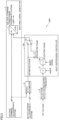
motor 2 using a dq coordinate system can be employed. The current flowing throughmotor 2 is indicated by current information output fromcurrent detector 6.Switching signal generator 7 calculates a voltage command in the dq coordinate system through the vector control using the current information output fromcurrent detector 6. Then, switchingsignal generator 7 uses the designated phase to convert the voltage command calculated in the dq coordinate system into that in a three-phase coordinate system. Thus, an AC voltage corresponding to the designated phase is output frominverter circuit 5. - It should be noted that switching
signal generator 7 may generate the switching signal using V/f constant control for outputting a voltage proportional to an operation frequency ofmotor 2, or using direct torque control for controlling magnetic flux and torque ofmotor 2. - As described above, the DC voltage rectified by
rectifier circuit 3 includes the pulsation component that pulsates at the frequency six times as large as the voltage frequency ofAC power supply 1. This pulsation component is not smoothed byDC link capacitor 4. Therefore, a beat component resulting from the pulsation component can be superimposed on the current flowing throughmotor 2. When a difference is small between a frequency (hereinafter, referred to as "pulsation frequency") of the pulsation component and a frequency (hereinafter, referred to as "operation frequency ofmotor 2") of the AC voltage output frominverter circuit 5, a large beat component is likely to occur. As a configuration for suppressing the beat component,power conversion device 100 according to the present embodiment further includes aspeed estimator 8, apulsation detector 9, and abeat suppression controller 10. -
Speed estimator 8 estimates rotation speed and magnetic pole position of a rotor ofmotor 2 using the current information output fromcurrent detector 6 and the voltage command calculated by switchingsignal generator 7.Speed estimator 8 estimates rotation speed and magnetic pole position of the rotor ofmotor 2 using a known estimation method. As the estimation method, a method of calculating it in accordance with a speed electromotive force ofmotor 2 is generally employed. For example, a method such as an arctangent method or an adaptive flux observer method can be employed.Speed estimator 8 outputs the estimated magnetic pole position, i.e., estimated phase, to beatsuppression controller 10. -
Pulsation detector 9 detects the pulsation frequency in accordance with a DC voltage applied acrossDC link capacitor 4, and outputs the detection result to beatsuppression controller 10. SinceDC link capacitor 4 has a small capacitance as described above, the DC voltage applied acrossDC link capacitor 4 pulsates at the pulsation frequency about six times as large as the voltage frequency ofAC power supply 1.Pulsation detector 9 detects this pulsation frequency. For example,pulsation detector 9 detects the pulsation frequency by allowing the value of the DC voltage to pass through a band pass filter. Alternatively,pulsation detector 9 may detect the pulsation frequency by subtracting, from the value of the original DC voltage, a result obtained by allowing the value of the DC voltage to pass through a notch filter. -
Beat suppression controller 10 outputs, to switchingsignal generator 7, an adjusted phase obtained by adjusting the estimated phase output fromspeed estimator 8 so as to suppress the beat component superimposed on the current flowing throughmotor 2.Switching signal generator 7 uses the adjusted phase as the designated phase. -
Fig. 2 is a diagram showing exemplary internal configurations of switchingsignal generator 7 and beatsuppression controller 10. As shown inFig. 2 , switchingsignal generator 7 includes aconverter 11.Converter 11 uses a designatedphase 8 to convert a voltage commands Vd*, Vq* in the dq coordinate system into voltage commands Vu*, Vv*, Vw* in the three-phase coordinate system in accordance with the following conversion formula.Switching signal generator 7 generates a switching signal for controllinginverter circuit 5 using voltage commands Vu*, Vv*, Vw*.
-
Beat suppression controller 10 includes anamplifier 12, anintegrator 13, and anadder 14.Amplifier 12 multiplies, by a gain K, the pulsation frequency output frompulsation detector 9. Gain K is determined in accordance with the voltage frequency ofAC power supply 1 and the magnitude of the DC voltage acrossDC link capacitor 4. Gain K may be a fixed value determined in advance. Alternatively, gain K may be a variable value determined in accordance with states ofAC power supply 1 andmotor 2. -
Integrator 13 outputs an integral value of the output ofamplifier 12. The integral value indicates a phase (hereinafter, referred to as "pulsation phase") of the pulsation component included in the DC voltage. -
Adder 14 outputs, as the adjusted phase, a phase obtained by adding the estimated phase output fromspeed estimator 8 and the pulsation phase output fromintegrator 13. Thus, beatsuppression controller 10 adjusts the estimated phase using the pulsation phase that is an integral value of the pulsation frequency. -
Fig. 3 is a diagram showing waveforms of a DC voltage, a current flowing through a motor, and a pulsation phase added to an estimated phase in a power conversion device including nobeat suppression controller 10.Fig. 4 is a diagram showing waveforms of the DC voltage, the current flowing through the motor, and the pulsation phase added to the estimated phase inpower conversion device 100 includingbeat suppression controller 10. In each ofFigs. 3 and4 , the vertical axis of the graph at the upper part represents the DC voltage, the vertical axis of the graph at the intermediate part represents current flowing throughmotor 2, and the vertical axis of the graph at the lower part represents the pulsation phase. The horizontal axis of each graph represents elapsed time. - As shown in
Fig. 3 , in the case of the power conversion device including nobeat suppression controller 10, the pulsation phase added to the estimated phase is zero. In this case, switchingsignal generator 7 converts the voltage command in the dq coordinate system into the voltage command in the three-phase coordinate system using the estimated phase. Therefore, the current flowing throughmotor 2 is influenced by the pulsation component included in the DC voltage, and therefore includes the beat component as shown in the intermediate part ofFig. 3 . In particular, when the pulsation frequency is close to the operation frequency ofmotor 2, a large beat component appears. - As shown in
Fig. 4 , in the case ofpower conversion device 100 includingbeat suppression controller 10, switchingsignal generator 7 converts the voltage command in the dq coordinate system into the voltage command in the three-phase coordinate system using the adjusted phase obtained by adding the pulsation phase shown in the lower part to the estimated phase. Thus, the influence of the pulsation component included in the DC voltage is canceled in the AC voltage output frominverter circuit 5. Therefore, as shown in the intermediate part, no beat component appears in the current flowing throughmotor 2. - Thus, according to
power conversion device 100 of the first embodiment, the estimated phase of the rotor ofmotor 2 is estimated based on the current flowing throughmotor 2. Therefore, no position sensor is required to detect the position of the rotor ofmotor 2, unlike the technology described inPTL 1. Further, the adjusted phase is generated by adjusting the estimated phase so as to suppress the beat component superimposed on the current flowing throughmotor 2. Moreover,inverter circuit 5 is controlled to output, frominverter circuit 5, the AC voltage corresponding to the adjusted phase. Thus, the beat component is suppressed. In view of the above, the beat component superimposed on the current flowing throughmotor 2 can be suppressed without increasing cost. - Further, the technology disclosed in
PTL 1 requires phase information of a voltage in the dq coordinate system. The phase information is calculated, for example, from a d-axis voltage Vd and a q-axis voltage Vq using an arctangent function (Arctan). However, the calculation of the arctangent function involves a large computational load, requires a high-performance microcomputer, and leads to increased cost. However, inpower conversion device 100 according to the first embodiment, the computation load is reduced, thus suppressing increased cost for the microcomputer. -
Fig. 5 is a diagram showing a portion of a configuration of a power conversion device according to a second embodiment. As shown inFig. 5 , apower conversion device 100A according to the second embodiment is different frompower conversion device 100 according to the first embodiment in that abeat suppression controller 10A is provided instead ofbeat suppression controller 10. -
Beat suppression controller 10A is different frombeat suppression controller 10 in thatbeat suppression controller 10A includes anintegrator 13A instead ofintegrator 13 and includes aswitch 15. As withintegrator 13,integrator 13A integrates an output ofamplifier 12 so as to output an integrated value (i.e., pulsation phase).Integrator 13A resets the integral value to zero in response to input of a reset signal. -
Switch 15 switches between a first mode and a second mode, the first mode being a mode in which the adjusted phase is output to switchingsignal generator 7, the second mode being a mode in which the estimated phase is output to switchingsignal generator 7.Switch 15 switches from the second mode to the first mode in response to a predetermined operation condition being satisfied, and switches from the first mode to the second mode in response to the operation condition being not satisfied. - The operation condition is, for example, a condition that motor 2 is not undergoing acceleration/deceleration. Alternatively, the operation condition may be a condition that the magnitude (amplitude) of the pulsation included in the DC voltage across
DC link capacitor 4 is equal to or more than a reference value. Alternatively, the operation condition may include a plurality of conditions. When the operation condition includes such a plurality of conditions, it may be determined that the operation condition is satisfied when all of the plurality of conditions are satisfied, or it may be determined that the operation condition is satisfied when at least one of the plurality of conditions is satisfied. -
Beat suppression controller 10A inputs, tointegrator 13A, a reset signal for resetting the pulsation phase to zero, before switching from the second mode to the first mode byswitch 15. Specifically, beatsuppression controller 10A inputs the reset signal tointegrator 13A while the second mode is selected byswitch 15. -
Fig. 6 is a flowchart showing a flow of a beat suppression control process inpower conversion device 100A according to the second embodiment.Steps S 1 to S6 shown inFig. 6 are repeatedly performed. - In step S1, beat
suppression controller 10A calculates the pulsation phase by integrating the value obtained by multiplying the pulsation frequency by gain K. Next, in step S2, beatsuppression controller 10A adds the pulsation phase to the estimated phase, thereby generating the adjusted phase. - Next, in step S3, switch 15 determines whether or not the operation condition is satisfied. When the operation condition is satisfied (YES in step S3),
switch 15 selects the first mode and outputs the adjusted phase to switching signal generator 7 (step S4). After step S4,power conversion device 100A ends the beat suppression control process. - When the operation condition is not satisfied (YES in step S3),
beat suppression controller 10A inputs the reset signal tointegrator 13A (step S5).Switch 15 outputs the estimated phase to switching signal generator 7 (step S6). After step S6,power conversion device 100A ends the beat suppression control process. - When
motor 2 is undergoing acceleration/deceleration, the output value ofspeed estimator 8 is not stable. Therefore, when switchingsignal generator 7 performs the conversion using the adjusted phase, the effect of suppressing the beat component may not be sufficiently exhibited or diverging may be resulted in the control. Since the operation condition includes the condition that motor 2 is not undergoing acceleration/deceleration, the estimated phase is output to switchingsignal generator 7 whenmotor 2 is undergoing acceleration/deceleration. As a result, diverging in the control can be prevented. - When the pulsation component included in the DC voltage is small, the beat component is less likely to be superimposed on the current flowing through
motor 2, so that it is not necessary to suppress the beat component using the adjusted phase. Therefore, since the operation condition includes the condition that the magnitude of the pulsation included in the DC voltage acrossDC link capacitor 4 is equal to or more than the reference value, the suppression of the beat component using the adjusted phase is not performed when the pulsation component included in the DC voltage is small. - When the value of the phase input to switching
signal generator 7 is greatly changed upon switching from the second mode to the first mode, loss of synchronization may occur inmotor 2. The loss of synchronization is such a phenomenon that motor 2 cannot follow a pulse signal and stops rotation. - When the reset signal is input to
integrator 13A in step S5 as described above, the pulsation phase output fromintegrator 13A is reset to zero in the second mode. That is, the pulsation phase is reset to zero before switching from the second mode to the first mode. Therefore, when switching from the second mode to the first mode, an amount of change in the value of the phase input to switchingsignal generator 7 is suppressed. Thus, when switching from the second mode to the first mode, occurrence of the loss of synchronization inmotor 2 is suppressed, with the result that the beat suppressing effect is gradually exhibited. -
Fig. 7 is a schematic diagram showing anair conditioner 400 according to a third embodiment.Air conditioner 400 includes arefrigeration cycle apparatus 300 and ablower 401.Refrigeration cycle apparatus 300 includes arefrigerant compressing apparatus 200, acondenser 301, anexpansion valve 302, and anevaporator 303.Refrigerant compressing apparatus 200 has acompressor 201 andpower conversion device 100 described above. - As shown in
Fig. 7 ,compressor 201 andcondenser 301 are connected together by a tube. Similarly,condenser 301 andexpansion valve 302 are connected together by a tube,expansion valve 302 andevaporator 303 are connected together by a tube, andevaporator 303 andcompressor 201 are connected together by a tube. Thus, refrigerant circulates throughcompressor 201,condenser 301,expansion valve 302, andevaporator 303. -
Motor 2 shown inFig. 7 is provided incompressor 201 ofair conditioner 400, and is subject to variable speed control bypower conversion device 100 in order to compress refrigerant gas into high-pressure gas. Inrefrigeration cycle apparatus 300, processes of evaporation, compression, condensation, and expansion of the refrigerant are repeatedly performed. Further, the refrigerant is changed from liquid to gas and is further changed from gas to liquid, thereby performing heat exchange between the refrigerant and outside air. Therefore,air conditioner 400 is constructed by combiningrefrigeration cycle apparatus 300 withblower 401 configured to circulate the outside air. - An air conditioner in recent years is required to attain not only comfortability but also high efficiency due to tightened regulation for energy saving. Moreover, a demand for air conditioners is being increased in emerging countries. Therefore, it is important to provide an inexpensive air conditioner that uses a power conversion device for variable speed control of a motor. Since
power conversion device 100 includes inexpensive small-capacitanceDC link capacitor 4, these requirements can be satisfied. - When the beat component appears in the current flowing through
motor 2 while the operation frequency ofmotor 2 and the pulsation frequency of the DC voltage are close to each other, vibration and noise may be generated fromcompressor 201 or the tube connected tocompressor 201. As a result, comfortability of the user is compromised. Further, since the pulsation is superimposed on a work performed bymotor 2, efficiency of compression of the refrigerant gas is also decreased. Moreover, when an operation is performed while avoiding the operation frequency at which the beat component is generated, an optimum operation of the refrigeration cycle apparatus cannot be performed, thus resulting in decreased cycle efficiency. However, by usingpower conversion device 100 includingbeat suppression controller 10, occurrence of the beat component is suppressed. As a result, these problems are solved. - As described above,
air conditioner 400 includespower conversion device 100 including small-capacitanceDC link capacitor 4 and beatsuppression controller 10. Thus,inexpensive air conditioner 400 allowing for comfortability and high efficiency is provided. It should be noted thatair conditioner 400 may includepower conversion device 100A instead ofpower conversion device 100. Also in this case,inexpensive air conditioner 400 allowing for comfortability and high efficiency is provided. - In the description above,
air conditioner 400 has been described as an example to which each ofpower conversion devices power conversion devices power conversion devices - The embodiments disclosed herein are illustrative and non-restrictive in any respect. The scope of the present disclosure is defined by the terms of the claims, rather than the embodiments described above, and is intended to include any modifications within the scope and meaning equivalent to the terms of the claims.
- 1: AC power supply; 2: motor; 3: rectifier circuit; 4: DC link capacitor; 5: inverter circuit; 6: current detector; 7: switching signal generator; 8: speed estimator; 9: pulsation detector; 10, 10A: beat suppression controller; 11: converter; 12: amplifier; 13, 13A: integrator; 14: adder; 15: switch; 100, 100A: power conversion device; 200: refrigerant compressing apparatus; 201: compressor; 300: refrigeration cycle apparatus; 301: condenser; 302: expansion valve; 303: evaporator; 400: air conditioner; 401: blower.
Claims (5)
- A power conversion device comprising:a rectifier circuit configured to rectify an AC voltage to a DC voltage;an inverter circuit configured to convert, into an AC voltage, the DC voltage rectified by the rectifier circuit and output the converted AC voltage to a motor;a DC link capacitor connected between the rectifier circuit and the inverter circuit;a generator configured to generate a signal for controlling the inverter circuit to output, from the inverter circuit, an AC voltage corresponding to a designated phase;an estimator configured to estimate a first phase of a rotor of the motor based on a current flowing through the motor; anda beat suppression controller configured to output a second phase to the generator as the designated phase so as to suppress a beat component superimposed on the current flowing through the motor, the second phase being obtained by adjusting the first phase.
- The power conversion device according to claim 1, further comprising a detector configured to detect a pulsation frequency of the rectified DC voltage, wherein
the beat suppression controller adjusts the first phase using an integral value of the pulsation frequency. - The power conversion device according to claim 1 or 2, wherein the beat suppression controller includes a switch configured to switch between a first mode and a second mode, the first mode being a mode in which the second phase is output to the generator as the designated phase, the second mode being a mode in which the first phase is output to the generator as the designated phase.
- The power conversion device according to claim 2, whereinthe beat suppression controller includes a switch configured to switch between a first mode and a second mode, the first mode being a mode in which the second phase is output to the generator as the designated phase, the second mode being a mode in which the first phase is output to the generator as the designated phase, andthe beat suppression controller is configured to reset the integral value to zero before the switch makes switching from the second mode to the first mode.
- The power conversion device according to any one of claims 1 to 4, wherein the power conversion device is applied to an air conditioner.
Applications Claiming Priority (1)
| Application Number | Priority Date | Filing Date | Title |
|---|---|---|---|
| PCT/JP2021/001079 WO2022153448A1 (en) | 2021-01-14 | 2021-01-14 | Power conversion device |
Publications (3)
| Publication Number | Publication Date |
|---|---|
| EP4280445A1 true EP4280445A1 (en) | 2023-11-22 |
| EP4280445A4 EP4280445A4 (en) | 2024-03-06 |
| EP4280445B1 EP4280445B1 (en) | 2025-06-04 |
Family
ID=82448095
Family Applications (1)
| Application Number | Title | Priority Date | Filing Date |
|---|---|---|---|
| EP21919342.2A Active EP4280445B1 (en) | 2021-01-14 | 2021-01-14 | Power conversion device |
Country Status (5)
| Country | Link |
|---|---|
| US (1) | US12323068B2 (en) |
| EP (1) | EP4280445B1 (en) |
| JP (1) | JP7588661B2 (en) |
| CN (1) | CN116802982A (en) |
| WO (1) | WO2022153448A1 (en) |
Families Citing this family (4)
| Publication number | Priority date | Publication date | Assignee | Title |
|---|---|---|---|---|
| WO2023073870A1 (en) * | 2021-10-28 | 2023-05-04 | 三菱電機株式会社 | Power conversion device, motor driving device, and refrigeration-cycle application instrument |
| US20250141340A1 (en) * | 2021-10-28 | 2025-05-01 | Mitsubishi Electric Corporation | Power converting apparatus, motor drive unit, and refrigeration cycle-incorporating apparatus |
| AU2023266955B2 (en) * | 2022-05-11 | 2025-09-04 | Shenzhen JISU Technology Co., Ltd | Portable fan |
| CN115395851B (en) * | 2022-09-21 | 2023-06-13 | 哈尔滨工业大学 | Linear Modulation Region Extension Method for Permanent Magnet Synchronous Motor Drive System without Electrolytic Capacitor |
Family Cites Families (17)
| Publication number | Priority date | Publication date | Assignee | Title |
|---|---|---|---|---|
| US5959430A (en) | 1997-03-07 | 1999-09-28 | Kabushiki Kaisha Toshiba | Power conversion system |
| JP3277138B2 (en) | 1997-03-07 | 2002-04-22 | 株式会社東芝 | Power converter |
| JP3586078B2 (en) | 1997-09-08 | 2004-11-10 | 株式会社東芝 | Power converter |
| JP4010313B2 (en) * | 1997-10-31 | 2007-11-21 | 株式会社日立製作所 | Electric car drive device |
| CN101647186B (en) | 2007-04-27 | 2012-10-17 | 三菱电机株式会社 | Power conversion system |
| WO2008146381A1 (en) * | 2007-05-31 | 2008-12-04 | Mitsubishi Electric Corporation | Power converter |
| JP5304937B2 (en) | 2011-09-30 | 2013-10-02 | ダイキン工業株式会社 | Power converter |
| US9160271B2 (en) | 2012-01-18 | 2015-10-13 | Mitsubishi Electric Corporation | Power conversion device |
| JP6614825B2 (en) * | 2015-06-30 | 2019-12-04 | 日立ジョンソンコントロールズ空調株式会社 | Power conversion device, motor drive device, refrigeration device |
| JP2017046430A (en) * | 2015-08-26 | 2017-03-02 | ジョンソンコントロールズ ヒタチ エア コンディショニング テクノロジー(ホンコン)リミテッド | Motor controller, fluid machinery, air conditioner, and program |
| JP6195003B1 (en) | 2016-09-30 | 2017-09-13 | ダイキン工業株式会社 | Inverter device |
| JP6369517B2 (en) | 2016-09-30 | 2018-08-08 | ダイキン工業株式会社 | Control device for power converter |
| JP6629893B2 (en) * | 2018-02-05 | 2020-01-15 | ファナック株式会社 | Motor drive device for estimating stray capacitance |
| JP6863935B2 (en) * | 2018-07-31 | 2021-04-21 | ファナック株式会社 | Motor drive with DC link capacitor discharge circuit |
| DE112020001414T5 (en) * | 2019-04-23 | 2021-12-23 | Hitachi Astemo, Ltd. | Power conversion device and automotive system containing it |
| WO2022091884A1 (en) * | 2020-10-26 | 2022-05-05 | ファナック株式会社 | Converter having wiring state detection unit and motor drive device |
| US20250062679A1 (en) * | 2021-12-27 | 2025-02-20 | Mitsubishi Electric Corporation | Power conversion apparatus and air conditioner |
-
2021
- 2021-01-14 EP EP21919342.2A patent/EP4280445B1/en active Active
- 2021-01-14 US US18/255,269 patent/US12323068B2/en active Active
- 2021-01-14 WO PCT/JP2021/001079 patent/WO2022153448A1/en not_active Ceased
- 2021-01-14 CN CN202180086950.9A patent/CN116802982A/en active Pending
- 2021-01-14 JP JP2022574959A patent/JP7588661B2/en active Active
Also Published As
| Publication number | Publication date |
|---|---|
| WO2022153448A1 (en) | 2022-07-21 |
| US20240007010A1 (en) | 2024-01-04 |
| EP4280445B1 (en) | 2025-06-04 |
| US12323068B2 (en) | 2025-06-03 |
| JPWO2022153448A1 (en) | 2022-07-21 |
| CN116802982A (en) | 2023-09-22 |
| JP7588661B2 (en) | 2024-11-22 |
| EP4280445A4 (en) | 2024-03-06 |
Similar Documents
| Publication | Publication Date | Title |
|---|---|---|
| US12323068B2 (en) | Power conversion device | |
| CN106559026B (en) | A control method, control device and inverter air conditioner for a motor drive system | |
| AU2009309187B9 (en) | Power conversion device | |
| EP2667501B1 (en) | Power conversion apparatus | |
| JP5119222B2 (en) | Converter device, motor driving module, and refrigeration device | |
| CN106505527A (en) | Motor drive protection device, over-voltage protection method and transducer air conditioning | |
| KR102000060B1 (en) | Apparatus for correcting offset of current sensor | |
| US20190097559A1 (en) | Power conversion device, motor drive device, and refrigerator using same | |
| US20240372498A1 (en) | Power converter, motor drive device, and refrigeration cycle application apparatus | |
| CN103563243A (en) | Inverter Control | |
| US10270380B2 (en) | Power converting apparatus and heat pump device | |
| JP3586078B2 (en) | Power converter | |
| WO2023073870A1 (en) | Power conversion device, motor driving device, and refrigeration-cycle application instrument | |
| JP6806272B1 (en) | Motor demagnetization diagnostic device and motor control device demagnetization diagnostic method | |
| US20250219559A1 (en) | Power conversion apparatus, motor drive unit, and refrigeration cycle application apparatus | |
| US20250023497A1 (en) | Power conversion apparatus, motor drive device, and refrigeration cycle application device | |
| CN111934533B (en) | Voltage-multiplying rectification PFC circuit, control method thereof, storage medium and variable-frequency air conditioner | |
| US20250062679A1 (en) | Power conversion apparatus and air conditioner | |
| US20250219564A1 (en) | Motor drive device and refrigeration cycle apparatus | |
| JP5741000B2 (en) | Power converter | |
| JP2016127650A (en) | Power conversion device | |
| US20240396486A1 (en) | Power conversion apparatus, motor drive apparatus, and refrigeration cycle application apparatus | |
| JP7330401B2 (en) | Power conversion device, motor drive device and refrigeration cycle application equipment | |
| US20240405710A1 (en) | Power converter, motor drive apparatus, and refrigeration cycle applied apparatus | |
| JP6578657B2 (en) | Power converter |
Legal Events
| Date | Code | Title | Description |
|---|---|---|---|
| STAA | Information on the status of an ep patent application or granted ep patent |
Free format text: STATUS: THE INTERNATIONAL PUBLICATION HAS BEEN MADE |
|
| PUAI | Public reference made under article 153(3) epc to a published international application that has entered the european phase |
Free format text: ORIGINAL CODE: 0009012 |
|
| STAA | Information on the status of an ep patent application or granted ep patent |
Free format text: STATUS: REQUEST FOR EXAMINATION WAS MADE |
|
| 17P | Request for examination filed |
Effective date: 20230707 |
|
| AK | Designated contracting states |
Kind code of ref document: A1 Designated state(s): AL AT BE BG CH CY CZ DE DK EE ES FI FR GB GR HR HU IE IS IT LI LT LU LV MC MK MT NL NO PL PT RO RS SE SI SK SM TR |
|
| REG | Reference to a national code |
Ref country code: DE Ref legal event code: R079 Free format text: PREVIOUS MAIN CLASS: H02M0007480000 Ipc: H02P0029500000 Ref country code: DE Ref legal event code: R079 Ref document number: 602021031961 Country of ref document: DE Free format text: PREVIOUS MAIN CLASS: H02M0007480000 Ipc: H02P0029500000 |
|
| A4 | Supplementary search report drawn up and despatched |
Effective date: 20240202 |
|
| RIC1 | Information provided on ipc code assigned before grant |
Ipc: H02M 5/458 20060101ALI20240129BHEP Ipc: H02P 25/03 20160101ALI20240129BHEP Ipc: H02P 21/18 20160101ALI20240129BHEP Ipc: H02M 1/14 20060101ALI20240129BHEP Ipc: H02M 1/12 20060101ALI20240129BHEP Ipc: H02M 7/48 20070101ALI20240129BHEP Ipc: H02P 29/50 20160101AFI20240129BHEP |
|
| DAV | Request for validation of the european patent (deleted) | ||
| DAX | Request for extension of the european patent (deleted) | ||
| GRAP | Despatch of communication of intention to grant a patent |
Free format text: ORIGINAL CODE: EPIDOSNIGR1 |
|
| STAA | Information on the status of an ep patent application or granted ep patent |
Free format text: STATUS: GRANT OF PATENT IS INTENDED |
|
| RIC1 | Information provided on ipc code assigned before grant |
Ipc: H02M 7/5387 20070101ALI20241219BHEP Ipc: H02M 1/14 20060101ALI20241219BHEP Ipc: H02P 21/18 20160101ALI20241219BHEP Ipc: H02P 25/03 20160101ALI20241219BHEP Ipc: H02M 5/458 20060101ALI20241219BHEP Ipc: H02P 29/50 20160101AFI20241219BHEP |
|
| INTG | Intention to grant announced |
Effective date: 20250109 |
|
| GRAS | Grant fee paid |
Free format text: ORIGINAL CODE: EPIDOSNIGR3 |
|
| GRAA | (expected) grant |
Free format text: ORIGINAL CODE: 0009210 |
|
| STAA | Information on the status of an ep patent application or granted ep patent |
Free format text: STATUS: THE PATENT HAS BEEN GRANTED |
|
| AK | Designated contracting states |
Kind code of ref document: B1 Designated state(s): AL AT BE BG CH CY CZ DE DK EE ES FI FR GB GR HR HU IE IS IT LI LT LU LV MC MK MT NL NO PL PT RO RS SE SI SK SM TR |
|
| REG | Reference to a national code |
Ref country code: GB Ref legal event code: FG4D |
|
| REG | Reference to a national code |
Ref country code: CH Ref legal event code: EP |
|
| REG | Reference to a national code |
Ref country code: DE Ref legal event code: R096 Ref document number: 602021031961 Country of ref document: DE |
|
| REG | Reference to a national code |
Ref country code: IE Ref legal event code: FG4D |
|
| REG | Reference to a national code |
Ref country code: NL Ref legal event code: MP Effective date: 20250604 |
|
| PG25 | Lapsed in a contracting state [announced via postgrant information from national office to epo] |
Ref country code: FI Free format text: LAPSE BECAUSE OF FAILURE TO SUBMIT A TRANSLATION OF THE DESCRIPTION OR TO PAY THE FEE WITHIN THE PRESCRIBED TIME-LIMIT Effective date: 20250604 Ref country code: ES Free format text: LAPSE BECAUSE OF FAILURE TO SUBMIT A TRANSLATION OF THE DESCRIPTION OR TO PAY THE FEE WITHIN THE PRESCRIBED TIME-LIMIT Effective date: 20250604 |
|
| REG | Reference to a national code |
Ref country code: LT Ref legal event code: MG9D |
|
| PG25 | Lapsed in a contracting state [announced via postgrant information from national office to epo] |
Ref country code: NO Free format text: LAPSE BECAUSE OF FAILURE TO SUBMIT A TRANSLATION OF THE DESCRIPTION OR TO PAY THE FEE WITHIN THE PRESCRIBED TIME-LIMIT Effective date: 20250904 Ref country code: GR Free format text: LAPSE BECAUSE OF FAILURE TO SUBMIT A TRANSLATION OF THE DESCRIPTION OR TO PAY THE FEE WITHIN THE PRESCRIBED TIME-LIMIT Effective date: 20250905 |
|
| PG25 | Lapsed in a contracting state [announced via postgrant information from national office to epo] |
Ref country code: PL Free format text: LAPSE BECAUSE OF FAILURE TO SUBMIT A TRANSLATION OF THE DESCRIPTION OR TO PAY THE FEE WITHIN THE PRESCRIBED TIME-LIMIT Effective date: 20250604 |
|
| PG25 | Lapsed in a contracting state [announced via postgrant information from national office to epo] |
Ref country code: BG Free format text: LAPSE BECAUSE OF FAILURE TO SUBMIT A TRANSLATION OF THE DESCRIPTION OR TO PAY THE FEE WITHIN THE PRESCRIBED TIME-LIMIT Effective date: 20250604 |
|
| PG25 | Lapsed in a contracting state [announced via postgrant information from national office to epo] |
Ref country code: HR Free format text: LAPSE BECAUSE OF FAILURE TO SUBMIT A TRANSLATION OF THE DESCRIPTION OR TO PAY THE FEE WITHIN THE PRESCRIBED TIME-LIMIT Effective date: 20250604 |
|
| PG25 | Lapsed in a contracting state [announced via postgrant information from national office to epo] |
Ref country code: RS Free format text: LAPSE BECAUSE OF FAILURE TO SUBMIT A TRANSLATION OF THE DESCRIPTION OR TO PAY THE FEE WITHIN THE PRESCRIBED TIME-LIMIT Effective date: 20250904 |
|
| PG25 | Lapsed in a contracting state [announced via postgrant information from national office to epo] |
Ref country code: LV Free format text: LAPSE BECAUSE OF FAILURE TO SUBMIT A TRANSLATION OF THE DESCRIPTION OR TO PAY THE FEE WITHIN THE PRESCRIBED TIME-LIMIT Effective date: 20250604 |
|
| PG25 | Lapsed in a contracting state [announced via postgrant information from national office to epo] |
Ref country code: NL Free format text: LAPSE BECAUSE OF FAILURE TO SUBMIT A TRANSLATION OF THE DESCRIPTION OR TO PAY THE FEE WITHIN THE PRESCRIBED TIME-LIMIT Effective date: 20250604 |
|
| PG25 | Lapsed in a contracting state [announced via postgrant information from national office to epo] |
Ref country code: PT Free format text: LAPSE BECAUSE OF FAILURE TO SUBMIT A TRANSLATION OF THE DESCRIPTION OR TO PAY THE FEE WITHIN THE PRESCRIBED TIME-LIMIT Effective date: 20251006 |
|
| REG | Reference to a national code |
Ref country code: AT Ref legal event code: MK05 Ref document number: 1801373 Country of ref document: AT Kind code of ref document: T Effective date: 20250604 |
|
| PG25 | Lapsed in a contracting state [announced via postgrant information from national office to epo] |
Ref country code: IS Free format text: LAPSE BECAUSE OF FAILURE TO SUBMIT A TRANSLATION OF THE DESCRIPTION OR TO PAY THE FEE WITHIN THE PRESCRIBED TIME-LIMIT Effective date: 20251004 |
|
| PGFP | Annual fee paid to national office [announced via postgrant information from national office to epo] |
Ref country code: GB Payment date: 20251127 Year of fee payment: 6 |
|
| PG25 | Lapsed in a contracting state [announced via postgrant information from national office to epo] |
Ref country code: SM Free format text: LAPSE BECAUSE OF FAILURE TO SUBMIT A TRANSLATION OF THE DESCRIPTION OR TO PAY THE FEE WITHIN THE PRESCRIBED TIME-LIMIT Effective date: 20250604 Ref country code: AT Free format text: LAPSE BECAUSE OF FAILURE TO SUBMIT A TRANSLATION OF THE DESCRIPTION OR TO PAY THE FEE WITHIN THE PRESCRIBED TIME-LIMIT Effective date: 20250604 |
|
| PG25 | Lapsed in a contracting state [announced via postgrant information from national office to epo] |
Ref country code: CZ Free format text: LAPSE BECAUSE OF FAILURE TO SUBMIT A TRANSLATION OF THE DESCRIPTION OR TO PAY THE FEE WITHIN THE PRESCRIBED TIME-LIMIT Effective date: 20250604 |
|
| PG25 | Lapsed in a contracting state [announced via postgrant information from national office to epo] |
Ref country code: EE Free format text: LAPSE BECAUSE OF FAILURE TO SUBMIT A TRANSLATION OF THE DESCRIPTION OR TO PAY THE FEE WITHIN THE PRESCRIBED TIME-LIMIT Effective date: 20250604 |
|
| PG25 | Lapsed in a contracting state [announced via postgrant information from national office to epo] |
Ref country code: SK Free format text: LAPSE BECAUSE OF FAILURE TO SUBMIT A TRANSLATION OF THE DESCRIPTION OR TO PAY THE FEE WITHIN THE PRESCRIBED TIME-LIMIT Effective date: 20250604 |
|
| PG25 | Lapsed in a contracting state [announced via postgrant information from national office to epo] |
Ref country code: IT Free format text: LAPSE BECAUSE OF FAILURE TO SUBMIT A TRANSLATION OF THE DESCRIPTION OR TO PAY THE FEE WITHIN THE PRESCRIBED TIME-LIMIT Effective date: 20250604 |
|
| REG | Reference to a national code |
Ref country code: DE Ref legal event code: R097 Ref document number: 602021031961 Country of ref document: DE |
|
| PLBE | No opposition filed within time limit |
Free format text: ORIGINAL CODE: 0009261 |
|
| STAA | Information on the status of an ep patent application or granted ep patent |
Free format text: STATUS: NO OPPOSITION FILED WITHIN TIME LIMIT |
|
| PG25 | Lapsed in a contracting state [announced via postgrant information from national office to epo] |
Ref country code: DK Free format text: LAPSE BECAUSE OF FAILURE TO SUBMIT A TRANSLATION OF THE DESCRIPTION OR TO PAY THE FEE WITHIN THE PRESCRIBED TIME-LIMIT Effective date: 20250604 |
|
| PGFP | Annual fee paid to national office [announced via postgrant information from national office to epo] |
Ref country code: DE Payment date: 20251203 Year of fee payment: 6 |
|
| REG | Reference to a national code |
Ref country code: CH Ref legal event code: L10 Free format text: ST27 STATUS EVENT CODE: U-0-0-L10-L00 (AS PROVIDED BY THE NATIONAL OFFICE) Effective date: 20260416 |