EP4280420A2 - Portable charging station - Google Patents
Portable charging station Download PDFInfo
- Publication number
- EP4280420A2 EP4280420A2 EP23174066.3A EP23174066A EP4280420A2 EP 4280420 A2 EP4280420 A2 EP 4280420A2 EP 23174066 A EP23174066 A EP 23174066A EP 4280420 A2 EP4280420 A2 EP 4280420A2
- Authority
- EP
- European Patent Office
- Prior art keywords
- battery pack
- power tool
- charging station
- housing
- door
- Prior art date
- Legal status (The legal status is an assumption and is not a legal conclusion. Google has not performed a legal analysis and makes no representation as to the accuracy of the status listed.)
- Pending
Links
Images

































Classifications
-
- H—ELECTRICITY
- H02—GENERATION; CONVERSION OR DISTRIBUTION OF ELECTRIC POWER
- H02J—ELECTRIC POWER NETWORKS; CIRCUIT ARRANGEMENTS OR SYSTEMS FOR SUPPLYING OR DISTRIBUTING ELECTRIC POWER; SYSTEMS FOR STORING ELECTRIC ENERGY
- H02J7/00—Circuit arrangements for charging or discharging batteries or for supplying loads from batteries
- H02J7/70—Circuit arrangements for charging or discharging batteries or for supplying loads from batteries characterised by the mechanical construction
-
- H—ELECTRICITY
- H02—GENERATION; CONVERSION OR DISTRIBUTION OF ELECTRIC POWER
- H02J—ELECTRIC POWER NETWORKS; CIRCUIT ARRANGEMENTS OR SYSTEMS FOR SUPPLYING OR DISTRIBUTING ELECTRIC POWER; SYSTEMS FOR STORING ELECTRIC ENERGY
- H02J7/00—Circuit arrangements for charging or discharging batteries or for supplying loads from batteries
- H02J7/70—Circuit arrangements for charging or discharging batteries or for supplying loads from batteries characterised by the mechanical construction
- H02J7/731—Circuit arrangements for charging or discharging batteries or for supplying loads from batteries characterised by the mechanical construction specially adapted for holding portable devices containing batteries
-
- B—PERFORMING OPERATIONS; TRANSPORTING
- B25—HAND TOOLS; PORTABLE POWER-DRIVEN TOOLS; MANIPULATORS
- B25H—WORKSHOP EQUIPMENT, e.g. FOR MARKING-OUT WORK; STORAGE MEANS FOR WORKSHOPS
- B25H3/00—Storage means or arrangements for workshops facilitating access to, or handling of, work tools or instruments
- B25H3/02—Boxes
-
- H—ELECTRICITY
- H01—ELECTRIC ELEMENTS
- H01M—PROCESSES OR MEANS, e.g. BATTERIES, FOR THE DIRECT CONVERSION OF CHEMICAL ENERGY INTO ELECTRICAL ENERGY
- H01M10/00—Secondary cells; Manufacture thereof
- H01M10/42—Methods or arrangements for servicing or maintenance of secondary cells or secondary half-cells
- H01M10/46—Accumulators structurally combined with charging apparatus
-
- H—ELECTRICITY
- H02—GENERATION; CONVERSION OR DISTRIBUTION OF ELECTRIC POWER
- H02J—ELECTRIC POWER NETWORKS; CIRCUIT ARRANGEMENTS OR SYSTEMS FOR SUPPLYING OR DISTRIBUTING ELECTRIC POWER; SYSTEMS FOR STORING ELECTRIC ENERGY
- H02J7/00—Circuit arrangements for charging or discharging batteries or for supplying loads from batteries
- H02J7/50—Circuit arrangements for charging or discharging batteries or for supplying loads from batteries acting upon multiple batteries simultaneously or sequentially
-
- H—ELECTRICITY
- H02—GENERATION; CONVERSION OR DISTRIBUTION OF ELECTRIC POWER
- H02J—ELECTRIC POWER NETWORKS; CIRCUIT ARRANGEMENTS OR SYSTEMS FOR SUPPLYING OR DISTRIBUTING ELECTRIC POWER; SYSTEMS FOR STORING ELECTRIC ENERGY
- H02J7/00—Circuit arrangements for charging or discharging batteries or for supplying loads from batteries
- H02J7/70—Circuit arrangements for charging or discharging batteries or for supplying loads from batteries characterised by the mechanical construction
- H02J7/751—Circuit arrangements for charging or discharging batteries or for supplying loads from batteries characterised by the mechanical construction concerning the insertion or the connection of the batteries
-
- H—ELECTRICITY
- H01—ELECTRIC ELEMENTS
- H01M—PROCESSES OR MEANS, e.g. BATTERIES, FOR THE DIRECT CONVERSION OF CHEMICAL ENERGY INTO ELECTRICAL ENERGY
- H01M2220/00—Batteries for particular applications
- H01M2220/30—Batteries in portable systems, e.g. mobile phone, laptop
-
- H—ELECTRICITY
- H02—GENERATION; CONVERSION OR DISTRIBUTION OF ELECTRIC POWER
- H02J—ELECTRIC POWER NETWORKS; CIRCUIT ARRANGEMENTS OR SYSTEMS FOR SUPPLYING OR DISTRIBUTING ELECTRIC POWER; SYSTEMS FOR STORING ELECTRIC ENERGY
- H02J2105/00—Networks for supplying or distributing electric power characterised by their spatial reach or by the load
- H02J2105/40—Networks for supplying or distributing electric power characterised by their spatial reach or by the load characterised by the loads connecting to the networks or being supplied by the networks
- H02J2105/44—Portable electronic devices
-
- H—ELECTRICITY
- H02—GENERATION; CONVERSION OR DISTRIBUTION OF ELECTRIC POWER
- H02J—ELECTRIC POWER NETWORKS; CIRCUIT ARRANGEMENTS OR SYSTEMS FOR SUPPLYING OR DISTRIBUTING ELECTRIC POWER; SYSTEMS FOR STORING ELECTRIC ENERGY
- H02J2207/00—Details of circuit arrangements for charging or discharging batteries or supplying loads from batteries
- H02J2207/20—Charging or discharging characterised by the power electronics converter
Definitions
- the present disclosure relates generally to a charging enclosure including multiple battery packs, devices, and related methods.
- the present disclosure includes a portable charging station including a housing, a handle coupled to the housing and extending along a height axis of the portable charging station, a charging circuit disposed in the housing, a power tool battery pack interface electrically connected to the charging circuit, and a door including a hinge connected to the housing.
- the charging circuit includes a rechargeable battery.
- the power tool battery pack interface defines an insertion axis. The insertion axis extends along the height axis.
- the door is pivotable between an open position and a closed position. The door is intersected by the insertion axis in the closed position.
- the present disclosure includes a portable charging station including a housing, a handle coupled to the housing and extending along a height axis of the portable charging station, a charging circuit disposed in the housing, a power tool battery pack interface electrically connected to the charging circuit, and a door including a hinge pivotably connecting the door to the housing about a pivot axis extending along the height axis.
- the charging circuit includes a rechargeable battery. The door is opposite the handle.
- a portable charging station includes a housing at least partially defining a sealed internal cavity therein, a handle coupled to the housing and extending along a height axis of the portable charging station, a charging circuit disposed in the sealed internal cavity, an interface wall including a power tool battery pack interface, and a plurality of wheels rotatably coupled to the housing.
- the charging circuit includes a rechargeable battery.
- the interface wall cooperates with the housing to enclose the sealed internal cavity.
- the power tool battery pack interface is electrically connected to the charging circuit.
- the present disclosure includes a portable charging station comprising:
- the housing may include a cavity defined therein, the cavity surrounded by an edge of the housing, a plane coincident with the edge extends uninterrupted over the cavity.
- the power tool battery pack interface may be one of a plurality of power tool battery pack interfaces arranged in at least two rows, and each of the plurality of power tool battery pack interfaces may be electrically connected to the charging circuit and includes a respective insertion axis, each insertion axis extending along the height axis.
- the power tool battery pack interface may include a first port configured to receive a first power tool battery pack and a second port configured to receive a second power tool battery pack, the first port may be configured to deliver power having a different voltage than the second port, and the insertion axis may correspond to at least one of the first port and the second port.
- the charging station may further comprise a latch engageable with an edge of the door opposite the hinge to sealingly secure the door in the closed position.
- the door may include a plurality of non-powered power tool battery pack interfaces on a side of the door opposite the housing.
- the present disclosure includes a portable charging station comprising:
- the power tool battery pack interface may be one of a plurality of power tool battery pack interfaces arranged in at least two columns, and each column may include a plurality of the power tool battery pack interfaces.
- the first column may include a first power tool battery pack interface defining a first insertion axis
- the second column may include a second power tool battery pack interface defining a second insertion axis
- the first insertion axis may be oblique relative to the second insertion axis.
- the power tool battery pack interface may include a first port configured to receive a first power tool battery pack and a second port may be configured to receive a second power tool battery pack, and the first port may be configured to deliver power having a different voltage than the second port.
- the charging station may further comprise a plurality of doors opposite the handle, the plurality of doors including the door.
- the charging station may further comprise a latch engageable with an edge of the door opposite the hinge to sealingly secure the door to the housing.
- a portion of the door may be configured to receive a lock therethrough to lock the door to the housing.
- the charging station may further comprise
- the charging station may further comprise a plurality of vents defined in the housing.
- the charging circuit may further include an inverter electrically connected to the rechargeable battery.
- the present disclosure includes a portable charging station comprising:
- the interface wall may define a stepped surface opposite the wheels.
- the power tool battery pack interface may include a first port configured to receive a first power tool battery pack and a second port may be configured to receive a second power tool battery pack, and the first port may be configured to deliver power having a different voltage than the second port.
- the power tool battery pack interface may be one of a plurality of power tool battery pack interfaces arranged in at least two rows, and wherein each of the plurality of power tool battery pack interfaces may be electrically connected to the charging circuit.
- At least one of the rows may cooperate with the stepped surface to define a battery receiving trench.
- the cabinet charger 100 includes a housing 104 and a door 106 pivotably coupled to the housing 104.
- the illustrated housing 104 is surrounded by a support structure 108.
- the illustrated support structure 108 is composed of a plurality of tubular sections 112.
- the housing 104 defines a first side 116 and a second side 120 opposite the first side 116.
- a handle 122 is coupled to the first side 116.
- the handle 122 may be coupled to the support structure 108.
- the handle 122 defines a height axis 124.
- a plurality of wheels 128 is rotatably coupled to the first side 116. In some embodiments, the wheels 128 may instead be rotatably coupled to the support structure 108.
- the illustrated cabinet charger 100 includes one door 106.
- the cabinet charger 100 may include multiple doors 106.
- the doors 106 may both be positioned on the second side 120.
- the doors 106 may be positioned on lateral sides of the cabinet charger 100, with each door 106 positioned between the first and second sides 116, 120 ( FIGS. 57A-62C ).
- the door 106 is pivotable between an opened position and a closed position about hinges 132.
- the illustrated cabinet charger 100 includes two hinges 132.
- the cabinet charger 100 may include fewer or more hinges 132.
- the door 106 is secured in the closed position by a latch 136.
- the illustrated latch 136 is positioned near an edge of the door 106 opposite the hinges 132.
- the illustrated cabinet charger 100 includes one latch 136. In other embodiments, the cabinet charger 100 may include more than one latch 136.
- the housing 104 includes a first housing portion 140 and a second housing portion 144 coupled to the first housing portion 140.
- the first housing portion 140 may define a sealed internal cavity 148. As such, the first housing portion 140 is sealed to prevent debris (e.g., water, dirt, dust, etc.) from entering the sealed internal cavity 148.
- the first housing portion 140 supports a charging circuit 152.
- the charging circuit 152 includes a charger 156 and a core 160 electrically coupled to the charger 156.
- the illustrated core 160 is offset from the second housing portion 144 along the height axis 124.
- the illustrated charger 156 is positioned between the second housing portion 144 and the handle 122. In other embodiments, the charger 156 may be positioned near the core 160 and offset from the second housing portion 144 along the height axis 124.
- the second housing portion 144 is offset from the first housing portion 140 along the height axis 124.
- the second housing portion 144 and the door 106 together define an interface cavity 168.
- the interface cavity 168 includes a plurality of battery pack interfaces 164 oriented in a first cabinet interface configuration 166.
- the battery pack interfaces 164 are configured to receive power tool battery packs 172.
- Each of the battery pack interfaces 164 defines an insertion axis 176.
- the illustrated insertion axes 176 extend transverse to the height axis 124. In some embodiments, the insertion axes 176 may be perpendicular to the height axis 124. In other embodiments, the insertion axes 176 may extend in a plurality of different directions.
- the illustrated battery pack interfaces 164 are arranged in two columns 180. Each illustrated column 180 includes three battery pack interfaces 164.
- FIG. 1H illustrates the first cabinet interface configuration 166.
- the plurality of battery pack interfaces 164 includes a first battery pack interface 164a configured to receive a first battery pack 172a having a first voltage (e.g., 18V).
- the plurality of battery pack interfaces 164 further includes a second battery pack interface 164b configured to receive the first battery pack 172a and a second battery pack 172b having a second voltage different than the first voltage (e.g., 12V).
- the second battery pack interface 164b may be referred to as a combo port.
- the illustrated plurality of battery pack interfaces 164 includes five of the first battery pack interfaces 164a and one of the second battery pack interfaces 164b.
- the cabinet charger 100 further includes a charging port 200 configured to receive a charging cord (e.g., a USB cable).
- the illustrated charging port 200 is positioned between adjacent battery pack interfaces 164 in a direction transverse to the height axis 124.
- FIG. 1I illustrates a second cabinet interface configuration 186 of the cabinet charger 100.
- the battery pack interfaces 164 are arranged in two columns 180, with four battery pack interfaces 164 in each column 180.
- the columns 180 may include fewer or more battery pack interfaces 164.
- the illustrated columns 180 extend in directions extending along each other. In some embodiments, the columns 180 may extend in parallel directions. In other embodiments, the columns 180 may extend in intersecting directions.
- the handle 122 is a telescopic handle and includes two poles 184 and a grip portion 188 extending therebetween.
- the grip portion 188 extends in a direction oriented transversely relative to the height axis 124.
- the grip portion 188 may be made of a gripping material (e.g., rubber).
- FIG. 1J illustrates the charger 156 of the charging circuit 152.
- the charger 156 includes a circuit board and an inverter.
- the charger 156 is configured to receive AC power from a power source (e.g., an external power source via a charging cord).
- the charger 156 is then configured to convert the AC power to DC power (e.g., via the inverter), and then supply the DC power to the core 160 to charge the core 160.
- the illustrated charger 156 further includes a cooling fan 192 and a heatsink 196.
- the cooling fan 192 and the heatsink 196 are configured to dissipate heat generated by the charger 156 during operation.
- the cabinet charger 100 further includes a plurality of vents to allow cooling air to travel through the housing 104 to assist in dissipating heat generated by the charger 156 and other components of the cabinet charger 100 (e.g., the battery pack interfaces 164, the core 160, etc.).
- FIG. 1K illustrates the core 160 of the charging circuit 152.
- the core 160 is configured to receive DC power from the charger 156 and store the power.
- the core 160 is electrically connected to the battery pack interfaces 164.
- the core 160 is further configured to supply the DC power to the battery pack interfaces 164 to charge the battery packs 172.
- the core 160 is sized to store sufficient power, such that a user may transport the cabinet charger 100 to a location (e.g., a worksite) and charge the battery packs 172 during a period of time (e.g., a work day).
- FIG. 1L illustrates the door 106 in the opened position.
- the door 106 includes gaskets 204, which are configured to create a seal with the second housing portion 144.
- the gaskets 204 may be received in respective recesses in the door 106.
- the illustrated door 106 includes two gaskets 204. In other embodiments, the door 106 may include fewer or more gaskets 204. In yet other embodiments, the gaskets 204 may be positioned in the second housing portion 144 instead of the door 106.
- FIGS. 1M and 1N illustrate the latch 136 and a locking system 208 of the cabinet charger 100.
- the illustrated latch 136 includes a lever 212, an engaging portion 216 (e.g., a metal loop), and a receiving portion 220.
- the receiving portion 220 is formed as a recess in the door 106.
- the lever 212 is pivotable relative to the second housing portion 144 between a secured position and an unsecured position.
- the engaging portion 216 is pivotably coupled to the second housing portion 144 between an engaged position in which the engaging portion 216 is received in the receiving portion 220 and a disengaged position in which the engaging portion 216 is not received in the receiving portion 220.
- the latch 136 is in a latched position when the engaging portion 216 is in the engaged position, and the lever 212 is in the secured position.
- the latch 136 is in an unlatched position when the lever 212 is in the unsecured position.
- the locking system 208 includes two locking apertures 224 extending through the door 106 and the second housing portion 144, respectively.
- the locking system 208 further includes a lock 228 configured to be received in the locking apertures 224.
- the locking apertures 224 may receive a chain 232 (e.g., a metal chain, a cord, etc.).
- the lock 228 may be removably coupled to the chain 232.
- the illustrated locking system 208 is positioned on the same side of the door 106 as the latch 136. In other embodiments, the locking system 208 may be positioned on a different side of the door 106 as the latch 136.
- the housing 104 includes a stackable surface 236 on a top side 240 of the housing 104.
- the top side 240 is the side of the housing 104 opposite the wheels 128.
- the stackable surface 236 includes a plurality of stacking interfaces 244.
- the stacking interfaces 244 are configured to support components 248 (e.g., toolboxes, radios, shelves, etc.), which are securably coupled to the stacking interfaces 244.
- the stacking interfaces 244 may be referred to as non-powered power tool battery pack interfaces.
- the stacking interfaces 244 are shaped the same as the battery pack interfaces 164 to slidably receive the components 248. However, the stacking interfaces 244 do not receive power.
- the stacking interfaces 244 may be shaped to support a different connection (e.g., bayonet connection, etc.).
- the power cord is plugged into an external power source (e.g., a wall plug providing mains electricity).
- the power cord supplies AC power to the charger 156, which converts the AC power to DC power (e.g., via the inverter) and then supplies the DC power to the core 160 to charge the core 160.
- the power cord may be removed from the external power source.
- the cabinet charger 100 may then be moved to the work site (e.g., rolled via the wheels 128).
- the lock 228 may be removed from the locking apertures 224 and the latch 136 may be moved to the unlatched position.
- the door 106 may then be pivoted from the closed position to the opened position.
- Battery packs 172 may be secured to the battery pack interfaces 164 to charge the battery packs 172.
- the door 106 may then be pivoted to the closed position, the latch 136 may be moved to the latched position, and the lock 228 may be received in the locking apertures 224. After a period of time, the battery packs 172 will be charged.
- the lock 228 may be removed, the latch 126 may be moved to the unlatched position, and the door 106 may be moved to the opened position to access the charged battery packs 172.
- Components 248 may be removably coupled to the stackable surface 236 during any time.
- FIGS. 2A-2E illustrate different embodiments of the second battery pack interface 164b.
- the second battery pack interfaces 164b each include a first port 252 and a second port 256.
- the first port 252 is configured to slidably receive the first battery pack 172a along a first insertion axis 176a.
- the second port 256 is configured to receive the second battery pack 172b along a second insertion axis 176b.
- the first insertion axis 176a extends along the second insertion axis 176b.
- the first insertion axis 176a intersects the second insertion axis 176b.
- the first and second battery packs 172a, 172b are illustrated as being transposed and received on or in the respective ports 252, 256. However, the illustrated second battery pack interfaces 164b may only receive one battery pack 172a, 172b at a time.
- FIGS. 3A-3D illustrate another embodiment of a portable charging station or chest charger 1100, with terms similar to FIGS. 1A-2E labeled similarly plus a value of one thousand.
- the battery charger 1100 may include any combination of features, dimensions, or ranges of dimensions from the preceding or subsequent embodiments, but only features of the chest charger 1100 not yet discussed with respect to the previous embodiment are detailed below.
- the chest charger 1100 includes the door 1106 pivotably coupled to the housing 1104.
- the door 1106 and the second housing portion 1144 define the interface cavity 1168.
- the interface cavity 1168 includes the plurality of battery pack interfaces 1164 oriented in a first chest interface configuration 1166.
- the illustrated battery pack interfaces 1164 are arranged in two rows 1180.
- the illustrated rows 1180 each include four battery pack interfaces 1164.
- the insertion axis 1176 of each of the battery pack interfaces 1164 extends along the height axis 1124.
- the insertion axes 1176 may be parallel with the height axis 1124.
- the insertion axes 1176 intersect the door 1106 with the door 1106 in the closed position.
- the door 1106 includes the stackable surface on a top side 1240.
- the top side 1240 of the door 1106 is opposite the housing 1104 when the door 1106 is in the closed position.
- the second housing portion 1144 includes an edge 1242 opposite the first housing portion 1140.
- the edge 1242 surrounds the cavity 1168.
- the illustrated edge 1242 extends around a periphery of the second housing portion 1144.
- the edge 1242 may also extend along other portions of the second housing portion 1144.
- the illustrated edge 1242 is configured to contact the door 1106 with the door 1106 in the closed position.
- An edge plane is defined as coincident with the edge 1242.
- the edge plane extends uninterrupted over the cavity 1168. Said another way, the edge plane does not extend through any component (e.g., the battery pack interfaces 1164, the battery packs 1172, etc.) within the internal cavity 1168.
- the illustrated chest charger 1100 includes two latches 1136.
- the latches 1136 are positioned on the second side 1120 of the housing 1104.
- the hinges 132 are positioned opposite the latches 1136 on the first side 1116 of the housing 1104.
- the core 1160 is positioned between the charger 1156 and the handle 1122.
- the charger 1156 and the core 1160 are positioned in the sealed internal cavity 1148 of the first housing portion 1140.
- the charger 1156 and the core 1160 are offset from the battery pack interfaces 1164 along the height axis 1124.
- FIG. 4 illustrates another embodiment of a portable charging station or wheelbarrow charger 2100, with terms similar to FIGS. 1A-2E labeled similarly plus a value of two thousand.
- the wheelbarrow charger 2100 may include any combination of features, dimensions, or ranges of dimensions from the preceding or subsequent embodiments, but only features of the wheelbarrow charger 2100 not yet discussed with respect to the previous embodiments are detailed below.
- the wheelbarrow charger 2100 includes an interface wall 2260 coupled to a side of the housing 2104 opposite the wheels 2128.
- the interface wall 2260 is disposed above the housing 2104 along the height axis 2124.
- the interface wall 2260 defines a stepped surface 2264.
- the stepped surface 2264 includes a battery receiving trench 2268.
- the illustrated plurality of battery pack interfaces 2164 are arranged in two rows 2180, with four battery pack interfaces 2164 in each row 2180.
- One of the rows 2180 is positioned in the battery receiving trench 2268.
- the battery packs (not shown) are configured to be received in the battery receiving trench 2268.
- the insertion axis 2176 of each battery pack interface 2164 extends along the height axis 2124. In other embodiments, one or more of the battery pack interfaces 2164 may be oriented obliquely relative to the height axis 2124.
- the stepped surface 2264 may further include the stackable surface.
- the housing 2104 and the interface wall 2260 define the sealed internal cavity 2148.
- the charger 2156 and the core 2160 are positioned within the sealed internal cavity 2148.
- the wheelbarrow charger 2100 further includes a circuit board 2272 positioned in the sealed internal cavity 2148.
- the circuit board 2272 is offset from the core 2160 along the height axis 2124.
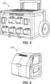
- FIGS. 5-8 illustrate a fourth, fifth, sixth, and seventh portable charging station 3100, 4100, 5100, 6100, respectively.
- the portable charging stations 3100, 4100, 5100, 6100 may include any combination of features, dimensions, or ranges of dimensions from the preceding or subsequent embodiments.
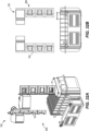
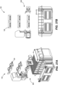
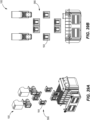
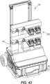
- FIGS. 9-43 illustrate additional embodiments of the configuration of battery pack interfaces 164 in the cabinet charger 100.
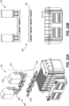
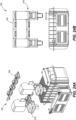
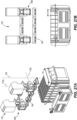
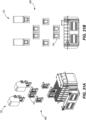
- FIGS. 9-43 illustrate third, fourth, fifth, sixth, seventh, eighth, ninth, tenth, eleventh, twelfth, thirteenth, fourteenth, fifteenth, sixteenth, seventeenth, eighteenth, nineteenth, twentieth, twenty-first, twenty-second, twenty-third, twenty-fourth, twenty-fifth, twenty-sixth, twenty-seventh, twenty-eighth, twenty-ninth, thirtieth, thirty-first, thirty-second, thirty-third, thirty-fourth, thirty-fifth, thirty-sixth, and thirty-seventh cabinet interface configurations 266, 276, 286, 296, 306, 316, 326, 336, 346, 356, 366, 376, 386, 396, 406, 416, 426, 436, 446, 456, 466, 476, 486, 496, 506, 516, 526, 536, 546,
- the eleventh cabinet interface configuration 346 includes a first row 182a and a second row 182b of battery pack interfaces 164.
- the second row 182b is positioned between the first row 182a and the first housing portion 140.
- the illustrated rows 182a, 182b each include four battery pack interfaces 164.
- the illustrated first row 182a includes two first battery pack interfaces 164a and two second battery pack interfaces 164b.
- the first battery pack interfaces 164a are positioned between the second battery pack interfaces 164b.
- the first and second insertion axes 176a, 176b of the second battery pack interfaces 164b extend obliquely relative to the height axis 124. Every insertion axis 176 of the battery pack interfaces 164 extends obliquely to the height axis 124.
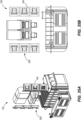
- the sixteenth cabinet interface configuration 396 of FIGS. 22A and 22B is similar to the eleventh cabinet interface configuration 346 but includes different second battery pack interfaces 164b.
- the first insertion axes 176a extend along the height axis 124 and the second insertion axes 176b extend obliquely relative to the first insertion axes 176a.
- the twenty-first cabinet interface configuration 446 of FIGS. 27A and 27B is also similar to the eleventh cabinet interface configuration 346 but includes different second battery pack interfaces 164b.
- the first insertion axes 176a extend along the height axis 124 and the second insertion axes 176b extend obliquely relative to the first insertion axes 176a.
- the illustrated second insertion axes 176b are perpendicular to the respective first insertion axes 176a.
- the twenty-fourth cabinet interface configuration 476 includes battery pack interfaces 164 oriented in three planes.
- a first plane is defined by two first battery pack interfaces 164a.
- the first plane extends between the first and second sides 116, 120 of the housing 104.
- Second and third planes are defined by respective second battery pack interfaces 164b.
- the first, second and third planes extend along the height axis 124.
- the second and third planes are oriented transverse to the first plane, respectively.
- the second and third planes are transversely oriented relative to each other.
- Two first battery pack interfaces 164a and one second battery pack interface 164b are oriented in each of the second and third planes.
- FIGS. 44A-77 illustrate additional embodiments of the interface cavity 168 and additional embodiments of the configuration of battery pack interfaces 164 in the cabinet charger 100.
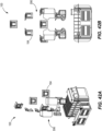
- FIGS. 44A-49C illustrate a first interface cavity 168a.
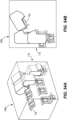
- FIGS. 50A-56B illustrate a second interface cavity 168b.
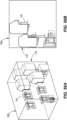
- FIGS. 57A-62C illustrate a third interface cavity 168c.
- the first, second, and third interface cavities 168a, 168b, 168c each define a first dimension 170 extending along the height axis 124, a second dimension 174 extending perpendicular to the first dimension 170, and a third dimension 178 extending perpendicular to the first and second dimensions 170, 174.
- FIGS. 44A-49C illustrate the first interface cavity 168a and thirty-eighth, thirty-ninth, fortieth, forty-first, forty-second, and fourth-third cabinet interface configurations 616, 626, 636, 646, 656, 666, respectively.
- the first dimension 170 is greater than the second and third dimensions 174, 178.
- the door is configured to extend along the first and second dimensions 170, 174 to enclose the first interface cavity 168a.
- FIGS. 50A-56B illustrate a second interface cavity 168b and forty-fourth, forty-fifth, forty-sixth, forty-seventh, forty-eighth, forty-ninth, and fiftieth cabinet interface configurations 676, 686, 696, 706, 716, 726, 736, respectively.
- the second dimension 174 is greater than the first and third dimensions 170, 178.
- the door is configured to extend along the first and second dimensions 170, 174 to enclose the second interface cavity 168b.
- FIGS. 57A-62C illustrate a third interface cavity 168c and fifty-first, fifty-second, fifty-third, fifty-fourth, fifty-fifth, and fifty-sixth cabinet interface configurations 746, 756, 766, 776, 786, 796, respectively.
- the second dimension 174 is greater than the first and third dimensions 170, 178.
- the third interface cavity 168c is configured to be enclosed by two doors. Each of the doors is configured to extend along the first and third dimensions 170, 178.
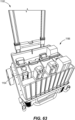
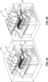
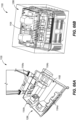
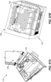
- FIGS. 63-77 illustrate additional embodiments of the configuration of battery pack interfaces 1164 in the chest charger 1100.
- FIGS. 63-77 illustrate a second, third, fourth, fifth, sixth, seventh, eighth, ninth, tenth, eleventh, twelfth, thirteenth, fourteenth, fifteenth, and sixteenth chest interface configurations 1186, 1266, 1276, 1286, 1296, 1306, 1316, 1326, 1336(10), 1346, 1356, 1366, 1376, 1386, 1396, respectively.
- the battery pack interfaces 1164 are positioned around a perimeter of the interface cavity 1168.
- the fifth chest interface configuration 1286 includes three first battery pack interfaces 1164a near the first side 1116 and the second side 1120 of the housing 1104, respectively.
- the fifth chest interface configuration 1286 further includes two second battery pack interfaces 1164b, one second battery pack interface 1164b near each of the remaining two sides of the interface cavity 1168.
- FIG. 78 illustrates a second wheelbarrow interface configuration 2186 for use in the wheelbarrow charger 2100.
- the second wheelbarrow interface configuration 2186 includes a first row 2180a and a second row 2180b.
- the first row 2180a is offset from the second row 2180b along the height axis 2124.
- the first row 2180a includes two second battery pack interfaces 2164b and two first battery pack interfaces 2164a therebetween.
- the second row 2180b includes four first battery pack interfaces 2164a. Every insertion axis 2176 of the battery pack interfaces 2164a, 2164b extends in direction along the height axis 2124.
Landscapes
- Engineering & Computer Science (AREA)
- Power Engineering (AREA)
- Manufacturing & Machinery (AREA)
- Chemical & Material Sciences (AREA)
- Chemical Kinetics & Catalysis (AREA)
- Electrochemistry (AREA)
- General Chemical & Material Sciences (AREA)
- Mechanical Engineering (AREA)
- Charge And Discharge Circuits For Batteries Or The Like (AREA)
Abstract
Description
- This application claims priority to
U.S. Provisional Patent Application No. 63/342,674, filed May 17, 2022 - The present disclosure relates generally to a charging enclosure including multiple battery packs, devices, and related methods.
- In one aspect, the present disclosure includes a portable charging station including a housing, a handle coupled to the housing and extending along a height axis of the portable charging station, a charging circuit disposed in the housing, a power tool battery pack interface electrically connected to the charging circuit, and a door including a hinge connected to the housing. The charging circuit includes a rechargeable battery. The power tool battery pack interface defines an insertion axis. The insertion axis extends along the height axis. The door is pivotable between an open position and a closed position. The door is intersected by the insertion axis in the closed position.
- In another aspect, the present disclosure includes a portable charging station including a housing, a handle coupled to the housing and extending along a height axis of the portable charging station, a charging circuit disposed in the housing, a power tool battery pack interface electrically connected to the charging circuit, and a door including a hinge pivotably connecting the door to the housing about a pivot axis extending along the height axis. The charging circuit includes a rechargeable battery. The door is opposite the handle.
- A portable charging station includes a housing at least partially defining a sealed internal cavity therein, a handle coupled to the housing and extending along a height axis of the portable charging station, a charging circuit disposed in the sealed internal cavity, an interface wall including a power tool battery pack interface, and a plurality of wheels rotatably coupled to the housing. The charging circuit includes a rechargeable battery. The interface wall cooperates with the housing to enclose the sealed internal cavity. The power tool battery pack interface is electrically connected to the charging circuit.
- In one aspect, the present disclosure includes a portable charging station comprising:
- a housing;
- a handle coupled to the housing and extending along a height axis of the portable charging station;
- a charging circuit disposed in the housing, the charging circuit including a rechargeable battery;
- a power tool battery pack interface electrically connected to the charging circuit, the power tool battery pack interface defining an insertion axis, the insertion axis extending along the height axis; and
- a door including a hinge connected to the housing, the door pivotable between an open position and a closed position, the door intersected by the insertion axis in the closed position.
- The housing may include a cavity defined therein, the cavity surrounded by an edge of the housing, a plane coincident with the edge extends uninterrupted over the cavity.
- The power tool battery pack interface may be one of a plurality of power tool battery pack interfaces arranged in at least two rows, and each of the plurality of power tool battery pack interfaces may be electrically connected to the charging circuit and includes a respective insertion axis, each insertion axis extending along the height axis.
- The power tool battery pack interface may include a first port configured to receive a first power tool battery pack and a second port configured to receive a second power tool battery pack, the first port may be configured to deliver power having a different voltage than the second port, and the insertion axis may correspond to at least one of the first port and the second port.
- The charging station may further comprise a latch engageable with an edge of the door opposite the hinge to sealingly secure the door in the closed position.
- The door may include a plurality of non-powered power tool battery pack interfaces on a side of the door opposite the housing.
- In one aspect, the present disclosure includes a portable charging station comprising:
- a housing;
- a handle coupled to the housing and extending along a height axis of the portable charging station;
- a charging circuit disposed in the housing, the charging circuit including a rechargeable battery;
- a power tool battery pack interface electrically connected to the charging circuit; and
- a door including a hinge pivotably connecting the door to the housing about a pivot axis extending along the height axis, the door opposite the handle.
- The power tool battery pack interface may be one of a plurality of power tool battery pack interfaces arranged in at least two columns, and each column may include a plurality of the power tool battery pack interfaces.
- The first column may include a first power tool battery pack interface defining a first insertion axis, the second column may include a second power tool battery pack interface defining a second insertion axis, and the first insertion axis may be oblique relative to the second insertion axis.
- The power tool battery pack interface may include a first port configured to receive a first power tool battery pack and a second port may be configured to receive a second power tool battery pack, and the first port may be configured to deliver power having a different voltage than the second port.
- The charging station may further comprise a plurality of doors opposite the handle, the plurality of doors including the door.
- The charging station may further comprise a latch engageable with an edge of the door opposite the hinge to sealingly secure the door to the housing.
- A portion of the door may be configured to receive a lock therethrough to lock the door to the housing.
- The charging station may further comprise
- a plurality of wheels rotatably coupled to the housing, and
- wherein the door may include a plurality of non-powered power tool battery pack interfaces on a side of the door opposite the plurality of wheels.
- The charging station may further comprise a plurality of vents defined in the housing.
- The charging circuit may further include an inverter electrically connected to the rechargeable battery.
- In one aspect, the present disclosure includes a portable charging station comprising:
- a housing at least partially defining a sealed internal cavity therein;
- a handle coupled to the housing and extending along a height axis of the portable charging station;
- a charging circuit disposed in the sealed internal cavity, the charging circuit including a rechargeable battery;
- an interface wall including a power tool battery pack interface, the interface wall cooperating with the housing to enclose the sealed internal cavity, the power tool battery pack interface electrically connected to the charging circuit; and
- a plurality of wheels rotatably coupled to the housing.
- The interface wall may define a stepped surface opposite the wheels.
- The power tool battery pack interface may include a first port configured to receive a first power tool battery pack and a second port may be configured to receive a second power tool battery pack, and the first port may be configured to deliver power having a different voltage than the second port.
- The power tool battery pack interface may be one of a plurality of power tool battery pack interfaces arranged in at least two rows, and wherein each of the plurality of power tool battery pack interfaces may be electrically connected to the charging circuit.
- At least one of the rows may cooperate with the stepped surface to define a battery receiving trench.
- Other aspects of the disclosure will become apparent by consideration of the detailed description and the accompanying drawings.
-
-
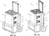
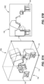
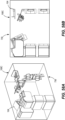
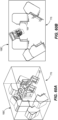
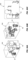
FIG. 1A is a perspective view of a portable charging station. -
FIG. 1B is another perspective view of the portable charging station ofFIG. 1A . -
FIG. 1C is another perspective view of the portable charging station ofFIG. 1A . -
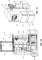
FIG. 1D is a perspective view of a cross-section of the portable charging station ofFIG. 1A . -
FIG. 1E is a perspective view of the portable charging station ofFIG. 1A with a door removed. -
FIG. 1F is another perspective view of the portable charging station ofFIG. 1A with the door removed. -
FIG. 1G is a perspective view of the portable charging station ofFIG. 1A with the housing and the door removed. -
FIG. 1H is a perspective view of a plurality of a battery pack interface configuration of the portable charging station ofFIG. 1A . -
FIG. 11 is a perspective view of the portable charging station ofFIG. 1A in a partially assembled state, with a transparent housing and another embodiment of a battery pack interface configuration. -
FIG. 1J is a perspective view of a charger of a charging circuit of the portable charging station ofFIG. 1A . -
FIG. 1K is a perspective view of a core of the charging circuit of the portable charging station ofFIG. 1A . -
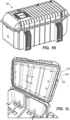
FIG. 1L is a perspective view of a door of the portable charging station ofFIG. 1A . -
FIG. 1M is a perspective view of a latch on the portable charging station ofFIG. 1A . -
FIG. 1N is a perspective view of a locking system on the portable charging station ofFIG. 1A . -
FIG. 2A is a perspective view of an embodiment of a battery pack interface. -
FIG. 2B is a perspective view of another embodiment of a battery pack interface. -
FIG. 2C is perspective view of another embodiment of a battery pack interface. -
FIG. 2D is a perspective view of another embodiment of a battery pack interface. -
FIG. 2E is a perspective view of another embodiment of a battery pack interface. -
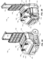
FIG. 3A is a perspective view of a portable charging station according to another embodiment. -
FIG. 3B is a perspective view of a cross-section of the portable charging station ofFIG. 3A . -
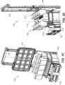
FIG. 3C is a perspective view of the portable charging station ofFIG. 3A with a housing removed. -
FIG. 3D is another perspective view of the portable charging station ofFIG. 3A with the housing removed. -
FIG. 4 is a perspective view of a partially assembled portable charging station according to another embodiment. -
FIG. 5 is a perspective view of a portable charging station according to another embodiment. -
FIG. 6 is a perspective view of a portable charging station according to another embodiment. -
FIG. 7 is a perspective view of a portable charging station according to another embodiment. -
FIG. 8 is a perspective view of a portable charging station according to another embodiment. -
FIG. 9 is a perspective view of another embodiment of a battery pack interface configuration for the portable charging station ofFIG. 1A . -
FIG. 10 is a perspective view of another embodiment of a battery pack interface configuration for the portable charging station ofFIG. 1A . -
FIG. 11 is a perspective view of another embodiment of a battery pack interface configuration for the portable charging station ofFIG. 1A . -
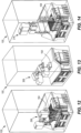
FIG. 12 is a perspective view of another embodiment of a battery pack interface configuration for the portable charging station ofFIG. 1A . -
FIG. 13 is a perspective view of another embodiment of a battery pack interface configuration for the portable charging station ofFIG. 1A . -
FIG. 14 is a perspective view of another embodiment of a battery pack interface configuration for the portable charging station ofFIG. 1A . -
FIG. 15A is a perspective view of another embodiment of a battery pack interface configuration for the portable charging station ofFIG. 1A . -
FIG. 15B is another perspective view of the battery pack interface configuration ofFIG. 15A . -
FIG. 16A is a perspective view of another embodiment of a battery pack interface configuration for the portable charging station ofFIG. 1A . -
FIG. 16B is another perspective view of the battery pack interface configuration ofFIG. 16A . -
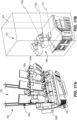
FIG. 17A is a perspective view of another embodiment of a battery pack interface configuration for the portable charging station ofFIG. 1A . -
FIG. 17B is another perspective view of the battery pack interface configuration ofFIG. 17 A . -
FIG. 18A is a perspective view of another embodiment of a battery pack interface configuration for the portable charging station ofFIG. 1A . -
FIG. 18B is another perspective view of the battery pack interface configuration ofFIG. 18A . -
FIG. 19A is a perspective view of another embodiment of a battery pack interface configuration for the portable charging station ofFIG. 1A . -
FIG. 19B is another perspective view of the battery pack interface configuration ofFIG. 19A . -
FIG. 20A is a perspective view of another embodiment of a battery pack interface configuration for the portable charging station ofFIG. 1A . -
FIG. 20B is another perspective view of the battery pack interface configuration ofFIG. 20A . -
FIG. 21A is a perspective view of another embodiment of a battery pack interface configuration for the portable charging station ofFIG. 1A . -
FIG. 21B is a front view of the battery pack interface configuration ofFIG. 21A . -
FIG. 22A is a perspective view of another embodiment of a battery pack interface configuration for the portable charging station ofFIG. 1A . -
FIG. 22B is a front view of the battery pack interface configuration ofFIG. 22A . -
FIG. 23A is a perspective view of another embodiment of a battery pack interface configuration for the portable charging station ofFIG. 1A . -
FIG. 23B is a front view of the battery pack interface configuration ofFIG. 23A . -
FIG. 24A is a perspective view of another embodiment of a battery pack interface configuration for the portable charging station ofFIG. 1A . -
FIG. 24B is a front view of the battery pack interface configuration ofFIG. 24A . -
FIG. 25A is a perspective view of another embodiment of a battery pack interface configuration for the portable charging station ofFIG. 1A . -
FIG. 25B is a front view of the battery pack interface configuration ofFIG. 25A . -
FIG. 26A is a perspective view of another embodiment of a battery pack interface configuration for the portable charging station ofFIG. 1A . -
FIG. 26B is a front view of the battery pack interface configuration ofFIG. 26A . -
FIG. 27A is a perspective view of another embodiment of a battery pack interface configuration for the portable charging station ofFIG. 1A . -
FIG. 27B is a front view of the battery pack interface configuration ofFIG. 27A . -
FIG. 28A is a perspective view of another embodiment of a battery pack interface configuration for the portable charging station ofFIG. 1A . -
FIG. 28B is a front view of the battery pack interface configuration ofFIG. 28A . -
FIG. 29A is a perspective view of another embodiment of a battery pack interface configuration for the portable charging station ofFIG. 1A . -
FIG. 29B is a front view of the battery pack interface configuration ofFIG. 29A . -
FIG. 30A is a perspective view of another embodiment of a battery pack interface configuration for the portable charging station ofFIG. 1A . -
FIG. 30B is another perspective view of the battery pack interface configuration ofFIG. 30A . -
FIG. 30C is a front view of the battery pack interface configuration ofFIG. 30A . -
FIG. 31A is a perspective view of another embodiment of a battery pack interface configuration for the portable charging station ofFIG. 1A . -
FIG. 31B is a front view of the battery pack interface configuration ofFIG. 31A . -
FIG. 32A is a perspective view of another embodiment of a battery pack interface configuration for the portable charging station ofFIG. 1A . -
FIG. 32B is a front view of the battery pack interface configuration ofFIG. 32A . -
FIG. 33A is a perspective view of another embodiment of a battery pack interface configuration for the portable charging station ofFIG. 1A . -
FIG. 33B is a front view of the battery pack interface configuration ofFIG. 33A . -
FIG. 34A is a perspective view of another embodiment of a battery pack interface configuration for the portable charging station ofFIG. 1A . -
FIG. 34B is a front view of the battery pack interface configuration ofFIG. 34A . -
FIG. 35A is a perspective view of another embodiment of a battery pack interface configuration for the portable charging station ofFIG. 1A . -
FIG. 35B is a front view of the battery pack interface configuration ofFIG. 35A . -
FIG. 36A is a perspective view of another embodiment of a battery pack interface configuration for the portable charging station ofFIG. 1A . -
FIG. 36B is a front view of the battery pack interface configuration ofFIG. 36A . -
FIG. 37A is a perspective view of another embodiment of a battery pack interface configuration for the portable charging station ofFIG. 1A . -
FIG. 37B is a front view of the battery pack interface configuration ofFIG. 37A . -
FIG. 38A is a perspective view of another embodiment of a battery pack interface configuration for the portable charging station ofFIG. 1A . -
FIG. 38B is a front view of the battery pack interface configuration ofFIG. 38A . -
FIG. 39A is a perspective view of another embodiment of a battery pack interface configuration for the portable charging station ofFIG. 1A . -
FIG. 39B is a front view of the battery pack interface configuration ofFIG. 39A . -
FIG. 40A is a perspective view of another embodiment of a battery pack interface configuration for the portable charging station ofFIG. 1A . -
FIG. 40B is a front view of the battery pack interface configuration ofFIG. 40A . -
FIG. 41A is a perspective view of another embodiment of a battery pack interface configuration for the portable charging station ofFIG. 1A . -
FIG. 41B is a front view of the battery pack interface configuration ofFIG. 41A . -
FIG. 42A is a perspective view of another embodiment of a battery pack interface configuration for the portable charging station ofFIG. 1A . -
FIG. 42B is a front view of the battery pack interface configuration ofFIG. 42A . -
FIG. 43 is a perspective view of another embodiment of a battery pack interface configuration for the portable charging station ofFIG. 1A . -
FIG. 44A is a perspective view of an interface cavity and another battery pack interface configuration for the portable charging station ofFIG. 1A . -
FIG. 44B is a front view of the interface cavity ofFIG. 44A . -
FIG. 44C is a side view of the interface cavity ofFIG. 44A . -
FIG. 45A is a perspective view of another interface cavity and another battery pack interface configuration for the portable charging station ofFIG. 1A . -
FIG. 45B is a front view of the interface cavity ofFIG. 45A . -
FIG. 45C is a side view of the interface cavity ofFIG. 45A . -
FIG. 46A is a perspective view of another interface cavity and another battery pack interface configuration for the portable charging station ofFIG. 1A . -
FIG. 46B is a front view of the interface cavity ofFIG. 46A . -
FIG. 46C is a side view of the interface cavity ofFIG. 46A . -
FIG. 47A is a perspective view of another interface cavity and another battery pack interface configuration for the portable charging station ofFIG. 1A . -
FIG. 47B is a front view of the interface cavity ofFIG. 47A . -
FIG. 47C is a side view of the interface cavity ofFIG. 47A . -
FIG. 48A is a perspective view of another interface cavity and another battery pack interface configuration for the portable charging station ofFIG. 1A . -
FIG. 48B is a side view of the interface cavity ofFIG. 48A . -
FIG. 49A is a perspective view of another interface cavity and another battery pack interface configuration for the portable charging station ofFIG. 1A . -
FIG. 49B is a front view of the interface cavity ofFIG. 49A . -
FIG. 49C is a side view of the interface cavity ofFIG. 49A . -
FIG. 50A is a perspective view of another interface cavity and another battery pack interface configuration for the portable charging station ofFIG. 1A . -
FIG. 50B is a front view of the interface cavity ofFIG. 50A . -
FIG. 50C is a side view of the interface cavity ofFIG. 50A . -
FIG. 51A is a perspective view of another interface cavity and a battery pack interface configuration for the portable charging station ofFIG. 1A . -
FIG. 51B is a front view of the interface cavity ofFIG. 51A . -
FIG. 52A is a perspective view of another interface cavity and a battery pack interface configuration for the portable charging station ofFIG. 1A . -
FIG. 52B is a side view of the interface cavity ofFIG. 52A . -
FIG. 53A is a perspective view of another interface cavity and a battery pack interface configuration for the portable charging station ofFIG. 1A . -
FIG. 53B is a side view of the interface cavity ofFIG. 53A . -
FIG. 54A is a perspective view of another interface cavity and a battery pack interface configuration for the portable charging station ofFIG. 1A . -
FIG. 54B is a side view of the interface cavity ofFIG. 54A . -
FIG. 55A is a perspective view of another interface cavity and a battery pack interface configuration for the portable charging station ofFIG. 1A . -
FIG. 55B is a front view of the interface cavity ofFIG. 55A . -
FIG. 55C is a side view of the interface cavity ofFIG. 55A . -
FIG. 56A is a perspective view of another interface cavity and a battery pack interface configuration for the portable charging station ofFIG. 1A . -
FIG. 56B is a side view of the interface cavity ofFIG. 56A . -
FIG. 57A is a perspective view of another interface cavity and a battery pack interface configuration for the portable charging station ofFIG. 1A . -
FIG. 57B is a front view of the interface cavity ofFIG. 57A . -
FIG. 58A is a perspective view of another interface cavity and a battery pack interface configuration for the portable charging station ofFIG. 1A . -
FIG. 58B is a front view of the interface cavity ofFIG. 58A . -
FIG. 59A is a perspective view of another interface cavity and a battery pack interface configuration for the portable charging station ofFIG. 1A . -
FIG. 59B is a front view of the interface cavity ofFIG. 59A . -
FIG. 59C is a side view of the interface cavity ofFIG. 59A . -
FIG. 60A is a perspective view of another interface cavity and a battery pack interface configuration for the portable charging station ofFIG. 1A . -
FIG. 60B is a front view of the interface cavity ofFIG. 60A . -
FIG. 61A is a perspective view of another interface cavity and a battery pack interface configuration for the portable charging station ofFIG. 1A . -
FIG. 61B is a front view of the interface cavity ofFIG. 61A . -
FIG. 62A is a perspective view of another interface cavity and a battery pack interface configuration for the portable charging station ofFIG. 1A . -
FIG. 62B is another perspective view of the interface cavity ofFIG. 62A . -
FIG. 62C is a front view of the interface cavity ofFIG. 62A . -
FIG. 63 is a perspective view of an embodiment of a battery pack interface configuration for the portable charging station ofFIG. 3A . -
FIG. 64 is a perspective view of another embodiment of a battery pack interface configuration for the portable charging station ofFIG. 3A . -
FIG. 65 is perspective view of another embodiment of a battery pack interface configuration for the portable charging station ofFIG. 3A . -
FIG. 66A is a perspective view of another embodiment of a battery pack interface configuration for the portable charging station ofFIG. 3A . -
FIG. 66B is another perspective view of the battery pack interface configuration ofFIG. 66A . -
FIG. 67A is a perspective view of another embodiment of a battery pack interface configuration for the portable charging station ofFIG. 3A . -
FIG. 67B is another perspective view of the battery pack interface configuration ofFIG. 67A . -
FIG. 68A is a perspective view of another embodiment of a battery pack interface configuration for the portable charging station ofFIG. 3A . -
FIG. 68B is another perspective view of the battery pack interface configuration ofFIG. 68A . -
FIG. 69A is a perspective view of another embodiment of a battery pack interface configuration for the portable charging station ofFIG. 3A . -
FIG. 69B is another perspective view of the battery pack interface configuration ofFIG. 69A . -
FIG. 70A is a perspective view of another embodiment of a battery pack interface configuration for the portable charging station ofFIG. 3A . -
FIG. 70B is a front view of the battery pack interface configuration ofFIG. 70A . -
FIG. 71A is a perspective view of another embodiment of a battery pack interface configuration for the portable charging station ofFIG. 3A . -
FIG. 71B is a front view of the battery pack interface configuration ofFIG. 71A . -
FIG. 72A is a perspective view of another embodiment of a battery pack interface configuration for the portable charging station ofFIG. 3A . -
FIG. 72B is a front view of the battery pack interface configuration ofFIG. 72A . -
FIG. 73A is a perspective view of another embodiment of a battery pack interface configuration for the portable charging station ofFIG. 3A . -
FIG. 73B is a front view of the battery pack interface configuration ofFIG. 73A . -
FIG. 74A is a perspective view of another embodiment of a battery pack interface configuration for the portable charging station ofFIG. 3A . -
FIG. 74B is a front view of the battery pack interface configuration ofFIG. 74A . -
FIG. 75 is a perspective view of another embodiment of a battery pack interface configuration for the portable charging station ofFIG. 3A . -
FIG. 76 is a perspective view of another embodiment of a battery pack interface configuration for the portable charging station ofFIG. 3A . -
FIG. 77 is a perspective view of another embodiment of a battery pack interface configuration for the portable charging station ofFIG. 3A . -
FIG. 78 is a perspective view of an embodiment of a battery pack interface configuration for the portable charging station ofFIG. 4 . - Before any embodiments of the disclosure are explained in detail, it is to be understood that the disclosure is not limited in its application to the details of construction and the arrangement of components set forth in the following description or illustrated in the drawings. The disclosure is capable of other embodiments and of being practiced or of being carried out in various ways. Also, it is to be understood that the phraseology and terminology used herein is for the purpose of description and should not be regarded as limiting.
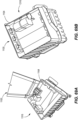
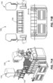
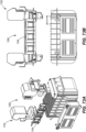
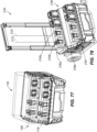
- With reference to
FIGS. 1A-1C , an embodiment of a portable charging station orcabinet charger 100 is shown. Thecabinet charger 100 includes ahousing 104 and adoor 106 pivotably coupled to thehousing 104. The illustratedhousing 104 is surrounded by asupport structure 108. The illustratedsupport structure 108 is composed of a plurality oftubular sections 112. Thehousing 104 defines afirst side 116 and asecond side 120 opposite thefirst side 116. Ahandle 122 is coupled to thefirst side 116. In some embodiments, thehandle 122 may be coupled to thesupport structure 108. Thehandle 122 defines aheight axis 124. A plurality ofwheels 128 is rotatably coupled to thefirst side 116. In some embodiments, thewheels 128 may instead be rotatably coupled to thesupport structure 108. - With continued reference to
FIGS. 1A-1C , thedoor 106 is pivotably coupled to thesecond side 120 thehousing 104. The illustratedcabinet charger 100 includes onedoor 106. In other embodiments, thecabinet charger 100 may includemultiple doors 106. In some embodiments with twodoors 106, thedoors 106 may both be positioned on thesecond side 120. In other embodiments with twodoors 106, thedoors 106 may be positioned on lateral sides of thecabinet charger 100, with eachdoor 106 positioned between the first andsecond sides 116, 120 (FIGS. 57A-62C ). Thedoor 106 is pivotable between an opened position and a closed position about hinges 132. The illustratedcabinet charger 100 includes two hinges 132. In other embodiments, thecabinet charger 100 may include fewer or more hinges 132. Thedoor 106 is secured in the closed position by alatch 136. The illustratedlatch 136 is positioned near an edge of thedoor 106 opposite thehinges 132. The illustratedcabinet charger 100 includes onelatch 136. In other embodiments, thecabinet charger 100 may include more than onelatch 136. - As illustrated in
FIGS. 1D-1G , thehousing 104 includes afirst housing portion 140 and asecond housing portion 144 coupled to thefirst housing portion 140. Thefirst housing portion 140 may define a sealedinternal cavity 148. As such, thefirst housing portion 140 is sealed to prevent debris (e.g., water, dirt, dust, etc.) from entering the sealedinternal cavity 148. Thefirst housing portion 140 supports a chargingcircuit 152. The chargingcircuit 152 includes acharger 156 and acore 160 electrically coupled to thecharger 156. The illustratedcore 160 is offset from thesecond housing portion 144 along theheight axis 124. The illustratedcharger 156 is positioned between thesecond housing portion 144 and thehandle 122. In other embodiments, thecharger 156 may be positioned near thecore 160 and offset from thesecond housing portion 144 along theheight axis 124. - With continued reference to
FIGS. 1D-1G , thesecond housing portion 144 is offset from thefirst housing portion 140 along theheight axis 124. Thesecond housing portion 144 and thedoor 106 together define aninterface cavity 168. Theinterface cavity 168 includes a plurality of battery pack interfaces 164 oriented in a firstcabinet interface configuration 166. The battery pack interfaces 164 are configured to receive power tool battery packs 172. Each of the battery pack interfaces 164 defines aninsertion axis 176. The illustratedinsertion axes 176 extend transverse to theheight axis 124. In some embodiments, the insertion axes 176 may be perpendicular to theheight axis 124. In other embodiments, the insertion axes 176 may extend in a plurality of different directions. The illustrated battery pack interfaces 164 are arranged in twocolumns 180. Each illustratedcolumn 180 includes three battery pack interfaces 164. -
FIG. 1H illustrates the firstcabinet interface configuration 166. The plurality of battery pack interfaces 164 includes a firstbattery pack interface 164a configured to receive afirst battery pack 172a having a first voltage (e.g., 18V). The plurality of battery pack interfaces 164 further includes a secondbattery pack interface 164b configured to receive thefirst battery pack 172a and asecond battery pack 172b having a second voltage different than the first voltage (e.g., 12V). The secondbattery pack interface 164b may be referred to as a combo port. The illustrated plurality of battery pack interfaces 164 includes five of the firstbattery pack interfaces 164a and one of the second battery pack interfaces 164b. In other embodiments, there may be fewer or more of the first and secondbattery pack interfaces second battery pack 172b. In other embodiments, the plurality of battery pack interfaces 164 may include a plurality of different battery pack interfaces, each configured to receive a battery pack having a different voltage. Thecabinet charger 100 further includes a chargingport 200 configured to receive a charging cord (e.g., a USB cable). The illustrated chargingport 200 is positioned between adjacent battery pack interfaces 164 in a direction transverse to theheight axis 124. -
FIG. 1I illustrates a secondcabinet interface configuration 186 of thecabinet charger 100. The battery pack interfaces 164 are arranged in twocolumns 180, with four battery pack interfaces 164 in eachcolumn 180. In other embodiments, thecolumns 180 may include fewer or more battery pack interfaces 164. The illustratedcolumns 180 extend in directions extending along each other. In some embodiments, thecolumns 180 may extend in parallel directions. In other embodiments, thecolumns 180 may extend in intersecting directions. - With reference to
FIGS. 1G , thehandle 122 is a telescopic handle and includes twopoles 184 and agrip portion 188 extending therebetween. Thegrip portion 188 extends in a direction oriented transversely relative to theheight axis 124. Thegrip portion 188 may be made of a gripping material (e.g., rubber). -
FIG. 1J illustrates thecharger 156 of the chargingcircuit 152. Thecharger 156 includes a circuit board and an inverter. Thecharger 156 is configured to receive AC power from a power source (e.g., an external power source via a charging cord). Thecharger 156 is then configured to convert the AC power to DC power (e.g., via the inverter), and then supply the DC power to thecore 160 to charge thecore 160. The illustratedcharger 156 further includes a coolingfan 192 and a heatsink 196. The coolingfan 192 and the heatsink 196 are configured to dissipate heat generated by thecharger 156 during operation. Thecabinet charger 100 further includes a plurality of vents to allow cooling air to travel through thehousing 104 to assist in dissipating heat generated by thecharger 156 and other components of the cabinet charger 100 (e.g., the battery pack interfaces 164, thecore 160, etc.). -
FIG. 1K illustrates thecore 160 of the chargingcircuit 152. Thecore 160 is configured to receive DC power from thecharger 156 and store the power. Thecore 160 is electrically connected to the battery pack interfaces 164. Thecore 160 is further configured to supply the DC power to the battery pack interfaces 164 to charge the battery packs 172. Thecore 160 is sized to store sufficient power, such that a user may transport thecabinet charger 100 to a location (e.g., a worksite) and charge the battery packs 172 during a period of time (e.g., a work day). -
FIG. 1L illustrates thedoor 106 in the opened position. Thedoor 106 includesgaskets 204, which are configured to create a seal with thesecond housing portion 144. Thegaskets 204 may be received in respective recesses in thedoor 106. The illustrateddoor 106 includes twogaskets 204. In other embodiments, thedoor 106 may include fewer ormore gaskets 204. In yet other embodiments, thegaskets 204 may be positioned in thesecond housing portion 144 instead of thedoor 106. -
FIGS. 1M and 1N illustrate thelatch 136 and alocking system 208 of thecabinet charger 100. The illustratedlatch 136 includes alever 212, an engaging portion 216 (e.g., a metal loop), and a receivingportion 220. The receivingportion 220 is formed as a recess in thedoor 106. Thelever 212 is pivotable relative to thesecond housing portion 144 between a secured position and an unsecured position. The engagingportion 216 is pivotably coupled to thesecond housing portion 144 between an engaged position in which the engagingportion 216 is received in the receivingportion 220 and a disengaged position in which the engagingportion 216 is not received in the receivingportion 220. Thelatch 136 is in a latched position when the engagingportion 216 is in the engaged position, and thelever 212 is in the secured position. Thelatch 136 is in an unlatched position when thelever 212 is in the unsecured position. Thelocking system 208 includes two lockingapertures 224 extending through thedoor 106 and thesecond housing portion 144, respectively. Thelocking system 208 further includes alock 228 configured to be received in the lockingapertures 224. In some embodiments, the lockingapertures 224 may receive a chain 232 (e.g., a metal chain, a cord, etc.). In these embodiments, thelock 228 may be removably coupled to thechain 232. The illustratedlocking system 208 is positioned on the same side of thedoor 106 as thelatch 136. In other embodiments, thelocking system 208 may be positioned on a different side of thedoor 106 as thelatch 136. - With reference to
FIG. 1N , thehousing 104 includes astackable surface 236 on atop side 240 of thehousing 104. Thetop side 240 is the side of thehousing 104 opposite thewheels 128. Thestackable surface 236 includes a plurality of stackinginterfaces 244. The stackinginterfaces 244 are configured to support components 248 (e.g., toolboxes, radios, shelves, etc.), which are securably coupled to the stacking interfaces 244. In some embodiments, the stackinginterfaces 244 may be referred to as non-powered power tool battery pack interfaces. In these embodiments, the stackinginterfaces 244 are shaped the same as the battery pack interfaces 164 to slidably receive thecomponents 248. However, the stackinginterfaces 244 do not receive power. In other embodiments, the stackinginterfaces 244 may be shaped to support a different connection (e.g., bayonet connection, etc.). - During operation, the power cord is plugged into an external power source (e.g., a wall plug providing mains electricity). The power cord supplies AC power to the
charger 156, which converts the AC power to DC power (e.g., via the inverter) and then supplies the DC power to thecore 160 to charge thecore 160. With thecore 160 sufficiently charged, the power cord may be removed from the external power source. Thecabinet charger 100 may then be moved to the work site (e.g., rolled via the wheels 128). Thelock 228 may be removed from the lockingapertures 224 and thelatch 136 may be moved to the unlatched position. Thedoor 106 may then be pivoted from the closed position to the opened position. Battery packs 172 may be secured to the battery pack interfaces 164 to charge the battery packs 172. Thedoor 106 may then be pivoted to the closed position, thelatch 136 may be moved to the latched position, and thelock 228 may be received in the lockingapertures 224. After a period of time, the battery packs 172 will be charged. Thelock 228 may be removed, the latch 126 may be moved to the unlatched position, and thedoor 106 may be moved to the opened position to access the charged battery packs 172.Components 248 may be removably coupled to thestackable surface 236 during any time. -
FIGS. 2A-2E illustrate different embodiments of the secondbattery pack interface 164b. The second battery pack interfaces 164b each include afirst port 252 and asecond port 256. With reference toFIG. 2A , thefirst port 252 is configured to slidably receive thefirst battery pack 172a along afirst insertion axis 176a. Thesecond port 256 is configured to receive thesecond battery pack 172b along asecond insertion axis 176b. In some embodiments, thefirst insertion axis 176a extends along thesecond insertion axis 176b. In other embodiments, thefirst insertion axis 176a intersects thesecond insertion axis 176b. The first andsecond battery packs respective ports battery pack interfaces 164b may only receive onebattery pack -
FIGS. 3A-3D illustrate another embodiment of a portable charging station orchest charger 1100, with terms similar toFIGS. 1A-2E labeled similarly plus a value of one thousand. Thebattery charger 1100 may include any combination of features, dimensions, or ranges of dimensions from the preceding or subsequent embodiments, but only features of thechest charger 1100 not yet discussed with respect to the previous embodiment are detailed below. - The
chest charger 1100 includes thedoor 1106 pivotably coupled to the housing 1104. Thedoor 1106 and thesecond housing portion 1144 define theinterface cavity 1168. Theinterface cavity 1168 includes the plurality ofbattery pack interfaces 1164 oriented in a first chest interface configuration 1166. The illustratedbattery pack interfaces 1164 are arranged in tworows 1180. The illustratedrows 1180 each include four battery pack interfaces 1164. Theinsertion axis 1176 of each of thebattery pack interfaces 1164 extends along theheight axis 1124. The insertion axes 1176 may be parallel with theheight axis 1124. The insertion axes 1176 intersect thedoor 1106 with thedoor 1106 in the closed position. - The
door 1106 includes the stackable surface on atop side 1240. Thetop side 1240 of thedoor 1106 is opposite the housing 1104 when thedoor 1106 is in the closed position. - The
second housing portion 1144 includes anedge 1242 opposite thefirst housing portion 1140. Theedge 1242 surrounds thecavity 1168. The illustratededge 1242 extends around a periphery of thesecond housing portion 1144. Theedge 1242 may also extend along other portions of thesecond housing portion 1144. The illustratededge 1242 is configured to contact thedoor 1106 with thedoor 1106 in the closed position. An edge plane is defined as coincident with theedge 1242. The edge plane extends uninterrupted over thecavity 1168. Said another way, the edge plane does not extend through any component (e.g., thebattery pack interfaces 1164, the battery packs 1172, etc.) within theinternal cavity 1168. - With reference to
FIGS. 3A and 3B , the illustratedchest charger 1100 includes twolatches 1136. Thelatches 1136 are positioned on thesecond side 1120 of the housing 1104. The hinges 132 are positioned opposite thelatches 1136 on thefirst side 1116 of the housing 1104. - With reference to
FIGS. 3C and 3D , thecore 1160 is positioned between thecharger 1156 and the handle 1122. Thecharger 1156 and thecore 1160 are positioned in the sealedinternal cavity 1148 of thefirst housing portion 1140. Thecharger 1156 and thecore 1160 are offset from thebattery pack interfaces 1164 along theheight axis 1124. -
FIG. 4 illustrates another embodiment of a portable charging station orwheelbarrow charger 2100, with terms similar toFIGS. 1A-2E labeled similarly plus a value of two thousand. Thewheelbarrow charger 2100 may include any combination of features, dimensions, or ranges of dimensions from the preceding or subsequent embodiments, but only features of thewheelbarrow charger 2100 not yet discussed with respect to the previous embodiments are detailed below. - The
wheelbarrow charger 2100 includes aninterface wall 2260 coupled to a side of thehousing 2104 opposite thewheels 2128. Theinterface wall 2260 is disposed above thehousing 2104 along theheight axis 2124. Theinterface wall 2260 defines a steppedsurface 2264. The steppedsurface 2264 includes abattery receiving trench 2268. The illustrated plurality ofbattery pack interfaces 2164 are arranged in tworows 2180, with fourbattery pack interfaces 2164 in eachrow 2180. One of therows 2180 is positioned in thebattery receiving trench 2268. The battery packs (not shown) are configured to be received in thebattery receiving trench 2268. Theinsertion axis 2176 of eachbattery pack interface 2164 extends along theheight axis 2124. In other embodiments, one or more of thebattery pack interfaces 2164 may be oriented obliquely relative to theheight axis 2124. The steppedsurface 2264 may further include the stackable surface. - The
housing 2104 and theinterface wall 2260 define the sealedinternal cavity 2148. Thecharger 2156 and thecore 2160 are positioned within the sealedinternal cavity 2148. Thewheelbarrow charger 2100 further includes acircuit board 2272 positioned in the sealedinternal cavity 2148. Thecircuit board 2272 is offset from thecore 2160 along theheight axis 2124. -
FIGS. 5-8 illustrate a fourth, fifth, sixth, and seventh portable chargingstation portable charging stations -
FIGS. 9-43 illustrate additional embodiments of the configuration of battery pack interfaces 164 in thecabinet charger 100.FIGS. 9-43 illustrate third, fourth, fifth, sixth, seventh, eighth, ninth, tenth, eleventh, twelfth, thirteenth, fourteenth, fifteenth, sixteenth, seventeenth, eighteenth, nineteenth, twentieth, twenty-first, twenty-second, twenty-third, twenty-fourth, twenty-fifth, twenty-sixth, twenty-seventh, twenty-eighth, twenty-ninth, thirtieth, thirty-first, thirty-second, thirty-third, thirty-fourth, thirty-fifth, thirty-sixth, and thirty-seventhcabinet interface configurations - As illustrated in
FIGS 17A and 17B , the eleventhcabinet interface configuration 346 includes afirst row 182a and asecond row 182b of battery pack interfaces 164. Thesecond row 182b is positioned between thefirst row 182a and thefirst housing portion 140. The illustratedrows first row 182a includes two firstbattery pack interfaces 164a and two second battery pack interfaces 164b. The firstbattery pack interfaces 164a are positioned between the second battery pack interfaces 164b. The first andsecond insertion axes height axis 124. Everyinsertion axis 176 of the battery pack interfaces 164 extends obliquely to theheight axis 124. - The sixteenth
cabinet interface configuration 396 ofFIGS. 22A and 22B is similar to the eleventhcabinet interface configuration 346 but includes different second battery pack interfaces 164b. Thefirst insertion axes 176a extend along theheight axis 124 and the second insertion axes 176b extend obliquely relative to thefirst insertion axes 176a. - The twenty-first
cabinet interface configuration 446 ofFIGS. 27A and 27B is also similar to the eleventhcabinet interface configuration 346 but includes different second battery pack interfaces 164b. Thefirst insertion axes 176a extend along theheight axis 124 and the second insertion axes 176b extend obliquely relative to thefirst insertion axes 176a. The illustrated second insertion axes 176b are perpendicular to the respectivefirst insertion axes 176a. - As illustrated in
FIGS. 30A-30C , the twenty-fourthcabinet interface configuration 476 includes battery pack interfaces 164 oriented in three planes. A first plane is defined by two firstbattery pack interfaces 164a. The first plane extends between the first andsecond sides housing 104. Second and third planes are defined by respective second battery pack interfaces 164b. The first, second and third planes extend along theheight axis 124. The second and third planes are oriented transverse to the first plane, respectively. The second and third planes are transversely oriented relative to each other. Two firstbattery pack interfaces 164a and one secondbattery pack interface 164b are oriented in each of the second and third planes. -
FIGS. 44A-77 illustrate additional embodiments of theinterface cavity 168 and additional embodiments of the configuration of battery pack interfaces 164 in thecabinet charger 100.FIGS. 44A-49C illustrate afirst interface cavity 168a.FIGS. 50A-56B illustrate asecond interface cavity 168b.FIGS. 57A-62C illustrate athird interface cavity 168c. The first, second, andthird interface cavities first dimension 170 extending along theheight axis 124, asecond dimension 174 extending perpendicular to thefirst dimension 170, and athird dimension 178 extending perpendicular to the first andsecond dimensions -
FIGS. 44A-49C illustrate thefirst interface cavity 168a and thirty-eighth, thirty-ninth, fortieth, forty-first, forty-second, and fourth-thirdcabinet interface configurations FIG. 44A , thefirst dimension 170 is greater than the second andthird dimensions second dimensions first interface cavity 168a. -
FIGS. 50A-56B illustrate asecond interface cavity 168b and forty-fourth, forty-fifth, forty-sixth, forty-seventh, forty-eighth, forty-ninth, and fiftiethcabinet interface configurations FIG. 50A , thesecond dimension 174 is greater than the first andthird dimensions second dimensions second interface cavity 168b. -
FIGS. 57A-62C illustrate athird interface cavity 168c and fifty-first, fifty-second, fifty-third, fifty-fourth, fifty-fifth, and fifty-sixthcabinet interface configurations FIG. 57A , thesecond dimension 174 is greater than the first andthird dimensions third interface cavity 168c is configured to be enclosed by two doors. Each of the doors is configured to extend along the first andthird dimensions -
FIGS. 63-77 illustrate additional embodiments of the configuration ofbattery pack interfaces 1164 in thechest charger 1100.FIGS. 63-77 illustrate a second, third, fourth, fifth, sixth, seventh, eighth, ninth, tenth, eleventh, twelfth, thirteenth, fourteenth, fifteenth, and sixteenthchest interface configurations - As illustrated in
FIGS. 66A and 66B , thebattery pack interfaces 1164 are positioned around a perimeter of theinterface cavity 1168. The fifthchest interface configuration 1286 includes three firstbattery pack interfaces 1164a near thefirst side 1116 and thesecond side 1120 of the housing 1104, respectively. The fifthchest interface configuration 1286 further includes two secondbattery pack interfaces 1164b, one secondbattery pack interface 1164b near each of the remaining two sides of theinterface cavity 1168. -
FIG. 78 illustrates a secondwheelbarrow interface configuration 2186 for use in thewheelbarrow charger 2100. The secondwheelbarrow interface configuration 2186 includes afirst row 2180a and asecond row 2180b. Thefirst row 2180a is offset from thesecond row 2180b along theheight axis 2124. Thefirst row 2180a includes two secondbattery pack interfaces 2164b and two firstbattery pack interfaces 2164a therebetween. Thesecond row 2180b includes four firstbattery pack interfaces 2164a. Everyinsertion axis 2176 of thebattery pack interfaces height axis 2124. - Although the disclosure has been described in detail with reference to certain preferred embodiments, variations and modifications exist within the scope and spirit of one or more independent aspects of the disclosure as illustrated and/or described. When used in this specification and claims, the terms "comprises" and "comprising" and variations thereof mean that the specified features, steps or integers are included. The terms are not to be interpreted to exclude the presence of other features, steps or components.
- Representative features are set out in the following clauses, which stand alone or may be combined, in any combination, with one or more features disclosed in the text and/or drawings of the specification.
- 1. A portable charging station comprising:
- a housing;
- a handle coupled to the housing and extending along a height axis of the portable charging station;
- a charging circuit disposed in the housing, the charging circuit including a rechargeable battery;
- a power tool battery pack interface electrically connected to the charging circuit, the power tool battery pack interface defining an insertion axis, the insertion axis extending along the height axis; and
- a door including a hinge connected to the housing, the door pivotable between an open position and a closed position, the door intersected by the insertion axis in the closed position.
- 2. The portable charging station of clause 1, wherein the housing includes a cavity defined therein, the cavity surrounded by an edge of the housing, a plane coincident with the edge extends uninterrupted over the cavity.
- 3. The portable charging station of clause 1, wherein
- the power tool battery pack interface is one of a plurality of power tool battery pack interfaces arranged in at least two rows, and
- each of the plurality of power tool battery pack interfaces is electrically connected to the charging circuit and includes a respective insertion axis, each insertion axis extending along the height axis.
- 4. The portable charging station of clause 1, wherein
- the power tool battery pack interface includes a first port configured to receive a first power tool battery pack and a second port configured to receive a second power tool battery pack,
- the first port is configured to deliver power having a different voltage than the second port, and
- the insertion axis corresponding to at least one of the first port and the second port.
- 5. The portable charging station of clause 1, further comprising a latch engageable with an edge of the door opposite the hinge to sealingly secure the door in the closed position.
- 6. The portable charging station of clause 1, wherein the door includes a plurality of non-powered power tool battery pack interfaces on a side of the door opposite the housing.
- 7. A portable charging station comprising:
- a housing;
- a handle coupled to the housing and extending along a height axis of the portable charging station;
- a charging circuit disposed in the housing, the charging circuit including a rechargeable battery;
- a power tool battery pack interface electrically connected to the charging circuit; and
- a door including a hinge pivotably connecting the door to the housing about a pivot axis extending along the height axis, the door opposite the handle.
- 8. The portable charging station of clause 7, wherein
- the power tool battery pack interface is one of a plurality of power tool battery pack interfaces arranged in at least two columns, and
- each column includes a plurality of the power tool battery pack interfaces.
- 9. The portable charging station of clause 8, wherein
- the first column includes a first power tool battery pack interface defining a first insertion axis,
- the second column includes a second power tool battery pack interface defining a second insertion axis, and
- the first insertion axis is oblique relative to the second insertion axis.
- 10. The portable charging station of clause 7, wherein
- the power tool battery pack interface includes a first port configured to receive a first power tool battery pack and a second port configured to receive a second power tool battery pack, and
- the first port is configured to deliver power having a different voltage than the second port.
- 11. The portable charging station of clause 7, further comprising a plurality of doors opposite the handle, the plurality of doors including the door.
- 12. The portable charging station of clause 7, further comprising a latch engageable with an edge of the door opposite the hinge to sealingly secure the door to the housing.
- 13. The portable charging station of clause 12, wherein a portion of the door is configured to receive a lock therethrough to lock the door to the housing.
- 14. The portable charging station of clause 7, further comprising
- a plurality of wheels rotatably coupled to the housing, and
- wherein the door includes a plurality of non-powered power tool battery pack interfaces on a side of the door opposite the plurality of wheels.
- 15. The portable charging station of clause 7, further comprising a plurality of vents defined in the housing.
- 16. The portable charging station of clause 7, wherein the charging circuit further includes an inverter electrically connected to the rechargeable battery.
- 17. A portable charging station comprising:
- a housing at least partially defining a sealed internal cavity therein;
- a handle coupled to the housing and extending along a height axis of the portable charging station;
- a charging circuit disposed in the sealed internal cavity, the charging circuit including a rechargeable battery;
- an interface wall including a power tool battery pack interface, the interface wall cooperating with the housing to enclose the sealed internal cavity, the power tool battery pack interface electrically connected to the charging circuit; and
- a plurality of wheels rotatably coupled to the housing.
- 18. The portable charging station of clause 17, wherein the interface wall defines a stepped surface opposite the wheels.
- 19. The portable charging station of clause 17, wherein
- the power tool battery pack interface includes a first port configured to receive a first power tool battery pack and a second port configured to receive a second power tool battery pack, and
- the first port is configured to deliver power having a different voltage than the second port.
- 20. The portable charging station of clause 17, wherein the power tool battery pack interface is one of a plurality of power tool battery pack interfaces arranged in at least two rows, and wherein each of the plurality of power tool battery pack interfaces is electrically connected to the charging circuit.
- 21. The portable charging station of clause 20, wherein at least one of the rows cooperates with the stepped surface to define a battery receiving trench.
Claims (14)
- A portable charging station comprising:a housing;a handle coupled to the housing and extending along a height axis of the portable charging station;a charging circuit disposed in the housing, the charging circuit including a rechargeable battery;a power tool battery pack interface electrically connected to the charging circuit, the power tool battery pack interface defining an insertion axis, the insertion axis extending along the height axis; anda door including a hinge connected to the housing, the door pivotable between an open position and a closed position, the door intersected by the insertion axis in the closed position.
- The portable charging station of claim 1, wherein the housing includes a cavity defined therein, the cavity surrounded by an edge of the housing, a plane coincident with the edge extends uninterrupted over the cavity.
- The portable charging station of claim 1 or 2, whereinthe power tool battery pack interface is one of a plurality of power tool battery pack interfaces arranged in at least two rows, andeach of the plurality of power tool battery pack interfaces is electrically connected to the charging circuit and includes a respective insertion axis, each insertion axis extending along the height axis.
- The portable charging station of claim 1, 2 or 3, whereinthe power tool battery pack interface includes a first port configured to receive a first power tool battery pack and a second port configured to receive a second power tool battery pack,the first port is configured to deliver power having a different voltage than the second port, andthe insertion axis corresponding to at least one of the first port and the second port.
- The portable charging station of any preceding claim, further comprising a latch engageable with an edge of the door opposite the hinge to sealingly secure the door in the closed position, and/or wherein the door includes a plurality of non-powered power tool battery pack interfaces on a side of the door opposite the housing.
- A portable charging station comprising:a housing;a handle coupled to the housing and extending along a height axis of the portable charging station;a charging circuit disposed in the housing, the charging circuit including a rechargeable battery;a power tool battery pack interface electrically connected to the charging circuit; anda door including a hinge pivotably connecting the door to the housing about a pivot axis extending along the height axis, the door opposite the handle.
- The portable charging station of claim 6, whereinthe power tool battery pack interface is one of a plurality of power tool battery pack interfaces arranged in at least two columns, andeach column includes a plurality of the power tool battery pack interfaces.
- The portable charging station of claim 7, whereinthe first column includes a first power tool battery pack interface defining a first insertion axis,the second column includes a second power tool battery pack interface defining a second insertion axis, andthe first insertion axis is oblique relative to the second insertion axis.
- The portable charging station of claim 6, 7 or 8, wherein:the power tool battery pack interface includes a first port configured to receive a first power tool battery pack and a second port configured to receive a second power tool battery pack, andthe first port is configured to deliver power having a different voltage than the second port, and/orfurther comprising a plurality of doors opposite the handle, the plurality of doors including the door, and/orfurther comprising a latch engageable with an edge of the door opposite the hinge to sealingly secure the door to the housing, preferably wherein a portion of the door is configured to receive a lock therethrough to lock the door to the housing.
- The portable charging station of any one of claims 6 to 9further comprising a plurality of wheels rotatably coupled to the housing, and wherein the door includes a plurality of non-powered power tool battery pack interfaces on a side of the door opposite the plurality of wheels, and/orfurther comprising a plurality of vents defined in the housing, and/orwherein the charging circuit further includes an inverter electrically connected to the rechargeable battery.
- A portable charging station comprising:a housing at least partially defining a sealed internal cavity therein;a handle coupled to the housing and extending along a height axis of the portable charging station;a charging circuit disposed in the sealed internal cavity, the charging circuit including a rechargeable battery;an interface wall including a power tool battery pack interface, the interface wall cooperating with the housing to enclose the sealed internal cavity, the power tool battery pack interface electrically connected to the charging circuit; anda plurality of wheels rotatably coupled to the housing.
- The portable charging station of claim 11, wherein the interface wall defines a stepped surface opposite the wheels.
- The portable charging station of claim 11 or 12, whereinthe power tool battery pack interface includes a first port configured to receive a first power tool battery pack and a second port configured to receive a second power tool battery pack, andthe first port is configured to deliver power having a different voltage than the second port.
- The portable charging station of claim 11, 12 or 13, wherein the power tool battery pack interface is one of a plurality of power tool battery pack interfaces arranged in at least two rows, and wherein each of the plurality of power tool battery pack interfaces is electrically connected to the charging circuit, preferably wherein at least one of the rows cooperates with the stepped surface to define a battery receiving trench.
Applications Claiming Priority (1)
| Application Number | Priority Date | Filing Date | Title |
|---|---|---|---|
| US202263342674P | 2022-05-17 | 2022-05-17 |
Publications (2)
| Publication Number | Publication Date |
|---|---|
| EP4280420A2 true EP4280420A2 (en) | 2023-11-22 |
| EP4280420A3 EP4280420A3 (en) | 2024-04-10 |
Family
ID=86387356
Family Applications (1)
| Application Number | Title | Priority Date | Filing Date |
|---|---|---|---|
| EP23174066.3A Pending EP4280420A3 (en) | 2022-05-17 | 2023-05-17 | Portable charging station |
Country Status (3)
| Country | Link |
|---|---|
| US (1) | US20230411975A1 (en) |
| EP (1) | EP4280420A3 (en) |
| CN (1) | CN220066926U (en) |
Families Citing this family (9)
| Publication number | Priority date | Publication date | Assignee | Title |
|---|---|---|---|---|
| CN110893610A (en) | 2016-05-02 | 2020-03-20 | 凯特尔塑料有限公司 | Utility module and coupling mechanism |
| WO2019028041A1 (en) | 2017-07-31 | 2019-02-07 | Milwaukee Electric Tool Corporation | STORAGE DEVICE SYSTEM |
| CN111867785A (en) | 2018-01-24 | 2020-10-30 | 米沃奇电动工具公司 | tool storage device |
| IL269564B2 (en) | 2019-09-23 | 2023-11-01 | Keter Home & Garden Products Ltd | Work donkey |
| EP4173111A4 (en) * | 2020-06-25 | 2024-07-24 | Milwaukee Electric Tool Corporation | CHARGE BALANCING FOR A MULTI-RACK POWER SUPPLY SYSTEM |
| CA202658S (en) * | 2020-10-08 | 2023-01-10 | Enel X S R L | Charging station |
| EP4342641A4 (en) * | 2021-06-29 | 2024-11-13 | Nanjing Chervon Industry Co., Ltd. | Toolbox system |
| US20240268042A1 (en) * | 2023-02-08 | 2024-08-08 | Assurant, Inc. | Container for electronic devices |
| JP1762936S (en) * | 2023-03-29 | 2024-02-05 | portable power supply |
Family Cites Families (8)
| Publication number | Priority date | Publication date | Assignee | Title |
|---|---|---|---|---|
| US9077053B2 (en) * | 2011-07-20 | 2015-07-07 | Milwaukee Electric Tool Corporation | Battery charger including multiple charging ports on surfaces forming an apex |
| US20130051104A1 (en) * | 2011-08-23 | 2013-02-28 | Hitachi Koki Co., Ltd. | Battery Adapter and Power Source Device Employing Same |
| US9539722B2 (en) * | 2012-12-19 | 2017-01-10 | Milwaukee Electric Tool Corporation | Tool storage devices |
| US10044197B2 (en) * | 2013-12-12 | 2018-08-07 | Milwaukee Electric Tool Corporation | Portable power supply and battery charger |
| EP3204995B1 (en) * | 2014-10-06 | 2022-01-05 | Black & Decker, Inc. | Portable power supply |
| CN108173319A (en) * | 2018-02-08 | 2018-06-15 | 安徽零度新能源科技有限公司 | Lithium battery group charging unit |
| KR102348315B1 (en) * | 2020-03-30 | 2022-01-10 | 주식회사 하늘항공 | Dron battery smart charge management apparatus |
| US20210408814A1 (en) * | 2020-06-30 | 2021-12-30 | Hsu Han | Intelligent charging equipment |
-
2023
- 2023-05-17 EP EP23174066.3A patent/EP4280420A3/en active Pending
- 2023-05-17 US US18/318,829 patent/US20230411975A1/en active Pending
- 2023-05-17 CN CN202321194446.3U patent/CN220066926U/en active Active
Also Published As
| Publication number | Publication date |
|---|---|
| EP4280420A3 (en) | 2024-04-10 |
| US20230411975A1 (en) | 2023-12-21 |
| CN220066926U (en) | 2023-11-21 |
Similar Documents
| Publication | Publication Date | Title |
|---|---|---|
| EP4280420A2 (en) | Portable charging station | |
| JP7423775B2 (en) | Battery pack and charger system | |
| KR102431932B1 (en) | MCC with Panel Unit | |
| CN1972004A (en) | Battery charger and assembly | |
| WO2023064385A1 (en) | Zero turn radius mower with removable battery packs | |
| CA2461029A1 (en) | Remote enclosure systems and methods of production thereof | |
| US20220376529A1 (en) | Work area charging | |
| CN103587563B (en) | Mobile computer trolley | |
| JPH087860A (en) | Battery case | |
| CN222868557U (en) | Portable power supply and socket panel assembly | |
| CN211478462U (en) | Online monitor for power grid impedance | |
| CN213845421U (en) | Portable portable power source of laser barrier removal device | |
| CN116534092A (en) | A quick disassembly structure and stair climbing machine | |
| CN116231205A (en) | Battery Packs and Consumers | |
| CN223743815U (en) | A stacked battery energy storage cabinet | |
| JP2005028463A (en) | Power tool storage case | |
| CN211033537U (en) | Construction standard part management device based on BIM | |
| JP2023024228A (en) | Safety device of power module applied to medium-high voltage system | |
| CN202684886U (en) | Portable tool storage vehicle | |
| CN218783378U (en) | Temporary distribution box for electric power engineering construction | |
| CN219959290U (en) | Plug-in lithium battery pack for household energy storage | |
| CN213991356U (en) | Data storage server cabinet for big data storage | |
| CN218313447U (en) | Movable computer assembling and maintaining tool box | |
| CN119382295B (en) | A fast-charging mobile power source and application method thereof | |
| CN222339015U (en) | Communication cable joint protection assembly |
Legal Events
| Date | Code | Title | Description |
|---|---|---|---|
| PUAI | Public reference made under article 153(3) epc to a published international application that has entered the european phase |
Free format text: ORIGINAL CODE: 0009012 |
|
| STAA | Information on the status of an ep patent application or granted ep patent |
Free format text: STATUS: REQUEST FOR EXAMINATION WAS MADE |
|
| 17P | Request for examination filed |
Effective date: 20230517 |
|
| AK | Designated contracting states |
Kind code of ref document: A2 Designated state(s): AL AT BE BG CH CY CZ DE DK EE ES FI FR GB GR HR HU IE IS IT LI LT LU LV MC ME MK MT NL NO PL PT RO RS SE SI SK SM TR |
|
| PUAL | Search report despatched |
Free format text: ORIGINAL CODE: 0009013 |
|
| AK | Designated contracting states |
Kind code of ref document: A3 Designated state(s): AL AT BE BG CH CY CZ DE DK EE ES FI FR GB GR HR HU IE IS IT LI LT LU LV MC ME MK MT NL NO PL PT RO RS SE SI SK SM TR |
|
| RIC1 | Information provided on ipc code assigned before grant |
Ipc: B25H 3/02 20060101ALI20240301BHEP Ipc: H02J 7/00 20060101AFI20240301BHEP |