EP4280419A1 - Hybrid electric secondary power and battery charging architecture and control system - Google Patents
Hybrid electric secondary power and battery charging architecture and control system Download PDFInfo
- Publication number
- EP4280419A1 EP4280419A1 EP23173127.4A EP23173127A EP4280419A1 EP 4280419 A1 EP4280419 A1 EP 4280419A1 EP 23173127 A EP23173127 A EP 23173127A EP 4280419 A1 EP4280419 A1 EP 4280419A1
- Authority
- EP
- European Patent Office
- Prior art keywords
- battery
- voltage
- charge capacity
- charge
- bus
- Prior art date
- Legal status (The legal status is an assumption and is not a legal conclusion. Google has not performed a legal analysis and makes no representation as to the accuracy of the status listed.)
- Pending
Links
Images



Classifications
-
- H—ELECTRICITY
- H02—GENERATION; CONVERSION OR DISTRIBUTION OF ELECTRIC POWER
- H02J—ELECTRIC POWER NETWORKS; CIRCUIT ARRANGEMENTS OR SYSTEMS FOR SUPPLYING OR DISTRIBUTING ELECTRIC POWER; SYSTEMS FOR STORING ELECTRIC ENERGY
- H02J7/00—Circuit arrangements for charging or discharging batteries or for supplying loads from batteries
- H02J7/90—Regulation of charging or discharging current or voltage
- H02J7/92—Regulation of charging or discharging current or voltage with prioritisation of loads or sources
-
- B—PERFORMING OPERATIONS; TRANSPORTING
- B60—VEHICLES IN GENERAL
- B60L—PROPULSION OF ELECTRICALLY-PROPELLED VEHICLES; SUPPLYING ELECTRIC POWER FOR AUXILIARY EQUIPMENT OF ELECTRICALLY-PROPELLED VEHICLES; ELECTRODYNAMIC BRAKE SYSTEMS FOR VEHICLES IN GENERAL; MAGNETIC SUSPENSION OR LEVITATION FOR VEHICLES; MONITORING OPERATING VARIABLES OF ELECTRICALLY-PROPELLED VEHICLES; ELECTRIC SAFETY DEVICES FOR ELECTRICALLY-PROPELLED VEHICLES
- B60L53/00—Methods of charging batteries, specially adapted for electric vehicles; Charging stations or on-board charging equipment therefor; Exchange of energy storage elements in electric vehicles
- B60L53/20—Methods of charging batteries, specially adapted for electric vehicles; Charging stations or on-board charging equipment therefor; Exchange of energy storage elements in electric vehicles characterised by converters located in the vehicle
-
- B—PERFORMING OPERATIONS; TRANSPORTING
- B64—AIRCRAFT; AVIATION; COSMONAUTICS
- B64D—EQUIPMENT FOR FITTING IN OR TO AIRCRAFT; FLIGHT SUITS; PARACHUTES; ARRANGEMENT OR MOUNTING OF POWER PLANTS OR PROPULSION TRANSMISSIONS IN AIRCRAFT
- B64D27/00—Arrangement or mounting of power plants in aircraft; Aircraft characterised by the type or position of power plants
- B64D27/02—Aircraft characterised by the type or position of power plants
- B64D27/30—Aircraft characterised by electric power plants
- B64D27/31—Aircraft characterised by electric power plants within, or attached to, wings
-
- B—PERFORMING OPERATIONS; TRANSPORTING
- B64—AIRCRAFT; AVIATION; COSMONAUTICS
- B64D—EQUIPMENT FOR FITTING IN OR TO AIRCRAFT; FLIGHT SUITS; PARACHUTES; ARRANGEMENT OR MOUNTING OF POWER PLANTS OR PROPULSION TRANSMISSIONS IN AIRCRAFT
- B64D27/00—Arrangement or mounting of power plants in aircraft; Aircraft characterised by the type or position of power plants
- B64D27/02—Aircraft characterised by the type or position of power plants
- B64D27/30—Aircraft characterised by electric power plants
- B64D27/33—Hybrid electric aircraft
-
- B—PERFORMING OPERATIONS; TRANSPORTING
- B64—AIRCRAFT; AVIATION; COSMONAUTICS
- B64D—EQUIPMENT FOR FITTING IN OR TO AIRCRAFT; FLIGHT SUITS; PARACHUTES; ARRANGEMENT OR MOUNTING OF POWER PLANTS OR PROPULSION TRANSMISSIONS IN AIRCRAFT
- B64D27/00—Arrangement or mounting of power plants in aircraft; Aircraft characterised by the type or position of power plants
- B64D27/02—Aircraft characterised by the type or position of power plants
- B64D27/30—Aircraft characterised by electric power plants
- B64D27/35—Arrangements for on-board electric energy production, distribution, recovery or storage
- B64D27/357—Arrangements for on-board electric energy production, distribution, recovery or storage using batteries
-
- B—PERFORMING OPERATIONS; TRANSPORTING
- B64—AIRCRAFT; AVIATION; COSMONAUTICS
- B64D—EQUIPMENT FOR FITTING IN OR TO AIRCRAFT; FLIGHT SUITS; PARACHUTES; ARRANGEMENT OR MOUNTING OF POWER PLANTS OR PROPULSION TRANSMISSIONS IN AIRCRAFT
- B64D31/00—Power plant control systems; Arrangement of power plant control systems in aircraft
- B64D31/16—Power plant control systems; Arrangement of power plant control systems in aircraft for electric power plants
- B64D31/18—Power plant control systems; Arrangement of power plant control systems in aircraft for electric power plants for hybrid-electric power plants
-
- H—ELECTRICITY
- H02—GENERATION; CONVERSION OR DISTRIBUTION OF ELECTRIC POWER
- H02J—ELECTRIC POWER NETWORKS; CIRCUIT ARRANGEMENTS OR SYSTEMS FOR SUPPLYING OR DISTRIBUTING ELECTRIC POWER; SYSTEMS FOR STORING ELECTRIC ENERGY
- H02J7/00—Circuit arrangements for charging or discharging batteries or for supplying loads from batteries
- H02J7/02—Circuit arrangements for charging or discharging batteries or for supplying loads from batteries for charging batteries from AC mains by converters
-
- H—ELECTRICITY
- H02—GENERATION; CONVERSION OR DISTRIBUTION OF ELECTRIC POWER
- H02J—ELECTRIC POWER NETWORKS; CIRCUIT ARRANGEMENTS OR SYSTEMS FOR SUPPLYING OR DISTRIBUTING ELECTRIC POWER; SYSTEMS FOR STORING ELECTRIC ENERGY
- H02J7/00—Circuit arrangements for charging or discharging batteries or for supplying loads from batteries
- H02J7/14—Circuit arrangements for charging or discharging batteries or for supplying loads from batteries for charging batteries from dynamo-electric generators driven at varying speed, e.g. on vehicle
-
- H—ELECTRICITY
- H02—GENERATION; CONVERSION OR DISTRIBUTION OF ELECTRIC POWER
- H02J—ELECTRIC POWER NETWORKS; CIRCUIT ARRANGEMENTS OR SYSTEMS FOR SUPPLYING OR DISTRIBUTING ELECTRIC POWER; SYSTEMS FOR STORING ELECTRIC ENERGY
- H02J7/00—Circuit arrangements for charging or discharging batteries or for supplying loads from batteries
- H02J7/80—Circuit arrangements for charging or discharging batteries or for supplying loads from batteries including monitoring or indicating arrangements
- H02J7/82—Control of state of charge [SOC]
-
- H—ELECTRICITY
- H02—GENERATION; CONVERSION OR DISTRIBUTION OF ELECTRIC POWER
- H02J—ELECTRIC POWER NETWORKS; CIRCUIT ARRANGEMENTS OR SYSTEMS FOR SUPPLYING OR DISTRIBUTING ELECTRIC POWER; SYSTEMS FOR STORING ELECTRIC ENERGY
- H02J7/00—Circuit arrangements for charging or discharging batteries or for supplying loads from batteries
- H02J7/90—Regulation of charging or discharging current or voltage
- H02J7/94—Regulation of charging or discharging current or voltage in response to battery current
-
- H—ELECTRICITY
- H02—GENERATION; CONVERSION OR DISTRIBUTION OF ELECTRIC POWER
- H02J—ELECTRIC POWER NETWORKS; CIRCUIT ARRANGEMENTS OR SYSTEMS FOR SUPPLYING OR DISTRIBUTING ELECTRIC POWER; SYSTEMS FOR STORING ELECTRIC ENERGY
- H02J7/00—Circuit arrangements for charging or discharging batteries or for supplying loads from batteries
- H02J7/90—Regulation of charging or discharging current or voltage
- H02J7/96—Regulation of charging or discharging current or voltage in response to battery voltage
-
- B—PERFORMING OPERATIONS; TRANSPORTING
- B60—VEHICLES IN GENERAL
- B60L—PROPULSION OF ELECTRICALLY-PROPELLED VEHICLES; SUPPLYING ELECTRIC POWER FOR AUXILIARY EQUIPMENT OF ELECTRICALLY-PROPELLED VEHICLES; ELECTRODYNAMIC BRAKE SYSTEMS FOR VEHICLES IN GENERAL; MAGNETIC SUSPENSION OR LEVITATION FOR VEHICLES; MONITORING OPERATING VARIABLES OF ELECTRICALLY-PROPELLED VEHICLES; ELECTRIC SAFETY DEVICES FOR ELECTRICALLY-PROPELLED VEHICLES
- B60L2210/00—Converter types
- B60L2210/30—AC to DC converters
-
- B—PERFORMING OPERATIONS; TRANSPORTING
- B64—AIRCRAFT; AVIATION; COSMONAUTICS
- B64D—EQUIPMENT FOR FITTING IN OR TO AIRCRAFT; FLIGHT SUITS; PARACHUTES; ARRANGEMENT OR MOUNTING OF POWER PLANTS OR PROPULSION TRANSMISSIONS IN AIRCRAFT
- B64D27/00—Arrangement or mounting of power plants in aircraft; Aircraft characterised by the type or position of power plants
- B64D27/02—Aircraft characterised by the type or position of power plants
- B64D27/026—Aircraft characterised by the type or position of power plants comprising different types of power plants, e.g. combination of a piston engine and a gas-turbine
-
- H—ELECTRICITY
- H02—GENERATION; CONVERSION OR DISTRIBUTION OF ELECTRIC POWER
- H02J—ELECTRIC POWER NETWORKS; CIRCUIT ARRANGEMENTS OR SYSTEMS FOR SUPPLYING OR DISTRIBUTING ELECTRIC POWER; SYSTEMS FOR STORING ELECTRIC ENERGY
- H02J2105/00—Networks for supplying or distributing electric power characterised by their spatial reach or by the load
- H02J2105/30—Networks for supplying or distributing electric power characterised by their spatial reach or by the load the load networks being external to vehicles, i.e. exchanging power with vehicles
- H02J2105/32—Networks for supplying or distributing electric power characterised by their spatial reach or by the load the load networks being external to vehicles, i.e. exchanging power with vehicles for aircrafts
-
- H—ELECTRICITY
- H02—GENERATION; CONVERSION OR DISTRIBUTION OF ELECTRIC POWER
- H02J—ELECTRIC POWER NETWORKS; CIRCUIT ARRANGEMENTS OR SYSTEMS FOR SUPPLYING OR DISTRIBUTING ELECTRIC POWER; SYSTEMS FOR STORING ELECTRIC ENERGY
- H02J2207/00—Details of circuit arrangements for charging or discharging batteries or supplying loads from batteries
- H02J2207/20—Charging or discharging characterised by the power electronics converter
Definitions
- Embodiments of the present disclosure relate generally to aircraft electrical systems and, in particular, to hybrid propulsion aircraft electrical architectures that implement a secondary power system and a high-performance battery system.
- hybrid electrical architectures implement both a secondary power system along with a battery power system.
- the battery power system employs a high-performance battery such as, for example, a lithium ion (Li-ion) battery.
- a high-performance battery such as, for example, a lithium ion (Li-ion) battery.
- Conventional hybrid electrical architectures are designed to include a dedicated battery charging system to provide current and voltage charging profiles tailored to charge the specific high-performance battery utilized in the battery power system.
- the high-performance battery was simply used to provide backup power for low-load components but in systems that include a high capacity battery, the added weight, volume, and thermal losses of this battery charging system results in significant vehicle penalties.
- an aircraft hybrid electrical system comprises an electric power generating system in signal communication with a thermal combustion engine, a secondary power system in signal communication with the electric power generating system, and a battery in signal communication with the electric power generating system and the secondary power system.
- the aircraft hybrid electrical system further comprises a system controller in signal communication with the electric power generating system, secondary power system, and the battery.
- the system controller is configured to monitor a charge capacity of the battery and selectively operate in a current charge mode and a voltage charge mode to charge the battery.
- the system controller invokes the current charge mode in response to detecting the charge capacity falls below a charge capacity threshold, and invokes the voltage charge mode in response to detecting the charge capacity reaches a target value.
- the aircraft hybrid electrical system further includes a feature, wherein the charge capacity ranges from a first charge capacity value indicative of an empty charge capacity of the battery to a second charge capacity indicative of a full charge capacity of the battery.
- the charge capacity threshold is a threshold value between the first charge capacity value and the second charge capacity value.
- the aircraft hybrid electrical system further includes a feature, wherein the system controller operates in the voltage charge mode while the battery charges from the threshold value to the full capacity.
- the aircraft hybrid electrical system further comprise a power bus that establishes the signal communication between the power generating system, the secondary power system, and the battery.
- the aircraft hybrid electrical system further includes a feature, wherein system controller monitors a bus voltage present on the power bus, and maintains the bus voltage at a targeted bus voltage level to charge the battery according to the current and voltage charge modes while providing power to the secondary power system.
- the aircraft hybrid electrical system further includes a feature wherein the system controller controls the electric power generating system to generate the bus voltage based on the operation of the thermal combustion engine, and wherein the power bus delivers the bus voltage to the battery and the secondary power system.
- the aircraft hybrid electrical system further includes a feature wherein the secondary power system converts the bus voltage into a secondary voltage, and delivers the secondary voltage to at least one aircraft load.
- an aircraft hybrid electrical system comprises an electric power generating system, a secondary power system, a battery, and a system controller.
- the electric power generating system is in signal communication with a high spool of a thermal combustion engine and a low spool of the thermal combustion engine.
- the secondary power system is in signal communication with the electric power generating system.
- the battery is in signal communication with the electric power generating system and the secondary power system.
- the system controller is in signal communication with the electric power generating system, the secondary power system, and the battery.
- the system controller is configured to monitor a charge capacity of the battery and selectively operate in a current charge mode and a voltage charge mode to charge the battery.
- the system controller invokes the current charge mode in response to detecting the charge capacity falls below a charge capacity threshold, and invokes the voltage charge mode in response to detecting the charge capacity reaches a target value.
- the aircraft hybrid electrical system further includes a feature wherein the electric power generating system comprises a first motor generator configured to generate a first alternating current (AC) voltage in response to operating the high spool, a first motor controller configured to rectify the first AC voltage to generate a first direct current (DC) voltage, and a second motor generator configured to generate a second AC voltage in response to operating the high spool, and a first motor controller configured to rectify the second AC voltage to generate a second DC voltage.
- the electric power generating system comprises a first motor generator configured to generate a first alternating current (AC) voltage in response to operating the high spool, a first motor controller configured to rectify the first AC voltage to generate a first direct current (DC) voltage, and a second motor generator configured to generate a second AC voltage in response to operating the high spool, and a first motor controller configured to rectify the second AC voltage to generate a second DC voltage.
- AC alternating current
- DC direct current
- the aircraft hybrid electrical system further includes a feature wherein the charge capacity ranges from a first charge capacity value indicative of an empty charge capacity of the battery to a second charge capacity indicative of a full charge capacity of the battery.
- the charge capacity threshold is a threshold value between the first charge capacity value and the second charge capacity value.
- the aircraft hybrid electrical system further includes a feature wherein the system controller operates in the voltage charge mode while the battery charges from the threshold value to the full capacity.
- the aircraft hybrid electrical system further comprises a power bus that establishes the signal communication between the power generating system, the secondary power system, and the battery.
- the aircraft hybrid electrical system further includes a feature wherein system controller monitors a bus voltage present on the power bus, and maintains the bus voltage at a targeted bus voltage level to charge the battery according to the current and voltage charge modes while providing power to the secondary power system.
- the aircraft hybrid electrical system further includes a feature wherein one or both of the first DC voltage and the second DC voltage is delivered to the power bus to generate the bus voltage, and wherein the power bus delivers the bus voltage to the battery and the secondary power system.
- the aircraft hybrid electrical system further includes a feature wherein the system controller controls one or both of the first motor controller and the second motor controller to adjust the bus voltage delivered to the power bus based on the operation of the thermal combustion engine.
- the aircraft hybrid electrical system further includes a feature wherein the secondary power system converts the bus voltage into a secondary voltage, and delivers the secondary voltage to at least one aircraft load.
- a method for charging a battery included in an aircraft hybrid electrical system comprising.
- the method comprises generating, by an electric power generating system, an electric power based on operation of a thermal combustion engine; converting, by a secondary power system, the electric power into a secondary power; delivering the electric power to a battery; monitoring, by a system controller, a charge capacity of the battery; invoking a current charge mode of the system controller in response to detecting the charge capacity falling below a charge capacity threshold to increase the charge capacity of the battery; and switching the system controller from the current charge mode to a voltage charge mode of the system controller in response to detecting the charge capacity reaches a target value to continue charging the battery so that the charge capacity reaches a full capacity.
- the aircraft hybrid electrical system includes a feature, wherein the charge capacity ranges from a first charge capacity value indicative of an empty charge capacity of the battery to a second charge capacity indicative of the full charge capacity.
- the charge capacity threshold is a threshold value between the first charge capacity value and the second charge capacity value.
- the method further comprises operating the system controller in the voltage charge mode while the battery charges from the threshold value to the full capacity.
- the method further comprises outputting the electric power from the electric power generating system to a power bus connected to the secondary power system and the battery; monitoring, using the system controller, a bus voltage present on the power bus; and maintaining the bus voltage at a targeted bus voltage level to charge the battery according to the current and voltage charge modes while providing the electric power to the secondary power system.
- Embodiments of the present disclosure provide an aircraft hybrid electrical system that includes a secondary power system and a high-performance battery. Unlike conventional systems, non-limiting embodiments of the aircraft hybrid electrical system described herein employ a power control system capable of charging the high-performance battery without implementing a dedicated battery charger. In this manner, a charging profile tailored to the high-performance battery is still provided while also reducing the overall weight of the aircraft.
- the aircraft 1 includes a propulsion system including one or more engine systems 30 and a hybrid electrical system 40.
- FIG. 2 depicts an engine system 30 according to a non-limiting embodiment.
- the engine system 30 includes a thermal combustion engine 14 including a combustor chamber 4 and may include one or more compressor sections (e.g., a low pressure compressor section 2, a high pressure compressor section 3), and one or more turbine sections (e.g., a high pressure turbine section 5 and a low pressure turbine section 6).
- the thermal combustion engine 14 may comprise a rotating shaft or a first shaft 9 (e.g., a low pressure shaft) which may connect a low pressure compressor section 2 and a low pressure turbine section 6.
- the thermal combustion engine 14 may comprise a second shaft 8 (e.g. a high pressure shaft) which may connect a high pressure compressor section 3 and a high pressure turbine section 5.
- a shaft of the engine (e.g., the first shaft 9) may be connected to a propulsor 10 via a connection means 12 (e.g., a gearbox).
- a connection means 12 e.g., a gearbox.
- the thermal combustion engine 14 operates in conjunction with an electric power generating system 50 as described in greater detail below.
- the aircraft hybrid electrical system 40 may be referred to as a "parallel hybrid propulsion system," and may correspond to one or both of the engine systems 30A and 30B described above with reference to FIGS. 1 and 2 .
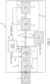
- the aircraft hybrid electrical system 40 includes an electric power generating system 50, a secondary power system 60, a battery 70, and a system controller 80.
- the electric power generating system 50, the secondary power system 60, and the battery 70 are connected in common with one another via a power bus 45 to facilitate signal communication (e.g., voltage and current) between one another.
- the electric power generating system 50 is operable with a thermal combustion engine 14 included in a corresponding engine system 30.
- the electric power generating system 50 includes a motor generator 52 and a motor controller and rectifier 54.
- the motor generator 52 can be selectively invoked to operate according to different operating modes.
- the motor generator 52 can produce torque to drive the thermal engine 14 and provide thrust when operating in a first mode (e.g., a motor mode), but can generate electric power in response to receiving rotational energy from the thermal engine 14 when operating in a second mode (e.g., a generator mode).
- the motor controller and rectifier 54 can generate a control signal 55 that invokes the different operating modes of the motor generator 52.
- the motor controller and rectifier 54 can rectify the alternating current (AC) power generated by the motor generator 52 to generate direct current (DC) power 57 (e.g., the direct current and DC voltage).
- the DC power 57 is applied to the power bus 45 and defines a bus volage and bus current, which can be utilized by the secondary power system 60 and/or the battery 70 as described herein.
- the secondary power system 60 includes a power converter 62 and one or more aircraft loads 64.
- the power converter 62 receives an input power 59 from the electric power generating system 50 and/or the battery 70 and converts it into secondary power 63 (e.g., secondary voltage) having different characteristics (e.g., a different type of electrical power or a different voltage level).
- the power converter 62 can include a DC-to-DC (DC/DC) converter and/or DC-to-AC (DC/AC) converter.
- the DC/DC or DC/AC converters can be construed in a variety or topologies, and configured to convert a variable voltage into a constant voltage for use in voltage sensitive secondary systems and/or to drive one or more of the aircraft loads 64.
- the DC/DC converter receives an input DC voltage and outputs a lower DC voltage.
- the DC/AC converter is configured to convert DC power into AC power (e.g., three-phase AC power) for alternating current architectures or architectures that operated at a targeted frequency (e.g., 400 Hz).
- the battery 70 is configured as a high-performance battery such as, for example, re-chargeable a lithium ion (Li-ion) battery.
- the battery 70 is configured to provide stored energy, which can be output and utilized for aircraft propulsion and/or the secondary system 60.
- the battery 70 can be charged using power generated by the motor/generator 52 and output from the electric power generating system 50.
- the system controller 80 is in signal communication with the electric power generating system 50, the secondary power system 60, and the battery 70.
- the system controller 80 is configured to monitor sensed current and/or voltage data corresponding to the electric power generating system 50, the secondary power system 60, and/or the battery 70, and control the electric power generating system 50, based on the sensed currents and/or voltages.
- the sensed current and/or voltage data includes generator sensed current/voltages 90 (e.g., output from one or more generator sensors), power converter sensed current/voltages 92 (e.g., output from one or more power converter sensors), sensed aircraft load current/voltages 93 (e.g., output from one or more load sensors), and battery sensed current/voltages 94 (e.g., output from one or more battery sensors).
- generator sensed current/voltages 90 e.g., output from one or more generator sensors
- power converter sensed current/voltages 92 e.g., output from one or more power converter sensors
- sensed aircraft load current/voltages 93 e.g., output from one or more load sensors
- battery sensed current/voltages 94 e.g., output from one or more battery sensors.
- the system controller 80 Based on the sensed current and/or voltage data 90, 92, 93, and/or 94, (and in some embodiments additional inputs from ancillary engine and/or airframe controllers) the system controller 80 is configured to output one or more control signals 96 that controls the operation of the electric power generating system 50 (e.g., the motor/generator 52 and/or the motor controller/rectifier 54). In one or more non-limiting embodiments, the system controller 80 can also monitor the sensed current and/or voltage data 90, 92, 93, and/or 94 and output control signals 96 that provide overload and fault protection.
- the system controller 80 can also monitor the sensed current and/or voltage data 90, 92, 93, and/or 94 and output control signals 96 that provide overload and fault protection.
- the control signals 96 generated by the system controller 80 are used to maintain the voltage (e.g., the bus voltage) on the power bus 45 at a targeted bus voltage level to properly operate the battery 70 while also providing power to the power converter 62.
- the system controller 80 is configured to first prioritize battery current and voltage to properly charge the battery 70. Accordingly, the system controller 80 can monitor the battery sensed current/voltages 94 and generate control signals 96 to actively control the electric power generating system 50 to output DC power 57 that ensures the battery 70 is properly charged and the power converter 62 consumes the necessary power for driving the aircraft loads 64.
- an aircraft hybrid electrical system 40 is illustrated according to another non-limiting embodiment of the present disclosure.
- the architecture of the aircraft hybrid electrical system 40 shown in FIG. 4 is similar to the architecture of the aircraft hybrid electrical system 40 shown in FIG. 3 , but includes a high-spool motor generator 52a and a low-spool motor generator 52b.
- the high-spool motor/generator 52a corresponds to the high spool 3 and 5 of the engine 14 and can be controlled by a first motor controller 54a.
- the low-spool motor/generator 52b corresponds to the low spool 2 and 6 of the engine 14 and can be controlled by a second motor controller 54b.
- the system controller 80 included in either embodiment illustrated in FIGS. 3 or 4 stores a charging profile that is designed specifically for the battery 70. Accordingly, the system controller 80 can selectively invoke different charging modes to control the electric power generating system 50 to charge the battery 70 according to the charging profile.
- the system 40 is configured to use inter-changeable batteries 70. For example, the battery 70 can be swapped out and changed with a different battery as battery technologies change over time or as the battery 70 ages over time. Accordingly, the charging profile stored in the system controller 80 can be changed or updated as the battery 70 used in the system 40 is inter-changed or swapped out.
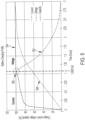
- FIG. 5 illustrates a charging profile 500 for charging a high-performance battery 70 according to a non-limiting embodiment.
- the charging profile 500 defines a target current profile 502 and target voltage profile 504.
- the charging profile 500 is stored in the system controller 80. Accordingly, the system controller 80 can selectively operate in a target current mode and a target voltage mode to ensure the battery 70 is charged according to the charging profile 500.
- the system controller can initially invoke the target current mode.
- the system controller 80 In response to invoking the target current mode, the system controller 80 generates control signals 96 that control the electric power generating system 50 to output current that is delivered to the battery 70.
- the system controller 80 monitors the sensed battery current and voltages 94 and actively controls the electric power generating system 50 (using the control signals 96) to achieve the target current profile 502 defined by the charging profile 500.
- the controller 80 invokes the target voltage mode.
- the target voltage level 506 corresponds to the transition point when a particular cell voltage is reached.
- the target current mode is invoked to hold the battery 70 constant at that cell voltage and to increase the battery capacity 508 the remainder of the way to 100% (e.g., from about 62% to 100%).
- the system controller 80 In response to invoking the target voltage mode, the system controller 80 generates control signals 96 that control the electric power generating system 50 to output current that is delivered to the battery 70, which in turn maintains the battery 70 at the target voltage level 506 (e.g., about 4.2 V). Accordingly, current consumption by the battery 70 begins reducing while the battery 70 is maintained at full (e.g., 100%) cell voltage while the battery 70 is being fully charged to full (e.g., 100%) cell capacity.
- the target voltage level 506 e.g., about 4.2 V
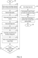
- FIG. 6 a method of operating a hybrid electric secondary power and battery charging control system (also referred to herein as a hybrid electrical system 40) is illustrated according to a non-limiting embodiment of the present disclosure.
- the method begins at operation 600, and at operation 602 the sensed current/voltages 90, 92, 93, and 94 of the electric power generating system 50, the secondary power system 60, and the battery 70 are monitored.
- the current charge capacity of a high performance battery 70 included in the hybrid electrical system 40 is determined.
- a determination is made to charge the battery 70 in response to the battery charge capacity falling below a charge capacity threshold.
- the battery charge capacity ranges from a first charge capacity value indicative of an empty charge capacity of the battery 70 to a second charge capacity indicative of a full charge capacity of the battery, and the charge capacity threshold is set as a threshold value between the first charge capacity value and the second charge capacity value.
- the system controller 80 can be selectively operated in the in the voltage charge mode and the current charge mode to charge the battery from the threshold value to the full charge capacity of the battery.
- an electrical current charge mode of the system controller 80 is initiated.
- the system controller 80 generates control signals 96 to control a electric power generating system 50 and output DC power 57.
- electrical current corresponding to the DC power 57 is used to charge the battery 70 according to a charging profile.
- the system controller 80 monitors the current charging capacity and cell voltage 94 of the battery 70.
- the system controller 80 determines whether the cell voltage has reached a target voltage. When the cell voltage does not reach the target voltage, the method returns to operation 612 and the electrical current continues to charge the battery 70 according to the charging profile.
- the system controller 80 invokes a voltage charging mode at operation 618.
- the system controller 80 outputs control signals 96 to actively control the electric power generating system 50 and adjust the DC power 57 so that the cell voltage is maintained at the target voltage and the battery 70 is maintained at a target charge capacity.
- the system controller 80 continues monitoring the sensed battery current/voltage 94, and the method ends at operation 624.
Landscapes
- Engineering & Computer Science (AREA)
- Power Engineering (AREA)
- Aviation & Aerospace Engineering (AREA)
- Transportation (AREA)
- Mechanical Engineering (AREA)
- Charge And Discharge Circuits For Batteries Or The Like (AREA)
- Secondary Cells (AREA)
Abstract
Description
- Embodiments of the present disclosure relate generally to aircraft electrical systems and, in particular, to hybrid propulsion aircraft electrical architectures that implement a secondary power system and a high-performance battery system.
- Traditional aircraft electrical systems operate at a constant regulated voltage typically only control current in the event of a current overload or electrical fault. Recently, aircraft electrical systems are trending toward hybrid propulsion architecture designs (referring to herein simply as hybrid electrical architectures). These hybrid electrical architectures implement both a secondary power system along with a battery power system. The battery power system employs a high-performance battery such as, for example, a lithium ion (Li-ion) battery. Conventional hybrid electrical architectures are designed to include a dedicated battery charging system to provide current and voltage charging profiles tailored to charge the specific high-performance battery utilized in the battery power system. In the past, the high-performance battery was simply used to provide backup power for low-load components but in systems that include a high capacity battery, the added weight, volume, and thermal losses of this battery charging system results in significant vehicle penalties.
- According to a non-limiting embodiment, an aircraft hybrid electrical system comprises an electric power generating system in signal communication with a thermal combustion engine, a secondary power system in signal communication with the electric power generating system, and a battery in signal communication with the electric power generating system and the secondary power system. The aircraft hybrid electrical system further comprises a system controller in signal communication with the electric power generating system, secondary power system, and the battery. The system controller is configured to monitor a charge capacity of the battery and selectively operate in a current charge mode and a voltage charge mode to charge the battery. The system controller invokes the current charge mode in response to detecting the charge capacity falls below a charge capacity threshold, and invokes the voltage charge mode in response to detecting the charge capacity reaches a target value.
- According to one or more non-limiting embodiments, the aircraft hybrid electrical system further includes a feature, wherein the charge capacity ranges from a first charge capacity value indicative of an empty charge capacity of the battery to a second charge capacity indicative of a full charge capacity of the battery. In one or more non-limiting embodiments, and the charge capacity threshold is a threshold value between the first charge capacity value and the second charge capacity value.
- According to one or more non-limiting embodiments, the aircraft hybrid electrical system further includes a feature, wherein the system controller operates in the voltage charge mode while the battery charges from the threshold value to the full capacity.
- According to one or more non-limiting embodiments, the aircraft hybrid electrical system further comprise a power bus that establishes the signal communication between the power generating system, the secondary power system, and the battery.
- According to one or more non-limiting embodiments, the aircraft hybrid electrical system further includes a feature, wherein system controller monitors a bus voltage present on the power bus, and maintains the bus voltage at a targeted bus voltage level to charge the battery according to the current and voltage charge modes while providing power to the secondary power system.
- According to one or more non-limiting embodiments, the aircraft hybrid electrical system further includes a feature wherein the system controller controls the electric power generating system to generate the bus voltage based on the operation of the thermal combustion engine, and wherein the power bus delivers the bus voltage to the battery and the secondary power system.
- According to one or more non-limiting embodiments, the aircraft hybrid electrical system further includes a feature wherein the secondary power system converts the bus voltage into a secondary voltage, and delivers the secondary voltage to at least one aircraft load.
- According to another non-limiting embodiment, an aircraft hybrid electrical system comprises an electric power generating system, a secondary power system, a battery, and a system controller. The electric power generating system is in signal communication with a high spool of a thermal combustion engine and a low spool of the thermal combustion engine. The secondary power system is in signal communication with the electric power generating system. The battery is in signal communication with the electric power generating system and the secondary power system. The system controller is in signal communication with the electric power generating system, the secondary power system, and the battery. The system controller is configured to monitor a charge capacity of the battery and selectively operate in a current charge mode and a voltage charge mode to charge the battery. The system controller invokes the current charge mode in response to detecting the charge capacity falls below a charge capacity threshold, and invokes the voltage charge mode in response to detecting the charge capacity reaches a target value.
- According to one or more non-limiting embodiments, the aircraft hybrid electrical system further includes a feature wherein the electric power generating system comprises a first motor generator configured to generate a first alternating current (AC) voltage in response to operating the high spool, a first motor controller configured to rectify the first AC voltage to generate a first direct current (DC) voltage, and a second motor generator configured to generate a second AC voltage in response to operating the high spool, and a first motor controller configured to rectify the second AC voltage to generate a second DC voltage.
- According to one or more non-limiting embodiments, the aircraft hybrid electrical system further includes a feature wherein the charge capacity ranges from a first charge capacity value indicative of an empty charge capacity of the battery to a second charge capacity indicative of a full charge capacity of the battery. In one or more non-limiting embodiments, the charge capacity threshold is a threshold value between the first charge capacity value and the second charge capacity value.
- According to one or more non-limiting embodiments, the aircraft hybrid electrical system further includes a feature wherein the system controller operates in the voltage charge mode while the battery charges from the threshold value to the full capacity.
- According to one or more non-limiting embodiments, the aircraft hybrid electrical system further comprises a power bus that establishes the signal communication between the power generating system, the secondary power system, and the battery.
- According to one or more non-limiting embodiments, the aircraft hybrid electrical system further includes a feature wherein system controller monitors a bus voltage present on the power bus, and maintains the bus voltage at a targeted bus voltage level to charge the battery according to the current and voltage charge modes while providing power to the secondary power system.
- According to one or more non-limiting embodiments, the aircraft hybrid electrical system further includes a feature wherein one or both of the first DC voltage and the second DC voltage is delivered to the power bus to generate the bus voltage, and wherein the power bus delivers the bus voltage to the battery and the secondary power system.
- According to one or more non-limiting embodiments, the aircraft hybrid electrical system further includes a feature wherein the system controller controls one or both of the first motor controller and the second motor controller to adjust the bus voltage delivered to the power bus based on the operation of the thermal combustion engine.
- According to one or more non-limiting embodiments, the aircraft hybrid electrical system further includes a feature wherein the secondary power system converts the bus voltage into a secondary voltage, and delivers the secondary voltage to at least one aircraft load.
- According to yet another non-limiting embodiment, a method is provided for charging a battery included in an aircraft hybrid electrical system comprising. The method comprises generating, by an electric power generating system, an electric power based on operation of a thermal combustion engine; converting, by a secondary power system, the electric power into a secondary power; delivering the electric power to a battery; monitoring, by a system controller, a charge capacity of the battery; invoking a current charge mode of the system controller in response to detecting the charge capacity falling below a charge capacity threshold to increase the charge capacity of the battery; and switching the system controller from the current charge mode to a voltage charge mode of the system controller in response to detecting the charge capacity reaches a target value to continue charging the battery so that the charge capacity reaches a full capacity.
- According to one or more non-limiting embodiments, the aircraft hybrid electrical system includes a feature, wherein the charge capacity ranges from a first charge capacity value indicative of an empty charge capacity of the battery to a second charge capacity indicative of the full charge capacity. According to one or more non-limiting embodiments, the charge capacity threshold is a threshold value between the first charge capacity value and the second charge capacity value.
- According to one or more non-limiting embodiments, the method further comprises operating the system controller in the voltage charge mode while the battery charges from the threshold value to the full capacity.
- According to one or more non-limiting embodiments, the method further comprises outputting the electric power from the electric power generating system to a power bus connected to the secondary power system and the battery; monitoring, using the system controller, a bus voltage present on the power bus; and maintaining the bus voltage at a targeted bus voltage level to charge the battery according to the current and voltage charge modes while providing the electric power to the secondary power system.
- The following descriptions should not be considered limiting in any way. With reference to the accompanying drawings, like elements are numbered alike:
-
FIG. 1 depicts an aircraft comprising a propulsion system including one or more engine systems according to a non-limiting embodiment of the present disclosure; -
FIG. 2 is a block diagram illustrating an engine system according to a non-limiting embodiment of the present disclosure; -
FIG. 3 is a block diagram of an aircraft hybrid electrical system according to a non-limiting embodiment of the present disclosure; -
FIG. 4 is a block diagram of an aircraft hybrid electrical system according to a non-limiting embodiment of the present disclosure; -
FIG. 5 is a diagram illustrating a target charging current profile and cell voltage profile for charging a high-performance battery over time a non-limiting embodiment of the present disclosure; and -
FIG. 6 is a flow diagram illustrating a method of operating a hybrid electric secondary power and battery charging control system according to a non-limiting embodiment of the present disclosure. - A detailed description of one or more embodiments of the disclosed apparatus and method are presented herein by way of exemplification and not limitation with reference to the Figures.
- Current trends in aircraft hybrid electrical architectures is to employ a high-performance battery to power additional loads, which require a larger dedicated battery charging unit (referred to simply as a battery charger) than used in previously designed hybrid electrical systems. As a result, the battery chargers necessary for charging the larger-sized batteries have themselves become larger and require additional components. The increased weight and complexity of the battery charger, however, increases the overall weight of the aircraft and therefore contributes to reduced fuel efficiency of the aircraft.
- Embodiments of the present disclosure provide an aircraft hybrid electrical system that includes a secondary power system and a high-performance battery. Unlike conventional systems, non-limiting embodiments of the aircraft hybrid electrical system described herein employ a power control system capable of charging the high-performance battery without implementing a dedicated battery charger. In this manner, a charging profile tailored to the high-performance battery is still provided while also reducing the overall weight of the aircraft.
- With reference now to
FIG. 1 , an aircraft 1 is illustrated according to a non-limiting embodiment. The aircraft 1 includes a propulsion system including one ormore engine systems 30 and a hybridelectrical system 40. -
FIG. 2 depicts anengine system 30 according to a non-limiting embodiment. Theengine system 30 includes athermal combustion engine 14 including acombustor chamber 4 and may include one or more compressor sections (e.g., a lowpressure compressor section 2, a high pressure compressor section 3), and one or more turbine sections (e.g., a highpressure turbine section 5 and a low pressure turbine section 6). Thethermal combustion engine 14 may comprise a rotating shaft or a first shaft 9 (e.g., a low pressure shaft) which may connect a lowpressure compressor section 2 and a low pressure turbine section 6. Thethermal combustion engine 14 may comprise a second shaft 8 (e.g. a high pressure shaft) which may connect a highpressure compressor section 3 and a highpressure turbine section 5. A shaft of the engine (e.g., the first shaft 9) may be connected to apropulsor 10 via a connection means 12 (e.g., a gearbox). In one or more embodiments, thethermal combustion engine 14 operates in conjunction with an electricpower generating system 50 as described in greater detail below. - Turning now to
FIG. 3 , an aircraft hybridelectrical system 40 is illustrated according to a non-limiting embodiment of the present disclosure. The aircraft hybridelectrical system 40 may be referred to as a "parallel hybrid propulsion system," and may correspond to one or both of theengine systems FIGS. 1 and2 . The aircraft hybridelectrical system 40 includes an electricpower generating system 50, asecondary power system 60, abattery 70, and asystem controller 80. The electricpower generating system 50, thesecondary power system 60, and thebattery 70 are connected in common with one another via a power bus 45 to facilitate signal communication (e.g., voltage and current) between one another. - The electric
power generating system 50 is operable with athermal combustion engine 14 included in acorresponding engine system 30. The electricpower generating system 50 includes amotor generator 52 and a motor controller and rectifier 54. Themotor generator 52 can be selectively invoked to operate according to different operating modes. For example, themotor generator 52 can produce torque to drive thethermal engine 14 and provide thrust when operating in a first mode (e.g., a motor mode), but can generate electric power in response to receiving rotational energy from thethermal engine 14 when operating in a second mode (e.g., a generator mode). The motor controller and rectifier 54 can generate a control signal 55 that invokes the different operating modes of themotor generator 52. In addition, the motor controller and rectifier 54 can rectify the alternating current (AC) power generated by themotor generator 52 to generate direct current (DC) power 57 (e.g., the direct current and DC voltage). The DC power 57 is applied to the power bus 45 and defines a bus volage and bus current, which can be utilized by thesecondary power system 60 and/or thebattery 70 as described herein. - The
secondary power system 60 includes apower converter 62 and one or more aircraft loads 64. Thepower converter 62 receives aninput power 59 from the electricpower generating system 50 and/or thebattery 70 and converts it into secondary power 63 (e.g., secondary voltage) having different characteristics (e.g., a different type of electrical power or a different voltage level). Thepower converter 62 can include a DC-to-DC (DC/DC) converter and/or DC-to-AC (DC/AC) converter. The DC/DC or DC/AC converters can be construed in a variety or topologies, and configured to convert a variable voltage into a constant voltage for use in voltage sensitive secondary systems and/or to drive one or more of the aircraft loads 64. In one or more non-limiting embodiments, the DC/DC converter receives an input DC voltage and outputs a lower DC voltage. The DC/AC converter is configured to convert DC power into AC power (e.g., three-phase AC power) for alternating current architectures or architectures that operated at a targeted frequency (e.g., 400 Hz). - The
battery 70 is configured as a high-performance battery such as, for example, re-chargeable a lithium ion (Li-ion) battery. Thebattery 70 is configured to provide stored energy, which can be output and utilized for aircraft propulsion and/or thesecondary system 60. In one or more non-limiting embodiments, thebattery 70 can be charged using power generated by the motor/generator 52 and output from the electricpower generating system 50. - The
system controller 80 is in signal communication with the electricpower generating system 50, thesecondary power system 60, and thebattery 70. Thesystem controller 80 is configured to monitor sensed current and/or voltage data corresponding to the electricpower generating system 50, thesecondary power system 60, and/or thebattery 70, and control the electricpower generating system 50, based on the sensed currents and/or voltages. The sensed current and/or voltage data includes generator sensed current/voltages 90 (e.g., output from one or more generator sensors), power converter sensed current/voltages 92 (e.g., output from one or more power converter sensors), sensed aircraft load current/voltages 93 (e.g., output from one or more load sensors), and battery sensed current/voltages 94 (e.g., output from one or more battery sensors). Based on the sensed current and/orvoltage data system controller 80 is configured to output one or more control signals 96 that controls the operation of the electric power generating system 50 (e.g., the motor/generator 52 and/or the motor controller/rectifier 54). In one or more non-limiting embodiments, thesystem controller 80 can also monitor the sensed current and/orvoltage data - The control signals 96 generated by the
system controller 80 are used to maintain the voltage (e.g., the bus voltage) on the power bus 45 at a targeted bus voltage level to properly operate thebattery 70 while also providing power to thepower converter 62. In one or more non-limiting embodiments, thesystem controller 80 is configured to first prioritize battery current and voltage to properly charge thebattery 70. Accordingly, thesystem controller 80 can monitor the battery sensed current/voltages 94 and generatecontrol signals 96 to actively control the electricpower generating system 50 to output DC power 57 that ensures thebattery 70 is properly charged and thepower converter 62 consumes the necessary power for driving the aircraft loads 64. - Referring to
FIG. 4 , an aircraft hybridelectrical system 40 is illustrated according to another non-limiting embodiment of the present disclosure. The architecture of the aircraft hybridelectrical system 40 shown inFIG. 4 is similar to the architecture of the aircraft hybridelectrical system 40 shown inFIG. 3 , but includes a high-spool motor generator 52a and a low-spool motor generator 52b. The high-spool motor/generator 52a corresponds to thehigh spool engine 14 and can be controlled by afirst motor controller 54a. The low-spool motor/generator 52b corresponds to thelow spool 2 and 6 of theengine 14 and can be controlled by asecond motor controller 54b. Although two separate andindividual motor controllers generator 52a and the low-spool motor/generator 52b without departing from the scope of the invention. Accordingly, the remaining components and systems (e.g., the electricpower generating system 50, thesecondary power system 60, thebattery 70 and the system controller 80) of the aircraft hybridelectrical system 40 illustrated inFIG. 4 operate similar to those included in the aircraft hybridelectrical system 40 shown inFIG. 3 . Therefore, descriptions of the remaining components and systems will not be repeated for the sake of brevity. - In one or more non-limiting embodiments, the
system controller 80 included in either embodiment illustrated inFIGS. 3 or4 stores a charging profile that is designed specifically for thebattery 70. Accordingly, thesystem controller 80 can selectively invoke different charging modes to control the electricpower generating system 50 to charge thebattery 70 according to the charging profile. In one or more non-limiting embodiments, thesystem 40 is configured to useinter-changeable batteries 70. For example, thebattery 70 can be swapped out and changed with a different battery as battery technologies change over time or as thebattery 70 ages over time. Accordingly, the charging profile stored in thesystem controller 80 can be changed or updated as thebattery 70 used in thesystem 40 is inter-changed or swapped out. -
FIG. 5 illustrates a charging profile 500 for charging a high-performance battery 70 according to a non-limiting embodiment. The charging profile 500 defines a targetcurrent profile 502 andtarget voltage profile 504. As described herein, the charging profile 500 is stored in thesystem controller 80. Accordingly, thesystem controller 80 can selectively operate in a target current mode and a target voltage mode to ensure thebattery 70 is charged according to the charging profile 500. - When there is a need to charge the
battery 70, the system controller can initially invoke the target current mode. In response to invoking the target current mode, thesystem controller 80 generates control signals 96 that control the electricpower generating system 50 to output current that is delivered to thebattery 70. Thesystem controller 80 monitors the sensed battery current andvoltages 94 and actively controls the electric power generating system 50 (using the control signals 96) to achieve the targetcurrent profile 502 defined by the charging profile 500. - When the
system controller 80 determines that atarget voltage level 506 is achieved (e.g., about 4.2 V at about (t) = 0.625), thecontroller 80 invokes the target voltage mode. In one or more non-limiting embodiment, thetarget voltage level 506 corresponds to the transition point when a particular cell voltage is reached. Once thetarget voltage level 506 is reached, the target current mode is invoked to hold thebattery 70 constant at that cell voltage and to increase thebattery capacity 508 the remainder of the way to 100% (e.g., from about 62% to 100%). In response to invoking the target voltage mode, thesystem controller 80 generates control signals 96 that control the electricpower generating system 50 to output current that is delivered to thebattery 70, which in turn maintains thebattery 70 at the target voltage level 506 (e.g., about 4.2 V). Accordingly, current consumption by thebattery 70 begins reducing while thebattery 70 is maintained at full (e.g., 100%) cell voltage while thebattery 70 is being fully charged to full (e.g., 100%) cell capacity. - Turning now to
FIG. 6 , a method of operating a hybrid electric secondary power and battery charging control system (also referred to herein as a hybrid electrical system 40) is illustrated according to a non-limiting embodiment of the present disclosure. The method begins atoperation 600, and atoperation 602 the sensed current/voltages power generating system 50, thesecondary power system 60, and thebattery 70 are monitored. At operation 604, the current charge capacity of ahigh performance battery 70 included in the hybridelectrical system 40 is determined. Atoperation 606, a determination is made to charge thebattery 70 in response to the battery charge capacity falling below a charge capacity threshold. In one or more non-limiting embodiments, the battery charge capacity ranges from a first charge capacity value indicative of an empty charge capacity of thebattery 70 to a second charge capacity indicative of a full charge capacity of the battery, and the charge capacity threshold is set as a threshold value between the first charge capacity value and the second charge capacity value. Accordingly, thesystem controller 80 can be selectively operated in the in the voltage charge mode and the current charge mode to charge the battery from the threshold value to the full charge capacity of the battery. Turning tooperation 608, an electrical current charge mode of thesystem controller 80 is initiated. Atoperation 610, thesystem controller 80 generates control signals 96 to control a electricpower generating system 50 and output DC power 57. Atoperation 612, electrical current corresponding to the DC power 57 is used to charge thebattery 70 according to a charging profile. Atoperation 614, thesystem controller 80 monitors the current charging capacity andcell voltage 94 of thebattery 70. At 616, thesystem controller 80 determines whether the cell voltage has reached a target voltage. When the cell voltage does not reach the target voltage, the method returns tooperation 612 and the electrical current continues to charge thebattery 70 according to the charging profile. - When, however, the battery cell voltage reaches the target voltage, the
system controller 80 invokes a voltage charging mode atoperation 618. Atoperation 620, thesystem controller 80 outputs control signals 96 to actively control the electricpower generating system 50 and adjust the DC power 57 so that the cell voltage is maintained at the target voltage and thebattery 70 is maintained at a target charge capacity. Atoperation 622, thesystem controller 80 continues monitoring the sensed battery current/voltage 94, and the method ends atoperation 624. - The term "about" is intended to include the degree of error associated with measurement of the particular quantity based upon the equipment available at the time of filing the application.
- The terminology used herein is for the purpose of describing particular embodiments only and is not intended to be limiting of the present disclosure. As used herein, the singular forms "a", "an" and "the" are intended to include the plural forms as well, unless the context clearly indicates otherwise. It will be further understood that the terms "comprises" and/or "comprising," when used in this specification, specify the presence of stated features, integers, steps, operations, elements, and/or components, but do not preclude the presence or addition of one or more other features, integers, steps, operations, element components, and/or groups thereof.
- While the present disclosure has been described with reference to an exemplary embodiment or embodiments, it will be understood by those skilled in the art that various changes may be made and equivalents may be substituted for elements thereof without departing from the scope of the present disclosure. In addition, many modifications may be made to adapt a particular situation or material to the teachings of the present disclosure without departing from the essential scope thereof. Therefore, it is intended that the present disclosure not be limited to the particular embodiment disclosed as the best mode contemplated for carrying out this present disclosure, but that the present disclosure will include all embodiments falling within the scope of the claims.
Claims (15)
- An aircraft hybrid electrical system comprising:an electric power generating system (50) in signal communication with a thermal combustion engine (14);a secondary power system (60) in signal communication with the electric power generating system (50);a battery (70) in signal communication with the electric power generating system (50) and the secondary power system (60); anda system controller (80) in signal communication with the electric power generating system (50), the secondary power system (60), and the battery (70), the system controller (80) configured to monitor a charge capacity of the battery (70) and selectively operate in a current charge mode and a voltage charge mode to charge the battery (70),wherein the system controller (80) invokes the current charge mode in response to detecting the charge capacity falls below a charge capacity threshold and invokes the voltage charge mode in response to detecting the charge capacity reaches a target value.
- The aircraft hybrid electrical system of claim 1, wherein the charge capacity ranges from a first charge capacity value indicative of an empty charge capacity of the battery (70) to a second charge capacity indicative of a full charge capacity of the battery (70), and the charge capacity threshold is a threshold value between the first charge capacity value and the second charge capacity value.
- The aircraft hybrid electrical system of claim 1 or 2, wherein the system controller (80) operates in the voltage charge mode while the battery (70) charges from the threshold value to the full capacity, and optionally further comprising a power bus that establishes the signal communication between the power generating system (50), the secondary power system (60), and the battery (70).
- The aircraft hybrid electrical system of any preceding claim, wherein system controller (80) monitors a bus voltage present on the power bus, and maintains the bus voltage at a targeted bus voltage level to charge the battery (70) according to the current and voltage charge modes while providing power to the secondary power system (60), or
wherein the system controller (80) controls the electric power generating system (50) to generate the bus voltage based on the operation of the thermal combustion engine (14), and wherein the power bus delivers the bus voltage to the battery (70) and the secondary power system (60). - The aircraft hybrid electrical system of any preceding claim, wherein the secondary power system (60) converts the bus voltage into a secondary voltage, and delivers the secondary voltage to at least one aircraft load.
- An aircraft hybrid electrical system comprising:an electric power generating system (50) in signal communication with a high spool of a thermal combustion engine (14) and a low spool of the thermal combustion engine (14);a secondary power system (60) in signal communication with the electric power generating system (50);a battery (70) in signal communication with the electric power generating system (50) and the secondary power system (60); anda system controller (80) in signal communication with the electric power generating system (50), the secondary power system (60), and the battery (70), the system controller (80) configured to monitor a charge capacity of the battery (70) and selectively operate in a current charge mode and a voltage charge mode to charge the battery (70),wherein the system controller (80) invokes the current charge mode in response to detecting the charge capacity falls below a charge capacity threshold and invokes the voltage charge mode in response to detecting the charge capacity reaches a target value.
- The aircraft hybrid electrical system of claim 6, wherein the electric power generating system (50) comprises:a first motor generator configured to generate a first alternating current (AC) voltage in response to operating the high spool;a first motor controller configured to rectify the first AC voltage to generate a first direct current (DC) voltage;a second motor generator configured to generate a second AC voltage in response to operating the high spool; anda first motor controller configured to rectify the second AC voltage to generate a second DC voltage.
- The aircraft hybrid electrical system of claim 7, wherein the charge capacity ranges from a first charge capacity value indicative of an empty charge capacity of the battery (70) to a second charge capacity indicative of a full charge capacity of the battery (70), and the charge capacity threshold is a threshold value between the first charge capacity value and the second charge capacity value.
- The aircraft hybrid electrical system of claim 8, wherein the system controller (80) operates in the voltage charge mode while the battery (70) charges from the threshold value to the full capacity.
- The aircraft hybrid electrical system of claim 9, further comprising a power bus that establishes the signal communication between the power generating system (50), the secondary power system (60), and the battery (70), and optionally wherein the system controller (80) monitors a bus voltage present on the power bus, and maintains the bus voltage at a targeted bus voltage level to charge the battery (70) according to the current and voltage charge modes while providing power to the secondary power system (60).
- The aircraft hybrid electrical system of claim 10, wherein one or both of the first DC voltage and the second DC voltage is delivered to the power bus to generate the bus voltage, and wherein the power bus delivers the bus voltage to the battery (70) and the secondary power system (60).
- The aircraft hybrid electrical system of claim 11, wherein the system controller (80) controls one or both of the first motor controller and the second motor controller to adjust the bus voltage delivered to the power bus based on the operation of the thermal combustion engine (14), and/or . wherein the secondary power system (60) converts the bus voltage into a secondary voltage, and delivers the secondary voltage to at least one aircraft load.
- A method of charging a battery (70) included in an aircraft hybrid electrical system comprising, the method comprising:generating, by an electric power generating system (50), an electric power based on operation of a thermal combustion engine (14);converting, by a secondary power system (60), the electric power into a secondary power;delivering the electric power to a battery (70);monitoring, by a system controller (80), a charge capacity of the battery (70);invoking a current charge mode of the system controller (80) in response to detecting the charge capacity falling below a charge capacity threshold to increase the charge capacity of the battery (70); andswitching the system controller (80) from the current charge mode to a voltage charge mode of the system controller (80) in response to detecting the charge capacity reaches a target value to continue charging the battery (70) so that the charge capacity reaches a full capacity.
- The method of claim 13, wherein the charge capacity ranges from a first charge capacity value indicative of an empty charge capacity of the battery (70) to a second charge capacity indicative of the full charge capacity, and wherein the charge capacity threshold is a threshold value between the first charge capacity value and the second charge capacity value.
- The method of claim 13 or 14, further comprising operating the system controller (80) in the voltage charge mode while the battery (70) charges from the threshold value to the full capacity, and/or .
further comprising:outputting the electric power from the electric power generating system (50) to a power bus connected to the secondary power system (60) and the battery (70);monitoring, using the system controller (80), a bus voltage present on the power bus; andmaintaining the bus voltage at a targeted bus voltage level to charge the battery (70) according to the current and voltage charge modes while providing the electric power to the secondary power system (60).
Applications Claiming Priority (1)
| Application Number | Priority Date | Filing Date | Title |
|---|---|---|---|
| US17/746,570 US12003132B2 (en) | 2022-05-17 | 2022-05-17 | Hybrid electric secondary power and battery charging architecture and control system |
Publications (1)
| Publication Number | Publication Date |
|---|---|
| EP4280419A1 true EP4280419A1 (en) | 2023-11-22 |
Family
ID=86378583
Family Applications (1)
| Application Number | Title | Priority Date | Filing Date |
|---|---|---|---|
| EP23173127.4A Pending EP4280419A1 (en) | 2022-05-17 | 2023-05-12 | Hybrid electric secondary power and battery charging architecture and control system |
Country Status (2)
| Country | Link |
|---|---|
| US (1) | US12003132B2 (en) |
| EP (1) | EP4280419A1 (en) |
Citations (2)
| Publication number | Priority date | Publication date | Assignee | Title |
|---|---|---|---|---|
| EP1414101B1 (en) * | 2002-10-11 | 2008-05-28 | Canon Kabushiki Kaisha | Detecting method and detecting apparatus for detecting internal resistance of a rechargeable battery and rechargeable battery pack having said detecting apparatus therein |
| WO2021039475A1 (en) * | 2019-08-26 | 2021-03-04 | 三菱重工業株式会社 | Power distribution system and power distribution method |
Family Cites Families (15)
| Publication number | Priority date | Publication date | Assignee | Title |
|---|---|---|---|---|
| KR100265709B1 (en) * | 1996-10-15 | 2000-09-15 | 윤종용 | A secondary charginf apparatus |
| US8128019B2 (en) | 2008-12-12 | 2012-03-06 | Honeywell International Inc. | Hybrid power for ducted fan unmanned aerial systems |
| DE102012209807A1 (en) | 2012-06-12 | 2013-12-12 | Siemens Aktiengesellschaft | Airplane and method for manufacturing an aircraft |
| US9614258B2 (en) * | 2012-12-28 | 2017-04-04 | Semiconductor Energy Laboratory Co., Ltd. | Power storage device and power storage system |
| EP2971594B1 (en) | 2013-03-14 | 2020-01-08 | Rolls-Royce Corporation | Hybrid turbo electric aero-propulsion system control |
| US10608565B2 (en) * | 2017-12-07 | 2020-03-31 | General Electric Company | Systems and methods for rotating a crankshaft to start an engine |
| US11214378B2 (en) * | 2018-08-21 | 2022-01-04 | Zunum Aero, Inc. | System controller for series hybrid powertrain |
| US11233470B2 (en) | 2018-09-06 | 2022-01-25 | Pratt & Whitney Canada Corp. | Synchronization of generator and electric motor in a hybrid electric aircraft propulsion system |
| FR3085667B1 (en) | 2018-09-12 | 2020-11-20 | Safran | SERIES HYBRID PROPULSION KIT FOR AIRCRAFT |
| FR3086923B1 (en) | 2018-10-04 | 2020-11-06 | Safran | ELECTRICAL ARCHITECTURE FOR HYBRID PROPULSION |
| FR3093080B1 (en) | 2019-02-26 | 2021-03-05 | Safran Helicopter Engines | HYBRID-ELECTRIC PROPULSIVE ARCHITECTURE AND ELECTRICAL ENERGY DISSIPATION PROCESS IN SUCH ARCHITECTURE |
| EP3772462A1 (en) | 2019-08-05 | 2021-02-10 | Hamilton Sundstrand Corporation | Hybrid electric aircraft energy regeneration |
| GB2588792A (en) | 2019-11-07 | 2021-05-12 | Rolls Royce Plc | Electrical power supply system |
| US11316356B2 (en) * | 2020-03-18 | 2022-04-26 | Semiconductor Components Industries, Llc | Methods and apparatus for a battery |
| US11465518B2 (en) | 2020-04-17 | 2022-10-11 | Hamilton Sundstrand Corporation | Charging scheme for electric propulsion systems |
-
2022
- 2022-05-17 US US17/746,570 patent/US12003132B2/en active Active
-
2023
- 2023-05-12 EP EP23173127.4A patent/EP4280419A1/en active Pending
Patent Citations (3)
| Publication number | Priority date | Publication date | Assignee | Title |
|---|---|---|---|---|
| EP1414101B1 (en) * | 2002-10-11 | 2008-05-28 | Canon Kabushiki Kaisha | Detecting method and detecting apparatus for detecting internal resistance of a rechargeable battery and rechargeable battery pack having said detecting apparatus therein |
| WO2021039475A1 (en) * | 2019-08-26 | 2021-03-04 | 三菱重工業株式会社 | Power distribution system and power distribution method |
| US20220281612A1 (en) * | 2019-08-26 | 2022-09-08 | Mitsubishi Heavy Industries, Ltd. | Power distribution system and power distribution method |
Non-Patent Citations (1)
| Title |
|---|
| DONATEO TERESA ET AL: "Fuel economy of hybrid electric flight", APPLIED ENERGY, vol. 206, 8 September 2017 (2017-09-08), pages 723 - 738, XP085256649, ISSN: 0306-2619, DOI: 10.1016/J.APENERGY.2017.08.229 * |
Also Published As
| Publication number | Publication date |
|---|---|
| US20230378796A1 (en) | 2023-11-23 |
| US12003132B2 (en) | 2024-06-04 |
Similar Documents
| Publication | Publication Date | Title |
|---|---|---|
| EP3703220B1 (en) | Active voltage control for hybrid electric aircraft | |
| EP3412558B1 (en) | Ship power system | |
| US10875418B2 (en) | Charge control apparatus and system | |
| US11932408B2 (en) | Hybrid propulsion assembly for aircraft | |
| US10128662B2 (en) | Power system for an aircraft with dual hybrid energy sources | |
| EP1810861B1 (en) | Vehicle propulsion system | |
| CN110970885B (en) | System and method for maintaining power supply | |
| US11053013B2 (en) | Unit for generating non-propulsive electrical power | |
| EP3255755B1 (en) | High voltage power generating system | |
| WO2024023305A1 (en) | An energy distribution system | |
| US11554875B2 (en) | Method of electrically powering an electricity network, and an electrical architecture | |
| AU2019220202B2 (en) | Method for power regulation in an underwater vehicle and underwater vehicle | |
| JP2012100443A (en) | Fast charging method and device | |
| EP3921916B1 (en) | Dual battery system | |
| US12145735B2 (en) | Flying object control device for switching power supply based on flight plan and battery status | |
| JP2017112734A (en) | Battery control system | |
| US12003132B2 (en) | Hybrid electric secondary power and battery charging architecture and control system | |
| US12328028B2 (en) | Energy management of hybrid electrical systems | |
| EP4328067A1 (en) | Energy management of hybrid electrical systems | |
| EP4480825A1 (en) | Fault detection and load management in a series hybrid propulsion system | |
| US20240332653A1 (en) | Integrated Bi-Directional DC-DC Converter for Current Control in Li-Ion Modular Battery Monoblocks | |
| CN115085629A (en) | Method and system for operating variable frequency independent speed motor in extended speed range | |
| WO2021010288A1 (en) | Synchronous generator control device and electricity supply system provided with same | |
| WO2018047341A1 (en) | Vehicle |
Legal Events
| Date | Code | Title | Description |
|---|---|---|---|
| PUAI | Public reference made under article 153(3) epc to a published international application that has entered the european phase |
Free format text: ORIGINAL CODE: 0009012 |
|
| STAA | Information on the status of an ep patent application or granted ep patent |
Free format text: STATUS: THE APPLICATION HAS BEEN PUBLISHED |
|
| AK | Designated contracting states |
Kind code of ref document: A1 Designated state(s): AL AT BE BG CH CY CZ DE DK EE ES FI FR GB GR HR HU IE IS IT LI LT LU LV MC ME MK MT NL NO PL PT RO RS SE SI SK SM TR |
|
| STAA | Information on the status of an ep patent application or granted ep patent |
Free format text: STATUS: REQUEST FOR EXAMINATION WAS MADE |
|
| 17P | Request for examination filed |
Effective date: 20240516 |
|
| RBV | Designated contracting states (corrected) |
Designated state(s): AL AT BE BG CH CY CZ DE DK EE ES FI FR GB GR HR HU IE IS IT LI LT LU LV MC ME MK MT NL NO PL PT RO RS SE SI SK SM TR |