EP4280385A1 - Connection terminal, cable assembly and charging seat - Google Patents
Connection terminal, cable assembly and charging seat Download PDFInfo
- Publication number
- EP4280385A1 EP4280385A1 EP23173803.0A EP23173803A EP4280385A1 EP 4280385 A1 EP4280385 A1 EP 4280385A1 EP 23173803 A EP23173803 A EP 23173803A EP 4280385 A1 EP4280385 A1 EP 4280385A1
- Authority
- EP
- European Patent Office
- Prior art keywords
- connection terminal
- buckle
- connection
- splicing
- snap slot
- Prior art date
- Legal status (The legal status is an assumption and is not a legal conclusion. Google has not performed a legal analysis and makes no representation as to the accuracy of the status listed.)
- Pending
Links
Images


Classifications
-
- H—ELECTRICITY
- H01—ELECTRIC ELEMENTS
- H01R—ELECTRICALLY-CONDUCTIVE CONNECTIONS; STRUCTURAL ASSOCIATIONS OF A PLURALITY OF MUTUALLY-INSULATED ELECTRICAL CONNECTING ELEMENTS; COUPLING DEVICES; CURRENT COLLECTORS
- H01R4/00—Electrically-conductive connections between two or more conductive members in direct contact, i.e. touching one another; Means for effecting or maintaining such contact; Electrically-conductive connections having two or more spaced connecting locations for conductors and using contact members penetrating insulation
- H01R4/10—Electrically-conductive connections between two or more conductive members in direct contact, i.e. touching one another; Means for effecting or maintaining such contact; Electrically-conductive connections having two or more spaced connecting locations for conductors and using contact members penetrating insulation effected solely by twisting, wrapping, bending, crimping, or other permanent deformation
- H01R4/18—Electrically-conductive connections between two or more conductive members in direct contact, i.e. touching one another; Means for effecting or maintaining such contact; Electrically-conductive connections having two or more spaced connecting locations for conductors and using contact members penetrating insulation effected solely by twisting, wrapping, bending, crimping, or other permanent deformation by crimping
- H01R4/183—Electrically-conductive connections between two or more conductive members in direct contact, i.e. touching one another; Means for effecting or maintaining such contact; Electrically-conductive connections having two or more spaced connecting locations for conductors and using contact members penetrating insulation effected solely by twisting, wrapping, bending, crimping, or other permanent deformation by crimping for cylindrical elongated bodies, e.g. cables having circular cross-section
-
- H—ELECTRICITY
- H01—ELECTRIC ELEMENTS
- H01R—ELECTRICALLY-CONDUCTIVE CONNECTIONS; STRUCTURAL ASSOCIATIONS OF A PLURALITY OF MUTUALLY-INSULATED ELECTRICAL CONNECTING ELEMENTS; COUPLING DEVICES; CURRENT COLLECTORS
- H01R4/00—Electrically-conductive connections between two or more conductive members in direct contact, i.e. touching one another; Means for effecting or maintaining such contact; Electrically-conductive connections having two or more spaced connecting locations for conductors and using contact members penetrating insulation
- H01R4/10—Electrically-conductive connections between two or more conductive members in direct contact, i.e. touching one another; Means for effecting or maintaining such contact; Electrically-conductive connections having two or more spaced connecting locations for conductors and using contact members penetrating insulation effected solely by twisting, wrapping, bending, crimping, or other permanent deformation
- H01R4/18—Electrically-conductive connections between two or more conductive members in direct contact, i.e. touching one another; Means for effecting or maintaining such contact; Electrically-conductive connections having two or more spaced connecting locations for conductors and using contact members penetrating insulation effected solely by twisting, wrapping, bending, crimping, or other permanent deformation by crimping
- H01R4/20—Electrically-conductive connections between two or more conductive members in direct contact, i.e. touching one another; Means for effecting or maintaining such contact; Electrically-conductive connections having two or more spaced connecting locations for conductors and using contact members penetrating insulation effected solely by twisting, wrapping, bending, crimping, or other permanent deformation by crimping using a crimping sleeve
-
- H—ELECTRICITY
- H01—ELECTRIC ELEMENTS
- H01R—ELECTRICALLY-CONDUCTIVE CONNECTIONS; STRUCTURAL ASSOCIATIONS OF A PLURALITY OF MUTUALLY-INSULATED ELECTRICAL CONNECTING ELEMENTS; COUPLING DEVICES; CURRENT COLLECTORS
- H01R43/00—Apparatus or processes specially adapted for manufacturing, assembling, maintaining, or repairing of line connectors or current collectors or for joining electric conductors
- H01R43/04—Apparatus or processes specially adapted for manufacturing, assembling, maintaining, or repairing of line connectors or current collectors or for joining electric conductors for forming connections by deformation, e.g. crimping tool
- H01R43/048—Crimping apparatus or processes
-
- H—ELECTRICITY
- H01—ELECTRIC ELEMENTS
- H01R—ELECTRICALLY-CONDUCTIVE CONNECTIONS; STRUCTURAL ASSOCIATIONS OF A PLURALITY OF MUTUALLY-INSULATED ELECTRICAL CONNECTING ELEMENTS; COUPLING DEVICES; CURRENT COLLECTORS
- H01R11/00—Individual connecting elements providing two or more spaced connecting locations for conductive members which are, or may be, thereby interconnected, e.g. end pieces for wires or cables supported by the wire or cable and having means for facilitating electrical connection to some other wire, terminal, or conductive member, blocks of binding posts
- H01R11/03—Individual connecting elements providing two or more spaced connecting locations for conductive members which are, or may be, thereby interconnected, e.g. end pieces for wires or cables supported by the wire or cable and having means for facilitating electrical connection to some other wire, terminal, or conductive member, blocks of binding posts characterised by the relationship between the connecting locations
- H01R11/05—Individual connecting elements providing two or more spaced connecting locations for conductive members which are, or may be, thereby interconnected, e.g. end pieces for wires or cables supported by the wire or cable and having means for facilitating electrical connection to some other wire, terminal, or conductive member, blocks of binding posts characterised by the relationship between the connecting locations the connecting locations having different types of direct connections
-
- H—ELECTRICITY
- H01—ELECTRIC ELEMENTS
- H01R—ELECTRICALLY-CONDUCTIVE CONNECTIONS; STRUCTURAL ASSOCIATIONS OF A PLURALITY OF MUTUALLY-INSULATED ELECTRICAL CONNECTING ELEMENTS; COUPLING DEVICES; CURRENT COLLECTORS
- H01R11/00—Individual connecting elements providing two or more spaced connecting locations for conductive members which are, or may be, thereby interconnected, e.g. end pieces for wires or cables supported by the wire or cable and having means for facilitating electrical connection to some other wire, terminal, or conductive member, blocks of binding posts
- H01R11/11—End pieces or tapping pieces for wires, supported by the wire and for facilitating electrical connection to some other wire, terminal or conductive member
- H01R11/12—End pieces terminating in an eye, hook, or fork
Definitions
- the present invention relates to a connection terminal, a cable assembly including the connection terminal, and a charging seat including the cable assembly.
- the charging seat on a new energy vehicle needs to be electrically connected to the power supply through a cable assembly.
- the cable assembly typically includes a cable and a connection terminal.
- the connection terminal has a crimping part, which is crimped onto the exposed conductor core at the end of the cable.
- the crimping part of the connection terminal usually includes a U-shaped base and a pair of side wings extending from both sides of the U-shaped base.
- the conductor core of the cable is positioned in the U-shaped base, and the pair of side wings are bent and squeezed onto the conductor core to achieve electrical connection between the connection terminal and the cable.
- the existing crimping part has poor conductivity and mechanical property after being crimped onto the conductor core, such as high contact resistance, poor current carrying capacity, and easy loosening.
- the present invention has been made to overcome or alleviate at least one aspect of the above mentioned disadvantages.
- connection terminal comprises of a crimping part which is adapted to be crimped onto a first conductor; and a connection end which is adapted to be electrically connected to a second conductor and is connected to the crimping part to form an integral piece with the crimping part.
- the crimping part comprises of a base part; and two splicing parts extending continuously from both sides of the base part. When the crimping part is bent to form a cylindrical shape, the two splicing parts are spliced together to form a complete cylindrical shape. A buckle structure is formed on the two splicing parts to lock the two together, to ensure that the two splicing parts will not separate when the crimping part is crimped onto the first conductor.
- the buckle structure comprises of a buckle formed on one splicing part and protruding towards the other splicing part along a circumferential direction of the crimping part; and a snap slot formed on the other splicing part.
- the shape and size of the snap slot are complementary to the shape and size of the buckle, and the buckle and the snap slot are mated together in a radial direction of the crimping part and cannot be separated in any direction other than the radial direction.
- the buckle has a root and an end, and the root of the buckle is narrower than the end of the buckle, the snap slot has an opening and an interior that are respectively mated with the root and the end of the buckle, and the opening of the snap slot is narrower than the interior of the snap slot; when the buckle and the snap slot are mated together, the larger end of the buckle cannot be pulled out from the smaller opening of the snap slot, so that the buckle and the snap slot cannot separate in any direction other than the radial direction.
- the buckle is in a dovetail shape with a narrower root and a wider end
- the snap slot is in a dovetail shape with a narrower opening and a wider interior
- the root of the buckle and the opening of the snap slot are rectangular, and the end of the buckle and the interior of the snap slot are fan-shaped with a Central angle greater than 180 degrees and less than 360 degrees.
- the buckle and the snap slot are in a curved hook shape, so that when the buckle and the snap slot are mated together, the buckle and the snap slot cannot separate in any direction other than the radial direction.
- a pair of concave parts are also formed on one splicing part, and the pair of concave parts are respectively located at both sides of the root of the buckle; a pair of convex parts are formed on the other splicing part, and the pair of convex parts are respectively located at both sides of the opening of the snap slot; the shape and size of the convex part are complementary to the shape and size of the concave part, and the convex part and the concave part cooperate with each other to prevent the two splicing parts from being misaligned axially.
- the pair of concave parts are symmetrically arranged at both sides of the root of the buckle, and the pair of convex parts are symmetrically arranged at both sides of the opening of the snap slot.
- the concave part is a trapezoidal shape with a wider opening and a narrower interior
- the convex part is a trapezoidal shape with a wider root and a narrower end.
- the splicing seam between the two splicing parts comprises of: two straight splicing seams which are respectively located at both axial ends of the crimping part and extend along the axial direction of the crimping part; and a curved splicing seam located between the two straight splicing seams and extending along a curved path.
- the curved splicing seam is defined by the outer contour of the mated buckle and snap slot as well as the mated convex part and the concave part.
- connection end is adapted to be fastened to the second conductor by a fastener.
- connection end is flat and is formed with a connection hole to allow the fastener to pass through, when the connection end is fastened to the second conductor, the surface of the connection end is in electrical contact with the surface of the second conductor.
- a longitudinal size of the connection hole in a longitudinal direction of the connection terminal is greater than a transverse size of the connection hole in a transverse direction of the connection terminal, so that the position of the fastener in the longitudinal direction can be adjusted.
- a longitudinal symmetrical axis of the connection hole on the connection end and a central axis of a central through hole of the crimping part are in the same plane perpendicular to the transverse direction of the connection terminal.
- connection end includes a bottom layer plate and a top layer plate overlapped on the bottom layer plate, so that the thickness of the connection end is greater than the thickness of the rest part of the connection terminal; one end of the bottom layer plate of the connection end is connected to one end of the base part of the crimping part, and one side of the bottom layer plate of the connection end is connected to one side of the top layer plate of the connection end.
- connection end includes a single layer plate, so that the thickness of the connection end is equal to the thickness of the rest part of the connection terminal; or the connection end includes a single layer thickened plate, so that the thickness of the connection end is greater than the thickness of the rest part of the connection terminal.
- connection terminal further comprises of a connecting part which is connected between one end of the base part of the crimping part and one end of the connection end.
- connection terminal is an integral stamping formed terminal.
- a cable assembly comprising of a cable; and the above connection terminal.
- An exposed conductor core of the cable is inserted into a central through hole of the crimping part of the connection terminal, and the crimping part of the connection terminal is crimped onto the exposed conductor core of the cable.
- a charging seat comprising of: a housing; a charging terminal installed in the housing; and the above cable assembly. One end of the charging terminal is fastened to the connection end of the connection terminal by a fastener.
- the cylindrical crimping part can reduce contact resistance, improve current carrying capacity, and ensure the reliability of mechanical connection, greatly improving the conductivity and mechanical performance of the crimping part.
- connection terminal comprises of: a crimping part 1 which is adapted to be crimped onto a first conductor; and a connection end 2 which is adapted to be electrically connected to a second conductor and is connected to the crimping part 1 to form an integral piece with the crimping part 1.
- the crimping part 1 comprises of: a base part 10; and two splicing parts 11, 12 extending continuously from both sides of the base part 10. When the crimping part 1 is bent to form a cylindrical shape, the two splicing parts 11, 12 are spliced together to form a complete cylindrical shape.
- a buckle structure 11a, 12a is formed on the two splicing parts 11, 12 to lock the two together, to ensure that the two splicing parts 11, 12 will not separate when the crimping part 1 is crimped onto the first conductor.
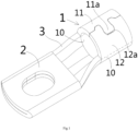
- Figure 1 shows an illustrative perspective view of a connection terminal according to an exemplary embodiment of the present invention, wherein the base part 10 of the crimping part 1 of the connection terminal is marked with dashed lines;
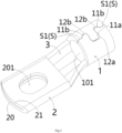
- Figure 2 shows an illustrative perspective view of a connection terminal according to an exemplary embodiment of the present invention, in which the mating structure of the splicing parts 11 and 12 of the crimping part 1 of the connection terminal is detailed;
- Figure 3 shows an illustrative perspective view of a connection terminal according to an exemplary embodiment of the present invention when viewed from one direction.
- connection terminal includes a crimping part 1, which is adapted to be crimped onto a first conductor (not shown), for example, it can be crimped onto an exposed conductor core of a cable.
- the crimping part 1 includes a semi cylindrical base part 10 and two splicing parts 11 and 12.
- the two splicing parts 11 and 12 extend continuously from both sides of the semi cylindrical base part 10 in a circumferential direction and are engaged to each other, resulting in a complete cylindrical shape of the crimping part 1.
- a buckle structure 11a and 12a is formed on the two splicing parts 11 and 12 to lock them together, to ensure that the two splicing parts 11 and 12 cannot be separated when the crimping part 1 is crimped onto the first conductor.
- the buckle structure 11a and 12a includes a buckle 11a and a snap slot 12a.
- the buckle 11a is formed on one splicing part 11 and protrudes towards the other splicing part 12 in a circumferential direction of the crimping part 1.
- the snap slot 12a is formed on the other splicing part 12.
- the shape and size of the snap slot 12a are complementary to the shape and size of the buckle 11a.
- the buckle 11a and the snap slot 12a are mated together in a radial direction of the crimping part 1 and cannot be separated in any direction other than the radial direction. Therefore, when crimping the crimping part 1 onto the first conductor, the two splicing parts 11 and 12 will not separate.
- the buckle 11a has a root and an end, and the root of the buckle 11a is narrower than the end of the buckle 11a.
- the snap slot 12a has an opening and an interior that are mated with the root and the end of the buckle 11a, and the opening of the snap slot 12a is narrower than the interior of the snap slot.
- the buckle 11a is in a dovetail shape with a narrower root and a wider end, while the snap slot 12a is in a dovetail shape with a narrower opening and a wider interior.
- the present invention is not limited to the illustrated embodiment.
- the root of the buckle 11a and the opening of the snap slot 12a are rectangular, and the end of the buckle 11a and the interior of the snap slot 12a are fan-shaped with a Central angle greater than 180 degrees and less than 360 degrees. This ⁇ shaped buckle 11a and snap slot 12a can also ensure a good fit.
- the buckle 11a and the snap slot 12a can be in a curved hook shape, so that when the buckle 11a and the snap slot 12a are mated together, the buckle 11a and the snap slot 12a cannot be separated in any direction other than the radial direction.
- This hook shaped buckle 11a and snap slot 12a can also ensure a good fit.
- a pair of concave parts 11b are also formed on one of the splicing parts 11, and the pair of concave parts 11b are respectively located at both sides of the root of the buckle 11a.
- a pair of convex parts 12b are also formed on the other splicing part 12, and the pair of convex parts 12b are respectively located at both sides of the opening of the snap slot 12a.
- the shape and size of the convex part 12b are complementary to the shape and size of the concave part 11b.
- the convex part 12b and the concave part 11b cooperate with each other to prevent the two splicing parts 11 and 12 from being misaligned in an axial direction of the crimping part 1. This can prevent the two splicing parts 11 and 12 from moving relative to each other in the axial direction.
- the pair of concave parts 11b are symmetrically arranged at both sides of the root of the buckle 11a, and the pair of convex parts 12b are symmetrically arranged at both sides of the opening of the snap slot 12a. Symmetrical structure can ensure uniform stress and better mechanical strength.
- the concave part 11b is a trapezoidal shape with a wider opening and a narrower interior
- the convex part 12b is a trapezoidal shape with a wider root and a narrower end.
- the present invention is not limited to the illustrated embodiments, and the concave portion 11b and the convex portion 12b may also have other suitable shapes.
- the splicing seam S between the two splicing parts 11 and 12 includes two straight seams S1 and a curved splicing seam located between the two straight seams S1.
- Two straight seams S1 are located at both axial ends of the crimping part 1 and extend along the axial direction of the crimping part 1.
- the curved splicing seam is located between two straight seams S1 and extends along a curved path.
- the curved splicing seam is defined by the outer contour of the mated buckle 11a and snap slot 12a, as well as the mated concave part 11b and convex part 12b.
- connection terminal further includes a connection end 2, which is suitable for being fastened to a second conductor (not shown) through a fastener, for example, to one end of a charging terminal of a charging seat.
- connection end 2 is flat and is formed with a connection hole 201 to allow the fastener to pass through.
- connection end 2 is fastened to the second conductor, the surface of the connection end 2 is in electrical contact with the surface of the second conductor.
- the longitudinal size of the connection hole 201 in the longitudinal direction of the connection terminal is greater than the transverse size of the connection hole 201 in the transverse direction of the connection terminal, enabling the position of the fastener to be adjusted in the longitudinal direction. This allows for a certain manufacturing error in the size of the connection terminal.
- connection hole 201 of the connection end 2 and the central axis of the central through hole 101 of the crimping part 1 are in the same plane perpendicular to the transverse direction of the connection terminal. This can shorten the length of the path through which the current flows.
- connection end 2 includes a bottom layer plate 20 and a top layer plate 21 overlapped on the bottom layer plate 20, so that the thickness of the connection end 2 is greater than the thickness of the rest part of the connection terminal.
- connection end 2 of the connection terminal is a double-layer plate structure, and the rest part of the connection terminal is a single-layer plate structure.
- one end of the bottom layer plate 20 of the connection end 2 is connected to one end of the base part 10 of the crimping part 1, and one side of the bottom layer plate 20 of the connection end 2 is connected to one side of the top layer plate 21 of the connection end 2.
- connection terminal further includes a connecting part 3, which is connected between one end of the base part 10 of the crimping part 1 and one end of the bottom layer plate 20 of the connection end 2.
- connection terminal is an integral stamping formed terminal.
- the connection terminal can be made by stamping a single metal sheet.
- Figure 4 shows an illustrative perspective view of a connection terminal according to another exemplary embodiment of the present invention.
- connection terminal shown in Figure 4 The difference between the connection terminal shown in Figure 4 and the connection terminal shown in Figures 1-3 is only in the structure of the connection end 2.
- connection end 2 includes a single layer plate, so that the thickness of the connection end 2 is equal to the thickness of the rest part of the connection terminal.
- the connection end 2 may include a single-layer thickened plate, so that the thickness of the connection end 2 is greater than the thickness of the rest part of the connection terminal.
- a cable assembly which includes a cable and the aforementioned connection terminal.
- the exposed conductor core of the cable is inserted into the central through hole 101 of the crimping part 1 of the connection terminal, and the crimping part 1 of the connection terminal is crimped onto the exposed conductor core of the cable.
- a charging seat which includes a housing, a charging terminal, and the aforementioned cable assembly.
- the charging terminal is installed in the housing.
- One end of the charging terminal is fastened to the connection terminal 2 of the cable assembly through a fastener.
Landscapes
- Engineering & Computer Science (AREA)
- Manufacturing & Machinery (AREA)
- Connections Effected By Soldering, Adhesion, Or Permanent Deformation (AREA)
- Insulated Conductors (AREA)
Abstract
Description
- This application claims the benefit of Chinese Patent Application No.
CN202221216825.3 filed on May 20, 2022 - The present invention relates to a connection terminal, a cable assembly including the connection terminal, and a charging seat including the cable assembly.
- In prior art, the charging seat on a new energy vehicle needs to be electrically connected to the power supply through a cable assembly. The cable assembly typically includes a cable and a connection terminal. The connection terminal has a crimping part, which is crimped onto the exposed conductor core at the end of the cable.
- In prior art, the crimping part of the connection terminal usually includes a U-shaped base and a pair of side wings extending from both sides of the U-shaped base. During crimping, the conductor core of the cable is positioned in the U-shaped base, and the pair of side wings are bent and squeezed onto the conductor core to achieve electrical connection between the connection terminal and the cable.
- However, the existing crimping part has poor conductivity and mechanical property after being crimped onto the conductor core, such as high contact resistance, poor current carrying capacity, and easy loosening.
- The present invention has been made to overcome or alleviate at least one aspect of the above mentioned disadvantages.
- According to an aspect of the present invention, there is provided a connection terminal. The connection terminal comprises of a crimping part which is adapted to be crimped onto a first conductor; and a connection end which is adapted to be electrically connected to a second conductor and is connected to the crimping part to form an integral piece with the crimping part. The crimping part comprises of a base part; and two splicing parts extending continuously from both sides of the base part. When the crimping part is bent to form a cylindrical shape, the two splicing parts are spliced together to form a complete cylindrical shape. A buckle structure is formed on the two splicing parts to lock the two together, to ensure that the two splicing parts will not separate when the crimping part is crimped onto the first conductor.
- According to an exemplary embodiment of the present invention, the buckle structure comprises of a buckle formed on one splicing part and protruding towards the other splicing part along a circumferential direction of the crimping part; and a snap slot formed on the other splicing part. The shape and size of the snap slot are complementary to the shape and size of the buckle, and the buckle and the snap slot are mated together in a radial direction of the crimping part and cannot be separated in any direction other than the radial direction.
- According to another exemplary embodiment of the present invention, the buckle has a root and an end, and the root of the buckle is narrower than the end of the buckle, the snap slot has an opening and an interior that are respectively mated with the root and the end of the buckle, and the opening of the snap slot is narrower than the interior of the snap slot; when the buckle and the snap slot are mated together, the larger end of the buckle cannot be pulled out from the smaller opening of the snap slot, so that the buckle and the snap slot cannot separate in any direction other than the radial direction.
- According to another exemplary embodiment of the present invention, the buckle is in a dovetail shape with a narrower root and a wider end, and the snap slot is in a dovetail shape with a narrower opening and a wider interior.
- According to another exemplary embodiment of the present invention, the root of the buckle and the opening of the snap slot are rectangular, and the end of the buckle and the interior of the snap slot are fan-shaped with a Central angle greater than 180 degrees and less than 360 degrees.
- According to another exemplary embodiment of the present invention, the buckle and the snap slot are in a curved hook shape, so that when the buckle and the snap slot are mated together, the buckle and the snap slot cannot separate in any direction other than the radial direction.
- According to another exemplary embodiment of the present invention, a pair of concave parts are also formed on one splicing part, and the pair of concave parts are respectively located at both sides of the root of the buckle; a pair of convex parts are formed on the other splicing part, and the pair of convex parts are respectively located at both sides of the opening of the snap slot; the shape and size of the convex part are complementary to the shape and size of the concave part, and the convex part and the concave part cooperate with each other to prevent the two splicing parts from being misaligned axially.
- According to another exemplary embodiment of the present invention, the pair of concave parts are symmetrically arranged at both sides of the root of the buckle, and the pair of convex parts are symmetrically arranged at both sides of the opening of the snap slot.
- According to another exemplary embodiment of the present invention, the concave part is a trapezoidal shape with a wider opening and a narrower interior, and the convex part is a trapezoidal shape with a wider root and a narrower end.
- According to another exemplary embodiment of the present invention, the splicing seam between the two splicing parts comprises of: two straight splicing seams which are respectively located at both axial ends of the crimping part and extend along the axial direction of the crimping part; and a curved splicing seam located between the two straight splicing seams and extending along a curved path. The curved splicing seam is defined by the outer contour of the mated buckle and snap slot as well as the mated convex part and the concave part.
- According to another exemplary embodiment of the present invention, the connection end is adapted to be fastened to the second conductor by a fastener.
- According to another exemplary embodiment of the present invention, the connection end is flat and is formed with a connection hole to allow the fastener to pass through, when the connection end is fastened to the second conductor, the surface of the connection end is in electrical contact with the surface of the second conductor.
- According to another exemplary embodiment of the present invention, a longitudinal size of the connection hole in a longitudinal direction of the connection terminal is greater than a transverse size of the connection hole in a transverse direction of the connection terminal, so that the position of the fastener in the longitudinal direction can be adjusted.
- According to another exemplary embodiment of the present invention, a longitudinal symmetrical axis of the connection hole on the connection end and a central axis of a central through hole of the crimping part are in the same plane perpendicular to the transverse direction of the connection terminal.
- According to another exemplary embodiment of the present invention, the connection end includes a bottom layer plate and a top layer plate overlapped on the bottom layer plate, so that the thickness of the connection end is greater than the thickness of the rest part of the connection terminal; one end of the bottom layer plate of the connection end is connected to one end of the base part of the crimping part, and one side of the bottom layer plate of the connection end is connected to one side of the top layer plate of the connection end.
- According to another exemplary embodiment of the present invention, the connection end includes a single layer plate, so that the thickness of the connection end is equal to the thickness of the rest part of the connection terminal; or the connection end includes a single layer thickened plate, so that the thickness of the connection end is greater than the thickness of the rest part of the connection terminal.
- According to another exemplary embodiment of the present invention, the connection terminal further comprises of a connecting part which is connected between one end of the base part of the crimping part and one end of the connection end.
- According to another exemplary embodiment of the present invention, the connection terminal is an integral stamping formed terminal.
- According to another aspect of the present invention, there is provided a cable assembly. The cable assembly comprises of a cable; and the above connection terminal. An exposed conductor core of the cable is inserted into a central through hole of the crimping part of the connection terminal, and the crimping part of the connection terminal is crimped onto the exposed conductor core of the cable.
- According to another aspect of the present invention, there is provided a charging seat. The charging seat comprises of: a housing; a charging terminal installed in the housing; and the above cable assembly. One end of the charging terminal is fastened to the connection end of the connection terminal by a fastener.
- In the aforementioned exemplary embodiments of the present invention, the cylindrical crimping part can reduce contact resistance, improve current carrying capacity, and ensure the reliability of mechanical connection, greatly improving the conductivity and mechanical performance of the crimping part.
- The above and other features of the present invention will become more apparent by describing in detail exemplary embodiments thereof with reference to the accompanying drawings, in which:
-
Figure 1 shows an illustrative perspective view of a connection terminal according to an exemplary embodiment of the present invention, wherein the base part of the crimping part of the connection terminal is marked with dashed lines; -
Figure 2 shows an illustrative perspective view of a connection terminal according to an exemplary embodiment of the present invention; -
Figure 3 shows an illustrative perspective view of a connection terminal according to an exemplary embodiment of the present invention when viewed from one direction; and -
Figure 4 shows an illustrative perspective view of a connection terminal according to another exemplary embodiment of the present invention. - Exemplary embodiments of the present disclosure will be described hereinafter in detail with reference to the attached drawings, wherein the like reference numerals refer to the like elements. The present disclosure may, however, be embodied in many different forms and should not be construed as being limited to the embodiment set forth herein; rather, these embodiments are provided so that the present disclosure will be thorough and complete, and will fully convey the concept of the disclosure to those skilled in the art.
- In the following detailed description, for purposes of explanation, numerous specific details are set forth in order to provide a thorough understanding of the disclosed embodiments. It will be apparent, however, that one or more embodiments may be practiced without these specific details. In other instances, well-known structures and devices are schematically shown in order to simplify the drawing.
- According to an overall technical concept of the present invention, a connection terminal is provided. The connection terminal comprises of: a
crimping part 1 which is adapted to be crimped onto a first conductor; and aconnection end 2 which is adapted to be electrically connected to a second conductor and is connected to the crimpingpart 1 to form an integral piece with the crimpingpart 1. The crimpingpart 1 comprises of: abase part 10; and twosplicing parts base part 10. When the crimpingpart 1 is bent to form a cylindrical shape, the two splicingparts buckle structure splicing parts splicing parts part 1 is crimped onto the first conductor. -
Figure 1 shows an illustrative perspective view of a connection terminal according to an exemplary embodiment of the present invention, wherein thebase part 10 of the crimpingpart 1 of the connection terminal is marked with dashed lines;Figure 2 shows an illustrative perspective view of a connection terminal according to an exemplary embodiment of the present invention, in which the mating structure of thesplicing parts part 1 of the connection terminal is detailed;Figure 3 shows an illustrative perspective view of a connection terminal according to an exemplary embodiment of the present invention when viewed from one direction. - As shown in
Figures 1 to 3 , in the illustrated embodiments, the connection terminal includes acrimping part 1, which is adapted to be crimped onto a first conductor (not shown), for example, it can be crimped onto an exposed conductor core of a cable. - As shown in
Figures 1 to 3 , in the illustrated embodiment, the crimpingpart 1 includes a semicylindrical base part 10 and twosplicing parts splicing parts cylindrical base part 10 in a circumferential direction and are engaged to each other, resulting in a complete cylindrical shape of the crimpingpart 1. - As shown in
Figures 1 to 3 , in the illustrated embodiments, abuckle structure splicing parts splicing parts part 1 is crimped onto the first conductor. - As shown in
Figures 1 to 3 , in the illustrated embodiments, thebuckle structure buckle 11a and asnap slot 12a. Thebuckle 11a is formed on onesplicing part 11 and protrudes towards theother splicing part 12 in a circumferential direction of the crimpingpart 1. Thesnap slot 12a is formed on theother splicing part 12. The shape and size of thesnap slot 12a are complementary to the shape and size of thebuckle 11a. - As shown in
Figures 1 to 3 , in the illustrated embodiments, thebuckle 11a and thesnap slot 12a are mated together in a radial direction of the crimpingpart 1 and cannot be separated in any direction other than the radial direction. Therefore, when crimping the crimpingpart 1 onto the first conductor, the twosplicing parts - As shown in
Figures 1 to 3 , in the illustrated embodiments, thebuckle 11a has a root and an end, and the root of thebuckle 11a is narrower than the end of thebuckle 11a. Thesnap slot 12a has an opening and an interior that are mated with the root and the end of thebuckle 11a, and the opening of thesnap slot 12a is narrower than the interior of the snap slot. - As shown in
Figures 1 to 3 , in the illustrated embodiments, when thebuckle 11a and thesnap slot 12a are mated together, the larger end of thebuckle 11a cannot be pulled out from the smaller opening of thesnap slot 12a, so that thebuckle 11a and thesnap slot 12a cannot be separated in any direction other than the radial direction. - As shown in
Figures 1 to 3 , in the illustrated embodiments, thebuckle 11a is in a dovetail shape with a narrower root and a wider end, while thesnap slot 12a is in a dovetail shape with a narrower opening and a wider interior. - However, please note that the present invention is not limited to the illustrated embodiment. For example, in another exemplary embodiment of the present invention, the root of the
buckle 11a and the opening of thesnap slot 12a are rectangular, and the end of thebuckle 11a and the interior of thesnap slot 12a are fan-shaped with a Central angle greater than 180 degrees and less than 360 degrees. This Ω shapedbuckle 11a andsnap slot 12a can also ensure a good fit. - Although not shown, in another exemplary embodiment of the present invention, the
buckle 11a and thesnap slot 12a can be in a curved hook shape, so that when thebuckle 11a and thesnap slot 12a are mated together, thebuckle 11a and thesnap slot 12a cannot be separated in any direction other than the radial direction. This hook shapedbuckle 11a andsnap slot 12a can also ensure a good fit. - As shown in
Figures 1 to 3 , in the illustrated embodiment, a pair ofconcave parts 11b are also formed on one of thesplicing parts 11, and the pair ofconcave parts 11b are respectively located at both sides of the root of thebuckle 11a. A pair ofconvex parts 12b are also formed on theother splicing part 12, and the pair ofconvex parts 12b are respectively located at both sides of the opening of thesnap slot 12a. The shape and size of theconvex part 12b are complementary to the shape and size of theconcave part 11b. Theconvex part 12b and theconcave part 11b cooperate with each other to prevent the twosplicing parts part 1. This can prevent the twosplicing parts - As shown in
Figures 1 to 3 , in the illustrated embodiments, the pair ofconcave parts 11b are symmetrically arranged at both sides of the root of thebuckle 11a, and the pair ofconvex parts 12b are symmetrically arranged at both sides of the opening of thesnap slot 12a. Symmetrical structure can ensure uniform stress and better mechanical strength. - As shown in
Figures 1 to 3 , in the illustrated embodiments, theconcave part 11b is a trapezoidal shape with a wider opening and a narrower interior, while theconvex part 12b is a trapezoidal shape with a wider root and a narrower end. However, the present invention is not limited to the illustrated embodiments, and theconcave portion 11b and theconvex portion 12b may also have other suitable shapes. - As shown in
Figures 1 to 3 , in the illustrated embodiment, the splicing seam S between the twosplicing parts part 1 and extend along the axial direction of the crimpingpart 1. The curved splicing seam is located between two straight seams S1 and extends along a curved path. In the illustrated embodiment, the curved splicing seam is defined by the outer contour of the matedbuckle 11a andsnap slot 12a, as well as the matedconcave part 11b andconvex part 12b. - As shown in
Figures 1 to 3 , in the illustrated embodiments, the connection terminal further includes aconnection end 2, which is suitable for being fastened to a second conductor (not shown) through a fastener, for example, to one end of a charging terminal of a charging seat. - As shown in
Figures 1 to 3 , in the illustrated embodiment, theconnection end 2 is flat and is formed with aconnection hole 201 to allow the fastener to pass through. When theconnection end 2 is fastened to the second conductor, the surface of theconnection end 2 is in electrical contact with the surface of the second conductor. - As shown in
Figures 1 to 3 , in the illustrated embodiments, the longitudinal size of theconnection hole 201 in the longitudinal direction of the connection terminal is greater than the transverse size of theconnection hole 201 in the transverse direction of the connection terminal, enabling the position of the fastener to be adjusted in the longitudinal direction. This allows for a certain manufacturing error in the size of the connection terminal. - As shown in
Figures 1 to 3 , in the illustrated embodiments, the longitudinal symmetrical axis of theconnection hole 201 of theconnection end 2 and the central axis of the central throughhole 101 of the crimpingpart 1 are in the same plane perpendicular to the transverse direction of the connection terminal. This can shorten the length of the path through which the current flows. - As shown in
Figures 1 to 3 , in the illustrated embodiments, theconnection end 2 includes abottom layer plate 20 and atop layer plate 21 overlapped on thebottom layer plate 20, so that the thickness of theconnection end 2 is greater than the thickness of the rest part of the connection terminal. In the illustrated embodiment, theconnection end 2 of the connection terminal is a double-layer plate structure, and the rest part of the connection terminal is a single-layer plate structure. - As shown in
Figures 1 to 3 , in the illustrated embodiments, one end of thebottom layer plate 20 of theconnection end 2 is connected to one end of thebase part 10 of the crimpingpart 1, and one side of thebottom layer plate 20 of theconnection end 2 is connected to one side of thetop layer plate 21 of theconnection end 2. - As shown in
Figures 1 to 3 , in the illustrated embodiments, the connection terminal further includes a connectingpart 3, which is connected between one end of thebase part 10 of the crimpingpart 1 and one end of thebottom layer plate 20 of theconnection end 2. - As shown in
Figures 1 to 3 , in the illustrated embodiment, the connection terminal is an integral stamping formed terminal. For example, the connection terminal can be made by stamping a single metal sheet. -
Figure 4 shows an illustrative perspective view of a connection terminal according to another exemplary embodiment of the present invention. - The difference between the connection terminal shown in
Figure 4 and the connection terminal shown inFigures 1-3 is only in the structure of theconnection end 2. - As shown in
Figure 4 , in the illustrated embodiment, theconnection end 2 includes a single layer plate, so that the thickness of theconnection end 2 is equal to the thickness of the rest part of the connection terminal. However, the present invention is not limited to this. For example, in another exemplary embodiment of the present invention, theconnection end 2 may include a single-layer thickened plate, so that the thickness of theconnection end 2 is greater than the thickness of the rest part of the connection terminal. - Although not shown, in another exemplary embodiment of the present invention, a cable assembly is also disclosed, which includes a cable and the aforementioned connection terminal. The exposed conductor core of the cable is inserted into the central through
hole 101 of the crimpingpart 1 of the connection terminal, and the crimpingpart 1 of the connection terminal is crimped onto the exposed conductor core of the cable. - Although not shown, in another exemplary embodiment of the present invention, a charging seat is also disclosed, which includes a housing, a charging terminal, and the aforementioned cable assembly. The charging terminal is installed in the housing. One end of the charging terminal is fastened to the
connection terminal 2 of the cable assembly through a fastener. - It should be appreciated for those skilled in this art that the above embodiments are intended to be illustrated, and not restrictive. For example, many modifications may be made to the above embodiments by those skilled in this art, and various features described in different embodiments may be freely combined with each other without conflicting in configuration or principle.
- Although several exemplary embodiments have been shown and described, it would be appreciated by those skilled in the art that various changes or modifications may be made in these embodiments without departing from the principles and spirit of the disclosure, the scope of which is defined in the claims and their equivalents.
- As used herein, an element recited in the singular and proceeded with the word "a" or "an" should be understood as not excluding plural of said elements or steps, unless such exclusion is explicitly stated. Furthermore, references to "one embodiment" of the present invention are not intended to be interpreted as excluding the existence of additional embodiments that also incorporate the recited features. Moreover, unless explicitly stated to the contrary, embodiments "comprising" or "having" an element or a plurality of elements having a particular property may include additional such elements not having that property.
Claims (15)
- A connection terminal, characterized by comprising:a crimping part (1) which is adapted to be crimped onto a first conductor; anda connection end (2) which is adapted to be electrically connected to a second conductor and is connected to the crimping part (1) to form an integral piece with the crimping part (1),wherein the crimping part (1) comprises ofa base part (10); andtwo splicing parts (11, 12) extending continuously from both sides of the base part (10),wherein when the crimping part (1) is bent to form a cylindrical shape, the two splicing parts (11, 12) are spliced together to form a complete cylindrical shape,wherein a buckle structure (11a, 12a) is formed on the two splicing parts (11, 12) to lock the two together, to ensure that the two splicing parts (11, 12) will not separate when the crimping part (1) is crimped onto the first conductor.
- The connection terminal according to claim 1, characterized in that the buckle structure (11a, 12a) comprises of:a buckle (11a) formed on one splicing part (11) and protruding towards the other splicing part (12) along a circumferential direction of the crimping part (1); anda snap slot (12a) formed on the other splicing part (12),
the shape and size of the snap slot (12a) are complementary to the shape and size of the buckle (11a), and the buckle (11a) and the snap slot (12a) are mated together in a radial direction of the crimping part (1) and cannot be separated in any direction other than the radial direction. - The connection terminal according to claim 2, characterized in thatthe buckle (11a) has a root and an end, and the root of the buckle (11a) is narrower than the end of the buckle (11a), the snap slot (12a) has an opening and an interior that are respectively mated with the root and the end of the buckle (11a), and the opening of the snap slot (12a) is narrower than the interior of the snap slot (12a);when the buckle (11a) and the snap slot (12a) are mated together, the larger end of the buckle (11a) cannot be pulled out from the smaller opening of the snap slot (12a), so that the buckle (11a) and the snap slot (12a) cannot separate in any direction other than the radial direction.
- The connection terminal according to claim 3, characterized in thatthe buckle (11a) is in a dovetail shape with a narrower root and a wider end, and the snap slot (12a) is in a dovetail shape with a narrower opening and a wider interior; orthe root of the buckle (11a) and the opening of the snap slot (12a) are rectangular, and the end of the buckle (11a) and the interior of the snap slot (12a) are fan-shaped with a Central angle greater than 180 degrees and less than 360 degrees; orthe buckle (11a) and the snap slot (12a) are in a curved hook shape, so that when the buckle (11a) and the snap slot (12a) are mated together, the buckle (11a) and the snap slot (12a) cannot separate in any direction other than the radial direction.
- The connection terminal according to claim 3, characterized in thata pair of concave parts (11b) are also formed on one splicing part (11), and the pair of concave parts (11b) are respectively located at both sides of the root of the buckle (11a);a pair of convex parts (12b) are formed on the other splicing part (12), and the pair of convex parts (12b) are respectively located at both sides of the opening of the snap slot (12a);the shape and size of the convex part (12b) are complementary to the shape and size of the concave part (11b), and the convex part (12b) and the concave part (11b) cooperate with each other to prevent the two splicing parts (11, 12) from being misaligned axially.
- The connection terminal according to claim 5, characterized in thatthe pair of concave parts (11b) are symmetrically arranged at both sides of the root of the buckle (11a), and the pair of convex parts (12b) are symmetrically arranged at both sides of the opening of the snap slot (12a);the concave part (11b) is a trapezoidal shape with a wider opening and a narrower interior, and the convex part (12b) is a trapezoidal shape with a wider root and a narrower end.
- The connection terminal according to claim 5, characterized in that the splicing seam (S) between the two splicing parts (11, 12) comprises of:two straight splicing seams (S1) which are respectively located at both axial ends of the crimping part (1) and extend along the axial direction of the crimping part (1); anda curved splicing seam located between the two straight splicing seams (S1) and extending along a curved path,
the curved splicing seam is defined by the outer contour of the mated buckle (11a) and snap slot (12a) as well as the mated convex part (11b) and the concave part (12b). - The connection terminal according to claim 1, characterized in thatthe connection end (2) is adapted to be fastened to the second conductor by a fastener;the connection end (2) is flat and is formed with a connection hole (201) to allow the fastener to pass through,when the connection end (2) is fastened to the second conductor, the surface of the connection end (2) is in electrical contact with the surface of the second conductor.
- The connection terminal according to claim 8, characterized in thata longitudinal size of the connection hole (201) in a longitudinal direction of the connection terminal is greater than a transverse size of the connection hole (201) in a transverse direction of the connection terminal, so that the position of the fastener in the longitudinal direction can be adjusted;a longitudinal symmetrical axis of the connection hole (201) on the connection end (2) and a central axis of a central through hole (101) of the crimping part (1) are in the same plane perpendicular to the transverse direction of the connection terminal.
- The connection terminal according to claim 8, characterized in thatthe connection end (2) includes a bottom layer plate (20) and a top layer plate (21) overlapped on the bottom layer plate (20), so that the thickness of the connection end (2) is greater than the thickness of the rest part of the connection terminal;one end of the bottom layer plate (20) of the connection end (2) is connected to one end of the base part (10) of the crimping part (1), and one side of the bottom layer plate (20) of the connection end (2) is connected to one side of the top layer plate (21) of the connection end (2).
- The connection terminal according to claim 8, characterized in thatthe connection end (2) includes a single layer plate, so that the thickness of the connection end (2) is equal to the thickness of the rest part of the connection terminal; orthe connection end (2) includes a single layer thickened plate, so that the thickness of the connection end (2) is greater than the thickness of the rest part of the connection terminal.
- The connection terminal according to claim 8, characterized by further comprising:
a connecting part (3) which is connected between one end of the base part (10) of the crimping part (1) and one end of the connection end (2). - The connection terminal according to any one of claims 1-12, characterized in that the connection terminal is an integral stamping formed terminal.
- A cable assembly, characterized by comprising:a cable; andthe connection terminal according to any one of claims 1-13,wherein an exposed conductor core of the cable is inserted into a central through hole (101) of the crimping part (1) of the connection terminal, and the crimping part (1) of the connection terminal is crimped onto the exposed conductor core of the cable.
- A charging seat, characterized by comprising:a housing;a charging terminal installed in the housing; andthe cable assembly as claimed in claim 14,wherein one end of the charging terminal is fastened to the connection end (2) of the connection terminal by a fastener.
Applications Claiming Priority (1)
| Application Number | Priority Date | Filing Date | Title |
|---|---|---|---|
| CN202221216825.3U CN217444645U (en) | 2022-05-20 | 2022-05-20 | Connecting terminal, cable subassembly and charging seat |
Publications (1)
| Publication Number | Publication Date |
|---|---|
| EP4280385A1 true EP4280385A1 (en) | 2023-11-22 |
Family
ID=83222538
Family Applications (1)
| Application Number | Title | Priority Date | Filing Date |
|---|---|---|---|
| EP23173803.0A Pending EP4280385A1 (en) | 2022-05-20 | 2023-05-17 | Connection terminal, cable assembly and charging seat |
Country Status (4)
| Country | Link |
|---|---|
| EP (1) | EP4280385A1 (en) |
| JP (1) | JP2023171317A (en) |
| KR (1) | KR20230162559A (en) |
| CN (1) | CN217444645U (en) |
Citations (4)
| Publication number | Priority date | Publication date | Assignee | Title |
|---|---|---|---|---|
| US4692122A (en) * | 1986-10-06 | 1987-09-08 | Minnesota Mining And Manufacturing Company | Electrical terminal |
| CH675930A5 (en) * | 1988-06-16 | 1990-11-15 | Rutschmann Ag | Heavy current cable connector - has terminal with elongated slot and captive nut for ease of fixing to cable shoe |
| US20070066148A1 (en) * | 2005-09-16 | 2007-03-22 | Gebauer & Griller Kabelwerke Gesellschaft M.B.H. | Connecting terminal |
| DE102011017071A1 (en) * | 2011-04-14 | 2012-10-18 | Auto-Kabel Managementgesellschaft Mbh | Connector for electrical system of e.g. motor vehicle, has sleeve provided for receiving cable, and included with flat portion having rectangular region and circular region formed in distal ends |
-
2022
- 2022-05-20 CN CN202221216825.3U patent/CN217444645U/en active Active
-
2023
- 2023-05-17 JP JP2023081297A patent/JP2023171317A/en active Pending
- 2023-05-17 EP EP23173803.0A patent/EP4280385A1/en active Pending
- 2023-05-19 KR KR1020230065045A patent/KR20230162559A/en active Pending
Patent Citations (4)
| Publication number | Priority date | Publication date | Assignee | Title |
|---|---|---|---|---|
| US4692122A (en) * | 1986-10-06 | 1987-09-08 | Minnesota Mining And Manufacturing Company | Electrical terminal |
| CH675930A5 (en) * | 1988-06-16 | 1990-11-15 | Rutschmann Ag | Heavy current cable connector - has terminal with elongated slot and captive nut for ease of fixing to cable shoe |
| US20070066148A1 (en) * | 2005-09-16 | 2007-03-22 | Gebauer & Griller Kabelwerke Gesellschaft M.B.H. | Connecting terminal |
| DE102011017071A1 (en) * | 2011-04-14 | 2012-10-18 | Auto-Kabel Managementgesellschaft Mbh | Connector for electrical system of e.g. motor vehicle, has sleeve provided for receiving cable, and included with flat portion having rectangular region and circular region formed in distal ends |
Also Published As
| Publication number | Publication date |
|---|---|
| JP2023171317A (en) | 2023-12-01 |
| KR20230162559A (en) | 2023-11-28 |
| CN217444645U (en) | 2022-09-16 |
Similar Documents
| Publication | Publication Date | Title |
|---|---|---|
| EP2019459B1 (en) | High performance coaxial connector | |
| CN102405561B (en) | Terminal fitting and method for assembling said terminal fitting | |
| US20120156947A1 (en) | Receptacle terminal | |
| JP5579213B2 (en) | Female terminal and connection structure | |
| JP2018026323A (en) | Radio frequency coaxial connector assembly and method of manufacturing the assembly | |
| CN103620875A (en) | Electrical terminal and receptacle assembly | |
| JPH09223532A (en) | Male terminal | |
| JP2561894B2 (en) | Electrical terminals for mating blade contacts | |
| EP3467949B1 (en) | High-current electrical connector | |
| EP1798820A1 (en) | Electrical contact | |
| EP2606536B1 (en) | Electrical male terminal | |
| CN114122803B (en) | Wire harness connector | |
| US20100055998A1 (en) | Terminal fitting and a wire connected with a terminal fitting | |
| EP3644449B1 (en) | Connection assembly and connection method | |
| US8506336B2 (en) | Stamped and formed contact | |
| US12470000B2 (en) | Male terminal including opening and projecting portion | |
| US20250233335A1 (en) | Connector Terminal and Connector | |
| US11837825B2 (en) | Connector for bus bar plug assembly | |
| EP4539258A1 (en) | Connector terminal, connector, and method for manufacturing connector terminal | |
| CN219626933U (en) | High-voltage connector terminal, high-voltage connector cable assembly and high-voltage connector | |
| KR20230162559A (en) | Connection terminal, cable assembly and charging seat | |
| US20240305050A1 (en) | Female terminal and manufacturing method of such a terminal | |
| US11862882B2 (en) | Tubular high current female terminal | |
| EP4254680B1 (en) | Shielded connection assembly, connector for this connection assembly and method of manufacturing a shielding element for this connection assembly | |
| CN218849868U (en) | Jack contact piece and conductive assembly |
Legal Events
| Date | Code | Title | Description |
|---|---|---|---|
| PUAI | Public reference made under article 153(3) epc to a published international application that has entered the european phase |
Free format text: ORIGINAL CODE: 0009012 |
|
| STAA | Information on the status of an ep patent application or granted ep patent |
Free format text: STATUS: THE APPLICATION HAS BEEN PUBLISHED |
|
| AK | Designated contracting states |
Kind code of ref document: A1 Designated state(s): AL AT BE BG CH CY CZ DE DK EE ES FI FR GB GR HR HU IE IS IT LI LT LU LV MC ME MK MT NL NO PL PT RO RS SE SI SK SM TR |
|
| STAA | Information on the status of an ep patent application or granted ep patent |
Free format text: STATUS: REQUEST FOR EXAMINATION WAS MADE |
|
| 17P | Request for examination filed |
Effective date: 20240415 |
|
| RBV | Designated contracting states (corrected) |
Designated state(s): AL AT BE BG CH CY CZ DE DK EE ES FI FR GB GR HR HU IE IS IT LI LT LU LV MC ME MK MT NL NO PL PT RO RS SE SI SK SM TR |
|
| STAA | Information on the status of an ep patent application or granted ep patent |
Free format text: STATUS: EXAMINATION IS IN PROGRESS |
|
| 17Q | First examination report despatched |
Effective date: 20251015 |