EP4280368A1 - Battery cell, battery and electric device - Google Patents
Battery cell, battery and electric device Download PDFInfo
- Publication number
- EP4280368A1 EP4280368A1 EP22919278.6A EP22919278A EP4280368A1 EP 4280368 A1 EP4280368 A1 EP 4280368A1 EP 22919278 A EP22919278 A EP 22919278A EP 4280368 A1 EP4280368 A1 EP 4280368A1
- Authority
- EP
- European Patent Office
- Prior art keywords
- connector
- battery
- stepped surface
- pin
- battery cell
- Prior art date
- Legal status (The legal status is an assumption and is not a legal conclusion. Google has not performed a legal analysis and makes no representation as to the accuracy of the status listed.)
- Pending
Links
Images



Classifications
-
- H—ELECTRICITY
- H01—ELECTRIC ELEMENTS
- H01M—PROCESSES OR MEANS, e.g. BATTERIES, FOR THE DIRECT CONVERSION OF CHEMICAL ENERGY INTO ELECTRICAL ENERGY
- H01M50/00—Constructional details or processes of manufacture of the non-active parts of electrochemical cells other than fuel cells, e.g. hybrid cells
- H01M50/50—Current conducting connections for cells or batteries
- H01M50/543—Terminals
- H01M50/552—Terminals characterised by their shape
- H01M50/553—Terminals adapted for prismatic, pouch or rectangular cells
-
- H—ELECTRICITY
- H01—ELECTRIC ELEMENTS
- H01M—PROCESSES OR MEANS, e.g. BATTERIES, FOR THE DIRECT CONVERSION OF CHEMICAL ENERGY INTO ELECTRICAL ENERGY
- H01M50/00—Constructional details or processes of manufacture of the non-active parts of electrochemical cells other than fuel cells, e.g. hybrid cells
- H01M50/50—Current conducting connections for cells or batteries
- H01M50/543—Terminals
-
- H—ELECTRICITY
- H01—ELECTRIC ELEMENTS
- H01M—PROCESSES OR MEANS, e.g. BATTERIES, FOR THE DIRECT CONVERSION OF CHEMICAL ENERGY INTO ELECTRICAL ENERGY
- H01M10/00—Secondary cells; Manufacture thereof
- H01M10/42—Methods or arrangements for servicing or maintenance of secondary cells or secondary half-cells
- H01M10/44—Methods for charging or discharging
- H01M10/441—Methods for charging or discharging for several batteries or cells simultaneously or sequentially
-
- H—ELECTRICITY
- H01—ELECTRIC ELEMENTS
- H01M—PROCESSES OR MEANS, e.g. BATTERIES, FOR THE DIRECT CONVERSION OF CHEMICAL ENERGY INTO ELECTRICAL ENERGY
- H01M50/00—Constructional details or processes of manufacture of the non-active parts of electrochemical cells other than fuel cells, e.g. hybrid cells
- H01M50/10—Primary casings; Jackets or wrappings
- H01M50/102—Primary casings; Jackets or wrappings characterised by their shape or physical structure
- H01M50/103—Primary casings; Jackets or wrappings characterised by their shape or physical structure prismatic or rectangular
-
- H—ELECTRICITY
- H01—ELECTRIC ELEMENTS
- H01M—PROCESSES OR MEANS, e.g. BATTERIES, FOR THE DIRECT CONVERSION OF CHEMICAL ENERGY INTO ELECTRICAL ENERGY
- H01M50/00—Constructional details or processes of manufacture of the non-active parts of electrochemical cells other than fuel cells, e.g. hybrid cells
- H01M50/20—Mountings; Secondary casings or frames; Racks, modules or packs; Suspension devices; Shock absorbers; Transport or carrying devices; Holders
- H01M50/296—Mountings; Secondary casings or frames; Racks, modules or packs; Suspension devices; Shock absorbers; Transport or carrying devices; Holders characterised by terminals of battery packs
-
- H—ELECTRICITY
- H01—ELECTRIC ELEMENTS
- H01M—PROCESSES OR MEANS, e.g. BATTERIES, FOR THE DIRECT CONVERSION OF CHEMICAL ENERGY INTO ELECTRICAL ENERGY
- H01M50/00—Constructional details or processes of manufacture of the non-active parts of electrochemical cells other than fuel cells, e.g. hybrid cells
- H01M50/20—Mountings; Secondary casings or frames; Racks, modules or packs; Suspension devices; Shock absorbers; Transport or carrying devices; Holders
- H01M50/298—Mountings; Secondary casings or frames; Racks, modules or packs; Suspension devices; Shock absorbers; Transport or carrying devices; Holders characterised by the wiring of battery packs
-
- H—ELECTRICITY
- H01—ELECTRIC ELEMENTS
- H01M—PROCESSES OR MEANS, e.g. BATTERIES, FOR THE DIRECT CONVERSION OF CHEMICAL ENERGY INTO ELECTRICAL ENERGY
- H01M50/00—Constructional details or processes of manufacture of the non-active parts of electrochemical cells other than fuel cells, e.g. hybrid cells
- H01M50/50—Current conducting connections for cells or batteries
- H01M50/502—Interconnectors for connecting terminals of adjacent batteries; Interconnectors for connecting cells outside a battery casing
- H01M50/503—Interconnectors for connecting terminals of adjacent batteries; Interconnectors for connecting cells outside a battery casing characterised by the shape of the interconnectors
-
- H—ELECTRICITY
- H01—ELECTRIC ELEMENTS
- H01M—PROCESSES OR MEANS, e.g. BATTERIES, FOR THE DIRECT CONVERSION OF CHEMICAL ENERGY INTO ELECTRICAL ENERGY
- H01M50/00—Constructional details or processes of manufacture of the non-active parts of electrochemical cells other than fuel cells, e.g. hybrid cells
- H01M50/50—Current conducting connections for cells or batteries
- H01M50/531—Electrode connections inside a battery casing
-
- H—ELECTRICITY
- H01—ELECTRIC ELEMENTS
- H01M—PROCESSES OR MEANS, e.g. BATTERIES, FOR THE DIRECT CONVERSION OF CHEMICAL ENERGY INTO ELECTRICAL ENERGY
- H01M50/00—Constructional details or processes of manufacture of the non-active parts of electrochemical cells other than fuel cells, e.g. hybrid cells
- H01M50/50—Current conducting connections for cells or batteries
- H01M50/543—Terminals
- H01M50/547—Terminals characterised by the disposition of the terminals on the cells
- H01M50/55—Terminals characterised by the disposition of the terminals on the cells on the same side of the cell
-
- H—ELECTRICITY
- H01—ELECTRIC ELEMENTS
- H01M—PROCESSES OR MEANS, e.g. BATTERIES, FOR THE DIRECT CONVERSION OF CHEMICAL ENERGY INTO ELECTRICAL ENERGY
- H01M2220/00—Batteries for particular applications
- H01M2220/20—Batteries in motive systems, e.g. vehicle, ship, plane
-
- Y—GENERAL TAGGING OF NEW TECHNOLOGICAL DEVELOPMENTS; GENERAL TAGGING OF CROSS-SECTIONAL TECHNOLOGIES SPANNING OVER SEVERAL SECTIONS OF THE IPC; TECHNICAL SUBJECTS COVERED BY FORMER USPC CROSS-REFERENCE ART COLLECTIONS [XRACs] AND DIGESTS
- Y02—TECHNOLOGIES OR APPLICATIONS FOR MITIGATION OR ADAPTATION AGAINST CLIMATE CHANGE
- Y02E—REDUCTION OF GREENHOUSE GAS [GHG] EMISSIONS, RELATED TO ENERGY GENERATION, TRANSMISSION OR DISTRIBUTION
- Y02E60/00—Enabling technologies; Technologies with a potential or indirect contribution to GHG emissions mitigation
- Y02E60/10—Energy storage using batteries
Definitions
- the present application relates to the field of battery technologies, and in particular, to a battery cell, a battery, a power consumption device, and a method and apparatus for producing a battery cell.
- the battery assembly process is relatively complicated, and requires a lot of time and manpower. Therefore, how to improve battery assembly efficiency has become a problem that needs to be solved.
- the present application provides a battery cell, a battery, a power consumption device, and a method and apparatus for producing a battery cell, which could improve battery assembly efficiency.
- a battery cell including a housing, the housing having a stepped structure at an end portion in a first direction; an electrode assembly, disposed within the housing, the electrode assembly including an electrode tab; and a first connector, disposed at the stepped structure, the first connector including a first pin, and the first pin being connected to the electrode tab of the electrode assembly, and the first connector being configured to be capable of being plugged with an external connector to achieve electrical connection between the battery cells.
- a first pin of a first connector of a battery cell is connected to an electrode tab of an electrode assembly, and electrical connection between the battery cells can be achieved after an external connector is plugged with the first connector. That is, for the battery cell in the present application, the electrical connection between the battery cells can be achieved by plugging the first connector with the external connector.
- the conventional way to achieve the electrical connection between the battery cells is generally to provide an electrode terminal on the battery cell, and the electrode terminal needs to be welded to the bus component or be connected to the bus component through an adapting plate, and thus the electrical connection between the battery cells is achieved. This process increases the difficulty and consumes time for battery assembly.
- the electrical connection between the battery cells can be achieved by plugging the first connector with the external connector.
- a housing of the battery cell has a stepped structure at an end portion in a first direction, and the first connector is disposed on the stepped structure.
- the stepped structure provides a space of the first connector, such that the first connector does not need to occupy an additional space inside the battery, thereby ensuring a reasonable utilization of the internal space of the battery and improving a utilization rate of the internal space of the battery.
- the stepped structure includes a first stepped surface perpendicular to the first direction and a second stepped surface perpendicular to a second direction, the second direction is perpendicular to the first direction; the first connector is disposed on the second stepped surface, and the first pin is parallel to the first stepped surface and extends in a third direction z; or the first connector is disposed on the first stepped surface, and the first pin is parallel to the second stepped surface and extends in a third direction; and the third direction is perpendicular to the first direction and the second direction.
- the stepped structure is provided with a first stepped surface perpendicular to the first direction and a second stepped surface perpendicular to the second direction, and in this way, an "L"-shaped structure composed of the first stepped surface and the second stepped surface forms a square space on the housing of the battery cell such that when the first connector is disposed at the stepped structure, it can be placed in the square space without occupying other areas in the battery.
- a length of the first connector protruding from the second stepped surface is not greater than a length of the first stepped surface protruding from the second stepped surface; or when the first connector is disposed on the first stepped surface, in the first direction, a length of the first connector protruding from the first stepped surface is not greater than a length of the second stepped surface protruding from the first stepped surface.
- a length of the first connector protruding from the second stepped surface is set to be not greater than a length of the first stepped surface protruding from the second stepped surface, so as to ensure that in the second direction, a space occupied by the first connector is completely the space where the first stepped surface is located, and thus the space of other areas inside the battery will not be occupied.
- a length of the first connector protruding from the first stepped surface is set to be not greater than a length of the second stepped surface protruding from the first stepped surface, so as to ensure that in the first direction, a space occupied by the first connector is completely the space where the second stepped surface is located, and thus the space of other areas inside the battery will not be occupied.
- a length of the first connector in the third direction is not greater than a length of the housing in the third direction.
- a length of the first connector in the third direction is set to be not greater than a length of the housing in the third direction, so as to ensure that in the third direction, a space occupied by the first connector is completely the space occupied by the stepped structure, and thus the space of other areas inside the battery will not be occupied.
- the first connector further includes a first plugging frame
- the external connector includes a second plugging frame and a second pin
- the first plugging frame is configured to be plugged with the second plugging frame such that the first pin and the second pin are connected.
- the first pin is connected to the second pin, to achieve electrical connection between the first connector and the external connector.
- the electrode assembly includes a first electrode tab and a second electrode tab
- the housing is provided with first connectors at both ends in the first direction, the first connectors are respectively connected to the first electrode tab and the second electrode tab, and polarities of the first electrode tab and the second electrode tab are opposite.
- the housing is provided with first connectors at both ends in the first direction, such that the two first connectors at both ends are respectively connected to the first electrode tab and the second electrode tab, to achieve electrical connection between the battery cell and the first connector.
- the first connector further includes a third pin configured to sample the battery cell.
- the first connector further includes a third plugging frame
- the external connector further includes a fourth plugging frame and a fourth pin
- the third plugging frame is configured to be plugged with the fourth plugging frame such that the third pin and the fourth pin are connected.
- the third pin is connected to the fourth pin, to achieve electrical connection between the first connector and the external connector.
- the first plugging frame and the third plugging frame are arranged in the third direction
- the second plugging frame and the fourth plugging frame are arranged in the third direction.
- the first plugging frame and the third plugging frame are arranged in a third direction, to make full use of the space of the stepped structure.
- the first plugging frame is plugged with the second plugging frame and the third plugging frame is plugged with the fourth plugging frame, and accordingly, the second plugging frame and the fourth plugging frame are arranged in a third direction, to facilitate plugging.
- a battery including: a plurality of battery cells in the first aspect and any possible implementation manner of the first aspect; and a plurality of external connectors configured to be plugged with first connectors of the plurality of battery cells respectively to electrically connect the plurality of battery cells.
- the plurality of the external connectors are integrally provided as a connection row.
- the plurality of external connectors are integrally provided as a connection row, which can be plugged with the first connectors of the plurality of battery cells at the same time, so that the operation is convenient, the battery assembly is facilitated, and the assembly efficiency is improved.
- the stepped structure includes a first stepped surface perpendicular to the first direction and a second stepped surface perpendicular to a second direction, the second direction is perpendicular to the first direction; and after the connection row is plugged with the first connector, in the second direction, a first distance of the connection row from the second stepped surface is not greater than a length of the first stepped surface protruding from the second stepped surface, where the first distance is a distance from the second stepped surface at a position on the connection row farthest from the second stepped surface in the second direction; or in the first direction, a second distance of the connection row from the first stepped surface is not greater than a length of the second stepped surface protruding from the first stepped surface, where the second distance is a distance from the first stepped surface at a position on the connection row farthest from the first stepped surface in the first direction.
- a first distance from the second stepped surface at a position on the connection row farthest from the second stepped surface is set to be not greater than a length of the first stepped surface protruding from the second stepped surface, so as to ensure that after the connection row is plugged with the first connector, a space occupied in the second direction is completely the space occupied by the first stepped surface without occupying the space of other areas inside the battery.
- a second distance from the first stepped surface at a position on the connection row farthest from the first stepped surface is set to be not greater than a length of the second stepped surface protruding from the first stepped surface, so as to ensure that after the connection row is plugged with the first connector, a space occupied in the first direction is completely the space occupied by the second stepped surface, without occupying the space of other areas inside the battery.
- a power consumption device including: the battery in the second aspect and any possible implementation manner of the second aspect, where the battery is configured to provide electric energy for the power consumption device.
- a method for producing a battery cell including: providing a housing, the housing having a stepped structure at an end portion in a first direction; providing an electrode assembly, the electrode assembly being disposed within the housing, the electrode assembly including an electrode tab; and providing a first connector, the first connector being disposed at the stepped structure, the first connector including a first pin, and the first pin being connected to the electrode tab of the electrode assembly, and the first connector being configured to be capable of being plugged with an external connector to achieve electrical connection between the battery cells.
- an apparatus for producing a battery cell including: a first providing module, configured to provide a housing, the housing having a stepped structure at an end portion in a first direction; a second providing module, configured to provide an electrode assembly, the electrode assembly being disposed within the housing, the electrode assembly including an electrode tab; and a third providing module, configured to provide a first connector, the first connector being disposed at the stepped structure, the first connector including a first pin, and the first pin being connected to the electrode tab of the electrode assembly, and the first connector being configured to be capable of being plugged with an external connector to achieve electrical connection between the battery cells.
- a first pin of a first connector of a battery cell is connected to an electrode tab of an electrode assembly, and electrical connection between the battery cells can be achieved after an external connector is plugged with the first connector. That is, for the battery cell in the present application, the electrical connection between the battery cells can be achieved by plugging the first connector with the external connector.
- the conventional way to achieve the electrical connection between the battery cells is generally to provide an electrode terminal on the battery cell, and the electrode terminal needs to be welded to the bus component or be connected to the bus component through an adapting plate, and thus the electrical connection between the battery cells is achieved. This process increases the difficulty and consumes time for battery assembly.
- the electrical connection between the battery cells can be achieved by plugging the first connector with the external connector.
- a housing of the battery cell has a stepped structure at an end portion in a first direction, and the first connector is disposed on the stepped structure.
- the stepped structure provides a space of the first connector, such that the first connector does not need to occupy an additional space inside the battery, thereby ensuring a reasonable utilization of the internal space of the battery and improving a utilization rate of the internal space of the battery.
- a battery refers to a physical module including one or more battery cells to provide electric energy.
- the battery mentioned in the present application may include a battery module or a battery pack.
- the battery generally includes a box for enclosing one or more battery cells. The box can prevent liquid or other foreign matters from affecting the charging or discharging of the battery cell.
- a battery cell may include a lithium-ion secondary battery, a lithium-ion primary battery, a lithium-sulfur battery, a sodium/lithium-ion battery, a sodium-ion battery or a magnesium-ion battery, etc., which is not limited by the embodiments of the present application.
- a battery cell may also be referred to as a cell.
- the battery cell includes an electrode assembly and an electrolyte, and the electrode assembly is composed of a positive electrode sheet, a negative electrode sheet and a separator.
- the operation of the battery cell mainly relies on movement of metal ions between the positive electrode sheet and the negative electrode sheet.
- the positive electrode sheet includes a positive electrode current collector and a positive active material layer.
- the positive active material layer is coated on a surface of the positive electrode current collector, and the current collector not coated with the positive active material layer protrudes from the current collector coated with the positive active material layer and is used as a positive electrode tab.
- the material of the positive electrode current collector may be aluminum, and the positive electrode active material may be lithium cobalt oxides, lithium iron phosphate, ternary lithium or lithium manganate, or the like.
- the negative electrode sheet includes a negative electrode current collector and a negative active material layer. The negative active material layer is coated on a surface of the negative electrode current collector, and the current collector not coated with the negative active material layer protrudes from the current collector coated with the negative active material layer and is used as a negative electrode tab.
- the material of the negative electrode current collector may be copper, and the negative electrode active material may be carbon or silicon, and like.
- positive electrode tabs are multiple in number and stacked together, and negative electrode tabs are multiple in number and stacked together.
- a material of the separator may be polypropylene (PP), polyethylene (PE), or the like.
- the electrode assembly may be a winding structure or a laminated structure, and the embodiments of the present application are not limited thereto.
- the plurality of battery cells may be in series connection, parallel connection, or series-parallel connection, where the series-parallel connection refers to a combination of series connection and parallel connection.
- the plurality of battery cells may be first connected in series, in parallel or in series and parallel to form battery modules, and then a plurality of battery modules are connected in series, in parallel or in series and parallel to form a battery. That is, a plurality of battery cells may directly form a battery, or may first form battery modules, and then the battery modules form a battery.
- the battery is further disposed in the power consumption device to provide electric energy for the power consumption device.
- a battery generally includes a plurality of battery cells, and electrical connection between the battery cells is usually achieved through a bus component inside the battery, for example, parallel connection, or series connection, or series-parallel connection.
- the electrical connection between the battery cells may be achieved by the bus component connecting to electrode terminals of the battery cells.
- the battery cells connected through the bus component tend to form a suspended structure, and the bus component is also easily damaged due to external forces, for example, it is broken due to impact. Therefore, a beam or a spacer plate is usually added between the battery modules formed by the plurality of battery cells to reinforce the strength between the battery cells.
- this method will inevitably increase the battery assembly process, increase the difficulty of battery assembly, and reduce the battery assembly efficiency.
- the present application provides a battery cell, a first pin of a first connector of a battery cell is connected to an electrode tab of an electrode assembly, and electrical connection between the battery cells can be achieved after an external connector is plugged with the first connector. That is, for the battery cell in the present application, the electrical connection between the battery cells can be achieved by plugging the first connector with the external connector.
- the conventional way to achieve the electrical connection between the battery cells is generally to provide an electrode terminal on the battery cell, and the electrode terminal needs to be welded to the bus component or be connected to the bus component through an adapting plate, and thus the electrical connection between the battery cells is achieved. This process increases the difficulty and consumes time for battery assembly.
- the electrical connection between the battery cells can be achieved by plugging the first connector with the external connector.
- a housing of the battery cell has a stepped structure at an end portion in a first direction, and the first connector is disposed on the stepped structure.
- the stepped structure provides a space of the first connector, such that the first connector does not need to occupy an additional space inside the battery, thereby ensuring a reasonable utilization of the internal space of the battery and improving a utilization rate of the internal space of the battery.
- the technical solutions described in the embodiments of the present application are applicable to various power consumption devices using batteries.
- the power consumption device may be a vehicle, a cell phone, a portable device, a notebook computer, a ship, a spacecraft, an electric toy, an electric tool, or the like.
- the vehicle may be a fuel vehicle, a gas vehicle or a new energy vehicle; the new energy vehicle may be a pure electric vehicle, a hybrid vehicle or an extended range vehicle, etc.;
- the spacecraft include an airplane, a rocket, a space shuttle and a spaceship, etc.;
- the electric toy includes a fixed or mobile electric toy, such as a game console, an electric vehicle toy, an electric ship toy and an electric airplane toy, etc.;
- the electric tool includes a metal cutting power tool, a grinding power tool, an assembly power tool and a railway power tool, such as an electric drill, an electric grinder, an electric wrench, an electric screwdriver, an electric hammer, an impact drill, a concrete vibrator, and an electric planer, etc.
- the embodiment of the present application does not impose special restrictions on the above power consumption devices.
- the following embodiments take a vehicle as an example of the power consumption device for description.
- FIG. 1 is a schematic structural diagram of a vehicle 1 according to an embodiment of the present application.
- the vehicle 1 may be a fuel-powered vehicle, a gas-powered vehicle or a new-energy vehicle.
- the new-energy vehicle may be a battery electric vehicle, a hybrid vehicle or an extended-range vehicle, or the like.
- a motor 40, a controller 30 and a battery 10 may be provided inside the vehicle 1, and the controller 30 is configured to control the battery 10 to supply power to the motor 40.
- the battery 10 may be provided at the bottom or the head or the tail of the vehicle 1.
- the battery 10 may be configured to supply power to the vehicle 1.
- the battery 10 can be used as an operation power supply of the vehicle 1 and is used for a circuit system of the vehicle 1, for example, for a working power demand of the vehicle 1 during startup, navigation and running.
- the battery 10 may be used not only as an operating power source for the vehicle 1 but also as a driving power source for the vehicle 1, replacing or partially replacing fuel or natural gas to provide driving power for the vehicle 1.
- the battery 10 may include a plurality of battery cells.
- FIG. 2 is a schematic structural diagram of a battery 10 according to an embodiment of the present application, and the battery 10 may include at least one battery module 200.
- the battery module 200 includes a plurality of battery cells 20.
- the battery 10 may further include a box 11 with the interior thereof being a hollow structure, and the plurality of battery cells 20 are accommodated in the box 11.
- the box may include two portions, which are referred to as a first portion 111 (upper box) and a second portion 112 (lower box), respectively, and the first portion 111 and the second portion 112 are fastened together.
- the shapes of the first portion 111 and the second portion 112 may be determined according to the shape of the combined plurality of battery cells 20, and at least one of the first portion 111 and the second portion 112 has an opening.
- the first portion 111 and the second portion 112 each may be a hollow cuboid and each have only one surface as an opening face, an opening of the first portion 111 is arranged opposite to an opening of the second portion 112, and the first portion 111 and the second portion 112 are fastened to each other to form the box 11 with a closed chamber.
- FIG. 2 the first portion 111 and the second portion 112 each may be a hollow cuboid and each have only one surface as an opening face, an opening of the first portion 111 is arranged opposite to an opening of the second portion 112, and the first portion 111 and the second portion 112 are fastened to each other to form the box 11 with a closed chamber.
- only one of the first portion 111 and the second portion 112 may be a hollow cuboid with an opening, while the other may be a plate shape, so as to cover the opening.
- the second portion 112 is a hollow cuboid and has only one face as an opening face and the first portion 111 is in a plate shape
- an opening of the second portion 112 is covered by the first portion 111 to form the box 11 with a closed chamber, and the chamber may be configured to accommodate the plurality of battery cells 20.
- the plurality of battery cells 20 are combined in parallel connection or series connection or series-parallel connection and are then placed in the box 11 formed by fastening the first portion 111 to the second portion 112.
- the number of the battery cells 20 may be set to any value.
- the plurality of battery cells 20 may be connected in series or in parallel or in series and parallel to implement larger capacity or power. Since the number of battery cells 20 included in each battery 10 may be large, the battery cells 20 may be provided in groups for convenience of installation, and each group of battery cells 20 constitutes a battery module. The number of the battery cells 20 included in the battery module is not limited and may be set as required.
- the battery may include a plurality of battery modules, and these battery modules may be connected in series, in parallel or in series and parallel.
- a battery cell 20 provided by an embodiment of the present application will be described in detail below with reference to FIG. 3 and FIG. 4 .
- FIG. 3 is a schematic structural diagram of a battery cell 20 provided in an embodiment of the present application.
- the battery cell 20 includes a housing 21, an electrode assembly, and a first connector 31.
- the housing 21 has a stepped structure 211 at an end portion in a first direction x, the electrode assembly is dispose within the housing 21, the electrode assembly includes an electrode tab, the first connector 31 is disposed at the stepped structure 211, the first connector 31 includes a first pin 311, the first pin 311 is connected to the electrode tab of the electrode assembly, and the first connector 31 is configured to be capable of being plugged with an external connector 32 to achieve electrical connection between the battery cells 20.
- the stepped structure 211 of the housing 21 may be obtained by various processing techniques, such as stamping, machining, etc.
- the housing 21 and the stepped structure 211 may also be integrally formed, which is not limited in the present application.
- the electrode assembly is a component in the battery cell 20 where electrochemical reaction occurs.
- the electrode assembly may be a cylinder, a cuboid, etc. If the electrode assembly is a cylinder structure, the housing 21 may also be a cylinder structure. If the electrode assembly is a cuboid structure, the housing 21 may also be a cuboid structure.
- the first connector 31 refers to an electronic device that has function of transmitting signals and conducting current, for example, it may be a BTB/FPC connector, a Type-C connector, a USB connector, etc., which is not limited in the present application.
- a first pin 311 of a first connector 31 of a battery cell 20 is connected to an electrode tab of an electrode assembly, and electrical connection between the battery cells 20 can be achieved after an external connector 32 is plugged with the first connector 31. That is, for the battery cell 20 in the present application, the electrical connection between the battery cells 20 can be achieved by plugging the first connector 31 with the external connector 32.
- the conventional way to achieve the electrical connection between the battery cells 20 is generally to provide an electrode terminal on the battery cell 20, and the electrode terminal needs to be welded to the bus component or be connected to the bus component through an adapting plate, and thus the electrical connection between the battery cells 20 is achieved. This process increases the difficulty and consumes time for assembly of the battery 10.
- the electrical connection between the battery cells 20 can be achieved by plugging the first connector 31 with the external connector 32.
- a housing 21 of the battery cell 20 has a stepped structure 211 at an end portion in a first direction x, and the first connector 31 is disposed on the stepped structure 211.
- the stepped structure 211 provides a space of the first connector 31, such that the first connector 31 does not need to occupy an additional space inside the battery 10, thereby ensuring a reasonable utilization of the internal space of the battery 10 and improving a utilization rate of the internal space of the battery 10.
- the stepped structure 211 includes a first stepped surface 2111 perpendicular to the first direction x and a second stepped surface 2112 perpendicular to a second direction y, and the second direction y is perpendicular to the first direction x.
- the first connector 31 is disposed on the second stepped surface 2112, and the first pin 311 is parallel to the first stepped surface 2111 and extends in a third direction z.
- the first connector 31 is disposed on the first stepped surface 2111, and the first pin 311 is parallel to the second stepped surface 2112 and extends in a third direction z; and the third direction z is perpendicular to the first direction x and the second direction y.
- the stepped structure 211 is provided with a first stepped surface 2111 perpendicular to the first direction x and a second stepped surface 2112 perpendicular to the second direction y, and in this way, an "L"-shaped structure composed of the first stepped surface 2111 and the second stepped surface 2112 forms a square space on the housing 21 of the battery cell 20 such that when the first connector 31 is disposed at the stepped structure 211, it can be placed in the square space without occupying other areas in the battery 10.
- the first connector 31 may be disposed on the first stepped surface 2111, and may also be disposed on the second stepped surface 2112.
- first connector 31 When the first connector 31 is disposed on the first stepped surface 2111, its first pin 311 is parallel to the second stepped surface 2112, and the external connector 32 is plugged with the first connector 31 in the first direction x.
- first connector 31 When the first connector 31 is disposed on the second stepped surface 2112, its first pin 311 is parallel to the first stepped surface 2111, and the external connector 32 is plugged with the first connector 31 in the second direction y.
- a length H1 of the first connector 31 protruding from the second stepped surface 2112 is not greater than a length H2 of the first stepped surface 2111 protruding from the second stepped surface 2112.
- a length W1 of the first connector 31 protruding from the first stepped surface 2111 is not greater than a length W2 of the second stepped surface 2112 protruding from the first stepped surface 2111.
- a length H1 of the first connector 31 protruding from the second stepped surface 2112 is set to be not greater than a length H2 of the first stepped surface 2111 protruding from the second stepped surface 2112, so as to ensure that in the second direction y, a space occupied by the first connector 31 is completely the space where the first stepped surface 2111 is located, and thus the space of other areas inside the battery 10 will not be occupied.
- a length W1 of the first connector 31 protruding from the first stepped surface 2111 is set to be not greater than a length W2 of the second stepped surface 2112 protruding from the first stepped surface 2111, so as to ensure that in the first direction x, a space occupied by the first connector 31 is completely the space where the second stepped surface 2112 is located, and thus the space of other areas inside the battery 10 will not be occupied.
- a length L1 of the first connector 31 in the third direction z is not greater than a length L2 of the housing 21 in the third direction z.
- a length L1 of the first connector 31 in the third direction z is set to be not greater than a length L2 of the housing 21 in the third direction z, so as to ensure that in the third direction z, a space occupied by the first connector 31 is completely the space occupied by the stepped structure 211, and thus the space of other areas inside the battery 10 will not be occupied.
- the first connector 31 further includes a first plugging frame 312, and as shown in FIG. 6 , the external connector 32 includes a second plugging frame 322 and a second pin 321, and the first plugging frame 312 is configured to be plugged with the second plugging frame 322 such that the first pin 311 and the second pin 321 are connected.
- the second pin 321 is disposed on an inner surface of the second plugging frame 322.
- the sizes of the first pin 311 and the second pin 321 are controlled to ensure that the first pin 311 and the second pin 321 can be fully connected when the first plugging frame 312 is plugged with the second plugging frame 322.
- the first pin 311 is disposed on an inner surface of the first plugging frame 312.
- the sizes of the first pin 311 and the second pin 321 are controlled to ensure that the first pin 311 and the second pin 321 can be well connected when the first plugging frame 312 is plugged with the second plugging frame 322.
- the first pin 311 is connected to the second pin 321, to achieve electrical connection between the first connector 31 and the external connector 32.
- the electrode assembly includes a first electrode tab and a second electrode tab
- the housing 21 is provided with first connectors 31 at both ends in the first direction x
- the first connectors 31 are respectively connected to the first electrode tab and the second electrode tab
- polarities of the first electrode tab and the second electrode tab are opposite.
- the housing 21 is provided with first connectors 31 at both ends in the first direction x, such that the two first connectors 31 at both ends are respectively connected to the first electrode tab and the second electrode tab, to achieve electrical connection between the battery cell 20 and the first connector 31.
- the first connector 31 further includes a third pin 313 configured to sample the battery cell 20.
- the first connector 31 further includes a third plugging frame 314, the external connector 32 further includes a fourth plugging frame 324 and a fourth pin 323, and the third plugging frame 314 is configured to be plugged with the fourth plugging frame 324 such that the third pin 313 and the fourth pin 323 are connected.
- the fourth pin 323 is disposed on an inner surface of the second plugging frame 322.
- the sizes of the third pin 313 and the fourth pin 323 are controlled to ensure that the third pin 313 and the fourth pin 323 can be fully connected when the first plugging frame 312 is plugged with the second plugging frame 322.
- the third pin 313 is disposed on an inner surface of the first plugging frame 312.
- the sizes of the third pin 313 and the fourth pin 323 are controlled to ensure that the third pin 313 and the fourth pin 323 can be fully connected when the first plugging frame 312 is plugged with the second plugging frame 322.
- the third pin 313 is connected to the fourth pin 323, to achieve electrical connection between the first connector 31 and the external connector 32.
- the first plugging frame 312 and the third plugging frame 314 are arranged in the third direction z, and the second plugging frame 322 and the fourth plugging frame 324 are arranged in the third direction z.
- the first plugging frame 312 and the third plugging frame 314 are arranged in a third direction z, to make full use of the space of the stepped structure 211.
- the first plugging frame 312 is plugged with the second plugging frame 322 and the third plugging frame 314 is plugged with the fourth plugging frame 324, and accordingly, the second plugging frame 322 and the fourth plugging frame 324 are arranged in a third direction z, to facilitate plugging.
- an embodiment of the present application also provides a battery 10, including: a plurality of battery cells 20 as described in any of the foregoing embodiments, where the plurality of battery cells 20 are arranged in the three direction z; and a plurality of external connectors 32 configured to be plugged with first connectors 31 of the plurality of battery cells 20 respectively to electrically connect the plurality of battery cells 20.
- the plurality of the external connectors 32 are integrally provided as a connection row.
- the plurality of external connectors 32 are integrally provided as a connection row, which can be plugged with the first connectors 31 of the plurality of battery cells 20 at the same time, so that the operation is convenient, the battery assembly is facilitated, and the assembly efficiency is improved.
- a first distance H3 of the connection row from the second stepped surface 2112 is not greater than a length H4 of the first stepped surface 2111 protruding from the second stepped surface 2112, where the first distance H3 is a distance from the second stepped surface 2112 at a position on the connection row farthest from the second stepped surface 2112 in the second direction y.
- a first distance H3 of the connection row from the second stepped surface 2112 is not greater than a length H4 of the first stepped surface 2111 protruding from the second stepped surface 2112, where the first distance H3 is a distance from the second stepped surface 2112 at a position on the connection row farthest from the second stepped surface 2112 in the second direction y.
- a second distance W3 of the connection row from the first stepped surface 2111 is not greater than a length W4 of the second stepped surface 2112 protruding from the first stepped surface 2111, where the second distance W3 is a distance from the first stepped surface 2111 at a position on the connection row farthest from the first stepped surface 2111 in the first direction x.
- a first distance H3 from the second stepped surface 2112 at a position on the connection row farthest from the second stepped surface 2112 is set to be not greater than a length H4 of the first stepped surface 2111 protruding from the second stepped surface 2112, so as to ensure that after the connection row is plugged with the first connector 31, a space occupied in the second direction y is completely the space occupied by the first stepped surface 2111 without occupying the space of other areas inside the battery 10.
- a second distance W3 from the first stepped surface 2111 at a position on the connection row farthest from the first stepped surface 2111 is set to be not greater than a length W4 of the second stepped surface 2112 protruding from the first stepped surface 2111, so as to ensure that after the connection row is plugged with the first connector 31, a space occupied in the first direction x is completely the space occupied by the second stepped surface 2112, without occupying the space of other areas inside the battery 10.
- a power consumption device including the battery in the foregoing embodiment, where the battery being configured to provide electric energy.
- the power consumption device may be a vehicle 1, a ship or a spacecraft, etc., but this is not limited by the embodiment of the present application.
- the battery cell 20, the battery 10, and the power consumption device of the embodiments of the present application are described above, and a method and apparatus for producing a battery cell 20 of an embodiments of the present application will be described below.
- a method and apparatus for producing a battery cell 20 of an embodiments of the present application will be described below.
- FIG. 9 shows a schematic flowchart of a method 400 for producing a battery cell 20 according to an embodiment of the present application. As shown in FIG. 9 , the method 400 may include at least part of the following content:
- FIG. 10 shows a schematic block diagram of an apparatus 500 for producing a battery cell 20 according to an embodiment of the present application.
- the apparatus 500 includes:
Landscapes
- Chemical & Material Sciences (AREA)
- Chemical Kinetics & Catalysis (AREA)
- Electrochemistry (AREA)
- General Chemical & Material Sciences (AREA)
- Engineering & Computer Science (AREA)
- Manufacturing & Machinery (AREA)
- Battery Mounting, Suspending (AREA)
Abstract
Description
- The present application relates to the field of battery technologies, and in particular, to a battery cell, a battery, a power consumption device, and a method and apparatus for producing a battery cell.
- Saving energy and reducing emissions is the key to the sustainable development of the automotive industry. In such circumstances, electric vehicles have become an important part of the sustainable development of the automotive industry due to their advantages of energy saving and environmental protection. For electric vehicles, battery technology is an important factor for their development.
- The battery assembly process is relatively complicated, and requires a lot of time and manpower. Therefore, how to improve battery assembly efficiency has become a problem that needs to be solved.
- The present application provides a battery cell, a battery, a power consumption device, and a method and apparatus for producing a battery cell, which could improve battery assembly efficiency.
- In a first aspect, a battery cell is provided, including a housing, the housing having a stepped structure at an end portion in a first direction; an electrode assembly, disposed within the housing, the electrode assembly including an electrode tab; and a first connector, disposed at the stepped structure, the first connector including a first pin, and the first pin being connected to the electrode tab of the electrode assembly, and the first connector being configured to be capable of being plugged with an external connector to achieve electrical connection between the battery cells.
- For a battery cell provided in an embodiment of the present application, a first pin of a first connector of a battery cell is connected to an electrode tab of an electrode assembly, and electrical connection between the battery cells can be achieved after an external connector is plugged with the first connector. That is, for the battery cell in the present application, the electrical connection between the battery cells can be achieved by plugging the first connector with the external connector. The conventional way to achieve the electrical connection between the battery cells is generally to provide an electrode terminal on the battery cell, and the electrode terminal needs to be welded to the bus component or be connected to the bus component through an adapting plate, and thus the electrical connection between the battery cells is achieved. This process increases the difficulty and consumes time for battery assembly. However, for the battery cell in the present application, the electrical connection between the battery cells can be achieved by plugging the first connector with the external connector. Thus, there is no need to provide an electrode terminal on the battery cell, and there is no need to provide a bus component to be connected to the electrode terminal, which improves the assembly efficiency, saves the space occupied by the bus component, and improves a utilization rate of the internal space of the battery. In addition, a housing of the battery cell has a stepped structure at an end portion in a first direction, and the first connector is disposed on the stepped structure. The stepped structure provides a space of the first connector, such that the first connector does not need to occupy an additional space inside the battery, thereby ensuring a reasonable utilization of the internal space of the battery and improving a utilization rate of the internal space of the battery.
- In a possible implementation manner, the stepped structure includes a first stepped surface perpendicular to the first direction and a second stepped surface perpendicular to a second direction, the second direction is perpendicular to the first direction; the first connector is disposed on the second stepped surface, and the first pin is parallel to the first stepped surface and extends in a third direction z; or the first connector is disposed on the first stepped surface, and the first pin is parallel to the second stepped surface and extends in a third direction; and the third direction is perpendicular to the first direction and the second direction.
- The stepped structure is provided with a first stepped surface perpendicular to the first direction and a second stepped surface perpendicular to the second direction, and in this way, an "L"-shaped structure composed of the first stepped surface and the second stepped surface forms a square space on the housing of the battery cell such that when the first connector is disposed at the stepped structure, it can be placed in the square space without occupying other areas in the battery.
- In a possible implementation manner, when the first connector is disposed on the second stepped surface, in the second direction, a length of the first connector protruding from the second stepped surface is not greater than a length of the first stepped surface protruding from the second stepped surface; or when the first connector is disposed on the first stepped surface, in the first direction, a length of the first connector protruding from the first stepped surface is not greater than a length of the second stepped surface protruding from the first stepped surface.
- When the first connector is disposed on the second stepped surface, in the second direction, a length of the first connector protruding from the second stepped surface is set to be not greater than a length of the first stepped surface protruding from the second stepped surface, so as to ensure that in the second direction, a space occupied by the first connector is completely the space where the first stepped surface is located, and thus the space of other areas inside the battery will not be occupied. Similarly, when the first connector is disposed on the first stepped surface, in the first direction, a length of the first connector protruding from the first stepped surface is set to be not greater than a length of the second stepped surface protruding from the first stepped surface, so as to ensure that in the first direction, a space occupied by the first connector is completely the space where the second stepped surface is located, and thus the space of other areas inside the battery will not be occupied.
- In a possible implementation manner, a length of the first connector in the third direction is not greater than a length of the housing in the third direction.
- A length of the first connector in the third direction is set to be not greater than a length of the housing in the third direction, so as to ensure that in the third direction, a space occupied by the first connector is completely the space occupied by the stepped structure, and thus the space of other areas inside the battery will not be occupied.
- In a possible implementation manner, the first connector further includes a first plugging frame, and the external connector includes a second plugging frame and a second pin, and the first plugging frame is configured to be plugged with the second plugging frame such that the first pin and the second pin are connected.
- When the first plugging frame of the first connector is plugged with the second plugging frame of the external connector, the first pin is connected to the second pin, to achieve electrical connection between the first connector and the external connector.
- In a possible implementation manner, the electrode assembly includes a first electrode tab and a second electrode tab, the housing is provided with first connectors at both ends in the first direction, the first connectors are respectively connected to the first electrode tab and the second electrode tab, and polarities of the first electrode tab and the second electrode tab are opposite.
- The housing is provided with first connectors at both ends in the first direction, such that the two first connectors at both ends are respectively connected to the first electrode tab and the second electrode tab, to achieve electrical connection between the battery cell and the first connector.
- In a possible implementation manner, the first connector further includes a third pin configured to sample the battery cell.
- By setting a third pin configured to sample the battery cell, information about the battery cell is obtained.
- In a possible implementation manner, the first connector further includes a third plugging frame, the external connector further includes a fourth plugging frame and a fourth pin, and the third plugging frame is configured to be plugged with the fourth plugging frame such that the third pin and the fourth pin are connected.
- When the third plugging frame of the first connector is plugged with the fourth plugging frame of the external connector, the third pin is connected to the fourth pin, to achieve electrical connection between the first connector and the external connector.
- In a possible implementation manner, the first plugging frame and the third plugging frame are arranged in the third direction, and the second plugging frame and the fourth plugging frame are arranged in the third direction.
- The first plugging frame and the third plugging frame are arranged in a third direction, to make full use of the space of the stepped structure. The first plugging frame is plugged with the second plugging frame and the third plugging frame is plugged with the fourth plugging frame, and accordingly, the second plugging frame and the fourth plugging frame are arranged in a third direction, to facilitate plugging.
- In a second aspect, a battery is provided, including: a plurality of battery cells in the first aspect and any possible implementation manner of the first aspect; and a plurality of external connectors configured to be plugged with first connectors of the plurality of battery cells respectively to electrically connect the plurality of battery cells.
- In a possible implementation manner, the plurality of the external connectors are integrally provided as a connection row.
- The plurality of external connectors are integrally provided as a connection row, which can be plugged with the first connectors of the plurality of battery cells at the same time, so that the operation is convenient, the battery assembly is facilitated, and the assembly efficiency is improved.
- In a possible implementation manner, the stepped structure includes a first stepped surface perpendicular to the first direction and a second stepped surface perpendicular to a second direction, the second direction is perpendicular to the first direction; and after the connection row is plugged with the first connector, in the second direction, a first distance of the connection row from the second stepped surface is not greater than a length of the first stepped surface protruding from the second stepped surface, where the first distance is a distance from the second stepped surface at a position on the connection row farthest from the second stepped surface in the second direction; or in the first direction, a second distance of the connection row from the first stepped surface is not greater than a length of the second stepped surface protruding from the first stepped surface, where the second distance is a distance from the first stepped surface at a position on the connection row farthest from the first stepped surface in the first direction.
- After the connection row is plugged with the first connector, in the second direction, a first distance from the second stepped surface at a position on the connection row farthest from the second stepped surface is set to be not greater than a length of the first stepped surface protruding from the second stepped surface, so as to ensure that after the connection row is plugged with the first connector, a space occupied in the second direction is completely the space occupied by the first stepped surface without occupying the space of other areas inside the battery. Similarly, in the first direction, a second distance from the first stepped surface at a position on the connection row farthest from the first stepped surface is set to be not greater than a length of the second stepped surface protruding from the first stepped surface, so as to ensure that after the connection row is plugged with the first connector, a space occupied in the first direction is completely the space occupied by the second stepped surface, without occupying the space of other areas inside the battery.
- In a third aspect, a power consumption device is provided, including: the battery in the second aspect and any possible implementation manner of the second aspect, where the battery is configured to provide electric energy for the power consumption device.
- In a fourth aspect, a method for producing a battery cell is provided, including: providing a housing, the housing having a stepped structure at an end portion in a first direction; providing an electrode assembly, the electrode assembly being disposed within the housing, the electrode assembly including an electrode tab; and providing a first connector, the first connector being disposed at the stepped structure, the first connector including a first pin, and the first pin being connected to the electrode tab of the electrode assembly, and the first connector being configured to be capable of being plugged with an external connector to achieve electrical connection between the battery cells.
- In to a fifth aspect, an apparatus for producing a battery cell is provided, including: a first providing module, configured to provide a housing, the housing having a stepped structure at an end portion in a first direction; a second providing module, configured to provide an electrode assembly, the electrode assembly being disposed within the housing, the electrode assembly including an electrode tab; and a third providing module, configured to provide a first connector, the first connector being disposed at the stepped structure, the first connector including a first pin, and the first pin being connected to the electrode tab of the electrode assembly, and the first connector being configured to be capable of being plugged with an external connector to achieve electrical connection between the battery cells.
- In the technical solution of the present application, a first pin of a first connector of a battery cell is connected to an electrode tab of an electrode assembly, and electrical connection between the battery cells can be achieved after an external connector is plugged with the first connector. That is, for the battery cell in the present application, the electrical connection between the battery cells can be achieved by plugging the first connector with the external connector. The conventional way to achieve the electrical connection between the battery cells is generally to provide an electrode terminal on the battery cell, and the electrode terminal needs to be welded to the bus component or be connected to the bus component through an adapting plate, and thus the electrical connection between the battery cells is achieved. This process increases the difficulty and consumes time for battery assembly. However, for the battery cell in the present application, the electrical connection between the battery cells can be achieved by plugging the first connector with the external connector. Thus, there is no need to provide an electrode terminal on the battery cell, and there is no need to provide a bus component to be connected to the electrode terminal, which improves the assembly efficiency, saves the space occupied by the bus component, and improves a utilization rate of the internal space of the battery. In addition, a housing of the battery cell has a stepped structure at an end portion in a first direction, and the first connector is disposed on the stepped structure. The stepped structure provides a space of the first connector, such that the first connector does not need to occupy an additional space inside the battery, thereby ensuring a reasonable utilization of the internal space of the battery and improving a utilization rate of the internal space of the battery.
- To describe technical solutions in embodiments of the present application more clearly, the following briefly introduces accompanying drawings required for describing the embodiments of the present application. It will be apparent that the accompanying drawings in the following description are only some embodiments of the present application, and those of ordinary skill in the art may still derive other drawings from the accompanying drawings without creative efforts.
-
FIG. 1 is a schematic structural diagram of a vehicle disclosed in an embodiment of the present application; -
FIG. 2 is a schematic structural diagram of a battery disclosed in an embodiment of the present application; -
FIG. 3 is a schematic structural diagram of a battery cell disclosed in an embodiment of the present application; -
FIG. 4 is a schematic structural diagram of a battery cell disclosed in an embodiment of the present application; -
FIG. 5 is a schematic structural diagram of a first connector disclosed in an embodiment of the present application; -
FIG. 6 is a schematic structural diagram of an external connector disclosed in an embodiment of the present application; -
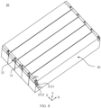
FIG. 7 is a schematic structural diagram of a battery disclosed in an embodiment of the present application; -
FIG. 8 is a schematic structural diagram of a battery disclosed in an embodiment of the present application; -
FIG. 9 is a schematic flowchart of a method for producing a battery cell according to an embodiment of the present application; and -
FIG. 10 is a schematic block diagram of an apparatus for producing a battery cell according to an embodiment of the present application. - Embodiments of the present application will be further described below in detail with reference to the accompanying drawings and embodiments. The detailed description of the following embodiments and the accompanying drawings are used to exemplarily illustrate principles of the present application, but cannot be used to limit the scope of the present application, that is, the present application is not limited to the described embodiments.
- In the description of the present application, it should be noted that unless otherwise stated, the meaning of "a plurality of' means two or more, orientations or positional relationships indicated by terms such as "up", "down", "left", "right", "inside" and "outside" are merely for convenience of describing the present application and for simplifying the description, but not for indicating or implying that an indicated apparatus or element must have a specific orientation and/or must be constructed and operated in a specific orientation, which thus shall not be understood as limitation to the present application. In addition, the terms such as "first", "second", and "third" are merely intended for the purpose of description, and shall not be understood as an indication or implication of relative importance. "Vertical" is not strictly vertical, but within the allowable range of error. "Parallel" is not strictly parallel, but within an allowable range of error.
- The terms representing directions in the following description are all directions shown in the drawings, which is not for limiting the specific structure of the present application. In the description of the present application, it should be noted that unless otherwise explicitly specified and limited, the terms "installation", "interconnection" and "connection" should be understood in a broad sense, for example, they may either be a fixed connection, a detachable connection, or an integrated connection; and they may either be a direct connection or an indirect connection through an intermediate medium. Those of ordinary skill in the art may understand the specific meanings of the foregoing terms in the present application according to a specific situation.
- In the present application, the term "and/or" is only an association relation describing associated objects, which means that there may be three relations, for example, A and/or B may represent three situations: A exists alone, both A and B exist, and B exists alone. In addition, the character "/" in the present application generally indicates that the associated objects before and after the character are in an "or" relation.
- Unless otherwise defined, all technical and scientific terms used in the present application have the same meanings as those commonly understood by those skilled in the art to which the present application belongs. The terms used in the specification of the present application are merely for the purpose of describing specific embodiments, but are not intended to limit the present application. The terms "comprising" and "having" and any variations thereof in the specification and the claims of the present application as well as the foregoing description of the accompanying drawings are intended to cover non-exclusive inclusions. The terms "first", "second" and the like in the specification and the claims of the present application as well as the above drawings are used to distinguish different objects, rather than to describe a specific order or primary-secondary relationship.
- The phrase "embodiment" referred to in the present application means that the descriptions of specific features, structures, and characteristics in combination with the embodiments are included in at least one embodiment of the present application. The phrase at various locations in the specification does not necessarily refer to the same embodiment, or an independent or alternative embodiment exclusive of another embodiment. Those skilled in the art understand, in explicit and implicit manners, that an embodiment described in the present application may be combined with another embodiment.
- Although the present application has been described with reference to the preferred embodiments, various improvements may be made to the present application and the components therein may be replaced with equivalents without departing from the scope of the present application. In particular, as long as there is no structural conflict, various technical features mentioned in the various embodiments may be combined in any manner. The present application is not limited to the specific embodiments disclosed herein, and includes all technical solutions falling within the scope of the claims.
- In the present application, a battery refers to a physical module including one or more battery cells to provide electric energy. For example, the battery mentioned in the present application may include a battery module or a battery pack. The battery generally includes a box for enclosing one or more battery cells. The box can prevent liquid or other foreign matters from affecting the charging or discharging of the battery cell.
- Optionally, a battery cell may include a lithium-ion secondary battery, a lithium-ion primary battery, a lithium-sulfur battery, a sodium/lithium-ion battery, a sodium-ion battery or a magnesium-ion battery, etc., which is not limited by the embodiments of the present application. In some embodiments, a battery cell may also be referred to as a cell.
- The battery cell includes an electrode assembly and an electrolyte, and the electrode assembly is composed of a positive electrode sheet, a negative electrode sheet and a separator. The operation of the battery cell mainly relies on movement of metal ions between the positive electrode sheet and the negative electrode sheet. The positive electrode sheet includes a positive electrode current collector and a positive active material layer. The positive active material layer is coated on a surface of the positive electrode current collector, and the current collector not coated with the positive active material layer protrudes from the current collector coated with the positive active material layer and is used as a positive electrode tab. A lithium-ion battery is taken as an example, the material of the positive electrode current collector may be aluminum, and the positive electrode active material may be lithium cobalt oxides, lithium iron phosphate, ternary lithium or lithium manganate, or the like. The negative electrode sheet includes a negative electrode current collector and a negative active material layer. The negative active material layer is coated on a surface of the negative electrode current collector, and the current collector not coated with the negative active material layer protrudes from the current collector coated with the negative active material layer and is used as a negative electrode tab. The material of the negative electrode current collector may be copper, and the negative electrode active material may be carbon or silicon, and like. In order to ensure that a large current is passed without fusing, positive electrode tabs are multiple in number and stacked together, and negative electrode tabs are multiple in number and stacked together. A material of the separator may be polypropylene (PP), polyethylene (PE), or the like. In addition, the electrode assembly may be a winding structure or a laminated structure, and the embodiments of the present application are not limited thereto.
- In order to meet different power requirements, the plurality of battery cells may be in series connection, parallel connection, or series-parallel connection, where the series-parallel connection refers to a combination of series connection and parallel connection. Optionally, the plurality of battery cells may be first connected in series, in parallel or in series and parallel to form battery modules, and then a plurality of battery modules are connected in series, in parallel or in series and parallel to form a battery. That is, a plurality of battery cells may directly form a battery, or may first form battery modules, and then the battery modules form a battery. The battery is further disposed in the power consumption device to provide electric energy for the power consumption device.
- With the development of the battery technology, it is necessary to consider many design factors, such as energy density, cycle life, discharge capacity, C-rate, and other performance parameters. In addition, the technology of battery assembly should also be considered. The battery assembly process is relatively complicated, and requires a lot of time and manpower. Therefore, it is necessary to simplify the battery assembly process and improve the battery assembly efficiency.
- A battery generally includes a plurality of battery cells, and electrical connection between the battery cells is usually achieved through a bus component inside the battery, for example, parallel connection, or series connection, or series-parallel connection. Specifically, the electrical connection between the battery cells may be achieved by the bus component connecting to electrode terminals of the battery cells. However, the battery cells connected through the bus component tend to form a suspended structure, and the bus component is also easily damaged due to external forces, for example, it is broken due to impact. Therefore, a beam or a spacer plate is usually added between the battery modules formed by the plurality of battery cells to reinforce the strength between the battery cells. However, this method will inevitably increase the battery assembly process, increase the difficulty of battery assembly, and reduce the battery assembly efficiency.
- In view of this, the present application provides a battery cell, a first pin of a first connector of a battery cell is connected to an electrode tab of an electrode assembly, and electrical connection between the battery cells can be achieved after an external connector is plugged with the first connector. That is, for the battery cell in the present application, the electrical connection between the battery cells can be achieved by plugging the first connector with the external connector. The conventional way to achieve the electrical connection between the battery cells is generally to provide an electrode terminal on the battery cell, and the electrode terminal needs to be welded to the bus component or be connected to the bus component through an adapting plate, and thus the electrical connection between the battery cells is achieved. This process increases the difficulty and consumes time for battery assembly. However, for the battery cell in the present application, the electrical connection between the battery cells can be achieved by plugging the first connector with the external connector. Thus, there is no need to provide an electrode terminal on the battery cell, and there is no need to provide a bus component to be connected to the electrode terminal, which improves the assembly efficiency, saves the space occupied by the bus component, and improves a utilization rate of the internal space of the battery. In addition, a housing of the battery cell has a stepped structure at an end portion in a first direction, and the first connector is disposed on the stepped structure. The stepped structure provides a space of the first connector, such that the first connector does not need to occupy an additional space inside the battery, thereby ensuring a reasonable utilization of the internal space of the battery and improving a utilization rate of the internal space of the battery.
- The technical solutions described in the embodiments of the present application are applicable to various power consumption devices using batteries. The power consumption device may be a vehicle, a cell phone, a portable device, a notebook computer, a ship, a spacecraft, an electric toy, an electric tool, or the like. The vehicle may be a fuel vehicle, a gas vehicle or a new energy vehicle; the new energy vehicle may be a pure electric vehicle, a hybrid vehicle or an extended range vehicle, etc.; the spacecraft include an airplane, a rocket, a space shuttle and a spaceship, etc.; the electric toy includes a fixed or mobile electric toy, such as a game console, an electric vehicle toy, an electric ship toy and an electric airplane toy, etc.; the electric tool includes a metal cutting power tool, a grinding power tool, an assembly power tool and a railway power tool, such as an electric drill, an electric grinder, an electric wrench, an electric screwdriver, an electric hammer, an impact drill, a concrete vibrator, and an electric planer, etc. The embodiment of the present application does not impose special restrictions on the above power consumption devices.
- For the convenience of description, the following embodiments take a vehicle as an example of the power consumption device for description.
- For example, as shown in
FIG. 1, FIG. 1 is a schematic structural diagram of avehicle 1 according to an embodiment of the present application. Thevehicle 1 may be a fuel-powered vehicle, a gas-powered vehicle or a new-energy vehicle. The new-energy vehicle may be a battery electric vehicle, a hybrid vehicle or an extended-range vehicle, or the like. Amotor 40, acontroller 30 and abattery 10 may be provided inside thevehicle 1, and thecontroller 30 is configured to control thebattery 10 to supply power to themotor 40. For example, thebattery 10 may be provided at the bottom or the head or the tail of thevehicle 1. Thebattery 10 may be configured to supply power to thevehicle 1. For example, thebattery 10 can be used as an operation power supply of thevehicle 1 and is used for a circuit system of thevehicle 1, for example, for a working power demand of thevehicle 1 during startup, navigation and running. In another embodiment of the present application, thebattery 10 may be used not only as an operating power source for thevehicle 1 but also as a driving power source for thevehicle 1, replacing or partially replacing fuel or natural gas to provide driving power for thevehicle 1. - The
battery 10 may include a plurality of battery cells. For example, as shown inFIG. 2, FIG. 2 is a schematic structural diagram of abattery 10 according to an embodiment of the present application, and thebattery 10 may include at least one battery module 200. The battery module 200 includes a plurality ofbattery cells 20. Thebattery 10 may further include abox 11 with the interior thereof being a hollow structure, and the plurality ofbattery cells 20 are accommodated in thebox 11. As shown inFIG. 2 , the box may include two portions, which are referred to as a first portion 111 (upper box) and a second portion 112 (lower box), respectively, and thefirst portion 111 and thesecond portion 112 are fastened together. The shapes of thefirst portion 111 and thesecond portion 112 may be determined according to the shape of the combined plurality ofbattery cells 20, and at least one of thefirst portion 111 and thesecond portion 112 has an opening. For example, as shown inFIG. 2 , thefirst portion 111 and thesecond portion 112 each may be a hollow cuboid and each have only one surface as an opening face, an opening of thefirst portion 111 is arranged opposite to an opening of thesecond portion 112, and thefirst portion 111 and thesecond portion 112 are fastened to each other to form thebox 11 with a closed chamber. For another example, different from that shown inFIG. 2 , only one of thefirst portion 111 and thesecond portion 112 may be a hollow cuboid with an opening, while the other may be a plate shape, so as to cover the opening. For example, in an example that thesecond portion 112 is a hollow cuboid and has only one face as an opening face and thefirst portion 111 is in a plate shape, an opening of thesecond portion 112 is covered by thefirst portion 111 to form thebox 11 with a closed chamber, and the chamber may be configured to accommodate the plurality ofbattery cells 20. The plurality ofbattery cells 20 are combined in parallel connection or series connection or series-parallel connection and are then placed in thebox 11 formed by fastening thefirst portion 111 to thesecond portion 112. - According to different power requirements, the number of the
battery cells 20 may be set to any value. The plurality ofbattery cells 20 may be connected in series or in parallel or in series and parallel to implement larger capacity or power. Since the number ofbattery cells 20 included in eachbattery 10 may be large, thebattery cells 20 may be provided in groups for convenience of installation, and each group ofbattery cells 20 constitutes a battery module. The number of thebattery cells 20 included in the battery module is not limited and may be set as required. The battery may include a plurality of battery modules, and these battery modules may be connected in series, in parallel or in series and parallel. - A
battery cell 20 provided by an embodiment of the present application will be described in detail below with reference toFIG. 3 andFIG. 4 . - As shown in
FIG. 3, FIG. 3 is a schematic structural diagram of abattery cell 20 provided in an embodiment of the present application. Thebattery cell 20 includes ahousing 21, an electrode assembly, and afirst connector 31. Thehousing 21 has a steppedstructure 211 at an end portion in a first direction x, the electrode assembly is dispose within thehousing 21, the electrode assembly includes an electrode tab, thefirst connector 31 is disposed at the steppedstructure 211, thefirst connector 31 includes afirst pin 311, thefirst pin 311 is connected to the electrode tab of the electrode assembly, and thefirst connector 31 is configured to be capable of being plugged with anexternal connector 32 to achieve electrical connection between thebattery cells 20. - The stepped
structure 211 of thehousing 21 may be obtained by various processing techniques, such as stamping, machining, etc. Thehousing 21 and the steppedstructure 211 may also be integrally formed, which is not limited in the present application. - The electrode assembly is a component in the
battery cell 20 where electrochemical reaction occurs. The electrode assembly may be a cylinder, a cuboid, etc. If the electrode assembly is a cylinder structure, thehousing 21 may also be a cylinder structure. If the electrode assembly is a cuboid structure, thehousing 21 may also be a cuboid structure. - The
first connector 31 refers to an electronic device that has function of transmitting signals and conducting current, for example, it may be a BTB/FPC connector, a Type-C connector, a USB connector, etc., which is not limited in the present application. - Since a
first pin 311 of afirst connector 31 of abattery cell 20 is connected to an electrode tab of an electrode assembly, and electrical connection between thebattery cells 20 can be achieved after anexternal connector 32 is plugged with thefirst connector 31. That is, for thebattery cell 20 in the present application, the electrical connection between thebattery cells 20 can be achieved by plugging thefirst connector 31 with theexternal connector 32. The conventional way to achieve the electrical connection between thebattery cells 20 is generally to provide an electrode terminal on thebattery cell 20, and the electrode terminal needs to be welded to the bus component or be connected to the bus component through an adapting plate, and thus the electrical connection between thebattery cells 20 is achieved. This process increases the difficulty and consumes time for assembly of thebattery 10. However, for thebattery cell 20 in the present application, the electrical connection between thebattery cells 20 can be achieved by plugging thefirst connector 31 with theexternal connector 32. Thus, there is no need to provide an electrode terminal on thebattery cell 20, and there is no need to provide a bus component to be connected to the electrode terminal, which improves the assembly efficiency, saves the space occupied by the bus component, and improves a utilization rate of the internal space of thebattery 10. In addition, ahousing 21 of thebattery cell 20 has a steppedstructure 211 at an end portion in a first direction x, and thefirst connector 31 is disposed on the steppedstructure 211. The steppedstructure 211 provides a space of thefirst connector 31, such that thefirst connector 31 does not need to occupy an additional space inside thebattery 10, thereby ensuring a reasonable utilization of the internal space of thebattery 10 and improving a utilization rate of the internal space of thebattery 10. - In an embodiment of the present application, the stepped
structure 211 includes a first steppedsurface 2111 perpendicular to the first direction x and a second steppedsurface 2112 perpendicular to a second direction y, and the second direction y is perpendicular to the first direction x. As shown inFIG. 3 , thefirst connector 31 is disposed on the second steppedsurface 2112, and thefirst pin 311 is parallel to the first steppedsurface 2111 and extends in a third direction z. Alternatively, as shown inFIG. 4 , thefirst connector 31 is disposed on the first steppedsurface 2111, and thefirst pin 311 is parallel to the second steppedsurface 2112 and extends in a third direction z; and the third direction z is perpendicular to the first direction x and the second direction y. - The stepped
structure 211 is provided with a first steppedsurface 2111 perpendicular to the first direction x and a second steppedsurface 2112 perpendicular to the second direction y, and in this way, an "L"-shaped structure composed of the first steppedsurface 2111 and the second steppedsurface 2112 forms a square space on thehousing 21 of thebattery cell 20 such that when thefirst connector 31 is disposed at the steppedstructure 211, it can be placed in the square space without occupying other areas in thebattery 10. Thefirst connector 31 may be disposed on the first steppedsurface 2111, and may also be disposed on the second steppedsurface 2112. When thefirst connector 31 is disposed on the first steppedsurface 2111, itsfirst pin 311 is parallel to the second steppedsurface 2112, and theexternal connector 32 is plugged with thefirst connector 31 in the first direction x. When thefirst connector 31 is disposed on the second steppedsurface 2112, itsfirst pin 311 is parallel to the first steppedsurface 2111, and theexternal connector 32 is plugged with thefirst connector 31 in the second direction y. - In an embodiment of the present application, as shown in
FIG. 3 , when thefirst connector 31 is disposed on the second steppedsurface 2112, in the second direction y, a length H1 of thefirst connector 31 protruding from the second steppedsurface 2112 is not greater than a length H2 of the first steppedsurface 2111 protruding from the second steppedsurface 2112. Alternatively, as shown inFIG. 4 , when thefirst connector 31 is disposed on the first steppedsurface 2111, in the first direction x, a length W1 of thefirst connector 31 protruding from the first steppedsurface 2111 is not greater than a length W2 of the second steppedsurface 2112 protruding from the first steppedsurface 2111. - When the
first connector 31 is disposed on the second steppedsurface 2112, in the second direction y, a length H1 of thefirst connector 31 protruding from the second steppedsurface 2112 is set to be not greater than a length H2 of the first steppedsurface 2111 protruding from the second steppedsurface 2112, so as to ensure that in the second direction y, a space occupied by thefirst connector 31 is completely the space where the first steppedsurface 2111 is located, and thus the space of other areas inside thebattery 10 will not be occupied. Similarly, when thefirst connector 31 is disposed on the first steppedsurface 2111, in the first direction x, a length W1 of thefirst connector 31 protruding from the first steppedsurface 2111 is set to be not greater than a length W2 of the second steppedsurface 2112 protruding from the first steppedsurface 2111, so as to ensure that in the first direction x, a space occupied by thefirst connector 31 is completely the space where the second steppedsurface 2112 is located, and thus the space of other areas inside thebattery 10 will not be occupied. - In an embodiment of the present application, a length L1 of the
first connector 31 in the third direction z is not greater than a length L2 of thehousing 21 in the third direction z. - A length L1 of the
first connector 31 in the third direction z is set to be not greater than a length L2 of thehousing 21 in the third direction z, so as to ensure that in the third direction z, a space occupied by thefirst connector 31 is completely the space occupied by the steppedstructure 211, and thus the space of other areas inside thebattery 10 will not be occupied. - In an embodiment of the present application, as shown in
FIG. 5 , thefirst connector 31 further includes a first pluggingframe 312, and as shown inFIG. 6 , theexternal connector 32 includes a second pluggingframe 322 and asecond pin 321, and the first pluggingframe 312 is configured to be plugged with the second pluggingframe 322 such that thefirst pin 311 and thesecond pin 321 are connected. - Optionally, when the
first pin 311 is located at the center of the first pluggingframe 312, in order to facilitate that the first pluggingframe 312 is smoothly plugged with the second pluggingframe 322, thesecond pin 321 is disposed on an inner surface of the second pluggingframe 322. The sizes of thefirst pin 311 and thesecond pin 321 are controlled to ensure that thefirst pin 311 and thesecond pin 321 can be fully connected when the first pluggingframe 312 is plugged with the second pluggingframe 322. - Optionally, when the
second pin 321 is located at the center of the second pluggingframe 322, in order to facilitate that the first pluggingframe 312 is smoothly plugged with the second pluggingframe 322, thefirst pin 311 is disposed on an inner surface of the first pluggingframe 312. The sizes of thefirst pin 311 and thesecond pin 321 are controlled to ensure that thefirst pin 311 and thesecond pin 321 can be well connected when the first pluggingframe 312 is plugged with the second pluggingframe 322. - When the first plugging
frame 312 of thefirst connector 31 is plugged with the second pluggingframe 322 of theexternal connector 32, thefirst pin 311 is connected to thesecond pin 321, to achieve electrical connection between thefirst connector 31 and theexternal connector 32. - In an embodiment of the present application, the electrode assembly includes a first electrode tab and a second electrode tab, the
housing 21 is provided withfirst connectors 31 at both ends in the first direction x, thefirst connectors 31 are respectively connected to the first electrode tab and the second electrode tab, and polarities of the first electrode tab and the second electrode tab are opposite. - The
housing 21 is provided withfirst connectors 31 at both ends in the first direction x, such that the twofirst connectors 31 at both ends are respectively connected to the first electrode tab and the second electrode tab, to achieve electrical connection between thebattery cell 20 and thefirst connector 31. - In an embodiment of the present application, the
first connector 31 further includes athird pin 313 configured to sample thebattery cell 20. - By setting a
third pin 313 configured to sample thebattery cell 20, information about thebattery cell 20 is obtained. - In an embodiment of the present application, the
first connector 31 further includes a third pluggingframe 314, theexternal connector 32 further includes a fourth pluggingframe 324 and afourth pin 323, and the third pluggingframe 314 is configured to be plugged with the fourth pluggingframe 324 such that thethird pin 313 and thefourth pin 323 are connected. - Optionally, when the
third pin 313 is located at the center of the first pluggingframe 312, in order to facilitate that the first pluggingframe 312 is smoothly plugged with the second pluggingframe 322, thefourth pin 323 is disposed on an inner surface of the second pluggingframe 322. The sizes of thethird pin 313 and thefourth pin 323 are controlled to ensure that thethird pin 313 and thefourth pin 323 can be fully connected when the first pluggingframe 312 is plugged with the second pluggingframe 322. - Optionally, when the
fourth pin 323 is located at the center of the second pluggingframe 322, in order to facilitate that the first pluggingframe 312 is smoothly plugged with the second pluggingframe 322, thethird pin 313 is disposed on an inner surface of the first pluggingframe 312. The sizes of thethird pin 313 and thefourth pin 323 are controlled to ensure that thethird pin 313 and thefourth pin 323 can be fully connected when the first pluggingframe 312 is plugged with the second pluggingframe 322. - When the third plugging
frame 314 of thefirst connector 31 is plugged with the fourth pluggingframe 324 of theexternal connector 32, thethird pin 313 is connected to thefourth pin 323, to achieve electrical connection between thefirst connector 31 and theexternal connector 32. - In an embodiment of the present application, the first plugging
frame 312 and the third pluggingframe 314 are arranged in the third direction z, and the second pluggingframe 322 and the fourth pluggingframe 324 are arranged in the third direction z. - The first plugging
frame 312 and the third pluggingframe 314 are arranged in a third direction z, to make full use of the space of the steppedstructure 211. The first pluggingframe 312 is plugged with the second pluggingframe 322 and the third pluggingframe 314 is plugged with the fourth pluggingframe 324, and accordingly, the second pluggingframe 322 and the fourth pluggingframe 324 are arranged in a third direction z, to facilitate plugging. - As shown in
FIG. 7 andFIG. 8 , an embodiment of the present application also provides abattery 10, including: a plurality ofbattery cells 20 as described in any of the foregoing embodiments, where the plurality ofbattery cells 20 are arranged in the three direction z; and a plurality ofexternal connectors 32 configured to be plugged withfirst connectors 31 of the plurality ofbattery cells 20 respectively to electrically connect the plurality ofbattery cells 20. - In an embodiment of the present application, the plurality of the
external connectors 32 are integrally provided as a connection row. - The plurality of
external connectors 32 are integrally provided as a connection row, which can be plugged with thefirst connectors 31 of the plurality ofbattery cells 20 at the same time, so that the operation is convenient, the battery assembly is facilitated, and the assembly efficiency is improved. - In an embodiment of the present application, after the connection row is plugged with the
first connector 31, as shown inFIG. 7 , in the second direction y, a first distance H3 of the connection row from the second steppedsurface 2112 is not greater than a length H4 of the first steppedsurface 2111 protruding from the second steppedsurface 2112, where the first distance H3 is a distance from the second steppedsurface 2112 at a position on the connection row farthest from the second steppedsurface 2112 in the second direction y. Alternatively, as shown inFIG. 8 , in the first direction x, a second distance W3 of the connection row from the first steppedsurface 2111 is not greater than a length W4 of the second steppedsurface 2112 protruding from the first steppedsurface 2111, where the second distance W3 is a distance from the first steppedsurface 2111 at a position on the connection row farthest from the first steppedsurface 2111 in the first direction x. - After the connection row is plugged with the
first connector 31, in the second direction y, a first distance H3 from the second steppedsurface 2112 at a position on the connection row farthest from the second steppedsurface 2112 is set to be not greater than a length H4 of the first steppedsurface 2111 protruding from the second steppedsurface 2112, so as to ensure that after the connection row is plugged with thefirst connector 31, a space occupied in the second direction y is completely the space occupied by the first steppedsurface 2111 without occupying the space of other areas inside thebattery 10. Similarly, in the first direction x, a second distance W3 from the first steppedsurface 2111 at a position on the connection row farthest from the first steppedsurface 2111 is set to be not greater than a length W4 of the second steppedsurface 2112 protruding from the first steppedsurface 2111, so as to ensure that after the connection row is plugged with thefirst connector 31, a space occupied in the first direction x is completely the space occupied by the second steppedsurface 2112, without occupying the space of other areas inside thebattery 10. - According to an embodiment of the present application, a power consumption device is also provided, including the battery in the foregoing embodiment, where the battery being configured to provide electric energy. Optionally, the power consumption device may be a
vehicle 1, a ship or a spacecraft, etc., but this is not limited by the embodiment of the present application. - The
battery cell 20, thebattery 10, and the power consumption device of the embodiments of the present application are described above, and a method and apparatus for producing abattery cell 20 of an embodiments of the present application will be described below. For the parts that are not described in detail, reference is made to the foregoing embodiments. -
FIG. 9 shows a schematic flowchart of amethod 400 for producing abattery cell 20 according to an embodiment of the present application. As shown inFIG. 9 , themethod 400 may include at least part of the following content: - S410, providing a
housing 21, thehousing 21 having a steppedstructure 211 at an end portion in a first direction x; - S420, providing an electrode assembly, the electrode assembly being disposed within the
housing 21, the electrode assembly including an electrode tab; and - S430, providing a
first connector 31, thefirst connector 31 being disposed at the steppedstructure 211, thefirst connector 31 including afirst pin 311, and thefirst pin 311 being connected to the electrode tab of the electrode assembly, and thefirst connector 31 being configured to be capable of being plugged with anexternal connector 32 to achieve electrical connection between thebattery cells 20. -
FIG. 10 shows a schematic block diagram of anapparatus 500 for producing abattery cell 20 according to an embodiment of the present application. As shown inFIG. 10 , theapparatus 500 includes: - a first providing
module 510, configured to provide ahousing 21, thehousing 21 having a steppedstructure 211 at an end portion in a first direction x; - a second providing
module 510, configured to provide an electrode assembly, the electrode assembly being disposed within thehousing 21, the electrode assembly including an electrode tab; and - a third providing
module 520, configured to provide afirst connector 31, thefirst connector 31 being disposed at the steppedstructure 211, thefirst connector 31 including afirst pin 311, and thefirst pin 311 being connected to the electrode tab of the electrode assembly, and thefirst connector 31 being configured to be capable of being plugged with anexternal connector 32 to achieve electrical connection between thebattery cells 20. - Although the present application has been described with reference to the preferred embodiments, various improvements may be made to the present application and the components therein may be replaced with equivalents without departing from the scope of the present application. In particular, as long as there is no structural conflict, various technical features mentioned in the various embodiments may be combined in any manner. The present application is not limited to the specific embodiments disclosed herein, and includes all technical solutions falling within the scope of the claims.
Claims (15)
- A battery cell (20), comprising:a housing (21), the housing (21) having a stepped structure (211) at an end portion in a first direction x;an electrode assembly, disposed within the housing (21), the electrode assembly comprising an electrode tab; anda first connector (31), disposed at the stepped structure (211), the first connector (31) comprising a first pin (311), and the first pin (311) being connected to the electrode tab of the electrode assembly, and the first connector (31) being configured to be capable of being plugged with an external connector (32) to achieve electrical connection.
- The battery cell (20) according to claim 1, wherein the stepped structure (211) comprises a first stepped surface (2111) perpendicular to the first direction x and a second stepped surface (2112) perpendicular to a second direction y, the second direction y is perpendicular to the first direction x; the first connector (31) is disposed on the second stepped surface (2112), and the first pin (311) is parallel to the first stepped surface (2111) and extends in a third direction z; or the first connector (31) is disposed on the first stepped surface (2111), and the first pin (311) is parallel to the second stepped surface (2112) and extends in the third direction z; and the third direction z is perpendicular to the first direction x and the second direction y.
- The battery cell (20) according to claim 2, wherein when the first connector (31) is disposed on the second stepped surface (2112), in the second direction y, a length of the first connector (31) protruding from the second stepped surface (2112) is not greater than a length of the first stepped surface (2111) protruding from the second stepped surface (2112); or when the first connector (31) is disposed on the first stepped surface (2111), in the first direction x, a length of the first connector (31) protruding from the first stepped surface (2111) is not greater than a length of the second stepped surface (2112) protruding from the first stepped surface (2111).
- The battery cell (20) according to claim 2 or 3, wherein a length of the first connector (31) in the third direction z is not greater than a length of the housing (21) in the third direction z.
- The battery cell (20) according to any one of claims 2 to 4, wherein the first connector (31) further comprises a first plugging frame (312), and the external connector (32) comprises a second plugging frame (322) and a second pin (321), and the first plugging frame (312) is configured to be plugged with the second plugging frame (322) such that the first pin (311) and the second pin (321) are connected.
- The battery cell (20) according to any one of claims 2 to 5, wherein the electrode assembly comprises a first electrode tab and a second electrode tab, the housing (21) is provided with first connectors (31) at both ends in the first direction x, the first connectors (31) are respectively connected to the first electrode tab and the second electrode tab, and polarities of the first electrode tab and the second electrode tab are opposite.
- The battery cell (20) according to any one of claims 2 to 6, wherein the first connector (31) further comprises a third pin (313) configured to sample the battery cell (20).
- The battery cell (20) according to claim 7, wherein the first connector (31) further comprises a third plugging frame (314), the external connector (32) further comprises a fourth plugging frame (324) and a fourth pin (323), and the third plugging frame (314) is configured to be plugged with the fourth plugging frame (324) such that the third pin (313) and the fourth pin (323) are connected.
- The battery cell (20) according to claim 8, wherein the first plugging frame (312) and the third plugging frame (314) are arranged in the third direction z, and the second plugging frame (322) and the fourth plugging frame (324) are arranged in the third direction z.
- A battery (10), comprising:a plurality of battery cells (20) according to any one of claims 1 to 9; anda plurality of external connectors (32) configured to be plugged with first connectors (31) of the plurality of battery cells (20) respectively to electrically connect the plurality of battery cells (20).
- The battery (10) according to claim 10, wherein the plurality of the external connectors (32) are integrally provided as a connection row.
- The battery (10) according to claim 11, wherein the stepped structure (211) comprises a first stepped surface (2111) perpendicular to the first direction x and a second stepped surface (2112) perpendicular to a second direction y, the second direction y is perpendicular to the first direction x; and after the connection row is plugged with the first connector (31), in the second direction y, a first distance of the connection row from the second stepped surface (2112) is not greater than a length of the first stepped surface (2111) protruding from the second stepped surface (2112), wherein the first distance is a distance from the second stepped surface (2112) at a position on the connection row farthest from the second stepped surface (2112) in the second direction y; or in the first direction x, a second distance of the connection row from the first stepped surface (2111) is not greater than a length of the second stepped surface (2112) protruding from the first stepped surface (2111), wherein the second distance is a distance from the first stepped surface (2111) at a position on the connection row farthest from the first stepped surface (2111) in the first direction x.
- A power consumption device, comprising:
the battery (10) according to any one of claims 10 to 12, the battery (10) being configured to provide electric energy for the power consumption device. - A method for producing a battery cell (20), comprising:providing a housing (21), the housing (21) having a stepped structure (211) at an end portion in a first direction x;providing an electrode assembly, the electrode assembly being disposed within the housing (21), the electrode assembly comprising an electrode tab; andproviding a first connector (31), the first connector (31) being disposed at the stepped structure (211), the first connector (31) comprising a first pin (311), and the first pin (311) being connected to the electrode tab of the electrode assembly, and the first connector (31) being configured to be capable of being plugged with an external connector (32) to achieve electrical connection.
- An apparatus for producing a battery cell (20), comprising:a first providing module, configured to provide a housing (21), the housing (21) having a stepped structure (211) at an end portion in a first direction x;a second providing module, configured to provide an electrode assembly, the electrode assembly being disposed within the housing (21), the electrode assembly comprising an electrode tab; anda third providing module, configured to provide a first connector (31), the first connector (31) being disposed at the stepped structure (211), the first connector (31) comprising a first pin (311), and the first pin (311) being connected to the electrode tab of the electrode assembly, and the first connector (31) being configured to be capable of being plugged with an external connector (32) to achieve electrical connection.
Applications Claiming Priority (1)
| Application Number | Priority Date | Filing Date | Title |
|---|---|---|---|
| PCT/CN2022/085082 WO2023184540A1 (en) | 2022-04-02 | 2022-04-02 | Battery cell, battery and electric device |
Publications (2)
| Publication Number | Publication Date |
|---|---|
| EP4280368A1 true EP4280368A1 (en) | 2023-11-22 |
| EP4280368A4 EP4280368A4 (en) | 2024-04-10 |
Family
ID=88198859
Family Applications (1)
| Application Number | Title | Priority Date | Filing Date |
|---|---|---|---|
| EP22919278.6A Pending EP4280368A4 (en) | 2022-04-02 | 2022-04-02 | BATTERY CELL, BATTERY AND ELECTRICAL DEVICE |
Country Status (4)
| Country | Link |
|---|---|
| US (1) | US20240162581A1 (en) |
| EP (1) | EP4280368A4 (en) |
| CN (1) | CN117178425A (en) |
| WO (1) | WO2023184540A1 (en) |
Family Cites Families (11)
| Publication number | Priority date | Publication date | Assignee | Title |
|---|---|---|---|---|
| US5496657A (en) * | 1994-03-16 | 1996-03-05 | Dixon, Jr.; Alfred R. | Modular battery system comprising individual interconnected modules |
| JP4644419B2 (en) * | 2003-07-31 | 2011-03-02 | 古河電池株式会社 | Manufacturing method of storage battery having socket type terminal and storage battery |
| DE102012223561A1 (en) * | 2012-12-18 | 2014-06-18 | Robert Bosch Gmbh | Battery cell with receptacle-like cell terminal and corresponding cell connector |
| JP6221778B2 (en) * | 2014-01-28 | 2017-11-01 | 株式会社豊田自動織機 | Power storage device |
| CN205211802U (en) * | 2015-12-01 | 2016-05-04 | 宁德时代新能源科技股份有限公司 | Secondary cell top cap and secondary cell |
| CN106816571B (en) * | 2015-12-01 | 2022-11-15 | 宁德时代新能源科技股份有限公司 | electrical connection device |
| JP6697685B2 (en) * | 2017-02-06 | 2020-05-27 | トヨタ自動車株式会社 | Sealed batteries and assembled batteries |
| DE102017214303A1 (en) * | 2017-08-16 | 2019-02-21 | Volkswagen Aktiengesellschaft | Arrangement for the electrical contacting of cell modules of a battery, battery with such an arrangement and vehicle |
| DE102018114764B4 (en) * | 2018-06-20 | 2020-02-20 | Lisa Dräxlmaier GmbH | PLUG-IN MODULE CONNECTOR, CONNECTING SYSTEM AND METHOD FOR ELECTRICALLY CONDUCTING CONNECTING AT LEAST TWO BATTERY MODULES |
| CN112310514A (en) * | 2020-10-27 | 2021-02-02 | 合肥国轩高科动力能源有限公司 | Lithium ion battery |
| CN114039173B (en) * | 2021-10-25 | 2023-07-14 | 东莞新能安科技有限公司 | Electrochemical devices, battery modules and electrical equipment |
-
2022
- 2022-04-02 EP EP22919278.6A patent/EP4280368A4/en active Pending
- 2022-04-02 WO PCT/CN2022/085082 patent/WO2023184540A1/en not_active Ceased
- 2022-04-02 CN CN202280005914.XA patent/CN117178425A/en active Pending
-
2023
- 2023-07-20 US US18/355,730 patent/US20240162581A1/en active Pending
Also Published As
| Publication number | Publication date |
|---|---|
| WO2023184540A1 (en) | 2023-10-05 |
| EP4280368A4 (en) | 2024-04-10 |
| US20240162581A1 (en) | 2024-05-16 |
| CN117178425A (en) | 2023-12-05 |
Similar Documents
| Publication | Publication Date | Title |
|---|---|---|
| CN116762202B (en) | Battery cell, manufacturing method and manufacturing system thereof, battery and electricity utilization device | |
| EP4044329A1 (en) | Battery box body, battery, electric device, and method and device for manufacturing box body | |
| CN219017869U (en) | Battery cell, battery and electricity utilization device | |
| US20240283099A1 (en) | Battery cell, battery, power consumption device, and method and device for producing battery cell | |
| US12542334B2 (en) | Electrode assembly, battery cell, battery and electrical device | |
| US20230268601A1 (en) | Battery, power consumption device, and method and device for producing battery | |
| KR102820869B1 (en) | Battery cells, batteries and electrical appliances | |
| US20240283109A1 (en) | Battery cell, method and system for manufacturing battery cell, battery and electrical apparatus | |
| US20220247043A1 (en) | Battery cell, battery, power consumption device and battery cell manufaturing method and device | |
| US20240047802A1 (en) | Battery, manufacturing method and manufacturing system thereof and electric device | |
| US20250079651A1 (en) | Battery Cell, Battery and Electrical Equipment | |
| US20240396128A1 (en) | Battery cell, battery, and electric device | |
| WO2025213669A1 (en) | Battery cell, battery pack, electrical device, and energy storage device | |
| US20260018690A1 (en) | High-voltage box, battery, and electrical device | |
| CN219144431U (en) | Electrode assembly, battery cell, battery and electricity utilization device | |
| CN218887454U (en) | Battery cell, battery and power consumption device | |
| WO2024020916A1 (en) | Sampling apparatus, battery, and electrical device | |
| US20240250346A1 (en) | Battery cell, method and system for manufacturing battery cell, battery and electrical device | |
| EP4280368A1 (en) | Battery cell, battery and electric device | |
| EP4583277A1 (en) | Battery and electric device | |
| CN217182341U (en) | Connecting piece, battery monomer containing same, battery and power consumption device | |
| CN221466747U (en) | Battery module, battery and power utilization device | |
| CN224123413U (en) | Battery cell, battery device and electricity utilization device | |
| US20250087789A1 (en) | Battery cell, battery, and electric apparatus | |
| CN224110331U (en) | Battery cells, battery packs and electrical devices |
Legal Events
| Date | Code | Title | Description |
|---|---|---|---|
| STAA | Information on the status of an ep patent application or granted ep patent |
Free format text: STATUS: UNKNOWN |
|
| STAA | Information on the status of an ep patent application or granted ep patent |
Free format text: STATUS: THE INTERNATIONAL PUBLICATION HAS BEEN MADE |
|
| PUAI | Public reference made under article 153(3) epc to a published international application that has entered the european phase |
Free format text: ORIGINAL CODE: 0009012 |
|
| STAA | Information on the status of an ep patent application or granted ep patent |
Free format text: STATUS: REQUEST FOR EXAMINATION WAS MADE |
|
| 17P | Request for examination filed |
Effective date: 20230718 |
|
| AK | Designated contracting states |
Kind code of ref document: A1 Designated state(s): AL AT BE BG CH CY CZ DE DK EE ES FI FR GB GR HR HU IE IS IT LI LT LU LV MC MK MT NL NO PL PT RO RS SE SI SK SM TR |
|
| A4 | Supplementary search report drawn up and despatched |
Effective date: 20240307 |
|
| RIC1 | Information provided on ipc code assigned before grant |
Ipc: H01M 50/298 20210101ALI20240301BHEP Ipc: H01M 50/296 20210101ALI20240301BHEP Ipc: H01M 50/103 20210101ALI20240301BHEP Ipc: H01M 10/04 20060101ALI20240301BHEP Ipc: H01M 50/543 20210101AFI20240301BHEP |
|
| RAP1 | Party data changed (applicant data changed or rights of an application transferred) |
Owner name: CONTEMPORARY AMPEREX TECHNOLOGY(HONG KONG) LIMITED |
|
| STAA | Information on the status of an ep patent application or granted ep patent |
Free format text: STATUS: EXAMINATION IS IN PROGRESS |
|
| 17Q | First examination report despatched |
Effective date: 20241220 |
|
| DAV | Request for validation of the european patent (deleted) | ||
| DAX | Request for extension of the european patent (deleted) |