EP4280356A1 - Battery pack and output end protection support - Google Patents
Battery pack and output end protection support Download PDFInfo
- Publication number
- EP4280356A1 EP4280356A1 EP22202365.7A EP22202365A EP4280356A1 EP 4280356 A1 EP4280356 A1 EP 4280356A1 EP 22202365 A EP22202365 A EP 22202365A EP 4280356 A1 EP4280356 A1 EP 4280356A1
- Authority
- EP
- European Patent Office
- Prior art keywords
- output end
- end protection
- protection support
- battery pack
- output
- Prior art date
- Legal status (The legal status is an assumption and is not a legal conclusion. Google has not performed a legal analysis and makes no representation as to the accuracy of the status listed.)
- Pending
Links
- 238000005192 partition Methods 0.000 claims description 34
- 230000006978 adaptation Effects 0.000 description 2
- 238000003780 insertion Methods 0.000 description 2
- 230000037431 insertion Effects 0.000 description 2
- RYGMFSIKBFXOCR-UHFFFAOYSA-N Copper Chemical compound [Cu] RYGMFSIKBFXOCR-UHFFFAOYSA-N 0.000 description 1
- 230000000712 assembly Effects 0.000 description 1
- 238000000429 assembly Methods 0.000 description 1
- 229910052802 copper Inorganic materials 0.000 description 1
- 239000010949 copper Substances 0.000 description 1
- 230000007423 decrease Effects 0.000 description 1
- 238000009413 insulation Methods 0.000 description 1
- 238000000034 method Methods 0.000 description 1
- 238000012986 modification Methods 0.000 description 1
- 230000004048 modification Effects 0.000 description 1
- 230000003014 reinforcing effect Effects 0.000 description 1
Images


Classifications
-
- H—ELECTRICITY
- H01—ELECTRIC ELEMENTS
- H01M—PROCESSES OR MEANS, e.g. BATTERIES, FOR THE DIRECT CONVERSION OF CHEMICAL ENERGY INTO ELECTRICAL ENERGY
- H01M50/00—Constructional details or processes of manufacture of the non-active parts of electrochemical cells other than fuel cells, e.g. hybrid cells
- H01M50/20—Mountings; Secondary casings or frames; Racks, modules or packs; Suspension devices; Shock absorbers; Transport or carrying devices; Holders
- H01M50/204—Racks, modules or packs for multiple batteries or multiple cells
-
- H—ELECTRICITY
- H01—ELECTRIC ELEMENTS
- H01M—PROCESSES OR MEANS, e.g. BATTERIES, FOR THE DIRECT CONVERSION OF CHEMICAL ENERGY INTO ELECTRICAL ENERGY
- H01M50/00—Constructional details or processes of manufacture of the non-active parts of electrochemical cells other than fuel cells, e.g. hybrid cells
- H01M50/20—Mountings; Secondary casings or frames; Racks, modules or packs; Suspension devices; Shock absorbers; Transport or carrying devices; Holders
- H01M50/202—Casings or frames around the primary casing of a single cell or a single battery
-
- H—ELECTRICITY
- H01—ELECTRIC ELEMENTS
- H01M—PROCESSES OR MEANS, e.g. BATTERIES, FOR THE DIRECT CONVERSION OF CHEMICAL ENERGY INTO ELECTRICAL ENERGY
- H01M50/00—Constructional details or processes of manufacture of the non-active parts of electrochemical cells other than fuel cells, e.g. hybrid cells
- H01M50/20—Mountings; Secondary casings or frames; Racks, modules or packs; Suspension devices; Shock absorbers; Transport or carrying devices; Holders
- H01M50/204—Racks, modules or packs for multiple batteries or multiple cells
- H01M50/207—Racks, modules or packs for multiple batteries or multiple cells characterised by their shape
- H01M50/209—Racks, modules or packs for multiple batteries or multiple cells characterised by their shape adapted for prismatic or rectangular cells
-
- H—ELECTRICITY
- H01—ELECTRIC ELEMENTS
- H01M—PROCESSES OR MEANS, e.g. BATTERIES, FOR THE DIRECT CONVERSION OF CHEMICAL ENERGY INTO ELECTRICAL ENERGY
- H01M50/00—Constructional details or processes of manufacture of the non-active parts of electrochemical cells other than fuel cells, e.g. hybrid cells
- H01M50/20—Mountings; Secondary casings or frames; Racks, modules or packs; Suspension devices; Shock absorbers; Transport or carrying devices; Holders
- H01M50/244—Secondary casings; Racks; Suspension devices; Carrying devices; Holders characterised by their mounting method
-
- H—ELECTRICITY
- H01—ELECTRIC ELEMENTS
- H01M—PROCESSES OR MEANS, e.g. BATTERIES, FOR THE DIRECT CONVERSION OF CHEMICAL ENERGY INTO ELECTRICAL ENERGY
- H01M50/00—Constructional details or processes of manufacture of the non-active parts of electrochemical cells other than fuel cells, e.g. hybrid cells
- H01M50/20—Mountings; Secondary casings or frames; Racks, modules or packs; Suspension devices; Shock absorbers; Transport or carrying devices; Holders
- H01M50/289—Mountings; Secondary casings or frames; Racks, modules or packs; Suspension devices; Shock absorbers; Transport or carrying devices; Holders characterised by spacing elements or positioning means within frames, racks or packs
- H01M50/291—Mountings; Secondary casings or frames; Racks, modules or packs; Suspension devices; Shock absorbers; Transport or carrying devices; Holders characterised by spacing elements or positioning means within frames, racks or packs characterised by their shape
-
- H—ELECTRICITY
- H01—ELECTRIC ELEMENTS
- H01M—PROCESSES OR MEANS, e.g. BATTERIES, FOR THE DIRECT CONVERSION OF CHEMICAL ENERGY INTO ELECTRICAL ENERGY
- H01M50/00—Constructional details or processes of manufacture of the non-active parts of electrochemical cells other than fuel cells, e.g. hybrid cells
- H01M50/20—Mountings; Secondary casings or frames; Racks, modules or packs; Suspension devices; Shock absorbers; Transport or carrying devices; Holders
- H01M50/296—Mountings; Secondary casings or frames; Racks, modules or packs; Suspension devices; Shock absorbers; Transport or carrying devices; Holders characterised by terminals of battery packs
-
- H—ELECTRICITY
- H01—ELECTRIC ELEMENTS
- H01M—PROCESSES OR MEANS, e.g. BATTERIES, FOR THE DIRECT CONVERSION OF CHEMICAL ENERGY INTO ELECTRICAL ENERGY
- H01M50/00—Constructional details or processes of manufacture of the non-active parts of electrochemical cells other than fuel cells, e.g. hybrid cells
- H01M50/50—Current conducting connections for cells or batteries
- H01M50/502—Interconnectors for connecting terminals of adjacent batteries; Interconnectors for connecting cells outside a battery casing
- H01M50/514—Methods for interconnecting adjacent batteries or cells
- H01M50/517—Methods for interconnecting adjacent batteries or cells by fixing means, e.g. screws, rivets or bolts
-
- H—ELECTRICITY
- H01—ELECTRIC ELEMENTS
- H01M—PROCESSES OR MEANS, e.g. BATTERIES, FOR THE DIRECT CONVERSION OF CHEMICAL ENERGY INTO ELECTRICAL ENERGY
- H01M50/00—Constructional details or processes of manufacture of the non-active parts of electrochemical cells other than fuel cells, e.g. hybrid cells
- H01M50/50—Current conducting connections for cells or batteries
- H01M50/528—Fixed electrical connections, i.e. not intended for disconnection
-
- H—ELECTRICITY
- H01—ELECTRIC ELEMENTS
- H01M—PROCESSES OR MEANS, e.g. BATTERIES, FOR THE DIRECT CONVERSION OF CHEMICAL ENERGY INTO ELECTRICAL ENERGY
- H01M50/00—Constructional details or processes of manufacture of the non-active parts of electrochemical cells other than fuel cells, e.g. hybrid cells
- H01M50/50—Current conducting connections for cells or batteries
- H01M50/543—Terminals
- H01M50/564—Terminals characterised by their manufacturing process
- H01M50/567—Terminals characterised by their manufacturing process by fixing means, e.g. screws, rivets or bolts
-
- H—ELECTRICITY
- H01—ELECTRIC ELEMENTS
- H01M—PROCESSES OR MEANS, e.g. BATTERIES, FOR THE DIRECT CONVERSION OF CHEMICAL ENERGY INTO ELECTRICAL ENERGY
- H01M50/00—Constructional details or processes of manufacture of the non-active parts of electrochemical cells other than fuel cells, e.g. hybrid cells
- H01M50/50—Current conducting connections for cells or batteries
- H01M50/572—Means for preventing undesired use or discharge
- H01M50/584—Means for preventing undesired use or discharge for preventing incorrect connections inside or outside the batteries
- H01M50/59—Means for preventing undesired use or discharge for preventing incorrect connections inside or outside the batteries characterised by the protection means
-
- Y—GENERAL TAGGING OF NEW TECHNOLOGICAL DEVELOPMENTS; GENERAL TAGGING OF CROSS-SECTIONAL TECHNOLOGIES SPANNING OVER SEVERAL SECTIONS OF THE IPC; TECHNICAL SUBJECTS COVERED BY FORMER USPC CROSS-REFERENCE ART COLLECTIONS [XRACs] AND DIGESTS
- Y02—TECHNOLOGIES OR APPLICATIONS FOR MITIGATION OR ADAPTATION AGAINST CLIMATE CHANGE
- Y02E—REDUCTION OF GREENHOUSE GAS [GHG] EMISSIONS, RELATED TO ENERGY GENERATION, TRANSMISSION OR DISTRIBUTION
- Y02E60/00—Enabling technologies; Technologies with a potential or indirect contribution to GHG emissions mitigation
- Y02E60/10—Energy storage using batteries
Definitions
- the disclosure relates to the technical field of batteries, in particular to a battery pack and an output end protection support.
- the position between the output pole of the battery assembly in the battery pack and the protection support cannot be accurately positioned, resulting in a dimensional deviation in the connection between the output pole and the protection support, and therefore the output pole and the protection support cannot be closely fitted.
- the contact resistance is larger, which causes a lot of heat to be generated, and results in safety risks of the battery pack.
- the present disclosure provides a battery pack and an output end protection support.
- a battery pack in a first aspect of the present disclosure, includes A box body, a first output end protection support, and a second output end protection support.
- the first output end protection support is arranged on the box body.
- the second output end protection support is arranged on the box body, the first output end protection support is directly connected to the second output end protection support, and the first output end protection support and the second output end protection support are movably arranged relative to each other.
- an output end protection support in a second aspect of the present disclosure, there is provided an output end protection support.
- the output end protection support includes a main body.
- the main body includes a first surface and a second surface opposite to each other, the first surface and the second surface are respectively provided with a slot and a slide block.
- the slot and the slide block correspond in shape such that the slot is configured to be able to receive a slide block of another output end protection support, or the slide block of the output end protection support is configured to be able to insert a slot of another output end protection support.
- connection In particular, a reference to “the” object or “a” and “an” object is intended to denote also one of a possible plurality of such objects.
- the terms “connect”, “fix” should be broadly interpreted, for example, the term “connect” can be “fixedly connect”, “detachably connect”, “integrally connect”, “electrically connect” or “signal connect”.
- the term “connect” also can be “directly connect” or “indirectly connect via a medium”.
- the present embodiment provides a battery pack, which includes a box body 10, a first output end protection support 20, and a second output end protection support 30.
- the first output end protection support 20 and the second output end protection support 30 are both disposed on the box body 10.
- the first output end protection support 20 is directly connected to the second output end protection support 30, and the first output end protection support 20 and the second output end protection support 30 are movably disposed relative to each other.
- the first output end protection support 20 and the second output end protection support 30 are arranged in the box body 10, and the first output end protection support 20 and the second output end protection support 30 are directly connected.
- the first output end protection support 20 and the second output end protection support 30 are movably arranged relative to each other in the connection direction of the first output end protection support 20 and the second output end protection support 30, by moving the first output end protection support 20 or the second output end protection support 30, it is possible to ensure that the output pole of the battery assembly may be accurately connected to the first output end protection support 20 or the second output end protection support 30.
- first output end protection support 20 and the second output end protection support 30 are arranged in the box body 10 means that the first output end protection support 20 and the second output end protection support 30 may be arranged inside the box body 10, and may also be arranged on the box body 10.
- the box body 10 includes a bottom plate 11 and a main frame, and the main frame is disposed on the bottom plate 11 to form a battery accommodating space.
- the first output end protection support 20 and the second output end protection support 30 are both disposed on the main frame, and the first output end protection support 20 and the second output end protection support 30 are both movably arranged along the main frame.
- first output end protection support 20 and the second output end protection support 30 may move relative to each other in a direction parallel to the bottom plate 11.
- the first output end protection support 20 and the second output end protection support 30 are movably arranged relative to each other in a set direction on a plane parallel to the bottom plate 11, and the set direction is perpendicular to the arrangement direction of the first output end protection support 20 and the second output end protection support 30.
- the first output end protection support 20 and the second output end protection support 30 are arranged in the arrow direction X, and the set direction is parallel to the arrow direction Y in FIG. 3 .
- the first output end protection support 20 and the second output end protection support 30 are movably disposed relative to each other in the arrow direction Y on a plane parallel to the bottom plate 11. Specifically, the first output end protection support 20 may move in the arrow direction Y relative to the second output end protection support 30, and the second output end protection support 30 may also move in the arrow direction Y relative to the first output end protection support 20.
- first output end protection support 20 and the second output end protection support 30 may also be arranged movably relative to each other in the direction perpendicular to the bottom plate 11. In this way, it is possible to adapt to two output poles that have positions at different heights, that is, when the output poles of the two battery assemblies are not in the same plane, the position of the first output end protection support 20 or the position of the second output end protection support 30 may be adjusted in the direction perpendicular to the bottom plate 11 to be accurately docked with the two output poles.
- the battery pack further includes a first battery assembly 40 and a second battery assembly 50.
- the first battery assembly 40 includes a first output pole 41, and the first output pole 41 is connected to the first output end protection support 20.
- the second battery assembly 50 includes a second output pole 51, and the second output pole 51 is connected to the second output end protection support 30.
- the first battery assembly 40 and the second battery assembly 50 are located in the battery accommodating space, the first output pole 41 and the second output pole 51 are close to each other, and the first output end protection support 20 and the second output end protection support 30 are located between the first battery assembly 40 and the second battery assembly 50.
- the first output pole 41 is connected to the first output end protection support 20, and the second output pole 51 is connected to the second output end protection support 30.
- the position of the first output end protection support 20 and the position of the second output end protection support 30 may be adjusted respectively to ensure accurate connection between the first output pole 41 and the first output end protection support 20, and to ensure accurate connection between the second output pole 51 and the second output end protection support 30.
- the first output pole 41 and the first output end protection support 20 have been accurately connected.
- only the position of the second output pole 51 needs to be adjusted to ensure the accurate connection between the second output pole 51 and the second output end protection support 30.
- the position of the first output end protection support 20 will not be affected, which improves the assembly efficiency.
- the main frame includes a frame 122 and a partition beam 123, and the frame 122 is arranged around the bottom plate 11 to form a battery accommodating space.
- the partition beam 123 is arranged in the frame 122 to separate the battery accommodating space.
- the first battery assembly 40 and the second battery assembly 50 are respectively located on both sides of the partition beam 123, and there is a space between the partition beam 123 and the top plate (not shown in the figure) of the box body 10.
- the first output end protection support 20 and the second output end protection support 30 are both arranged on the partition beam 123, that is, the first output end protection support 20 and the second output end protection support 30 are both arranged in the space between the partition beam 123 and the top plate, the above configuration may not only improve the utilization rate of the internal space of the battery pack, but also facilitate the connection of the first output pole 41 to the first output end protection support 20 and the connection of the second output pole 51 to the second output end protection support 30.
- the first output end protection support 20 and the second output end protection support 30 are arranged in sequence in the width direction of the partition beam 123.
- the width direction of the partition beam 123 refers to the direction from one side of the partition beam 123 close to the first battery assembly 40 to one side of the partition beam 123 close to the second battery assembly 50.
- the width direction of the partition beam 123 is parallel to the arrow direction X.
- the first output end protection support 20 and the second output end protection support 30 are arranged in sequence in the width direction of the partition beam 123. Such configuration may ensure that the first output pole 41 is close to the first output end protection support 20, and the second output end protection support 30 is close to the second output pole 51 to facilitate assembly.
- first output end protection support 20 and the second output end protection support 30 are both disposed at the top end of the main frame and are movably disposed along the top end of the main frame.
- the first output end protection support 20 and the second output end protection support 30 are both disposed on the upper surface of the partition beam 123, and the first output end protection support 20 and the second output end protection support 30 are movably arranged along the upper surface of the partition beam 123.
- the upper surface of the partition beam 123 is parallel to the bottom plate 11, and the first output end protection support 20 and the second output end protection support 30 may move relative to each other in the direction parallel to the bottom plate 11 on the upper surface of the partition beam 123.
- the battery pack may further include an end plate, the end plate is configured to fix the battery assembly, and the first output end protection support 20 and the second output end protection support 30 may further be movably disposed relative to each other on the end plate.
- the battery pack further includes a conductive member 60, and the conductive member 60 is connected to the first output pole 41 and the second output pole 51.
- the conductive member 60 may be a copper bar to realize serial or parallel connection of the first battery assembly 40 and the second battery assembly 50.
- the first output end protection support 20 is provided with a first connection portion 61
- the second output end protection support 30 is provided with a second connection portion 62.
- the battery pack further includes a first fastener 91 and a second fastener 92.
- the first fastener 91 passes through the conductive member 60 and the first output pole 41, and is connected to the first connection portion 61.
- the second fastener 92 passes through the conductive member 60 and the second output pole 51, and is connected to the second connection portion 62.
- the conductive member 60 is provided with a first mounting hole and a second mounting hole.
- the first output pole 41 and the second output pole 51 are both provided with a through hole.
- the first fastener 91 passes through the first mounting hole and the through hole on the first output pole 41, and is connected to the first connection portion 61.
- the second fastener 92 passes through the second mounting hole and the through hole on the second output pole 51, and is connected to the second connection portion 62.
- first connection portion 61 is a first threaded hole
- second connection portion 62 is a second threaded hole
- the first fastener 91 is a first bolt
- the second fastener 92 is a second bolt.
- the conductive member 60 and the first output pole 41 are pressed and fixed on the first output end protection support 20.
- the conductive member 60 and the second output pole 51 are pressed and fixed on the second output end protection support 30.
- first connection portion 61 may also be a nut provided on the first output end protection support 20.
- the second connection portion 62 may also be a nut provided on the second output end protection support 30.
- the first output end protection support 20 is slidably connected to the second output end protection support 30.
- the first output end protection support 20 and the second output end protection support 30 may slide relative to each other in the length direction of the partition beam 123.
- the first output end protection support 20 is provided with a slot 4
- the second output end protection support 30 is provided with a slide block 5
- the first output end protection support 20 and the second output end protection support 30 are connected through the slot 4 and the slide block 5.
- the first output end protection support 20 and the second output end protection support 30 have the same structure.
- both the first output end protection support 20 and the second output end protection support 30 include a main body 1, and the main body 1 includes a first surface 2 and a second surface 3 opposite to each other.
- the first surface 2 of the first output end protection support 20 and the first surface 2 of the second output end protection support 30 are both provided with the slot 4.
- the second surface 3 of the first output end protection support 20 and the second surface 3 of the second output end protection support 30 are both provided with the slide block 5.
- the slot 4 of the first output end protection support 20 may be engaged with the slide block 5 of the second output end protection support 30, and the slide block 5 of the first output end protection support 20 may also be engaged with the slot 4 of the second output end protection support 30.
- the main body 1 of the first output end protection support 20 and the main body 1 of the second output end protection support 30 are substantially rectangular block structures.
- the slot 4 is a dovetail slot
- the slide block 5 is a trapezoidal slide block corresponding to the dovetail slot.
- Such configuration may improve the connection strength of two adjacent output end protection supports and prevent the two output end protection supports from being separated.
- the partition beam 123 is formed with a cavity 1231, one end of the first output end protection support 20 is inserted into the cavity 1231, and one end of the second output end protection support 30 is inserted into the cavity 1231, such that the first output end protection support 20 and the second output end protection support 30 are limited to move in the direction perpendicular to the top end of the partition beam 123.
- the partition beam 123 is a profile with a cavity 1231, an end portion of the partition beam 123 has an opening, and the opening communicates with the cavity 1231.
- One end of the first output end protection support 20 is inserted into the cavity 1231 from the opening, and one end of the second output end protection support30 is inserted into the cavity 1231 from the opening.
- the outer contour of the part of the first output end protection support 20 inserted into the cavity 1231 and the outer contour of the part of the second output end protection support 30 inserted into the cavity 1231 correspond in shape with the cavity 1231, such that the first output end protection support 20 and the second output end protection support 30 are limited to move in a direction perpendicular to the upper surface of the partition beam 123.
- one end of the main body 1 is provided with a fixing portion 8, and the fixing portion 8 may be inserted into the cavity 1231.
- the fixing portion 8 is integrally formed with the main body 1, and the fixing portion 8 has a hollow columnar structure.
- a reinforcing rib 81 is provided in the fixing portion 8.
- the fixing portion 8 may be inserted into the cavity 1231 inside the partition beam 123.
- the main body 1 has a position-limiting surface 82, and the position-limiting surface 82 may abut against the end surface of the partition beam 123 to prevent the main body 1 from being entirely pushed into the cavity 1231.
- the length direction of the fixing portion 8 is consistent with the length direction of the slot 4, that is, the insertion direction of the fixing portion 8 inserted into the cavity 1231 is consistent with the length direction of the slot 4.
- the length of the fixing portion 8 is configured to satisfy the sliding adjustment range of the main body 1 along the slot 4.
- the fixing portion 8 is never removed from the cavity 1231.
- the partition beam 123 is provided with a recessed portion 1232, and both the first output end protection support 20 and the second output end protection support 30 are located in the recessed portion 1232.
- the recessed portion 1232 is located on the upper surface of the partition beam 123, and the recessed portion 1232 is close to the end portion of the partition beam 123.
- the recessed portion 1232 has a bottom surface and a lateral surface, the bottom surface is parallel to the bottom plate 11, and the opening is provided on the lateral surface.
- Both the first output end protection support 20 and the second output end protection support 30 are located on the bottom surface of the recessed portion 1232, and the fixing portion 8 is inserted into the cavity 1231 from the opening on the lateral surface of the recessed portion 1232.
- the main body 1 is provided with engaging portions 7, the engaging portions 7 are provided in pairs, and the paired engaging portions 7 are respectively close to the first surface 2 and the second surface 3.
- the main body 1 is provided with four engaging portions 7, among which, two engaging portions 7 are arranged at intervals on one side of the main body 1 close to the first surface, and the other two engaging portions 7 are arranged at intervals on another side of the main body 1 close to the second surface.
- the two engaging portions 7 on the same side are located on both sides of the output pole of the battery pack.
- An engaging opening 71 is provided on each of the four engaging portions 7.
- the battery pack further includes a protection cover 70, the protection cover 70 is disposed at the top end of the first output end protection support 20 and the second output end protection support 30, and the protection cover 70 is engaged with the first output end protection support 20.
- the protection cover 70 is engaged with the second output end protection support 30.
- the protection cover 70 is provided with hooks 702, and the hooks 702 are respectively limited to the engaging openings 71.
- the protection cover 70 includes a top plate 701 and side walls surrounding the top plate 701.
- the hooks 702 are provided on the side walls. Specifically, two opposite side walls are respectively provided with two hooks 702. Both ends of the two opposite side walls are respectively provided with avoidance spaces, and the hooks 702 are respectively located in the avoidance spaces.
- Each of the four engaging portions 7 of the main body 1 is provided with an engaging opening 71.
- the protection cover 70 is fastened on the main body 1, and the four engaging portions 7 respectively correspond to the four avoidance spaces, and the hooks 702 are respectively limited to the engaging openings 71.
- the upper surface of the protection cover 70 is provided with a groove 703 for accommodating the low-voltage collection harness.
- the groove 703 is used to accommodate the low-voltage collection harness.
- the groove 703 is provided on the top plate 701, and the width of the bottom portion of the groove 703 is greater than the width of the groove opening to ensure interference fit between the low-voltage collection harness and the groove 703, and prevent the low-voltage collection harness from detaching from the groove 703.
- the width of the groove 703 gradually decreases in a direction from the bottom portion of the groove 703 to the groove opening.
- this embodiment further provides an output end protection support, which includes a main body 1, and the main body 1 includes a first surface 2 and a second surface 3 opposite to each other.
- the first surface 2 and the second surface 3 are respectively provided with the slot 4 and the slide block 5, and the slot 4 corresponds in shape with the slide block 5, so that the slot 4 may be used to accommodate a slide block of another output end protection support, or the slide block 5 of the output end protection support may be used to insert a slot of another output end protection support.
- the output end protection support provided in this embodiment, by disposing the slot 4 and the slide block 5 respectively on the opposite first surface 2 and the second surface 3 of the main body 1, it is easy to perform movable assembly of two output end protection supports. That is, the slot 4 of one of the output end protection supports may accommodate the slide block 5 of another output end protection support, or the slide block 5 of one of the output end protection supports may be used to insert into the slot 4 of another output end protection support. Further, by moving the output end protection support, it is possible to ensure that the output pole of the battery module may be accurately connected to the output end protection support.
- the main body 1 is provided with a connection portion 6 for connecting to a fastener.
- connection portion 6 is a threaded hole provided inside the main body 1, and may also be a nut embedded in the main body 1.
- the main body 1 is provided with engaging portions 7, the engaging portions 7 are provided in pairs, and the paired engaging portions 7 are respectively close to the first surface 2 and the second surface 3.
- the main body 1 is provided with a fixing portion 8, and the fixing portion 8 is configured to be connected to a cavity of the box body 10 of the battery pack.
- the cavity of the box body 10 may be the cavity 1231 of the partition beam 123.
- the structure of the output end protection support provided in this embodiment is the same as the structure of the first output end protection support 20, and details are not repeated here.
Landscapes
- Chemical & Material Sciences (AREA)
- Chemical Kinetics & Catalysis (AREA)
- Electrochemistry (AREA)
- General Chemical & Material Sciences (AREA)
- Battery Mounting, Suspending (AREA)
Abstract
A battery pack and an output end protection support are provided. The battery pack includes a box body (10), a first output end protection support (20), and a second output end protection support (30). The first output end protection support (20) is arranged on the box body (10). The second output end protection support (30) is arranged on the box body (10). The first output end protection support (20) is directly connected to the second output end protection support (30), and the first output end protection support (20) and the second output end protection support (30) are movably arranged relative to each other.
Description
- The disclosure relates to the technical field of batteries, in particular to a battery pack and an output end protection support.
- In the related art, the position between the output pole of the battery assembly in the battery pack and the protection support cannot be accurately positioned, resulting in a dimensional deviation in the connection between the output pole and the protection support, and therefore the output pole and the protection support cannot be closely fitted. As a result, the contact resistance is larger, which causes a lot of heat to be generated, and results in safety risks of the battery pack.
- The present disclosure provides a battery pack and an output end protection support.
- In a first aspect of the present disclosure, a battery pack is provided. The battery includes A box body, a first output end protection support, and a second output end protection support. The first output end protection support is arranged on the box body. The second output end protection support is arranged on the box body, the first output end protection support is directly connected to the second output end protection support, and the first output end protection support and the second output end protection support are movably arranged relative to each other.
- In a second aspect of the present disclosure, there is provided an output end protection support. The output end protection support includes a main body. The main body includes a first surface and a second surface opposite to each other, the first surface and the second surface are respectively provided with a slot and a slide block. The slot and the slide block correspond in shape such that the slot is configured to be able to receive a slide block of another output end protection support, or the slide block of the output end protection support is configured to be able to insert a slot of another output end protection support.
- For a better understanding of the disclosure, reference may be made to exemplary embodiments shown in the following drawings. The components in the drawings are not necessarily to scale and related elements may be omitted, or in some instances proportions may have been exaggerated, so as to emphasize and clearly illustrate the features described herein. In addition, related elements or components can be variously arranged, as known in the art. Further, in the drawings, like reference numerals designate same or like parts throughout the several views.
-
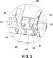
FIG. 1 is a schematic structural view of a battery pack provided by an embodiment of the present disclosure. -
FIG. 2 is a partial enlarged view of position A inFIG. 1 . -
FIG. 3 is a schematic structural view of the cooperation of the first output end protection support and the second protection support in an embodiment of the present disclosure. -
FIG. 4 is a partial schematic view of a battery pack provided by an embodiment of the present disclosure. -
FIG. 5 is a schematic structural view of a protection cover in an embodiment of the present disclosure. -
FIG. 6 is a schematic structural view of an output end protection support provided by an embodiment of the present disclosure. - The technical solutions in the exemplary embodiments of the disclosure will be described clearly and explicitly in conjunction with the drawings in the exemplary embodiments of the disclosure. The description proposed herein is just the exemplary embodiments for the purpose of illustrations only, not intended to limit the scope of the disclosure, so it should be understood that and various modifications and variations could be made thereto without departing from the scope of the disclosure.
- In the description of the present disclosure, unless otherwise specifically defined and limited, the terms "first", "second" and the like are only used for illustrative purposes and are not to be construed as expressing or implying a relative importance. The term "plurality" is two or more. The term "and/or" includes any and all combinations of one or more of the associated listed items.
- In particular, a reference to "the" object or "a" and "an" object is intended to denote also one of a possible plurality of such objects. Unless otherwise defined or described, the terms "connect", "fix" should be broadly interpreted, for example, the term "connect" can be "fixedly connect", "detachably connect", "integrally connect", "electrically connect" or "signal connect". The term "connect" also can be "directly connect" or "indirectly connect via a medium". For the persons skilled in the art, the specific meanings of the abovementioned terms in the present disclosure can be understood according to the specific situation.
- Further, in the description of the present disclosure, it should be understood that spatially relative terms, such as "above", "below" "inside", "outside" and the like, are described based on orientations illustrated in the figures, but are not intended to limit the exemplary embodiments of the present disclosure.
- In the context, it should also be understood that when an element or features is provided "outside" or "inside" of another element(s), it can be directly provided "outside" or "inside" of the other element, or be indirectly provided "outside" or "inside" of the another element(s) by an intermediate element.
- Referring to
FIG. 1 to FIG. 6 , the present embodiment provides a battery pack, which includes abox body 10, a first outputend protection support 20, and a second outputend protection support 30. The first outputend protection support 20 and the second outputend protection support 30 are both disposed on thebox body 10. The first outputend protection support 20 is directly connected to the second outputend protection support 30, and the first outputend protection support 20 and the second outputend protection support 30 are movably disposed relative to each other. - In the battery pack provided in this embodiment, the first output
end protection support 20 and the second outputend protection support 30 are arranged in thebox body 10, and the first outputend protection support 20 and the second outputend protection support 30 are directly connected. When it is necessary to connect the output pole of the battery assembly in the battery box to the first outputend protection support 20 or the second outputend protection support 30, since the first outputend protection support 20 and the second outputend protection support 30 are movably arranged relative to each other in the connection direction of the first outputend protection support 20 and the second outputend protection support 30, by moving the first outputend protection support 20 or the second outputend protection support 30, it is possible to ensure that the output pole of the battery assembly may be accurately connected to the first outputend protection support 20 or the second outputend protection support 30. - It should be understood that, the first output
end protection support 20 and the second outputend protection support 30 are arranged in thebox body 10 means that the first outputend protection support 20 and the second outputend protection support 30 may be arranged inside thebox body 10, and may also be arranged on thebox body 10. - In an embodiment, the
box body 10 includes abottom plate 11 and a main frame, and the main frame is disposed on thebottom plate 11 to form a battery accommodating space. The first outputend protection support 20 and the second outputend protection support 30 are both disposed on the main frame, and the first outputend protection support 20 and the second outputend protection support 30 are both movably arranged along the main frame. - Exemplarily, the first output end protection support 20 and the second output
end protection support 30 may move relative to each other in a direction parallel to thebottom plate 11. - The first output
end protection support 20 and the second outputend protection support 30 are movably arranged relative to each other in a set direction on a plane parallel to thebottom plate 11, and the set direction is perpendicular to the arrangement direction of the first outputend protection support 20 and the second outputend protection support 30. - Referring to
FIG. 3 , the first outputend protection support 20 and the second outputend protection support 30 are arranged in the arrow direction X, and the set direction is parallel to the arrow direction Y inFIG. 3 . The first outputend protection support 20 and the second outputend protection support 30 are movably disposed relative to each other in the arrow direction Y on a plane parallel to thebottom plate 11. Specifically, the first outputend protection support 20 may move in the arrow direction Y relative to the second outputend protection support 30, and the second outputend protection support 30 may also move in the arrow direction Y relative to the first outputend protection support 20. - It should be noted that the first output
end protection support 20 and the second outputend protection support 30 may also be arranged movably relative to each other in the direction perpendicular to thebottom plate 11. In this way, it is possible to adapt to two output poles that have positions at different heights, that is, when the output poles of the two battery assemblies are not in the same plane, the position of the first outputend protection support 20 or the position of the second outputend protection support 30 may be adjusted in the direction perpendicular to thebottom plate 11 to be accurately docked with the two output poles. - In an embodiment, as shown in
FIG. 1 , the battery pack further includes afirst battery assembly 40 and asecond battery assembly 50. Thefirst battery assembly 40 includes afirst output pole 41, and thefirst output pole 41 is connected to the first outputend protection support 20. Thesecond battery assembly 50 includes asecond output pole 51, and thesecond output pole 51 is connected to the second outputend protection support 30. - The
first battery assembly 40 and thesecond battery assembly 50 are located in the battery accommodating space, thefirst output pole 41 and thesecond output pole 51 are close to each other, and the first outputend protection support 20 and the second outputend protection support 30 are located between thefirst battery assembly 40 and thesecond battery assembly 50. Thefirst output pole 41 is connected to the first outputend protection support 20, and thesecond output pole 51 is connected to the second outputend protection support 30. - Exemplarily, the position of the first output
end protection support 20 and the position of the second outputend protection support 30 may be adjusted respectively to ensure accurate connection between thefirst output pole 41 and the first outputend protection support 20, and to ensure accurate connection between thesecond output pole 51 and the second outputend protection support 30. - For example, during the assembly process, the
first output pole 41 and the first outputend protection support 20 have been accurately connected. Under the circumstances, only the position of thesecond output pole 51 needs to be adjusted to ensure the accurate connection between thesecond output pole 51 and the second outputend protection support 30. The position of the first outputend protection support 20 will not be affected, which improves the assembly efficiency. - In an embodiment, as shown in
FIG. 1 , the main frame includes aframe 122 and apartition beam 123, and theframe 122 is arranged around thebottom plate 11 to form a battery accommodating space. Thepartition beam 123 is arranged in theframe 122 to separate the battery accommodating space. Thefirst battery assembly 40 and thesecond battery assembly 50 are respectively located on both sides of thepartition beam 123, and there is a space between thepartition beam 123 and the top plate (not shown in the figure) of thebox body 10. The first outputend protection support 20 and the second outputend protection support 30 are both arranged on thepartition beam 123, that is, the first outputend protection support 20 and the second outputend protection support 30 are both arranged in the space between thepartition beam 123 and the top plate, the above configuration may not only improve the utilization rate of the internal space of the battery pack, but also facilitate the connection of thefirst output pole 41 to the first outputend protection support 20 and the connection of thesecond output pole 51 to the second outputend protection support 30. - In an embodiment, the first output
end protection support 20 and the second outputend protection support 30 are arranged in sequence in the width direction of thepartition beam 123. - Specifically, the width direction of the
partition beam 123 refers to the direction from one side of thepartition beam 123 close to thefirst battery assembly 40 to one side of thepartition beam 123 close to thesecond battery assembly 50. The width direction of thepartition beam 123 is parallel to the arrow direction X. The first outputend protection support 20 and the second outputend protection support 30 are arranged in sequence in the width direction of thepartition beam 123. Such configuration may ensure that thefirst output pole 41 is close to the first outputend protection support 20, and the second outputend protection support 30 is close to thesecond output pole 51 to facilitate assembly. - In an embodiment, the first output
end protection support 20 and the second outputend protection support 30 are both disposed at the top end of the main frame and are movably disposed along the top end of the main frame. - Specifically, as shown in
FIG. 2 , the first outputend protection support 20 and the second outputend protection support 30 are both disposed on the upper surface of thepartition beam 123, and the first outputend protection support 20 and the second outputend protection support 30 are movably arranged along the upper surface of thepartition beam 123. - Exemplarily, the upper surface of the
partition beam 123 is parallel to thebottom plate 11, and the first outputend protection support 20 and the second outputend protection support 30 may move relative to each other in the direction parallel to thebottom plate 11 on the upper surface of thepartition beam 123. - It should be noted that the battery pack may further include an end plate, the end plate is configured to fix the battery assembly, and the first output
end protection support 20 and the second outputend protection support 30 may further be movably disposed relative to each other on the end plate. - In an embodiment, as shown in
FIG. 2 , the battery pack further includes aconductive member 60, and theconductive member 60 is connected to thefirst output pole 41 and thesecond output pole 51. - In some embodiments, the
conductive member 60 may be a copper bar to realize serial or parallel connection of thefirst battery assembly 40 and thesecond battery assembly 50. - In an embodiment, as shown in
FIG. 2 andFIG. 3 , the first outputend protection support 20 is provided with afirst connection portion 61, and the second outputend protection support 30 is provided with asecond connection portion 62. The battery pack further includes afirst fastener 91 and asecond fastener 92. Thefirst fastener 91 passes through theconductive member 60 and thefirst output pole 41, and is connected to thefirst connection portion 61. Thesecond fastener 92 passes through theconductive member 60 and thesecond output pole 51, and is connected to thesecond connection portion 62. - In some embodiments, the
conductive member 60 is provided with a first mounting hole and a second mounting hole. Thefirst output pole 41 and thesecond output pole 51 are both provided with a through hole. Thefirst fastener 91 passes through the first mounting hole and the through hole on thefirst output pole 41, and is connected to thefirst connection portion 61. Thesecond fastener 92 passes through the second mounting hole and the through hole on thesecond output pole 51, and is connected to thesecond connection portion 62. - In an embodiment, the
first connection portion 61 is a first threaded hole, thesecond connection portion 62 is a second threaded hole, thefirst fastener 91 is a first bolt, and thesecond fastener 92 is a second bolt. - By connecting the first bolt to the first threaded hole, the
conductive member 60 and thefirst output pole 41 are pressed and fixed on the first outputend protection support 20. By connecting the second bolt to the second threaded hole, theconductive member 60 and thesecond output pole 51 are pressed and fixed on the second outputend protection support 30. - In some embodiments, the
first connection portion 61 may also be a nut provided on the first outputend protection support 20. Thesecond connection portion 62 may also be a nut provided on the second outputend protection support 30. - In an embodiment, the first output
end protection support 20 is slidably connected to the second outputend protection support 30. Exemplarily, the first outputend protection support 20 and the second outputend protection support 30 may slide relative to each other in the length direction of thepartition beam 123. - In an embodiment, the first output
end protection support 20 is provided with a slot 4, the second outputend protection support 30 is provided with aslide block 5, and the first outputend protection support 20 and the second outputend protection support 30 are connected through the slot 4 and theslide block 5. - In an embodiment, the first output
end protection support 20 and the second outputend protection support 30 have the same structure. Specifically, both the first outputend protection support 20 and the second outputend protection support 30 include amain body 1, and themain body 1 includes a first surface 2 and asecond surface 3 opposite to each other. The first surface 2 of the first outputend protection support 20 and the first surface 2 of the second outputend protection support 30 are both provided with the slot 4. Thesecond surface 3 of the first outputend protection support 20 and thesecond surface 3 of the second outputend protection support 30 are both provided with theslide block 5. The slot 4 of the first outputend protection support 20 may be engaged with theslide block 5 of the second outputend protection support 30, and theslide block 5 of the first outputend protection support 20 may also be engaged with the slot 4 of the second outputend protection support 30. - Exemplarily, the
main body 1 of the first outputend protection support 20 and themain body 1 of the second outputend protection support 30 are substantially rectangular block structures. - Exemplarily, as shown in
FIG. 3 , the slot 4 is a dovetail slot, and theslide block 5 is a trapezoidal slide block corresponding to the dovetail slot. Such configuration may improve the connection strength of two adjacent output end protection supports and prevent the two output end protection supports from being separated. - In an embodiment, as shown in
FIG. 4 , thepartition beam 123 is formed with acavity 1231, one end of the first outputend protection support 20 is inserted into thecavity 1231, and one end of the second outputend protection support 30 is inserted into thecavity 1231, such that the first outputend protection support 20 and the second outputend protection support 30 are limited to move in the direction perpendicular to the top end of thepartition beam 123. - Specifically, the
partition beam 123 is a profile with acavity 1231, an end portion of thepartition beam 123 has an opening, and the opening communicates with thecavity 1231. One end of the first outputend protection support 20 is inserted into thecavity 1231 from the opening, and one end of the second output end protection support30 is inserted into thecavity 1231 from the opening. The outer contour of the part of the first outputend protection support 20 inserted into thecavity 1231 and the outer contour of the part of the second outputend protection support 30 inserted into thecavity 1231 correspond in shape with thecavity 1231, such that the first outputend protection support 20 and the second outputend protection support 30 are limited to move in a direction perpendicular to the upper surface of thepartition beam 123. - In an embodiment, one end of the
main body 1 is provided with a fixingportion 8, and the fixingportion 8 may be inserted into thecavity 1231. - Exemplarily, the fixing
portion 8 is integrally formed with themain body 1, and the fixingportion 8 has a hollow columnar structure. In order to improve the structural strength of the fixingportion 8, a reinforcingrib 81 is provided in the fixingportion 8. - During configuration, the fixing
portion 8 may be inserted into thecavity 1231 inside thepartition beam 123. Referring toFIG. 6 , themain body 1 has a position-limitingsurface 82, and the position-limitingsurface 82 may abut against the end surface of thepartition beam 123 to prevent themain body 1 from being entirely pushed into thecavity 1231. The length direction of the fixingportion 8 is consistent with the length direction of the slot 4, that is, the insertion direction of the fixingportion 8 inserted into thecavity 1231 is consistent with the length direction of the slot 4. The length of the fixingportion 8 is configured to satisfy the sliding adjustment range of themain body 1 along the slot 4. That is, when themain body 1 moves away from the insertion direction to adjust the alignment of the threaded hole on themain body 1 with the through hole of thefirst output pole 41 and the through hole of thesecond output pole 51, the fixingportion 8 is never removed from thecavity 1231. - In an embodiment, the
partition beam 123 is provided with a recessedportion 1232, and both the first outputend protection support 20 and the second outputend protection support 30 are located in the recessedportion 1232. - Exemplarily, referring to
FIG. 4 , the recessedportion 1232 is located on the upper surface of thepartition beam 123, and the recessedportion 1232 is close to the end portion of thepartition beam 123. The recessedportion 1232 has a bottom surface and a lateral surface, the bottom surface is parallel to thebottom plate 11, and the opening is provided on the lateral surface. Both the first outputend protection support 20 and the second outputend protection support 30 are located on the bottom surface of the recessedportion 1232, and the fixingportion 8 is inserted into thecavity 1231 from the opening on the lateral surface of the recessedportion 1232. - In an embodiment, the
main body 1 is provided with engagingportions 7, the engagingportions 7 are provided in pairs, and the paired engagingportions 7 are respectively close to the first surface 2 and thesecond surface 3. - Exemplarily, the
main body 1 is provided with fourengaging portions 7, among which, two engagingportions 7 are arranged at intervals on one side of themain body 1 close to the first surface, and the other twoengaging portions 7 are arranged at intervals on another side of themain body 1 close to the second surface. The twoengaging portions 7 on the same side are located on both sides of the output pole of the battery pack. Anengaging opening 71 is provided on each of the fourengaging portions 7. - In an embodiment, the battery pack further includes a
protection cover 70, theprotection cover 70 is disposed at the top end of the first outputend protection support 20 and the second outputend protection support 30, and theprotection cover 70 is engaged with the first outputend protection support 20. Theprotection cover 70 is engaged with the second outputend protection support 30. By disposing theprotection cover 70, at least a part of the conductive member and the output pole of the battery assembly may be covered, so as to serve the insulation and protection functions, and improve the safety of the battery pack. - In some embodiments, the
protection cover 70 is provided withhooks 702, and thehooks 702 are respectively limited to the engagingopenings 71. - Exemplarily, the
protection cover 70 includes atop plate 701 and side walls surrounding thetop plate 701. Thehooks 702 are provided on the side walls. Specifically, two opposite side walls are respectively provided with twohooks 702. Both ends of the two opposite side walls are respectively provided with avoidance spaces, and thehooks 702 are respectively located in the avoidance spaces. Each of the fourengaging portions 7 of themain body 1 is provided with an engagingopening 71. Theprotection cover 70 is fastened on themain body 1, and the fourengaging portions 7 respectively correspond to the four avoidance spaces, and thehooks 702 are respectively limited to the engagingopenings 71. - In an embodiment, the upper surface of the
protection cover 70 is provided with agroove 703 for accommodating the low-voltage collection harness. - In some embodiments, the
groove 703 is used to accommodate the low-voltage collection harness. Referring toFIG. 5 , thegroove 703 is provided on thetop plate 701, and the width of the bottom portion of thegroove 703 is greater than the width of the groove opening to ensure interference fit between the low-voltage collection harness and thegroove 703, and prevent the low-voltage collection harness from detaching from thegroove 703. Exemplarily, the width of thegroove 703 gradually decreases in a direction from the bottom portion of thegroove 703 to the groove opening. - Referring to
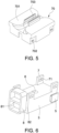
FIG. 6 , this embodiment further provides an output end protection support, which includes amain body 1, and themain body 1 includes a first surface 2 and asecond surface 3 opposite to each other. The first surface 2 and thesecond surface 3 are respectively provided with the slot 4 and theslide block 5, and the slot 4 corresponds in shape with theslide block 5, so that the slot 4 may be used to accommodate a slide block of another output end protection support, or theslide block 5 of the output end protection support may be used to insert a slot of another output end protection support. - For the output end protection support provided in this embodiment, by disposing the slot 4 and the
slide block 5 respectively on the opposite first surface 2 and thesecond surface 3 of themain body 1, it is easy to perform movable assembly of two output end protection supports. That is, the slot 4 of one of the output end protection supports may accommodate theslide block 5 of another output end protection support, or theslide block 5 of one of the output end protection supports may be used to insert into the slot 4 of another output end protection support. Further, by moving the output end protection support, it is possible to ensure that the output pole of the battery module may be accurately connected to the output end protection support. - In an embodiment, the
main body 1 is provided with aconnection portion 6 for connecting to a fastener. - In some embodiments, the
connection portion 6 is a threaded hole provided inside themain body 1, and may also be a nut embedded in themain body 1. - In an embodiment, the
main body 1 is provided with engagingportions 7, the engagingportions 7 are provided in pairs, and the paired engagingportions 7 are respectively close to the first surface 2 and thesecond surface 3. - In an embodiment, the
main body 1 is provided with a fixingportion 8, and the fixingportion 8 is configured to be connected to a cavity of thebox body 10 of the battery pack. - Exemplarily, the cavity of the
box body 10 may be thecavity 1231 of thepartition beam 123. - It should be noted that, the structure of the output end protection support provided in this embodiment is the same as the structure of the first output
end protection support 20, and details are not repeated here. - Through the connection along with slidable adjustment of the two output end protection supports provided in this embodiment, it is possible to ensure that the output pole of the battery assembly is accurately connected to the output end protection support.
- Other embodiments of the disclosure will be apparent to those skilled in the art from consideration of the specification and practice of the disclosure disclosed herein. The disclosure is intended to cover any variations, uses or adaptations of the disclosure. These variations, uses, or adaptations follow the general principles of the disclosure and include common general knowledge or conventional technical means in the art that are not disclosed in the present disclosure. The specification and embodiments are illustrative.
Claims (15)
- A battery pack, comprising:a box body (10);a first output end protection support (20), wherein the first output end protection support (20) is arranged on the box body (10); anda second output end protection support (30), wherein the second output end protection support (30) is arranged on the box body (10), the first output end protection support (20) is directly connected to the second output end protection support (30), and the first output end protection support (20) and the second output end protection support (30) are movably arranged relative to each other.
- The battery pack according to claim 1, further comprising:a first battery assembly (40), wherein the first battery assembly (40) comprises a first output pole (41), and the first output pole (41) is connected to the first output end protection support (20); anda second battery assembly (50), wherein the second battery assembly (50) comprises a second output pole (51), and the second output pole (51) is connected to the second output end protection support (30).
- The battery pack according to claim 2, further comprising:
a conductive member (60), wherein the conductive member (60) is connected to the first output pole (41) and the second output pole (51). - The battery pack according to claim 3, wherein the first output end protection support (20) is provided with a first connection portion (61), and the second output end protection support (30) is provided with a second connection portion (62), and the battery pack further comprising:a first fastener (91), wherein the first fastener (91) passes through the conductive member (60) and the first output pole (41), and is connected to the first connection portion (61); anda second fastener (92), wherein the second fastener (92) passes through the conductive member (60) and the second output pole (51), and is connected to the second connection portion (62).
- The battery pack according to claim 4, wherein the first connection portion (61) is a first threaded hole, the second connection portion (62) is a second threaded hole, the first fastener (91) is a first bolt, and the second fastener (92) is a second bolt.
- The battery pack according to claim 1, wherein the first output end protection support (20) and the second output end protection support (30) are movably arranged relative to each other in a set direction on a plane parallel to a bottom plate of the box body (10), and the set direction is perpendicular to an arrangement direction of the first output end protection support (20) and the second output end protection support (30).
- The battery pack according to any one of claims 1-6, wherein the box body (10) comprises:a bottom plate (11); anda main frame (12), wherein the main frame (12) is disposed on the bottom plate (11) to form a battery accommodating space;wherein the first output end protection support (20) and the second output end protection support (30) are both disposed on the main frame (12), and the first output end protection support (20) and the second output end protection support (30) are both movably arranged along the main frame (12).
- The battery pack according to claim 7, wherein the main frame (12) comprises:a frame (122), wherein the frame (122) is arranged around the bottom plate (11) to form the battery accommodating space; anda partition beam (123), wherein the partition beam (123) is arranged in the frame (122) to separate the battery accommodating space;wherein the first output end protection support (20) and the second output end protection support (30) are both arranged on the partition beam (123), the partition beam (123) is formed with a cavity (1231), one end of the first output end protection support (20) is inserted into the cavity (1231), and one end of the second output end protection support (30) is inserted into the cavity (1231), such that the first output end protection support (20) and the second output end protection support (30) are limited to move in a direction perpendicular to an upper surface of the partition beam (123).
- The battery pack according to claim 8, wherein the partition beam (123) is provided with a recessed portion (1232), and both the first output end protection support (20) and the second output end protection support (30) are located in the recessed portion (1232).
- The battery pack according to any one of claims 1-6, wherein the first output end protection support (20) is slidably connected to the second output end protection support (30).
- The battery pack according to claim 10, wherein the first output end protection support is provided with a slot (4), the second output end protection support (30) is provided with a slide block (5), and the first output end protection support (20) and the second output end protection support (30) are connected through the slot (4) and the slide block (5).
- The battery pack according to claim 11, wherein the first output end protection support (20) and the second output end protection support (30) have a same structure.
- An output end protection support, comprising a main body (1), wherein the main body (1) comprises a first surface (2) and a second surface (3) opposite to each other, the first surface (2) and the second surface (3) are respectively provided with a slot (4) and a slide block (5), the slot (4) and the slide block (5) correspond in shape such that the slot (4) is configured to be able to receive a slide block of another output end protection support, or the slide block (5) of the output end protection support is configured to be able to insert a slot of another output end protection support.
- The output end protection support according to claim 13, wherein the main body (1) is provided with a connection portion (6), and the connection portion (6) is adapted to be connected to a fastener.
- The output end protection support according to claim 13, wherein the main body (1) is provided with a fixing portion (8), and the fixing portion (8) is configured to be connected to a cavity (1231) of a box body (10) of a battery pack.
Applications Claiming Priority (1)
| Application Number | Priority Date | Filing Date | Title |
|---|---|---|---|
| CN202210534867.XA CN114824604A (en) | 2022-05-17 | 2022-05-17 | Battery pack and output end protection support |
Publications (1)
| Publication Number | Publication Date |
|---|---|
| EP4280356A1 true EP4280356A1 (en) | 2023-11-22 |
Family
ID=82515148
Family Applications (1)
| Application Number | Title | Priority Date | Filing Date |
|---|---|---|---|
| EP22202365.7A Pending EP4280356A1 (en) | 2022-05-17 | 2022-10-19 | Battery pack and output end protection support |
Country Status (3)
| Country | Link |
|---|---|
| US (1) | US20230378591A1 (en) |
| EP (1) | EP4280356A1 (en) |
| CN (1) | CN114824604A (en) |
Families Citing this family (1)
| Publication number | Priority date | Publication date | Assignee | Title |
|---|---|---|---|---|
| WO2024082299A1 (en) * | 2022-10-21 | 2024-04-25 | 宁德时代新能源科技股份有限公司 | Battery and electric device |
Citations (5)
| Publication number | Priority date | Publication date | Assignee | Title |
|---|---|---|---|---|
| US20180337384A1 (en) * | 2017-05-18 | 2018-11-22 | Ford Global Technologies, Llc | Battery cell securing assembly and method |
| WO2021025473A1 (en) * | 2019-08-07 | 2021-02-11 | 주식회사 엘지화학 | Upper part cooling-type battery pack |
| WO2021199070A1 (en) * | 2020-04-01 | 2021-10-07 | Tvs Motor Company Limited | A battery block |
| CN215342825U (en) * | 2021-07-29 | 2021-12-28 | 中航锂电科技有限公司 | Battery pack |
| CN215644708U (en) * | 2021-09-18 | 2022-01-25 | 中航锂电科技有限公司 | Battery |
-
2022
- 2022-05-17 CN CN202210534867.XA patent/CN114824604A/en active Pending
- 2022-10-18 US US17/967,905 patent/US20230378591A1/en active Pending
- 2022-10-19 EP EP22202365.7A patent/EP4280356A1/en active Pending
Patent Citations (5)
| Publication number | Priority date | Publication date | Assignee | Title |
|---|---|---|---|---|
| US20180337384A1 (en) * | 2017-05-18 | 2018-11-22 | Ford Global Technologies, Llc | Battery cell securing assembly and method |
| WO2021025473A1 (en) * | 2019-08-07 | 2021-02-11 | 주식회사 엘지화학 | Upper part cooling-type battery pack |
| WO2021199070A1 (en) * | 2020-04-01 | 2021-10-07 | Tvs Motor Company Limited | A battery block |
| CN215342825U (en) * | 2021-07-29 | 2021-12-28 | 中航锂电科技有限公司 | Battery pack |
| CN215644708U (en) * | 2021-09-18 | 2022-01-25 | 中航锂电科技有限公司 | Battery |
Also Published As
| Publication number | Publication date |
|---|---|
| US20230378591A1 (en) | 2023-11-23 |
| CN114824604A (en) | 2022-07-29 |
Similar Documents
| Publication | Publication Date | Title |
|---|---|---|
| CN217227308U (en) | Quick-change battery pack and electric automobile | |
| EP3565023B1 (en) | Drawer type battery pack | |
| US20240039110A1 (en) | Terminal protection device and battery module | |
| US10263236B2 (en) | Battery cell securing assembly and method | |
| EP4280356A1 (en) | Battery pack and output end protection support | |
| US20150380690A1 (en) | Battery cell case | |
| EP2835842B1 (en) | Battery module | |
| CN217306621U (en) | Battery pack and output end protection support | |
| EP4329051A1 (en) | Battery pack and assembly method of battery pack | |
| CN210744014U (en) | Battery box device and battery box system | |
| CN112670630B (en) | Battery box device and battery box system | |
| CN217306708U (en) | Output pole protector and battery package | |
| CN215817074U (en) | Multi-interlayer high-low voltage distribution box convenient to adjust | |
| CN210549706U (en) | Shell bottom separating device | |
| EP3726655B1 (en) | Terminal block and air conditioning device | |
| CN219144342U (en) | Battery energy storage system | |
| CN112928377A (en) | Integrated cover plate and power battery module | |
| CN219498007U (en) | Battery pack | |
| CN218996989U (en) | Lower cover plate of cover plate assembly | |
| CN219177397U (en) | Wireless communication equipment and bracket assembly thereof | |
| CN211295171U (en) | Frame and battery box device | |
| CN220122081U (en) | Filter | |
| US12080915B2 (en) | Electrical junction box | |
| CN222380783U (en) | Wiring harness isolation plate and battery | |
| CN220420794U (en) | Battery pack and electric equipment |
Legal Events
| Date | Code | Title | Description |
|---|---|---|---|
| PUAI | Public reference made under article 153(3) epc to a published international application that has entered the european phase |
Free format text: ORIGINAL CODE: 0009012 |
|
| STAA | Information on the status of an ep patent application or granted ep patent |
Free format text: STATUS: REQUEST FOR EXAMINATION WAS MADE |
|
| 17P | Request for examination filed |
Effective date: 20221019 |
|
| AK | Designated contracting states |
Kind code of ref document: A1 Designated state(s): AL AT BE BG CH CY CZ DE DK EE ES FI FR GB GR HR HU IE IS IT LI LT LU LV MC ME MK MT NL NO PL PT RO RS SE SI SK SM TR |