EP4280283A1 - Image sensor - Google Patents
Image sensor Download PDFInfo
- Publication number
- EP4280283A1 EP4280283A1 EP23172376.8A EP23172376A EP4280283A1 EP 4280283 A1 EP4280283 A1 EP 4280283A1 EP 23172376 A EP23172376 A EP 23172376A EP 4280283 A1 EP4280283 A1 EP 4280283A1
- Authority
- EP
- European Patent Office
- Prior art keywords
- zone
- photosensitive
- transfer
- photosite
- photosensitive zone
- Prior art date
- Legal status (The legal status is an assumption and is not a legal conclusion. Google has not performed a legal analysis and makes no representation as to the accuracy of the status listed.)
- Pending
Links
- 238000012546 transfer Methods 0.000 claims abstract description 126
- 239000000758 substrate Substances 0.000 claims abstract description 74
- 239000004065 semiconductor Substances 0.000 claims abstract description 29
- 238000009413 insulation Methods 0.000 claims description 63
- 230000005855 radiation Effects 0.000 claims description 38
- 230000002093 peripheral effect Effects 0.000 claims description 26
- 238000003860 storage Methods 0.000 claims description 10
- 238000005070 sampling Methods 0.000 claims description 6
- 101100421503 Arabidopsis thaliana SIGA gene Proteins 0.000 description 12
- 101001132841 Homo sapiens Mitochondrial ribosome-associated GTPase 1 Proteins 0.000 description 10
- 102100033815 Mitochondrial ribosome-associated GTPase 1 Human genes 0.000 description 10
- 239000011347 resin Substances 0.000 description 10
- 229920005989 resin Polymers 0.000 description 10
- 101001132833 Homo sapiens Mitochondrial ribosome-associated GTPase 2 Proteins 0.000 description 9
- 102100033820 Mitochondrial ribosome-associated GTPase 2 Human genes 0.000 description 9
- 239000003990 capacitor Substances 0.000 description 9
- 238000010586 diagram Methods 0.000 description 9
- 230000036961 partial effect Effects 0.000 description 8
- 101000761698 Hydrophis hardwickii Short neurotoxin 1 Proteins 0.000 description 7
- 230000010354 integration Effects 0.000 description 7
- 238000002955 isolation Methods 0.000 description 7
- 101100041125 Arabidopsis thaliana RST1 gene Proteins 0.000 description 6
- 101100443250 Saccharomyces cerevisiae (strain ATCC 204508 / S288c) DIG1 gene Proteins 0.000 description 6
- 239000000463 material Substances 0.000 description 6
- 230000010363 phase shift Effects 0.000 description 6
- VYPSYNLAJGMNEJ-UHFFFAOYSA-N Silicium dioxide Chemical compound O=[Si]=O VYPSYNLAJGMNEJ-UHFFFAOYSA-N 0.000 description 5
- 239000002184 metal Substances 0.000 description 5
- 229910052751 metal Inorganic materials 0.000 description 5
- 238000010521 absorption reaction Methods 0.000 description 4
- 238000001465 metallisation Methods 0.000 description 4
- 229910021420 polycrystalline silicon Inorganic materials 0.000 description 4
- RYGMFSIKBFXOCR-UHFFFAOYSA-N Copper Chemical compound [Cu] RYGMFSIKBFXOCR-UHFFFAOYSA-N 0.000 description 3
- 230000008901 benefit Effects 0.000 description 3
- 229910052802 copper Inorganic materials 0.000 description 3
- 239000010949 copper Substances 0.000 description 3
- 230000000694 effects Effects 0.000 description 3
- 230000005670 electromagnetic radiation Effects 0.000 description 3
- 230000008030 elimination Effects 0.000 description 3
- 238000003379 elimination reaction Methods 0.000 description 3
- 238000000034 method Methods 0.000 description 3
- 230000010287 polarization Effects 0.000 description 3
- 229910052814 silicon oxide Inorganic materials 0.000 description 3
- 238000002834 transmittance Methods 0.000 description 3
- 101150066718 FMOD gene Proteins 0.000 description 2
- 230000004888 barrier function Effects 0.000 description 2
- 239000003989 dielectric material Substances 0.000 description 2
- 238000005286 illumination Methods 0.000 description 2
- 230000000670 limiting effect Effects 0.000 description 2
- 229910001092 metal group alloy Inorganic materials 0.000 description 2
- 230000000051 modifying effect Effects 0.000 description 2
- 230000003287 optical effect Effects 0.000 description 2
- 238000002161 passivation Methods 0.000 description 2
- 229910052710 silicon Inorganic materials 0.000 description 2
- 239000010703 silicon Substances 0.000 description 2
- 229910004298 SiO 2 Inorganic materials 0.000 description 1
- 238000009825 accumulation Methods 0.000 description 1
- 229910045601 alloy Inorganic materials 0.000 description 1
- 239000000956 alloy Substances 0.000 description 1
- 239000004020 conductor Substances 0.000 description 1
- 229940082150 encore Drugs 0.000 description 1
- 239000012212 insulator Substances 0.000 description 1
- 238000005468 ion implantation Methods 0.000 description 1
- 238000004519 manufacturing process Methods 0.000 description 1
- 239000011159 matrix material Substances 0.000 description 1
- 238000005259 measurement Methods 0.000 description 1
- 229910044991 metal oxide Inorganic materials 0.000 description 1
- 150000004706 metal oxides Chemical class 0.000 description 1
- 230000008569 process Effects 0.000 description 1
- 238000005096 rolling process Methods 0.000 description 1
- 235000012239 silicon dioxide Nutrition 0.000 description 1
- 239000000377 silicon dioxide Substances 0.000 description 1
- 230000002123 temporal effect Effects 0.000 description 1
Images


Classifications
-
- H—ELECTRICITY
- H01—ELECTRIC ELEMENTS
- H01L—SEMICONDUCTOR DEVICES NOT COVERED BY CLASS H10
- H01L27/00—Devices consisting of a plurality of semiconductor or other solid-state components formed in or on a common substrate
- H01L27/14—Devices consisting of a plurality of semiconductor or other solid-state components formed in or on a common substrate including semiconductor components sensitive to infrared radiation, light, electromagnetic radiation of shorter wavelength or corpuscular radiation and specially adapted either for the conversion of the energy of such radiation into electrical energy or for the control of electrical energy by such radiation
- H01L27/144—Devices controlled by radiation
- H01L27/146—Imager structures
- H01L27/14643—Photodiode arrays; MOS imagers
-
- G—PHYSICS
- G01—MEASURING; TESTING
- G01S—RADIO DIRECTION-FINDING; RADIO NAVIGATION; DETERMINING DISTANCE OR VELOCITY BY USE OF RADIO WAVES; LOCATING OR PRESENCE-DETECTING BY USE OF THE REFLECTION OR RERADIATION OF RADIO WAVES; ANALOGOUS ARRANGEMENTS USING OTHER WAVES
- G01S17/00—Systems using the reflection or reradiation of electromagnetic waves other than radio waves, e.g. lidar systems
- G01S17/88—Lidar systems specially adapted for specific applications
- G01S17/89—Lidar systems specially adapted for specific applications for mapping or imaging
- G01S17/894—3D imaging with simultaneous measurement of time-of-flight at a 2D array of receiver pixels, e.g. time-of-flight cameras or flash lidar
-
- H—ELECTRICITY
- H01—ELECTRIC ELEMENTS
- H01L—SEMICONDUCTOR DEVICES NOT COVERED BY CLASS H10
- H01L27/00—Devices consisting of a plurality of semiconductor or other solid-state components formed in or on a common substrate
- H01L27/14—Devices consisting of a plurality of semiconductor or other solid-state components formed in or on a common substrate including semiconductor components sensitive to infrared radiation, light, electromagnetic radiation of shorter wavelength or corpuscular radiation and specially adapted either for the conversion of the energy of such radiation into electrical energy or for the control of electrical energy by such radiation
- H01L27/144—Devices controlled by radiation
- H01L27/146—Imager structures
- H01L27/14643—Photodiode arrays; MOS imagers
- H01L27/14645—Colour imagers
- H01L27/14647—Multicolour imagers having a stacked pixel-element structure, e.g. npn, npnpn or MQW elements
-
- G—PHYSICS
- G01—MEASURING; TESTING
- G01B—MEASURING LENGTH, THICKNESS OR SIMILAR LINEAR DIMENSIONS; MEASURING ANGLES; MEASURING AREAS; MEASURING IRREGULARITIES OF SURFACES OR CONTOURS
- G01B11/00—Measuring arrangements characterised by the use of optical techniques
- G01B11/22—Measuring arrangements characterised by the use of optical techniques for measuring depth
-
- G—PHYSICS
- G01—MEASURING; TESTING
- G01S—RADIO DIRECTION-FINDING; RADIO NAVIGATION; DETERMINING DISTANCE OR VELOCITY BY USE OF RADIO WAVES; LOCATING OR PRESENCE-DETECTING BY USE OF THE REFLECTION OR RERADIATION OF RADIO WAVES; ANALOGOUS ARRANGEMENTS USING OTHER WAVES
- G01S7/00—Details of systems according to groups G01S13/00, G01S15/00, G01S17/00
- G01S7/48—Details of systems according to groups G01S13/00, G01S15/00, G01S17/00 of systems according to group G01S17/00
- G01S7/481—Constructional features, e.g. arrangements of optical elements
- G01S7/4816—Constructional features, e.g. arrangements of optical elements of receivers alone
-
- H—ELECTRICITY
- H01—ELECTRIC ELEMENTS
- H01L—SEMICONDUCTOR DEVICES NOT COVERED BY CLASS H10
- H01L27/00—Devices consisting of a plurality of semiconductor or other solid-state components formed in or on a common substrate
- H01L27/14—Devices consisting of a plurality of semiconductor or other solid-state components formed in or on a common substrate including semiconductor components sensitive to infrared radiation, light, electromagnetic radiation of shorter wavelength or corpuscular radiation and specially adapted either for the conversion of the energy of such radiation into electrical energy or for the control of electrical energy by such radiation
- H01L27/144—Devices controlled by radiation
- H01L27/146—Imager structures
- H01L27/14601—Structural or functional details thereof
- H01L27/14603—Special geometry or disposition of pixel-elements, address-lines or gate-electrodes
-
- H—ELECTRICITY
- H01—ELECTRIC ELEMENTS
- H01L—SEMICONDUCTOR DEVICES NOT COVERED BY CLASS H10
- H01L27/00—Devices consisting of a plurality of semiconductor or other solid-state components formed in or on a common substrate
- H01L27/14—Devices consisting of a plurality of semiconductor or other solid-state components formed in or on a common substrate including semiconductor components sensitive to infrared radiation, light, electromagnetic radiation of shorter wavelength or corpuscular radiation and specially adapted either for the conversion of the energy of such radiation into electrical energy or for the control of electrical energy by such radiation
- H01L27/144—Devices controlled by radiation
- H01L27/146—Imager structures
- H01L27/14601—Structural or functional details thereof
- H01L27/14609—Pixel-elements with integrated switching, control, storage or amplification elements
- H01L27/1461—Pixel-elements with integrated switching, control, storage or amplification elements characterised by the photosensitive area
-
- H—ELECTRICITY
- H01—ELECTRIC ELEMENTS
- H01L—SEMICONDUCTOR DEVICES NOT COVERED BY CLASS H10
- H01L27/00—Devices consisting of a plurality of semiconductor or other solid-state components formed in or on a common substrate
- H01L27/14—Devices consisting of a plurality of semiconductor or other solid-state components formed in or on a common substrate including semiconductor components sensitive to infrared radiation, light, electromagnetic radiation of shorter wavelength or corpuscular radiation and specially adapted either for the conversion of the energy of such radiation into electrical energy or for the control of electrical energy by such radiation
- H01L27/144—Devices controlled by radiation
- H01L27/146—Imager structures
- H01L27/14601—Structural or functional details thereof
- H01L27/14609—Pixel-elements with integrated switching, control, storage or amplification elements
- H01L27/14612—Pixel-elements with integrated switching, control, storage or amplification elements involving a transistor
-
- H—ELECTRICITY
- H01—ELECTRIC ELEMENTS
- H01L—SEMICONDUCTOR DEVICES NOT COVERED BY CLASS H10
- H01L27/00—Devices consisting of a plurality of semiconductor or other solid-state components formed in or on a common substrate
- H01L27/14—Devices consisting of a plurality of semiconductor or other solid-state components formed in or on a common substrate including semiconductor components sensitive to infrared radiation, light, electromagnetic radiation of shorter wavelength or corpuscular radiation and specially adapted either for the conversion of the energy of such radiation into electrical energy or for the control of electrical energy by such radiation
- H01L27/144—Devices controlled by radiation
- H01L27/146—Imager structures
- H01L27/14601—Structural or functional details thereof
- H01L27/14638—Structures specially adapted for transferring the charges across the imager perpendicular to the imaging plane
-
- H—ELECTRICITY
- H01—ELECTRIC ELEMENTS
- H01L—SEMICONDUCTOR DEVICES NOT COVERED BY CLASS H10
- H01L27/00—Devices consisting of a plurality of semiconductor or other solid-state components formed in or on a common substrate
- H01L27/14—Devices consisting of a plurality of semiconductor or other solid-state components formed in or on a common substrate including semiconductor components sensitive to infrared radiation, light, electromagnetic radiation of shorter wavelength or corpuscular radiation and specially adapted either for the conversion of the energy of such radiation into electrical energy or for the control of electrical energy by such radiation
- H01L27/144—Devices controlled by radiation
- H01L27/146—Imager structures
- H01L27/14601—Structural or functional details thereof
- H01L27/1463—Pixel isolation structures
Definitions
- the present description generally concerns the field of image acquisition devices.
- the present description relates more particularly to image acquisition devices adapted to acquire a 2D image and a depth image of a scene by means of the same pixel array.
- Image acquisition devices capable of acquiring a 2D image and a depth image of a scene are known.
- devices are known comprising 2D image pixels and depth pixels forming part of the same pixel array of an image sensor.
- An object of one embodiment is to overcome all or part of the drawbacks of known devices for acquiring a 2D image and a depth image of a scene.
- One embodiment more precisely aims to facilitate the integration of depth pixels into a pixel array of an image sensor adapted to acquire 2D images and depth images.
- the first charge collection zone is common to the charges photogenerated in the first, second and third photosensitive zones.
- the first transfer grid surrounds the fourth transfer grid.
- each photosite further comprises a peripheral insulation trench extending vertically in the semiconductor substrate, from said face, and laterally delimiting the first photosensitive zone.
- the senor further comprises a fifth transfer grid extending horizontally on said face directly above the second photosensitive zone, the fifth transfer grid being adapted to transfer photogenerated charges from the second photosensitive zone towards a second charge collection zone.
- the second and fifth transfer gates are successively opened during a sampling phase of photogenerated charges in the second photosensitive zone.
- the second and fifth transfer gates are interconnected by a switch.
- the first and second photosensitive zones of the photosites of the sensor are intended to respectively capture a 2D image and a depth image of a scene.
- the first and second photosensitive zones are doped with the same type of conductivity.
- the first photosensitive zone is doped with a first type of conductivity and the second photosensitive zone is doped with a second type of conductivity, opposite to the first type of conductivity.
- transmittance of a layer designates a ratio between the intensity of the radiation leaving the layer and the intensity of the radiation entering the layer.
- a layer or film is said to be opaque to radiation when the transmittance of the radiation through the layer or film is less than 10%.
- a layer or film is said to be transparent to radiation when the transmittance of the radiation through the layer or film is greater than 10%.
- visible light designates electromagnetic radiation whose wavelength is between 380 and 780 nm
- infrared radiation designates electromagnetic radiation whose wavelength is between 780 nm and 15 ⁇ m.
- near infrared radiation refers more precisely to electromagnetic radiation whose wavelength is between 750 nm and 1.1 ⁇ m.
- a pixel of an image corresponds to the unit element of the image captured by an image sensor.
- the image sensor is a color image sensor, it generally includes, for each pixel of the color image to be acquired, a group of at least three photosites. Each of these three photosites acquires light radiation substantially in a single color (for example red, green or blue), for example in a wavelength range of less than 100 nm.
- the image sensor is a depth image sensor, it can comprise, for each pixel of the depth image to be acquired, one or more photosites each allowing part of the depth information to be acquired.
- the expressions “approximately”, “approximately”, “substantially”, and “of the order of” mean to the nearest 10%, preferably to the nearest 5%.
- FIG. 1 is a schematic and partial top view of an image sensor photosite 100 according to one embodiment.
- THE Figures 2A and 2B are sectional views, according to plans AA and BB of the figure 1 , respectively, of the photosite 100 of the figure 1 .
- the photosite 100 is formed in and on a semiconductor substrate 101, for example made of silicon.
- the substrate 101 has a thickness of between 3 and 20 ⁇ m.
- the photosite 100 comprises a first photosensitive zone 103 formed in the semiconductor substrate 101.
- there first photosensitive zone 103 extends vertically in the thickness of the semiconductor substrate 101 from a lower face 101B of the substrate 101 to a depth less than the thickness of the substrate 101.
- the first photosensitive zone 103 of the photosite 100 has, seen from above, a circumference of approximately square shape.
- the first photosensitive zone 103 is for example formed in a first region 105 of the semiconductor substrate 101 doped with a first type of conductivity, for example type N, and having a doping level N1.
- the first photosensitive zone 103 can for example constitute a first photosensitive diode D1, or photodiode, for example a pinched photodiode having a pinching voltage Vpin1.
- the photosite 100 further comprises a second photosensitive zone 107 formed in the semiconductor substrate 101.
- the second photosensitive zone 107 is located directly above the first photosensitive zone 103 (above the first photosensitive zone 103, in the orientation of Figures 2A and 2B ).
- the second photosensitive zone 107 extends vertically in the thickness of the semiconductor substrate 101, from an upper face 101T of the substrate 101 opposite the lower face 101B, to a depth less than the thickness of the substrate 101.
- the second photosensitive zone 107 has for example a rectangular shape.
- the second photosensitive zone 107 has for example lateral dimensions smaller than those of the first photosensitive zone 103.
- the rectangle formed by the second photosensitive zone 107 is inscribed inside the square formed by the first photosensitive zone 103.
- the second photosensitive zone 107 is for example formed in a second region 109 of the substrate 101 doped with the first type of conductivity, type N in this example, and having a doping level N2.
- the doping level N2 of the second region 109 of the substrate 101 is for example greater than the doping level N1 of the first region 105.
- the second region 109 of the substrate 101 is in contact, via its lower face, with the upper face of the first underlying region 105.
- the second photosensitive zone 107 is substantially in contact, via its lower face, with the upper face of the underlying first photosensitive zone 103.
- the second photosensitive zone 107 can for example constitute a second photosensitive diode D2, for example a pinched photodiode having a pinching voltage Vpin2.
- the pinch voltage Vpin2 of the second photodiode D2 is greater than the pinch voltage Vpin1 of the first photodiode D1.
- Each photosensitive zone 103, 107 is for example intended to collect incident photons, during illumination phases of the image sensor of which photosite 100 is a part, and to convert these photons into electron-hole pairs.
- the first photosensitive zone 103 is adapted to capture light in a first range of wavelengths and the second photosensitive zone 107 is adapted to capture light in a second range of wavelengths, different from the first wavelength range.
- the first and second photosensitive zones 103 and 107 are for example intended to capture respectively 2D images and depth images of a scene.
- the first photosensitive zone 103 of the photosite 100 is adapted to capture visible light, for example blue light
- the second photosensitive zone 107 of the photosite 100 is adapted to capture infrared radiation, for example near infrared radiation, when the photosite 100 is illuminated from the side of its lower face 101B.
- the visible light and the infrared radiation are mainly absorbed at different depths in the semiconductor substrate 101 from its lower face 101B.
- the majority absorption depth of visible light is lower than that of infrared radiation.
- the second photosensitive zone 107 may for example have a thickness greater than that of the first photosensitive zone 103 in order to optimize the absorption of infrared radiation in the second photosensitive zone 107.
- the photosite 100 further comprises a peripheral insulation trench 111, for example a capacitive insulation trench, laterally delimiting the first photosensitive zone 103. More precisely, in this example, the peripheral insulation trench 111 borders all the side faces of the first photosensitive zone 103 and has, in top view, a substantially square-shaped perimeter.
- a peripheral insulation trench 111 for example a capacitive insulation trench
- the peripheral isolation trench 111 makes it possible to electrically isolate the first and second photosensitive zones 103 and 107 of the photosite 100 with respect to the photosensitive zones of neighboring photosites, not shown in figures 1, 2A and 2B .
- the peripheral insulation trench 111 is formed in the substrate 101. In the orientation of the Figures 2A and 2B , the peripheral insulation trench 111 extends vertically in the thickness of the substrate 101, from the upper face 101T of the substrate 101, to the lower face 101B of the substrate 101. In other words, the trench of peripheral insulation 111 extends vertically, in this example, over the entire thickness of the substrate 101 and opens onto the side of the upper 101T and lower 101B faces of the substrate 101.
- the peripheral isolation trench 111 has for example a width of between 30 and 600 nm, and a depth of between 5 and 20 ⁇ m. In the example illustrated in Figures 2A and 2B , the peripheral insulation trench 111 has a depth equal to the thickness of the substrate 101.
- the peripheral insulation trench 111 comprises for example an electrically conductive region whose side walls are coated with an electrically insulating layer. This layer electrically insulates the electrically conductive region of the trench 111 with respect to the substrate 101.
- the electrically conductive region of the trench 111 is made of polycrystalline silicon or of a metal, for example copper, or of an alloy metallic, and the electrically insulating layer of the trench 111 is made of a dielectric material, for example silicon oxide.
- the peripheral isolation trench 111 is a CDTI (Capacitive Deep Trench Isolation) type trench, or deep capacitive insulation trench.
- the vertical transfer grid VEGA comprises two disjoint insulation trenches 115, for example capacitive insulation trenches.
- each insulation trench 115 of the vertical transfer gate VEGA extends vertically in the thickness of the semiconductor substrate 101 from the upper face 101T of the substrate 101 to the first photosensitive zone 103, and partially penetrates into the first zone photosensitive 103 to a depth less than that of the peripheral insulation trench 111.
- each insulation trench 115 is interrupted in the thickness of the first region 105 of the substrate 101 and does not open out on the side of the lower face 101B of the substrate 101.
- each insulation trench 115 completely passes through the second region 109 of the substrate 101 and partially penetrates into the first region 105.
- each insulation trench 115 has a depth of between 3 and 18 ⁇ m.
- the insulation trenches 115 form two plates substantially parallel to each other and bordering two opposite side faces of the second photosensitive zone 107.
- the insulation trenches 115 are furthermore, seen from above, substantially parallel to two opposite sides of the peripheral insulation trench 111.
- the VEGA vertical transfer grid comprises at least first and second plates parallel to each other, each plate comprising for example a conductive plate coated with an insulating layer, the second photosensitive zone 107 extending laterally from one face of the first plate to one face of the second plate located opposite the first plate.
- the second photosensitive zone 107 extends inside a volume delimited laterally by at least two plates forming part of the vertical transfer grid VEGA.
- the pinch voltages Vpin1 and Vpin2 of the diodes D1 and D2 can be adjusted by modifying the doping levels N1 and N2 of the photosensitive zones 103 and 107.
- the voltages Vpin1 and Vpin2 can also be adjusted by modifying a distance respectively between the two opposite walls of the peripheral insulation trench 111 parallel to the insulation trenches 115 and the width of the vertical transfer grid VEGA, in other words the distance between the two insulation trenches 115.
- the voltages Vpin1 and Vpin2 depend in addition to a polarization voltage of an inversion layer passivating the sides of the trench 111, for the photosensitive zone 103, and of the trenches 115, for the photosensitive zone 107. This polarization voltage is for example identical for the two photosensitive zones 103 and 107.
- the bias voltage of the inversion layer does not make it possible to adjust the pinch voltages Vpin1 and Vpin2 independently of one another.
- each insulation trench 115 of the vertical transfer grid VEGA has for example a structure similar to that of the peripheral insulation trench 111. More precisely, although this has not been detailed in figures 1, 2A and 2B , each insulation trench 115 comprises for example an electrically conductive region, for example made of polycrystalline silicon or of a metal, for example copper, or of a metal alloy. The electrically conductive region of each insulation trench 115 is for example made of the same material as the electrically conductive region of the peripheral insulation trench 111. In addition, each trench 115 comprises for example an electrically insulating layer covering the side walls and the lower face of the electrically conductive region. This layer electrically insulates the electrically conductive region of the trench 115 with respect to the substrate 101.
- each trench 115 is made of a dielectric material, for example silicon oxide.
- the electrically insulating layer of each insulation trench 115 is for example made of the same material as the electrically insulating layer of the peripheral insulation trench 111.
- each insulation trench 115 is for example electrically isolated from the electrically conductive region of the peripheral insulation trench 111. This makes it possible, for example, to polarize the electrically conductive regions of the insulation trenches 115 independently of the region. electrically conductive of the peripheral insulation trench 111.
- the photosite 100 further comprises the same zone 117 for collecting the photogenerated charges in the first and second photosensitive zones 103 and 107, arranged on the side of the upper face 101T of the semiconductor substrate 101 opposite the first photosensitive zone 103.
- the charge collection zone 117 extends vertically in the thickness of the substrate 101 from its upper face 101T and to a depth less than that of the insulation trenches 115.
- the charge collection zone 117 corresponds for example to a third region of substrate 101 doped with the first type of conductivity, the N type in this example, and having an N4 doping level comprised for example between 1 ⁇ 10 16 and 5 ⁇ 10 20 at./cm 3 (N + doping).
- the horizontal transfer grid 119 extends horizontally on the upper face 101T of the semiconductor substrate 101 directly above the second photosensitive zone 107.
- the transfer grid 119 comprises more precisely an electrically insulating layer 121, for example in silicon oxide, covering part of the upper face 101T of the semiconductor substrate 101 and an electrically conductive layer 123, for example in doped polycrystalline silicon, covering an upper face of the electrically insulating layer 121.
- the semiconductor substrate 101 further comprises a fourth region 125 doped with a second type of conductivity, the type P in this example, opposite the first type of conductivity and having a doping level P1.
- the fourth region 125 extends vertically in the thickness of the substrate 101 from the upper face 101T of the substrate 101 and to a depth less than that of the charge collection zone 117.
- the fourth region 125 extends for example horizontally between the insulation trenches 115 of the vertical transfer grid VEGA.
- the substrate 101 for example further comprises a fifth region 127 doped with the first type of conductivity, type N in this example, and having a doping level N3.
- the doping level N3 of the fifth region 127 is for example higher than the doping level N2 of the second region 109 and lower than the doping level N4 of the zone 117.
- the fifth region 127 is for example located directly above the fourth region 125.
- the fourth region 125 of the substrate 101 is in contact, via its lower face, with the upper face of the fifth underlying region 127.
- the fifth region 127 extends vertically in the thickness of the substrate 101 from the lower face of the fourth region 125 and to a depth less than that of the charge collection zone 117.
- the semiconductor substrate 101 further comprises a sixth region 129 doped with the second type of conductivity, type P in this example, and having a doping level P2.
- the sixth region 129 extends vertically in the thickness of the substrate 101 from the upper face 101T of the substrate 101 and to a depth greater than that of the charge collection zone 117 and the fifth region 127 of the substrate 101.
- the sixth region 129 is for example interposed between the fourth and fifth regions 125 and 127, on the one hand, and the charge collection zone 117, on the other hand.
- the sixth region 129 can, as in the example illustrated in Figure 2B , extend horizontally under the fifth region 127 of the substrate 101 and under the charge collection zone 117.
- region 129 further extends to the peripheral insulation trench 111.
- the electrically conductive layer 123 and the electrically insulating layer 121 of the transfer gate 119 correspond respectively to a gate electrode and to a gate insulator of an MTG transistor for transferring photogenerated charges in the first and second zones photosensitive 103 and 107, for example a MOS (Metal Oxide Semiconductor) transistor.
- the third, fifth and sixth regions 117, 127 and 129 of the substrate 101 correspond respectively to drain, source and channel regions of the MTG transistor.
- the fourth region 125 of the substrate 101 makes it possible, for example, to passivate the surface of the fifth region 127.
- the first, second, third, fourth, fifth and sixth regions 105, 109, 117, 125, 127 and 129 are formed by ion implantation in the semiconductor substrate 101.
- the photosite 100 further comprises another horizontal transfer grid 131 adapted to transfer charges from the second photosensitive zone 107 to a reset node, not shown, of the photosite 100.
- the transfer grid 131 presents by example a structure identical or similar to that of the transfer grid 119 and will not be described in detail below.
- the transfer gate 131 is for example part of another transfer transistor MTGRST, for example a MOS transistor for resetting the photosensitive zones 103 and 107.
- the reset transistor MTGRST has for example a structure identical or similar to that of the MTG transfer transistor.
- the MTGRST transistor comprises for example a charge collection zone 132 identical or similar to the charge collection zone 117 of the MTG transistor.
- the second charge collection zone 132 extends laterally on the upper face 101T of the substrate 101 directly above the second photosensitive zone 107.
- the photosite 100 further comprises insulation trenches 133 located on either side of the second photosensitive zone 107.
- the insulation trenches 133 extend vertically in the thickness of the semiconductor substrate 101 , from its upper face 101T, to a depth for example less than the thickness of the charge collection zone 117.
- the insulation trenches 133 further extend horizontally in a direction substantially perpendicular to the plates formed by the insulation trenches 115 of the vertical transfer grid VEGA.
- the bottom of each trench 133 is on and in contact with the region 129.
- the isolation trenches 133 are STI type trenches (from the English "Shallow Trench Isolation") ), or shallow insulation trenches, and have for example a depth of around 300 nm.
- FIG. 3 is a schematic and partial sectional view of an image sensor 300 comprising several photosites of the type of photosite 100 of the figure 1 according to one embodiment.
- the part of the sensor 300 visible in Figure 3 more precisely comprises a 100G photosite adapted to capture only visible light, for example green light, and a 100Z photosite adapted to capture both infrared radiation and visible light, for example blue light.
- the 100G and 100Z photosites of the Figure 3 for example each have a structure identical or similar to that of the photosite 100 of the figure 1 .
- the image sensor 300 can obviously include a total number of 100G and 100Z photosites much greater than that illustrated in Figure 3 , for example several thousand or several million 100G and 100Z photosites.
- the photosites 100G and 100Z of the sensor 300 are on and in contact, on the side of their face 101T (the lower face, in the orientation of the Figure 3 ), with an interconnection network 301 making it possible to control the photosites 100G and 100Z.
- the interconnection network 301 comprises for example a stack of metallization levels separated from each other by dielectric layers. Each metallization level of the network 301 typically comprises several disjoint portions, electrically isolated from each other, of the same metal layer.
- the interconnection network 301 may also include conductive vias making it possible to interconnect several portions of metal layers forming part of distinct metallization levels. For simplification purposes, the metallization levels, dielectric layers and conductive vias have not been detailed in Figure 3 .
- the first photosensitive zone 103 of the photosite 100Z is adapted to capture visible light, for example blue light
- the second photosensitive zone 107 of the photosite 100Z is adapted to capture radiation infrared, for example near infrared radiation.
- the photosensitive zones 103 and 107 of the photosite 100G are both adapted to capture visible light, for example green light.
- the photosite VEGA vertical transfer grid 100G can be permanently controlled in the on state.
- the first and second photosensitive zones 103 and 107 of the photosite 100G are for example combined, or shared, thus forming a single photosensitive zone 303.
- each photosite 100G, 100Z is coated, on the side of its face 101B (the upper face, in the orientation of the Figure 3 ), a 305 anti-reflection and passivation layer.
- layer 305 of photosite 100G is coated with a layer 307 of resin.
- the resin layer 307 acts as a color filter adapted to allow only green light to pass through, for example in the wavelength range of 510 to 570 nm.
- layer 305 of photosite 100Z is coated with a layer 309 of resin different from layer 307.
- layer of resin 309 acts as a color filter adapted to only allow blue light to pass through. , for example in the wavelength range 430 to 490 nm.
- the resin layer 307 of the photosite 100G is coated with another resin layer 311.
- the resin layer 311 acts as a filter adapted to allow visible light to pass, for example in the wavelength range of 400 to 700 nm, the layer 311 being for example opaque at a range or wavelength band centered at approximately 940 nm.
- the resin layer 309 of the photosite 100Z is coated with a resin layer 313.
- Layer 313 is for example transparent to visible light and infrared radiation and makes it possible to compensate for a difference in height between layer 309 of photosite 100Z and layer 311 of photosite 100G.
- layers 305, 307 and 311 of photosite 100G are separated from layers 305, 309 and 313 of the photosite 100Z by a vertical optical isolation barrier 315.
- the vertical barrier 315 makes it possible, for example, to avoid optical cross-talk phenomena between the different photosites 100G, 100Z of the sensor 300.
- each photosite 100G, 100Z is also surmounted by a microlens 317.
- Layer 313 is for example made of the same material as microlenses 317. As a variant, layer 313 is made of silicon dioxide (SiO 2 ).
- a dual-band filter 319 can be placed above the microlenses 317.
- the filter 319 is for example adapted to allow only visible light and infrared radiation having a wavelength equal to approximately 940 nm to pass.
- the photosites of the image sensor 300 are for example distributed into elementary groups of four photosites, each group comprising more precisely a photosite 100Z adapted to capture blue light and infrared radiation, called blue and depth photosite, two 100G photosites adapted to capture only green light, called green photosites, and one photosite adapted to capture only red light, called red photosite.
- the red photosite for example, has a structure similar to that previously described for the green photosite 100G. More precisely, the red photosite differs for example from the green photosite 100G in that the resin layer 307 of the red photosite is adapted to allow only red light to pass, for example in the wavelength range from 620 to 700 nm.
- the photosites of the image sensor 300 are arranged according to a Bayer matrix.
- the image sensor 300 is for example adapted to acquire, in addition to 2D color images of a scene, depth images of the scene.
- the depth images are for example acquired by the image sensor 300 by implementing a distance measurement by indirect time of flight ("indirect Time of Flight" - iToF, in English).
- incident infrared radiation, or signal, modulated in amplitude at a modulation frequency Fmod is for example emitted by a source in the direction of the scene.
- the radiation, or signal, reflected by the scene, presenting a phase shift ⁇ in relation to the incident radiation is captured by the photosites 100Z of the image sensor 300.
- the phase shift ⁇ of the radiation captured by the photosite is a function of the distance between the device and a point or region of the scene seen by the photosite.
- a group of four neighboring photosites 100Z is used to sample the signal reflected by the scene, in order to estimate the phase shift ⁇ (modulus 2 ⁇ ). More precisely, the four photosites 100Z are for example configured to acquire, during each modulation period (frequency Fmod) of the reflected signal, four successive samples each corresponding to a quantity of photogenerated charges in the second photosensitive zone 107 of the photosite 100Z for a duration equal to approximately a quarter of the period of the reflected signal, then transferred to a storage area. These four samples are accumulated or integrated over several periods of the reflected signal, for example over several thousand or millions of periods, and make it possible to trace the phase shift ⁇ between the incident wave and the reflected wave.
- frequency Fmod modulation period
- the three photosites 100Z are for example configured to acquire, during each period of the reflected signal, three successive samples each corresponding to a quantity of charges photogenerated during sampling windows each equal to approximately one third of the period of the signal.
- the two photosites 100Z are for example configured to acquire, during a first acquisition phase, the samples corresponding to first and second quarters of the modulation period of the light signal, and, during a second phase acquisition, the samples corresponding to third and fourth quarters of the modulation period of the light signal.
- the combination of the two subimages makes it possible to obtain the four samples from which the phase shift ⁇ is calculated to form the depth image.
- the acquisition of several samples by the same photosite advantageously makes it possible to increase the resolution of the sensor. For example, compared to a case where each photosite is configured to acquire a single sample, we can increase the resolution of the sensor by providing that each photosite is configured to acquire two or three samples, each pixel of the image depth being obtained by means of two photosites or a single photosite, respectively.
- the acquisition of several samples by the same photosite advantageously makes it possible to increase the shooting rate.
- two photosites are used to reconstitute each pixel of the depth image
- two images are used to calculate the distance if each photosite captures a single sample while a single image is used to calculate the distance if each photosite captures two samples.
- acquiring several samples from the same photosite tends to increase the dimensions of the photosite.
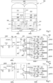
- FIG. 4 is an electrical diagram of a control circuit 400 of the photosite 100 of the figure 1 according to one embodiment.
- the circuit 400 is for example more precisely used in the case where the photosite 100 is implemented as a photosite 100Z adapted to capture blue light and infrared radiation.
- the control circuit 400 comprises a first level 400A, dedicated to the collection of the photogenerated charges in the first and second photosensitive zones 103 and 107 of the photosite 100Z, and a second level 400B, dedicated to the storage and reading of the charges coming from the first level 400A.
- the vertical transfer grid VEGA connects the cathode of the first pinched photodiode D1 to the cathode of the second pinched photodiode D2.
- the VEGA vertical transfer grid makes it possible to transfer photogenerated charges in photodiode D1 to photodiode D2.
- the transfer transistor MTGRST symbolized in Figure 4 by a switch, connects the cathode of the second pinched diode D2 to a node 401 for applying a potential VRT for supplying the photosite 100Z.
- the VRT potential is for example used as a reset potential.
- the MTG transfer transistor symbolized in Figure 4 by a switch, connects the cathode of diode D2 to a first charge storage node SN1.
- the MTG transistor allows the transfer of charges from photodiode D2 to node SN1.
- the node SN1 is for example connected to the zone 117 for collecting photogenerated charges in the first and second photosensitive zones 103 and 107.
- the node SN1 is part of a circuit 450 for copying, or transferring, the potential present at node SN1 on another charge storage node SN2.
- circuit 450 includes an MRST switch, for example a MOS transistor, connecting node SN1 to node 401 for applying the power supply potential VRT.
- the MRST switch makes it possible, for example, to reset the node SN1 by applying the VRT potential to it.
- the node SN1 is connected to a gate electrode of an MSF transistor of circuit 450, for example a MOS transistor, whose drain and source electrodes are respectively connected to the node 401 for applying the potential VRT and to the second node SN2 charge storage.
- the transistor MSF mounted as a voltage follower, allows for example to copy, on the node SN2, the voltage present at the node SN1, to within one gate-source voltage.
- the node SN2 is connected to a drain electrode of another transistor MB of the circuit 450, for example a MOS transistor, the source and gate electrodes of which are respectively connected to a node 403 of application of a reference potential, for example the ground, and to a node 405 for applying a potential Vb, for example associated with a common bias voltage of the circuit 400.
- the transistor MB is, in this example, mounted as a current source and allows the MSF transistor to be supplied with a constant current.
- the second level 400B of circuit 400 comprises four branches SIGZ, RSTZ, RSTB and SIGB each connecting the node SN2 of circuit 450 to a column Vx1.
- Column Vx1 is for example connected to a reading circuit, not shown in Figure 4 , located at the foot of the column.
- the switches and transistors of the SIGZ, RSTZ, RSTB and SIGB branches of circuit 400 are MOS transistors.
- the switches MSMPSIGZ, MSMPRSTZ, MSMPRSTB, MSMPSIGB are used as multiplexing switches between the node SN2 and the corresponding capacitive element C1, C2, C3, C4, allowing for example write access to these capacitive elements.
- the MOS transistors MSFSIGZ, MSFRSTZ, MSFRSTB, MSFSIGB are mounted as voltage followers and are for example used to copy onto their source, up to a gate-source voltage, the voltage stored by the capacitive element C1, C2, C3, C4 corresponding.
- the MRDSIGZ, MRDRSTZ, MRDRSTB, MRDSIGB switches are used as connection switches to the Vx1 column and make it possible to apply, on the Vx1 column, the voltage of source of the corresponding transistor MSFSIGZ, MSFRSTZ, MSFRSTB, MSFSIGB.
- the control circuit 400 advantageously makes it possible to simultaneously integrate photogenerated charges in the photosensitive zones 103 and 107 of the photodiodes D1 and D2, to sample the photogenerated charges in the photodiode D2 in parallel with the integration in the photodiodes D1 and D2 and to successively read, via the same electrical path, signals making it possible to reconstruct a depth image and a 2D image of a scene.
- control circuit 400 is compatible with operation of the image sensor in so-called global shutter mode.
- the person skilled in the art is capable of adapting the circuit 400 to make it compatible with operation of the image sensor in so-called rolling shutter mode.
- FIG. 5 is an electrical diagram of a control circuit 500 of the photosite 100 of the figure 1 according to another embodiment.
- the 500 circuit of the Figure 5 includes elements in common with circuit 400 of the figure 4 . These common elements will not be described again in detail below.
- the circuit 500 is for example more precisely used in the case where the photosite 100 is implemented as a photosite 100G adapted to capture green light.
- circuit 500 comprises a first level 500A identical to the first level 400A of circuit 400.
- circuit 500 further comprises a second level 500B.
- the second level 500B of the circuit 500 differs for example from the second level 400B of the circuit 400 in that the second level 500B of the circuit 500 comprises only two branches SIGG and RSTG each connecting the node SN2 of the circuit 450 to a column Vx2, for example different from column Vx1.
- the SIGG and RSTG branches of circuit 500 have, for example, structures similar to those of the SIGB and RSTB branches, respectively, of circuit 400 of the Figure 4 .
- the switches and transistors of the SIGG and RSTG branches of circuit 500 are MOS transistors.
- the transistors MSMPSIGG, MSMPRSTG, MSFSIGG, MSFRSTG, MRDSIGG and MRDRSTG have for example functions similar to those previously exposed for the transistors MSMPSIGB, MSMPRSTB, MSFSIGB, MSFRSTB, MRDSIGB and MRDRSTB, respectively.
- circuit 500 is used to control a 100G photosite adapted to capture green light
- the person skilled in the art is capable of adapting the circuit 500 to control a photosite adapted to capture red light. More precisely, a circuit identical to circuit 500 could be used.
- control circuits 400 and 500 using the same supply voltage VRT on each branch SIGZ, RSTZ, SIGB, RSTB, SIGG and RSTG.
- VRT supply voltage
- the second levels 400B and 500B of which comprise, for each capacitor C1, C2, C3, C4, C5, C6, a transistor MSFSIGZ, MSFRSTZ, MSFRSTB, MSFSIGB, MSFSIGG, MSFRSTG whose gate is connected to the one of the terminals of the corresponding capacity and whose source is connected to the corresponding column Vx1, Vx2 by a switch MRDSIGZ, MRDRSTZ, MRDRSTB, MRDSIGB, MRDSIGG, MRDRSTG.
- FIG. 6 is a timing diagram illustrating a mode of implementation of a method of controlling the photosites 100Z and 100G of the image sensor 300 of the Figure 3 respectively controlled by circuits 400 and 500 of figures 4 and 5 .
- each control signal has high and low states.
- the switch is closed, or the transistor is on, when the corresponding control signal is in the high state and the switch is open, or the transistor is blocked, when the corresponding control signal is in the state down.
- This example is however not limiting, the person skilled in the art being able to adapt what is described in relation to the Figure 6 in case the switch is closed when the corresponding control signal is low and open when the corresponding control signal is high.
- each photosite 100G, 100Z the charges are thus evacuated from the photodiode D1 by transferring them to the photodiode D2 and the charges are evacuated from the photodiode D2 by transferring them to the node 401 for applying the power supply potential VRT via the MTGRST switch.
- the node SN1 of each photosite 100G, 100Z is reset by application of the potential VRT via the switch MRST.
- the potential present at node SN1 after reset is written in the storage capacitor C2 via the transistor MSMPRSTZ. In this example, all other switches are in the open state between times t0 and t1.
- the signal RST1 controlling the MRST switches of the photosites 100G and 100Z is switched to the low state, the signals TGRSTZ, TGRSTG, MODE and SMPRSTZ being maintained in the high state. This has the effect of opening the MRST switches and storing the VRT potential at the SN1 nodes of the photosites 100G and 100Z.
- the signals TGRSTZ, TGRSTG, MODE and SMPRSTZ are switched to the low state.
- a SAM sampling phase of the charges photogenerated in photodiode D2 of photosite 100Z is carried out. More precisely, the charges photogenerated in the photodiode D2 of the photosite 100Z are transferred periodically to the node SN1 by controlling the transfer transistor MTG of the photosite 100Z to the on state then to the off state periodically.
- Diode D2 is reset periodically by controlling the transfer transistor MTGRST of photosite 100Z to the on state then to the off state during the phases where the transistor MTG is in the off state.
- the signal TGRSTZ has a duty cycle equal to approximately 3/4 and the signal TGZ has a duty cycle equal to approximately 1/4.
- Three other photosites of the image sensor 300 for example 100Z photosites neighboring the 100Z photosite considered, presenting TGRSTZ and TGZ signals phase shifted by ⁇ /2, ⁇ and 3 ⁇ /2 with respect to the TGRSTZ and TGZ signals illustrated in Figure 6 can be used to sample infrared radiation and return to the value of the phase shift ⁇ .
- two other photosites presenting TGRSTZ and TGZ signals each phase shifted by 2 ⁇ /3 and 4 ⁇ /3 relative to the TGRSTZ and TGZ signals of the 100Z photosite for example 100Z photosites neighboring the 100Z photosite considered, can be used to sample infrared radiation.
- an INT integration phase also begins in photodiode D1 of photosite 100Z and in photodiodes D1 and D2 of photosite 100G.
- the sentence integration INT ends at a time t4, after time t3.
- the TGRSTZ signal is switched to the high state and the TGZ signal is switched to the low state.
- the signal SMPSIGZ is first switched to the high state then to the low state.
- the reset potentials applied to the SN1 nodes of the photosites 100Z and 100G are stored in the capacitors C3 and C6, respectively.
- the signals TGZ, TGG and MODE are simultaneously switched to the high state, then simultaneously switched to the low state.
- the charges stored in photodiodes D1 of photosites 100Z and 100G are thus transferred into photodiode D2.
- photodiode D2 has previously been emptied of its charges photogenerated by infrared radiation.
- the charges photogenerated in the photodiode D1 are added to the charges photogenerated in photodiode D2.
- the charges located in the photodiode D2 of each photosite 100Z, 100G are also transferred to the node SN1.
- the TGRSTZ and TGRSTG signals are kept low during these operations.
- the signals SMPSIGB and SMPSIGG are then simultaneously switched to the high state, then simultaneously switched to the low state to write and store, in the capacitors C4 and C5, the voltages of the nodes SN1 (within one gate-source voltage) of the photosites 100Z and 100G, obtained following the transfer of charges on these nodes.
- the signals TGRSTZ and TGRSTG of the photosites 100Z and 100G are simultaneously switched to the high state to reset the photodiodes D2 by evacuating additional photogenerated charges, likely to fill the photodiode D2.
- the SMPSIGB and SMPSIGG signals are then switched low, while the TGRSTZ and TGRSTG signals are held high.
- the capacities connected to the same column Vx1, Vx2 are read successively while the capacities connected to different columns Vx1, Vx2 are read simultaneously. After each copy on one of the columns Vx1, Vx2, the voltages are for example stored at the bottom of the column by read circuits.
- FIG. 7 is an electrical diagram of a circuit 700 for controlling four photosites of the type of photosite 100 of the figure 1 according to one embodiment.
- FIG 7 we have more precisely represented a 100R photosite, adapted to capture mainly red light, two 100G photosites, adapted to capture mainly green light, and a 100Z photosite adapted to capture mainly blue light and infrared radiation.
- the photosites 100R, 100G and 100Z are for example identical or similar to the photosite 100.
- the photosites 100R, 100G, 100Z respectively comprise transfer transistors MTGR, MTGG, MTGZ similar to the transfer transistor MTG of the photosite 100.
- the transistors MTGR, MTGB and MTGZ are each symbolized by a switch, one terminal of which is connected to the cathode of the photodiode D2 and another terminal of which is connected to the node SN1 of circuit 450 previously described in relation to the Figure 4 .
- the node SN1 is connected to the source terminal of the MRST transistor and to the gate terminal of the MSF transistor.
- the drain terminals of the transistors MRST and MSF are each connected to the node 401 for applying the potential VRT.
- the source terminal of the transistor MSF is connected to the drain terminal of the transistor MB, the source terminal of the transistor MB being connected to node 403.
- the MRST, MSF and MB transistors are for example distributed in the control circuits of the photosites 100R, 100G and 100Z. More precisely, in the example shown, the transistor MRST is part of the control circuit of the photosite 100R, the transistor MSF is part of the control circuit of one of the photosites 100G and the transistor MB is part of the photosite control circuit 100Z.
- the control circuit of the other 100G photosite may include an unused MD transistor (“dummy”, in English). This makes it possible, for example, to provide identical or similar control circuits for all the photosites 100R, 100G and 100Z of the sensor. The production of the image sensor is thus facilitated.
- control circuit 700 illustrated in Figure 7 is due to the fact that it makes it possible to implement a photosite architecture with four transistors, called “4T”, instead of a photosite architecture with six transistors, called “6T”. This results in a saving in space and cost.
- the node SN2 of circuit 450 can be connected at a level identical or similar to the second level 400B of circuit 400 previously described in relation to the figure 4 .
- the person skilled in the art is able to deduce the operation of the control circuit 700 from the Figure 7 from the information provided above in relation to the figures 4 And 6 .
- FIG 8 is a schematic and partial top view of an image sensor photosite 800 according to another embodiment.
- the photosite 800 of the figure 8 includes common elements with photosite 100 of the figure 1 . These common elements will not be described again below.
- the photosite 800 of the figure 8 differs from photosite 100 of the figure 1 in that the photosite 800 comprises, in addition to the transfer transistor MTGRST, two other transfer transistors MTG1 and MTG2 identical or similar to the transfer transistor MTG of the photosite 100.
- the transistor MTG2 comprises a zone 817 for collecting photogenerated charges in the second photosensitive zone 107 and a horizontal transfer gate 819 identical or similar, respectively, to zone 117 and to gate 119 of the MTG1 transistor.
- the transistors MTG1, MTG2 and MTGRST are for example, as illustrated in figure 8 , arranged in three corners of the square formed by the peripheral insulation trench 111 of the photosite 800.
- the vertical transfer gate VEGA comprises three disjoint insulation trenches 115 extending laterally between the gates of the transistors MTG1, MTG2 and MTGRST.
- the geometry of the photosite 800 illustrated in figure 8 is not restrictive, the person skilled in the art being able to provide any geometry suitable for the integration of three transfer transistors inside the same photosite.
- An advantage of the photosite 800 is that it allows two samples of the infrared light signal received to be captured using the same depth image. This makes it possible to gain even more in resolution, or in the number of images useful for capturing all of the samples, compared to photosite 100.
- FIG. 9 is an electrical diagram of a circuit 900 for controlling the photosite 800 of the figure 8 according to one embodiment.
- circuit 900 comprises two circuits 901 and 902, for example each identical or similar to circuit 450 of circuit 400 of the Figure 4 . More precisely, in this example, each circuit 901, 902 comprises a node SN11, SN12 similar to the node SN1 of circuit 450 of the Figure 4 and another node SN21, SN22 similar to node SN2 of circuit 450. In the example illustrated in Figure 9 , the nodes SN11 and SN12 of circuits 901 and 902 are respectively connected to the transfer transistors MTG1 and MTG2 of the photosite 800, for example to zones 117 and 817 of the photosite 800.
- circuit 900 further comprises branches SIGZ1, RSTZ1, RSTB and SIGB connecting node SN21 of circuit 901 to a column Vx and branches SIGZ2 and RSTZ2 connecting node SN22 to column Vx.
- the branches SIGZ1 and SIGZ2 of circuit 900 are for example identical or similar to the branch SIGZ of circuit 400 of the Figure 4 and the branches RSTZ1 and RSTZ2 of circuit 900 are for example identical or similar to the branch RSTZ of circuit 400.
- the branches RSTB and SIGB of circuit 900 are for example identical to the branches RSTB and SIGB of circuit 400.
- the person skilled in the art is able to deduce the operation of the control circuit 900 from the Figure 9 from the operation of the control circuit 400 of the figure 4 previously described in relation to the figures 4 And 6 .
- the transfer transistors MTG1 and MTG2 are controlled so that each transistor MTG1, MTG2 is on for a quarter of the signal period.
- transistor MTGRST is on while MTG1 and MTG2 are off. This advantageously makes it possible to acquire two samples per photosite 800 using the same depth image.
- FIG. 10 is a schematic and partial top view of an image sensor photosite 1000 according to yet another embodiment.
- FIG 11A is a sectional view, according to plan AA of the Figure 10 , from photosite 1000 of the Figure 10 .
- the photosite 1000 of Figures 10 and 11A includes common elements with photosite 100 of Figures 1, 2A and 2B . These common elements will not be described again below.
- the photosite 1000 of Figures 10 and 11A differs from photosite 100 of figures 1, 2A and 2B in that the photosite 1000 comprises a third photosensitive zone 1003 formed in the semiconductor substrate 101 and interposed between the first and second photosensitive zones 103 and 107.
- the third photosensitive zone 1003 is located directly above the first and second photosensitive zones 103 and 107 (above the first photosensitive zone 103 and below the second photosensitive zone 107, in the orientation of the Figure 11A ). Seen from above, the third photosensitive zone 1003 has for example a circumference of substantially rectangular shape.
- the third photosensitive zone 1003 has for example lateral dimensions smaller than those of the first photosensitive zone 103. More precisely, in top view, the rectangle formed by the third photosensitive zone 1003 extends between the trenches 115 of the VEGA grid and between the two opposite walls of the peripheral insulation trench 111 perpendicular to the trenches 115.
- the third photosensitive zone 1003 is for example formed in a seventh region 1005 of the substrate 101 doped with the first type of conductivity, type N in this example, and presenting a doping level N5.
- the doping level N5 of the seventh region 1005 of the substrate 101 is for example higher than the doping level N1 of the first region 105 and lower than the doping level N2 of the second region 109.
- the seventh region 1005 of the substrate 101 is in contact, via its lower face, with the upper face of the first underlying region 105 and in contact, via its upper face, with the lower face of the second overlying region 109.
- the third photosensitive zone 1003 is substantially in contact, via its lower face, with the upper face of the underlying first photosensitive zone 103 and substantially in contact, by its upper face, with the lower face of the second overlying photosensitive zone 107.
- the third photosensitive zone 1003 is for example part of a third photosensitive diode D3, for example a pinched photodiode having a pinching voltage Vpin3.
- the pinch voltage Vpin3 of the third photodiode D3 is greater than the pinch voltage Vpin1 of the first photodiode D1 and lower than the pinch voltage Vpin2 of the second photodiode D2.
- Each photosensitive zone 103, 107, 1003 of the photosite 1000 is for example intended to collect incident photons, during illumination phases of the image sensor of which the photosite 100 is a part, and to convert these photons into electron-hole pairs.
- the first photosensitive zone 103 is adapted to capture light in a first range of wavelengths
- the second photosensitive zone 107 is adapted to capture light in a second range of wavelengths, different from the first wavelength range
- the third photosensitive zone 1003 is adapted to capture light in a third wavelength range.
- the third wavelength range includes for example the first and second wavelength ranges.
- the third wavelength range may be between the first and second wavelength ranges.
- the first and second photosensitive zones 103 and 107 are for example intended to capture respectively 2D images and depth images of a scene.
- the first photosensitive zone 103 of the photosite 1000 is adapted to capture visible light, for example blue light
- the second photosensitive zone 107 of the photosite 1000 is adapted to capture infrared radiation, for example a radiation near infrared, when the photosite 1000 is illuminated from the side of its lower face 101B.
- the third photosensitive zone 1003 of the photosite 1000 is then, for example, adapted to capture both visible light and near infrared radiation.
- the vertical transfer grid VEGA2 comprises two disjoint insulation trenches 1015, for example capacitive insulation trenches.
- each insulation trench 1015 of the vertical transfer gate VEGA2 extends vertically in the thickness of the semiconductor substrate 101 from the upper face 101T of the substrate 101 to the third photosensitive zone 1003, and partially penetrates into the third zone photosensitive 1003 to a depth less than that of the VEGA vertical transfer grid.
- each insulation trench 1015 is interrupted in the thickness of the seventh region 1005 of the substrate 101 and does not open into the first region 105 of the substrate 101.
- each insulation trench 1015 completely passes through the second region 109 of the substrate 101 and partially penetrates in the seventh region 1005.
- the insulation trenches 1015 form two plates substantially parallel to each other and bordering two opposite side faces of the second photosensitive zone 107.
- the insulation trenches 1015 are furthermore, seen from above, substantially parallel to two opposite sides of the peripheral insulation trench 111 and to the insulation trenches 115 of the vertical transfer grid VEGA.
- the vertical transfer grid VEGA surrounds the vertical transfer grid VEGA2, each trench 115 of the VEGA grid being interposed between a trench 1015 of the VEGA2 grid and a wall of the trench 111.
- each insulation trench 1015 of the VEGA2 vertical transfer grid has for example a structure similar to that of the insulation trenches 115 of the VEGA vertical transfer grid. More precisely, although this was not detailed in Figures 10 and 11A , each insulation trench 1015 comprises for example an electrically conductive region, for example made of polycrystalline silicon or a metal, for example copper, or a metal alloy. In addition, each trench 1015 comprises for example an electrically insulating layer covering the side walls and the lower face of the electrically conductive region. The electrically conductive region of each insulation trench 1015 is for example electrically isolated from the electrically conductive region of the trenches 115 and the peripheral insulation trench 111. This makes it possible, for example, to polarize the electrically conductive regions of the insulation trenches 1015 independently of the electrically conductive region of the trenches 115 and the peripheral insulation trench 111.
- the first charge collection zone 117 of the photosite 1000 is for example common to the charges photogenerated in the first, second and third photosensitive zones 103, 107 and 1003.
- the photosite 1000 is for example associated with a control circuit identical or similar to the control circuit 400 of the figure 4 .
- the person skilled in the art is capable of deducing the operation of the photosite 1000 from the Figures 10 and 11A from the operation of photosite 100 of figures 1, 2A and 2B previously described in relation to the figures 4 And 6 .
- the temporal evolution of the control signals is for example analogous to that previously described in relation to the chronogram of the Figure 6 , but includes an additional step of elimination, in a case where the third wavelength range includes the first and second wavelength ranges, or of transfer, in a case where the third wavelength range is between the first and second wavelength ranges, photogenerated charges in the third photosensitive zone 1003.
- the elimination or transfer step occurs for example after reading, on the node SN1, the charges photogenerated by infrared radiation and before the transfer of the charges photogenerated in the photodiode D1 to the node SN1, for example before switching to the high state of the MODE signal at time t4.
- the vertical transfer gate VEGA2 is for example switched to the on state to transfer the charges from the third photosensitive zone 1003 towards the photodiode D2 then towards the node 401 for applying the potential VRT, for example by opening the transistor MTGRST or by successively opening the transistor MTG then the transistor MRST.
- Adapting the operation to the case where the step prior to time t4 is a transfer step is within the reach of those skilled in the art based on the above indications.
- regions 105 and 109 of the substrate 101 in which the first and second photosensitive zones 103 and 107 are formed are doped with the same type of conductivity, type N in this example
- regions 105 and 109 present opposite types of conduction For example, region 105 could be doped with the first type of conductivity, type N in this example, and region 109 could be doped with the second type of conductivity, type P in this example.
- the transfer of charges from the first photosensitive zone 103 to the second photosensitive zone 107 would take place not in the volume, as in the case where the regions 105 and 109 are of the same type of conductivity, but through channels located along the sides of the trenches 115 of the VEGA vertical transfer grid.
- the first photosensitive zone 103 is adapted to capture mainly blue light
- the first photosensitive zone 103 is adapted to capture mainly green light.
Abstract
La présente description concerne un capteur d'images comprenant une pluralité de photosites (100) formés dans et sur un substrat semiconducteur (101), chaque photosite comportant :
- une première zone photosensible (103) formée dans le substrat semiconducteur et adaptée à capter de la lumière dans une première gamme de longueurs d'onde ;
- une deuxième zone photosensible (107) formée dans le substrat semiconducteur à l'aplomb de la première zone photosensible (103) et adaptée à capter de la lumière dans une deuxième gamme de longueurs d'onde, différente de la première gamme de longueurs d'onde ;
- une première zone (117) de collecte de charges photogénérées dans les première et deuxième zones photosensibles, disposée du côté d'une face (101T) du substrat opposée à la première zone photosensible (103) ;
- une première grille de transfert (VEGA), s'étendant verticalement depuis la première zone photosensible (103) jusqu'à ladite face (101T), adaptée à transférer les charges photogénérées dans la première zone photosensible (103) vers la deuxième zone photosensible (107) ; et
- une deuxième grille de transfert (119), s'étendant horizontalement sur ladite face (101T) à l'aplomb de la deuxième zone photosensible (107), adaptée à transférer les charges photogénérées depuis la deuxième zone photosensible (107) vers la première zone de collecte de charges (117).

- a first photosensitive zone (103) formed in the semiconductor substrate and adapted to capture light in a first wavelength range;
- a second photosensitive zone (107) formed in the semiconductor substrate directly above the first photosensitive zone (103) and adapted to capture light in a second range of wavelengths, different from the first range of lengths d 'wave ;
- a first zone (117) for collecting photogenerated charges in the first and second photosensitive zones, arranged on the side of a face (101T) of the substrate opposite to the first photosensitive zone (103);
- a first transfer grid (VEGA), extending vertically from the first photosensitive zone (103) to said face (101T), adapted to transfer the photogenerated charges in the first photosensitive zone (103) to the second photosensitive zone (107); And
- a second transfer grid (119), extending horizontally on said face (101T) directly above the second photosensitive zone (107), adapted to transfer the photogenerated charges from the second photosensitive zone (107) to the first charge collection zone (117).
Description
La présente description concerne de façon générale le domaine des dispositifs d'acquisition d'images. La présente description concerne plus particulièrement des dispositifs d'acquisition d'images adaptés à acquérir une image 2D et une image de profondeur d'une scène au moyen d'un même réseau de pixels.The present description generally concerns the field of image acquisition devices. The present description relates more particularly to image acquisition devices adapted to acquire a 2D image and a depth image of a scene by means of the same pixel array.
On connaît des dispositifs d'acquisition d'images capables d'acquérir une image 2D et une image de profondeur d'une scène. On connaît notamment des dispositifs comportant des pixels d'image 2D et des pixels de profondeur faisant partie d'un même réseau de pixels d'un capteur d'images.Image acquisition devices capable of acquiring a 2D image and a depth image of a scene are known. In particular, devices are known comprising 2D image pixels and depth pixels forming part of the same pixel array of an image sensor.
Il existe un besoin d'améliorer les dispositifs d'acquisition d'une image 2D et d'une image de profondeur d'une scène existants. Il serait plus précisément souhaitable de faciliter l'intégration de pixels de profondeur dans un réseau de pixels d'un capteur d'images adapté à acquérir des images 2D et des images de profondeur.There is a need to improve existing devices for acquiring a 2D image and a depth image of a scene. More specifically, it would be desirable to facilitate the integration of depth pixels into a pixel array of an image sensor adapted to acquire 2D images and depth images.
Un objet d'un mode de réalisation est de pallier tout ou partie des inconvénients des dispositifs d'acquisition d'une image 2D et d'une image de profondeur d'une scène connus. Un mode de réalisation a plus précisément pour objectif de faciliter l'intégration de pixels de profondeur dans un réseau de pixels d'un capteur d'images adapté à acquérir des images 2D et des images de profondeur.An object of one embodiment is to overcome all or part of the drawbacks of known devices for acquiring a 2D image and a depth image of a scene. One embodiment more precisely aims to facilitate the integration of depth pixels into a pixel array of an image sensor adapted to acquire 2D images and depth images.
Pour cela, un mode de réalisation prévoit un capteur d'images comprenant une pluralité de photosites formés dans et sur un substrat semiconducteur, chaque photosite comportant :
- une première zone photosensible formée dans le substrat semiconducteur et adaptée à capter de la lumière dans une première gamme de longueurs d'onde ;
- une deuxième zone photosensible formée dans le substrat semiconducteur à l'aplomb de la première zone photosensible et adaptée à capter de la lumière dans une deuxième gamme de longueurs d'onde, différente de la première gamme de longueurs d'onde ;
- une première zone de collecte de charges photogénérées dans les première et deuxième zones photosensibles, disposée du côté d'une face du substrat opposée à la première zone photosensible ;
- une première grille de transfert, s'étendant verticalement depuis la première zone photosensible jusqu'à ladite face, adaptée à transférer les charges photogénérées dans la première zone photosensible vers la deuxième zone photosensible ; et
- une deuxième grille de transfert, s'étendant horizontalement sur ladite face à l'aplomb de la deuxième zone photosensible, adaptée à transférer les charges photogénérées depuis la deuxième zone photosensible vers la première zone de collecte de charges.
- a first photosensitive zone formed in the semiconductor substrate and adapted to capture light in a first wavelength range;
- a second photosensitive zone formed in the semiconductor substrate directly above the first photosensitive zone and adapted to capture light in a second wavelength range, different from the first wavelength range;
- a first zone for collecting photogenerated charges in the first and second photosensitive zones, arranged on the side of a face of the substrate opposite to the first photosensitive zone;
- a first transfer grid, extending vertically from the first photosensitive zone to said face, adapted to transfer the photogenerated charges in the first photosensitive zone to the second photosensitive zone; And
- a second transfer grid, extending horizontally on said face directly above the second photosensitive zone, adapted to transfer the photogenerated charges from the second photosensitive zone to the first charge collection zone.
Selon un mode de réalisation, chaque photosite comporte en outre :
- au moins une deuxième zone de collecte de charges photogénérées dans la deuxième zone photosensible, disposée du côté de ladite face ; et
- au moins une troisième grille de transfert s'étendant latéralement, sur ladite face, à l'aplomb de la deuxième zone photosensible.
- at least a second zone for collecting photogenerated charges in the second photosensitive zone, arranged on the side of said face; And
- at least a third transfer grid extending laterally, on said face, directly above the second photosensitive zone.
Selon un mode de réalisation, chaque photosite comporte en outre :
- une troisième zone photosensible, interposée entre les première et deuxième zones photosensibles ; et
- une quatrième grille de transfert s'étendant verticalement, depuis la troisième zone photosensible, jusqu'à ladite face et adaptée à transférer les charges photogénérées dans la troisième zone photosensible vers la deuxième zone photosensible.
- a third photosensitive zone, interposed between the first and second photosensitive zones; And
- a fourth transfer grid extending vertically, from the third photosensitive zone, to said face and adapted to transfer the photogenerated charges in the third photosensitive zone to the second photosensitive zone.
Selon un mode de réalisation, la première zone de collecte de charges est commune aux charges photogénérées dans les première, deuxième et troisième zones photosensibles.According to one embodiment, the first charge collection zone is common to the charges photogenerated in the first, second and third photosensitive zones.
Selon un mode de réalisation, la première grille de transfert entoure la quatrième grille de transfert.According to one embodiment, the first transfer grid surrounds the fourth transfer grid.
Selon un mode de réalisation, chaque photosite comporte en outre une tranchée d'isolation périphérique s'étendant verticalement dans le substrat semiconducteur, depuis ladite face, et délimitant latéralement la première zone photosensible.According to one embodiment, each photosite further comprises a peripheral insulation trench extending vertically in the semiconductor substrate, from said face, and laterally delimiting the first photosensitive zone.
Selon un mode de réalisation, chaque photosite comporte en outre un circuit de commande configuré pour appliquer alternativement, sur la première grille de transfert :
- un premier potentiel adapté à bloquer un transfert de charges depuis la première zone photosensible vers la deuxième zone photosensible ; et
- un deuxième potentiel, différent du premier potentiel, adapté à permettre un transfert de charges depuis la première zone photosensible vers la deuxième zone photosensible.
- a first potential adapted to block a transfer of charges from the first photosensitive zone to the second photosensitive zone; And
- a second potential, different from the first potential, adapted to allow a transfer of charges from the first photosensitive zone to the second photosensitive zone.
Selon un mode de réalisation, le circuit de commande est configuré pour appliquer alternativement, sur la deuxième grille de transfert :
- un troisième potentiel adapté à bloquer un transfert de charges depuis la deuxième zone photosensible vers la première zone de stockage de charges ; et
- un quatrième potentiel, différent du troisième potentiel, adapté à permettre un transfert de charges depuis la deuxième zone photosensible vers la première zone de stockage de charges.
- a third potential adapted to block a transfer of charges from the second photosensitive zone to the first charge storage zone; And
- a fourth potential, different from the third potential, adapted to allow a transfer of charges from the second photosensitive zone to the first charge storage zone.
Selon un mode de réalisation, le capteur comprend en outre une cinquième grille de transfert s'étendant horizontalement sur ladite face à l'aplomb de la deuxième zone photosensible, la cinquième grille de transfert étant adaptée à transférer des charges photogénérées depuis la deuxième zone photosensible vers une deuxième zone de collecte de charges.According to one embodiment, the sensor further comprises a fifth transfer grid extending horizontally on said face directly above the second photosensitive zone, the fifth transfer grid being adapted to transfer photogenerated charges from the second photosensitive zone towards a second charge collection zone.
Selon un mode de réalisation, les deuxième et cinquième grilles de transfert sont successivement ouvertes lors d'une phase d'échantillonnage de charges photogénérées dans la deuxième zone photosensible.According to one embodiment, the second and fifth transfer gates are successively opened during a sampling phase of photogenerated charges in the second photosensitive zone.
Selon un mode de réalisation, les deuxième et cinquième grilles de transfert sont reliées entre elles par un commutateur.According to one embodiment, the second and fifth transfer gates are interconnected by a switch.
Selon un mode de réalisation, les premières et deuxièmes zones photosensibles des photosites du capteur sont destinées à capturer respectivement une image 2D et une image de profondeur d'une scène.According to one embodiment, the first and second photosensitive zones of the photosites of the sensor are intended to respectively capture a 2D image and a depth image of a scene.
Selon un mode de réalisation, les première et deuxième zones photosensibles sont dopées du même type de conductivité.According to one embodiment, the first and second photosensitive zones are doped with the same type of conductivity.
Selon un mode de réalisation, la première zone photosensible est dopée d'un premier type de conductivité et la deuxième zone photosensible est dopée d'un deuxième type de conductivité, opposé au premier type de conductivité.According to one embodiment, the first photosensitive zone is doped with a first type of conductivity and the second photosensitive zone is doped with a second type of conductivity, opposite to the first type of conductivity.
Un mode de réalisation prévoit un dispositif comprenant :
- un capteur d'images tel que décrit ;
- une source d'émission d'un rayonnement infrarouge ; et
- un circuit de commande de la source d'émission du rayonnement infrarouge et du capteur d'images.
- an image sensor as described;
- an infrared radiation emission source; And
- a circuit for controlling the infrared radiation emission source and the image sensor.
Ces caractéristiques et avantages, ainsi que d'autres, seront exposés en détail dans la description suivante de modes de réalisation particuliers faite à titre non limitatif en relation avec les figures jointes parmi lesquelles :
- la
figure 1 est une vue de dessus, schématique et partielle, d'un photosite de capteur d'images selon un mode de réalisation ; - la
figure 2A est une vue en coupe, selon le plan AA de lafigure 1 , du photosite de lafigure 1 ; - la
figure 2B est une vue en coupe, selon le plan BB de lafigure 1 , du photosite de lafigure 1 ; - la
figure 3 est une vue en coupe, schématique et partielle, d'un capteur d'images comprenant plusieurs photosites du type du photosite de lafigure 1 selon un mode de réalisation ; - la
figure 4 est un schéma électrique d'un circuit de commande du photosite de lafigure 1 selon un mode de réalisation ; - la
figure 5 est un schéma électrique d'un circuit de commande du photosite de lafigure 1 selon un autre mode de réalisation ; - la
figure 6 est chronogramme illustrant un mode de mise en oeuvre d'un procédé de commande de photosites du capteur d'images de lafigure 3 ; - la
figure 7 est un schéma électrique d'un circuit de commande de quatre photosites du type du photosite de lafigure 1 selon un mode de réalisation ; - la
figure 8 est une vue de dessus, schématique et partielle, d'un photosite de capteur d'images selon un autre mode de réalisation ; - la
figure 9 est un schéma électrique d'un circuit de commande du photosite de lafigure 8 selon un mode de réalisation ; - la
figure 10 est une vue de dessus, schématique et partielle, d'un photosite de capteur d'images selon encore un autre mode de réalisation ; et - la
figure 11A est une vue en coupe, selon le plan AA de lafigure 10 , du photosite de lafigure 10 .
- there
figure 1 is a schematic and partial top view of an image sensor photosite according to one embodiment; - there
Figure 2A is a sectional view, according to plan AA of thefigure 1 , from the photosite of thefigure 1 ; - there
Figure 2B is a sectional view, according to plan BB of thefigure 1 , from the photosite of thefigure 1 ; - there
Figure 3 is a schematic and partial sectional view of an image sensor comprising several photosites of the photosite type of thefigure 1 according to one embodiment; - there
Figure 4 is an electrical diagram of a photosite control circuit of thefigure 1 according to one embodiment; - there
figure 5 is an electrical diagram of a photosite control circuit of thefigure 1 according to another embodiment; - there
Figure 6 is a chronogram illustrating a mode of implementation of a method of controlling photosites of the image sensor of theFigure 3 ; - there
Figure 7 is an electrical diagram of a control circuit for four photosites of the photosite type of thefigure 1 according to one embodiment; - there
figure 8 is a schematic and partial top view of an image sensor photosite according to another embodiment; - there
Figure 9 is an electrical diagram of a photosite control circuit of thefigure 8 according to one embodiment; - there
Figure 10 is a schematic and partial top view of an image sensor photosite according to yet another embodiment; And - there
Figure 11A is a sectional view, according to plan AA of theFigure 10 , from the photosite of theFigure 10 .
De mêmes éléments ont été désignés par de mêmes références dans les différentes figures. En particulier, les éléments structurels et/ou fonctionnels communs aux différents modes de réalisation peuvent présenter les mêmes références et peuvent disposer de propriétés structurelles, dimensionnelles et matérielles identiques.The same elements have been designated by the same references in the different figures. In particular, the structural and/or functional elements common to the different embodiments may have the same references and may have identical structural, dimensional and material properties.
Par souci de clarté, seuls les étapes et éléments utiles à la compréhension des modes de réalisation décrits ont été représentés et sont détaillés. En particulier, les circuits de lecture, ou décodeurs colonnes, les circuits de commande, ou décodeurs lignes, et les applications dans lesquelles peuvent être prévus des capteurs d'images n'ont pas été détaillés, les modes de réalisation et variantes décrits étant compatibles avec les circuits de lecture et les circuits de commande des capteurs d'images usuels, ainsi qu'avec les applications usuelles mettant en oeuvre des capteurs d'images.For the sake of clarity, only the steps and elements useful for understanding the embodiments described have been represented and are detailed. In particular, the reading circuits, or column decoders, the control circuits, or line decoders, and the applications in which image sensors can be provided have not been detailed, the embodiments and variants described being compatible with the reading circuits and the control circuits of usual image sensors, as well as with the usual applications using image sensors.
En outre, la polarisation du caisson MOS et les couches de passivation situées le long des flancs des grilles de transfert verticales et des tranchées d'isolation ne sont pas détaillées.In addition, the polarization of the MOS box and the passivation layers located along the sides of the vertical transfer grids and the insulation trenches are not detailed.
Sauf précision contraire, lorsque l'on fait référence à deux éléments connectés entre eux, cela signifie directement connectés sans éléments intermédiaires autres que des conducteurs, et lorsque l'on fait référence à deux éléments reliés (en anglais « coupled ») entre eux, cela signifie que ces deux éléments peuvent être connectés ou être reliés par l'intermédiaire d'un ou plusieurs autres éléments.Unless otherwise specified, when we refer to two elements connected together, this means directly connected without intermediate elements other than conductors, and when we refer to two elements connected (in English “coupled”) between them, this means that these two elements can be connected or be linked through one or more other elements.
Dans la description qui suit, « transmittance d'une couche » désigne un rapport entre l'intensité du rayonnement sortant de la couche et l'intensité du rayonnement entrant dans la couche. Dans la suite de la description, une couche ou un film est dit opaque à un rayonnement lorsque la transmittance du rayonnement au travers de la couche ou du film est inférieure à 10 %. Dans la suite de la description, une couche ou un film est dit transparent à un rayonnement lorsque la transmittance du rayonnement au travers de la couche ou du film est supérieure à 10 %.In the following description, “transmittance of a layer” designates a ratio between the intensity of the radiation leaving the layer and the intensity of the radiation entering the layer. In the remainder of the description, a layer or film is said to be opaque to radiation when the transmittance of the radiation through the layer or film is less than 10%. In the remainder of the description, a layer or film is said to be transparent to radiation when the transmittance of the radiation through the layer or film is greater than 10%.
Dans la suite de la description, « lumière visible » désigne un rayonnement électromagnétique dont la longueur d'onde est comprise entre 380 et 780 nm et « rayonnement infrarouge » désigne un rayonnement électromagnétique dont la longueur d'onde est comprise entre 780 nm et 15 µm. En outre, « rayonnement infrarouge proche » désigne plus précisément un rayonnement électromagnétique dont la longueur d'onde est comprise entre 750 nm et 1,1 µm.In the remainder of the description, “visible light” designates electromagnetic radiation whose wavelength is between 380 and 780 nm and “infrared radiation” designates electromagnetic radiation whose wavelength is between 780 nm and 15 µm. In addition, “near infrared radiation” refers more precisely to electromagnetic radiation whose wavelength is between 750 nm and 1.1 µm.
Un pixel d'une image correspond à l'élément unitaire de l'image captée par un capteur d'images. Lorsque le capteur d'images est un capteur d'images couleur, il comprend en général, pour chaque pixel de l'image couleur à acquérir, un groupe d'au moins trois photosites. Chacun de ces trois photosites effectue l'acquisition d'un rayonnement lumineux sensiblement dans une seule couleur (par exemple le rouge, le vert ou le bleu), par exemple dans une plage de longueurs d'onde inférieure à 100 nm. Lorsque le capteur d'images est un capteur d'images de profondeur, il peut comprendre, pour chaque pixel de l'image de profondeur à acquérir, un ou plusieurs photosites permettant chacun d'acquérir une partie de l'information de profondeur.A pixel of an image corresponds to the unit element of the image captured by an image sensor. When the image sensor is a color image sensor, it generally includes, for each pixel of the color image to be acquired, a group of at least three photosites. Each of these three photosites acquires light radiation substantially in a single color (for example red, green or blue), for example in a wavelength range of less than 100 nm. When the image sensor is a depth image sensor, it can comprise, for each pixel of the depth image to be acquired, one or more photosites each allowing part of the depth information to be acquired.
Dans la description qui suit, lorsque l'on fait référence à des qualificatifs de position absolue, tels que les termes « avant », « arrière », « haut », « bas », « gauche », « droite », etc., ou relative, tels que les termes « dessus », « dessous », « supérieur », « inférieur », etc., ou à des qualificatifs d'orientation, tels que les termes « horizontal », « vertical », etc., il est fait référence sauf précision contraire à l'orientation des figures.In the following description, when referring to absolute position qualifiers, such as the terms "front", "back", "top", "bottom", "left", "right", etc., or relative, such as the terms “above”, “below”, “superior”, “lower”, etc., or to qualifiers of orientation, such as the terms “horizontal”, “vertical”, etc., it is referred to unless otherwise specified in the orientation of the figures.
Sauf précision contraire, les expressions « environ », « approximativement », « sensiblement », et « de l'ordre de » signifient à 10 % près, de préférence à 5 % près.Unless otherwise specified, the expressions “approximately”, “approximately”, “substantially”, and “of the order of” mean to the nearest 10%, preferably to the nearest 5%.
La
Dans l'exemple représenté, le photosite 100 est formé dans et sur un substrat semiconducteur 101, par exemple en silicium. À titre d'exemple, le substrat 101 présente une épaisseur comprise entre 3 et 20 µm.In the example shown, the
Dans cet exemple, le photosite 100 comporte une première zone photosensible 103 formée dans le substrat semiconducteur 101. Comme illustré en
La première zone photosensible 103 peut par exemple constituer une première diode photosensible D1, ou photodiode, par exemple une photodiode pincée présentant une tension de pincement Vpin1.The first
Dans l'exemple représenté, le photosite 100 comporte en outre une deuxième zone photosensible 107 formée dans le substrat semiconducteur 101. La deuxième zone photosensible 107 est située à l'aplomb de la première zone photosensible 103 (au-dessus de la première zone photosensible 103, dans l'orientation des
La deuxième zone photosensible 107 peut par exemple constituer une deuxième diode photosensible D2, par exemple une photodiode pincée présentant une tension de pincement Vpin2. Dans cet exemple, la tension de pincement Vpin2 de la deuxième photodiode D2 est supérieure à la tension de pincement Vpin1 de la première photodiode D1.The second
Chaque zone photosensible 103, 107 est par exemple destinée à collecter des photons incidents, lors de phases d'illumination du capteur d'images dont fait partie le photosite 100, et à convertir ces photons en paires électron-trou. Dans cet exemple, la première zone photosensible 103 est adaptée à capter de la lumière dans une première gamme de longueurs d'onde et la deuxième zone photosensible 107 est adaptée à capter de la lumière dans une deuxième gamme de longueurs d'onde, différente de la première gamme de longueurs d'onde. Les première et deuxième zones photosensibles 103 et 107 sont par exemple destinées à capturer respectivement des images 2D et des images de profondeur d'une scène. À titre d'exemple, la première zone photosensible 103 du photosite 100 est adaptée à capter de la lumière visible, par exemple de la lumière bleue, et la deuxième zone photosensible 107 du photosite 100 est adaptée à capter un rayonnement infrarouge, par exemple un rayonnement infrarouge proche, lorsque le photosite 100 est illuminé du côté de sa face inférieure 101B.Each
Dans un cas où les première et deuxième zones photosensibles 103 et 107 sont en le même matériau, par exemple le silicium, la lumière visible et le rayonnement infrarouge sont absorbés majoritairement à des profondeurs différentes dans le substrat semiconducteur 101 depuis sa face inférieure 101B. Dans ce cas, la profondeur d'absorption majoritaire de la lumière visible est inférieure à celle du rayonnement infrarouge. La deuxième zone photosensible 107 peut par exemple présenter une épaisseur supérieure à celle de la première zone photosensible 103 afin d'optimiser l'absorption du rayonnement infrarouge dans la deuxième zone photosensible 107.In a case where the first and second
Dans l'exemple représenté, le photosite 100 comporte en outre une tranchée d'isolation périphérique 111, par exemple une tranchée d'isolation capacitive, délimitant latéralement la première zone photosensible 103. Plus précisément, dans cet exemple, la tranchée d'isolation périphérique 111 borde toutes les faces latérales de la première zone photosensible 103 et présente, en vue de dessus, un pourtour de forme sensiblement carrée.In the example shown, the
La tranchée d'isolation périphérique 111 permet d'isoler électriquement les première et deuxième zones photosensibles 103 et 107 du photosite 100 par rapport aux zones photosensibles des photosites voisins, non représentés en
La tranchée d'isolation périphérique 111 présente par exemple une largeur comprise entre 30 et 600 nm, et une profondeur comprise entre 5 et 20 µm. Dans l'exemple illustré en
Bien que cela n'ait pas été détaillé en
Dans l'exemple illustré en
- un premier potentiel adapté à bloquer un transfert de charges depuis la première zone photosensible 103 vers la deuxième
zone photosensible 107 ; ou - un deuxième potentiel, différent du premier potentiel, adapté à permettre un transfert de charges depuis la première zone photosensible 103 vers la deuxième
zone photosensible 107.
- a first potential adapted to block a transfer of charges from the first
photosensitive zone 103 to the secondphotosensitive zone 107; Or - a second potential, different from the first potential, adapted to allow a transfer of charges from the first
photosensitive zone 103 to the secondphotosensitive zone 107.
Dans cet exemple, la grille de transfert verticale VEGA comprend deux tranchées d'isolation 115 disjointes, par exemple des tranchées d'isolation capacitives. Comme illustré en
Dans l'exemple représenté, les tranchées d'isolation 115 forment deux plaques sensiblement parallèles entre elles et bordant deux faces latérales opposées de la deuxième zone photosensible 107. Dans cet exemple, les tranchées d'isolation 115 sont en outre, vues de dessus, sensiblement parallèles à deux côtés opposés de la tranchée d'isolation périphérique 111.In the example shown, the
De manière générale, la grille de transfert verticale VEGA comprend au moins des première et deuxième plaques parallèles entre elles, chaque plaque comprenant par exemple une plaque conductrice revêtue d'une couche isolante, la deuxième zone photosensible 107 s'étendant latéralement depuis une face de la première plaque jusqu'à une face de la deuxième plaque située en regard de la première plaque. Dit autrement, la deuxième zone photosensible 107 s'étend à l'intérieur d'un volume délimité latéralement par au moins deux plaques faisant partie de la grille de transfert verticale VEGA.Generally, the VEGA vertical transfer grid comprises at least first and second plates parallel to each other, each plate comprising for example a conductive plate coated with an insulating layer, the second
Dans cet exemple, les tensions de pincement Vpin1 et Vpin2 des diodes D1 et D2 peuvent être ajustées en modifiant les niveaux de dopage N1 et N2 des zones photosensibles 103 et 107. Les tensions Vpin1 et Vpin2 peuvent en outre être ajustées en modifiant respectivement une distance entre les deux murs opposés de la tranchée d'isolation périphérique 111 parallèles aux tranchées d'isolation 115 et la largeur de la grille de transfert verticale VEGA, autrement dit la distance entre les deux tranchées d'isolation 115. Les tensions Vpin1 et Vpin2 dépendent en outre d'une tension de polarisation d'une couche d'inversion passivant les flancs de la tranchée 111, pour la zone photosensible 103, et des tranchées 115, pour la zone photosensible 107. Cette tension de polarisation est par exemple identique pour les deux zones photosensibles 103 et 107. Dans cet exemple, la tension de polarisation de la couche d'inversion ne permet pas d'ajuster les tensions de pincement Vpin1 et Vpin2 indépendamment l'une de l'autre.In this example, the pinch voltages Vpin1 and Vpin2 of the diodes D1 and D2 can be adjusted by modifying the doping levels N1 and N2 of the
Chaque tranchée d'isolation 115 de la grille de transfert verticale VEGA présente par exemple une structure analogue à celle de la tranchée d'isolation périphérique 111. Plus précisément, bien que cela n'ait pas été détaillé en
La région électriquement conductrice de chaque tranchée d'isolation 115 est par exemple électriquement isolée de la région électriquement conductrice de la tranchée d'isolation périphérique 111. Cela permet par exemple de polariser les régions électriquement conductrices des tranchées d'isolation 115 indépendamment de la région électriquement conductrice de la tranchée d'isolation périphérique 111.The electrically conductive region of each
Dans l'exemple représenté, le photosite 100 comporte en outre une même zone 117 de collecte des charges photogénérées dans les première et deuxième zones photosensibles 103 et 107, disposée du côté de la face supérieure 101T du substrat semiconducteur 101 opposée à la première zone photosensible 103. Dans l'orientation de la
Dans cet exemple, le photosite 100 comporte en outre une grille de transfert horizontale 119 adaptée à transférer les charges depuis la deuxième zone photosensible 107 vers la zone 117 de collecte de charges. Plus précisément, un circuit de commande du photosite 100 peut être utilisé pour appliquer alternativement, sur la grille de transfert horizontale 119 :
- un troisième potentiel adapté à bloquer un transfert de charges depuis la deuxième
zone photosensible 107 vers la zone de collecte de charges 117 ; ou - un quatrième potentiel, différent du troisième potentiel, adapté à permettre un transfert de charges depuis la deuxième
zone photosensible 107 vers la zone de collecte de charges 117.
- a third potential adapted to block a transfer of charges from the second
photosensitive zone 107 to thecharge collection zone 117; Or - a fourth potential, different from the third potential, adapted to allow a transfer of charges from the second
photosensitive zone 107 to thecharge collection zone 117.
Dans l'exemple illustré, la grille de transfert horizontale 119 s'étend horizontalement sur la face supérieure 101T du substrat semiconducteur 101 à l'aplomb de la deuxième zone photosensible 107. La grille de transfert 119 comporte plus précisément une couche 121 électriquement isolante, par exemple en oxyde de silicium, revêtant une partie de la face supérieure 101T du substrat semiconducteur 101 et une couche 123 électriquement conductrice, par exemple en silicium polycristallin dopé, revêtant une face supérieure de la couche 121 électriquement isolante.In the example illustrated, the
Dans l'exemple représenté, le substrat semiconducteur 101 comporte en outre une quatrième région 125 dopée d'un deuxième type de conductivité, le type P dans cet exemple, opposé au premier type de conductivité et présentant un niveau de dopage P1. Dans cet exemple, la quatrième région 125 s'étend verticalement dans l'épaisseur du substrat 101 depuis la face supérieure 101T du substrat 101 et jusqu'à une profondeur inférieure à celle de la zone 117 de collecte de charges. La quatrième région 125 s'étend par exemple horizontalement entre les tranchées d'isolation 115 de la grille de transfert verticale VEGA.In the example shown, the
Le substrat 101 comporte par exemple en outre une cinquième région 127 dopée du premier type de conductivité, le type N dans cet exemple, et présentant un niveau de dopage N3. Le niveau de dopage N3 de la cinquième région 127 est par exemple supérieur au niveau de dopage N2 de la deuxième région 109 et inférieur au niveau de dopage N4 de la zone 117. La cinquième région 127 est par exemple située à l'aplomb de la quatrième région 125. Dans cet exemple, la quatrième région 125 du substrat 101 est en contact, par sa face inférieure, avec la face supérieure de la cinquième région 127 sous-jacente. Dans cet exemple, la cinquième région 127 s'étend verticalement dans l'épaisseur du substrat 101 depuis la face inférieure de la quatrième région 125 et jusqu'à une profondeur inférieure à celle de la zone 117 de collecte de charges.The
Dans l'exemple représenté, le substrat semiconducteur 101 comporte en outre une sixième région 129 dopée du deuxième type de conductivité, le type P dans cet exemple, et présentant un niveau de dopage P2. Dans cet exemple, la sixième région 129 s'étend verticalement dans l'épaisseur du substrat 101 depuis la face supérieure 101T du substrat 101 et jusqu'à une profondeur supérieure à celle de la zone 117 de collecte de charges et de la cinquième région 127 du substrat 101. La sixième région 129 est par exemple interposée entre les quatrième et cinquième régions 125 et 127, d'une part, et la zone 117 de collecte de charges, d'autre part. En outre, la sixième région 129 peut, comme dans l'exemple illustré en
Dans cet exemple, la couche électriquement conductrice 123 et la couche électriquement isolante 121 de la grille de transfert 119 correspondent respectivement à une électrode de grille et à un isolant de grille d'un transistor MTG de transfert des charges photogénérées dans les première et deuxième zones photosensibles 103 et 107, par exemple un transistor MOS (de l'anglais « Metal Oxide Semiconductor », métal oxyde semiconducteur). En outre, les troisième, cinquième et sixième régions 117, 127 et 129 du substrat 101 correspondent respectivement à des régions de drain, de source et de canal du transistor MTG. La quatrième région 125 du substrat 101 permet par exemple de passiver la surface de la cinquième région 127.In this example, the electrically
À titre d'exemple, les première, deuxième, troisième, quatrième, cinquième et sixième régions 105, 109, 117, 125, 127 et 129 sont formées par implantation ionique dans le substrat semiconducteur 101.For example, the first, second, third, fourth, fifth and
Dans l'exemple représenté, le photosite 100 comporte en outre une autre grille de transfert horizontale 131 adaptée à transférer des charges depuis la deuxième zone photosensible 107 vers un noeud de réinitialisation, non représenté, du photosite 100. La grille de transfert 131 présente par exemple une structure identique ou similaire à celle de la grille de transfert 119 et ne sera pas décrite en détail ci-après. Plus précisément, la grille de transfert 131 fait par exemple partie d'un autre transistor de transfert MTGRST, par exemple un transistor MOS de réinitialisation des zones photosensibles 103 et 107. Le transistor MTGRST de réinitialisation présente par exemple une structure identique ou similaire à celle du transistor de transfert MTG. En particulier, le transistor MTGRST comporte par exemple une zone 132 de collecte de charges identique ou analogue à la zone 117 de collecte de charges du transistor MTG. Dans l'exemple représenté, la deuxième zone de collecte de charges 132 s'étend latéralement sur la face supérieure 101T du substrat 101 à l'aplomb de la deuxième zone photosensible 107.In the example shown, the
Dans l'exemple illustré, le photosite 100 comporte en outre des tranchées d'isolation 133 situées de part et d'autre de la deuxième zone photosensible 107. Les tranchées d'isolation 133 s'étendent verticalement dans l'épaisseur du substrat semiconducteur 101, depuis sa face supérieure 101T, jusqu'à une profondeur par exemple inférieure à l'épaisseur de la zone 117 de collecte de charges. Dans cet exemple, les tranchées d'isolation 133 s'étendent en outre horizontalement dans une direction sensiblement perpendiculaire aux plaques formées par les tranchées d'isolation 115 de la grille de transfert verticale VEGA. Dans l'exemple représenté, le fond de chaque tranchée 133 est sur et en contact avec la région 129. À titre d'exemple, les tranchées d'isolation 133 sont des tranchées de type STI (de l'anglais « Shallow Trench Isolation »), ou tranchées peu profondes d'isolation, et présentent par exemple une profondeur de l'ordre de 300 nm.In the example illustrated, the
La
Dans l'exemple représenté, les photosites 100G et 100Z du capteur 300 sont sur et en contact, du côté de leur face 101T (la face inférieure, dans l'orientation de la
Dans l'exemple du capteur d'images 300, la première zone photosensible 103 du photosite 100Z est adaptée à capter de la lumière visible, par exemple de la lumière bleue, et la deuxième zone photosensible 107 du photosite 100Z est adaptée à capter un rayonnement infrarouge, par exemple un rayonnement infrarouge proche.In the example of the
Dans cet exemple, les zones photosensibles 103 et 107 du photosite 100G sont toutes les deux adaptées à capter de la lumière visible, par exemple de la lumière verte. À titre d'exemple, la grille de transfert verticale VEGA du photosite 100G peut être en permanence commandée à l'état passant. Dans ce cas, les première et deuxième zones photosensibles 103 et 107 du photosite 100G sont par exemple réunies, ou mutualisées, formant ainsi une unique zone photosensible 303.In this example, the
Dans l'exemple représenté, chaque photosite 100G, 100Z est revêtu, du côté de sa face 101B (la face supérieure, dans l'orientation de la
Dans cet exemple, la couche 305 du photosite 100G est revêtue d'une couche 307 de résine. À titre d'exemple, la couche de résine 307 agit comme un filtre couleur adapté à ne laisser passer que de la lumière verte, par exemple dans la plage de longueurs d'onde de 510 à 570 nm. En outre, la couche 305 du photosite 100Z est revêtue d'une couche 309 de résine différente de la couche 307. À titre d'exemple, la couche de résine 309 agit comme un filtre couleur adapté à ne laisser passer que de la lumière bleue, par exemple dans la plage de longueurs d'onde de 430 à 490 nm.In this example,
Dans l'exemple représenté, la couche de résine 307 du photosite 100G est revêtue d'une autre couche 311 de résine. À titre d'exemple, la couche de résine 311 agit comme un filtre adapté à laisser passer de la lumière visible, par exemple dans la plage de longueurs d'onde de 400 à 700 nm, la couche 311 étant par exemple opaque à une gamme ou bande de longueurs d'onde centrée sur environ 940 nm. En outre, la couche de résine 309 du photosite 100Z est revêtue d'une couche 313 de résine. La couche 313 est par exemple transparente à la lumière visible et aux rayonnements infrarouges et permet de compenser une différence de hauteur entre la couche 309 du photosite 100Z et la couche 311 du photosite 100G.In the example shown, the
Dans l'exemple représenté, les couches 305, 307 et 311 du photosite 100G sont séparées des couches 305, 309 et 313 du photosite 100Z par une barrière verticale 315 d'isolation optique. La barrière verticale 315 permet par exemple d'éviter les phénomènes de diaphotie (« optical cross-talk », en anglais) entre les différents photosites 100G, 100Z du capteur 300.In the example shown, layers 305, 307 and 311 of
Dans cet exemple, chaque photosite 100G, 100Z est en outre surmonté d'une microlentille 317.In this example, each photosite 100G, 100Z is also surmounted by a
La couche 313 est par exemple en le même matériau que les microlentilles 317. À titre de variante, la couche 313 est en dioxyde de silicium (SiO2).
Comme illustré en
Pour l'acquisition d'images 2D couleur, les photosites du capteur d'images 300 sont par exemple répartis en groupes élémentaires de quatre photosites, chaque groupe comprenant plus précisément un photosite 100Z adapté à capter de la lumière bleue et un rayonnement infrarouge, appelé photosite bleu et de profondeur, deux photosites 100G adaptés à capter uniquement de la lumière verte, appelés photosites verts, et un photosite adapté à capter uniquement de la lumière rouge, appelé photosite rouge. Le photosite rouge présente par exemple une structure analogue à celle précédemment décrite pour le photosite vert 100G. Plus précisément, le photosite rouge diffère par exemple du photosite vert 100G en ce que la couche de résine 307 du photosite rouge est adaptée à ne laisser passer que de la lumière rouge, par exemple dans la plage de longueurs d'onde de 620 à 700 nm. À titre d'exemple, les photosites du capteur d'images 300 sont arrangés selon une matrice de Bayer.For the acquisition of 2D color images, the photosites of the
Le capteur d'images 300 est par exemple adapté à acquérir, outre des images 2D couleur d'une scène, des images de profondeur de la scène. Les images de profondeur sont par exemple acquises par le capteur d'images 300 en mettant en oeuvre une mesure de distance par de temps de vol indirect (« indirect Time of Flight » - iToF, en anglais). Pour cela, un rayonnement, ou signal, infrarouge incident modulé en amplitude à une fréquence de modulation Fmod est par exemple émis par une source en direction de la scène. Le rayonnement, ou signal, réfléchi par la scène, présentant par rapport au rayonnement incident un déphasage Δϕ, est capturé par les photosites 100Z du capteur d'images 300. Pour chaque photosite, le déphasage Δϕ du rayonnement capturé par le photosite est fonction de la distance entre le dispositif et un point ou une région de la scène vue par le photosite.The
À titre d'exemple, pour chaque pixel d'une image de profondeur à acquérir par le capteur d'images 300, un groupe de quatre photosites 100Z voisins est utilisé pour échantillonner le signal réfléchi par la scène, afin d'estimer le déphasage Δϕ (module 2π). Plus précisément, les quatre photosites 100Z sont par exemple configurés pour acquérir, durant chaque période de modulation (fréquence Fmod) du signal réfléchi, quatre échantillons successifs correspondant chacun à une quantité de charges photogénérées dans la deuxième zone photosensible 107 du photosite 100Z pendant une durée égale environ à un quart de la période du signal réfléchi, puis transférées vers une zone de stockage. Ces quatre échantillons sont cumulés ou intégrés sur plusieurs périodes du signal réfléchi, par exemple sur plusieurs milliers ou millions de périodes, et permettent de remonter au déphasage Δϕ entre l'onde incidente et l'onde réfléchie.For example, for each pixel of a depth image to be acquired by the
À titre de variante, on peut prévoir d'utiliser, pour chaque pixel de l'image de profondeur à acquérir, seulement trois photosites 100Z voisins. Dans ce cas, les trois photosites 100Z sont par exemple configurés pour acquérir, durant chaque période du signal réfléchi, trois échantillons successifs correspondant chacun à une quantité de charges photogénérées pendant des fenêtres d'échantillonnage égales chacune à environ un tiers de la période du signal réfléchi.As a variant, we can plan to use, for each pixel of the depth image to be acquired, only three neighboring 100Z photosites. In this case, the three
À titre de variante, on peut prévoir d'utiliser par exemple deux photosites 100Z pour acquérir les quatre échantillons, chacun des deux photosites 100Z adaptés à former un même pixel de l'image de profondeur étant par exemple utilisé pour acquérir deux sous-images successives. Plus précisément, les deux photosites 100Z sont par exemple configurés pour acquérir, lors d'une première phase d'acquisition, les échantillons correspondant à des premier et deuxième quarts de la période de modulation du signal lumineux, et, lors d'une deuxième phase d'acquisition, les échantillons correspondant à des troisième et quatrième quarts de la période de modulation du signal lumineux. La combinaison des deux sous-images permet d'obtenir les quatre échantillons à partir desquels le déphasage Δϕ est calculé pour former l'image de profondeur.As a variant, it is possible to use for example two 100Z photosites to acquire the four samples, each of the two 100Z photosites adapted to forming the same pixel of the depth image being for example used to acquire two successive sub-images . More precisely, the two
L'acquisition de plusieurs échantillons par un même photosite permet avantageusement d'augmenter la résolution du capteur. À titre d'exemple, par rapport à un cas où chaque photosite est configuré pour acquérir un seul échantillon, on peut augmenter la résolution du capteur en prévoyant que chaque photosite soit configuré pour acquérir deux ou trois échantillons, chaque pixel de l'image de profondeur étant obtenu au moyen de deux photosites ou d'un seul photosite, respectivement. En outre, l'acquisition de plusieurs échantillons par un même photosite permet avantageusement d'augmenter la cadence de prise de vue. À titre d'exemple, dans un cas où deux photosites sont utilisés pour reconstituer chaque pixel de l'image de profondeur, deux images sont utilisées pour calculer la distance si chaque photosite capture un seul échantillon tandis qu'une seule image est utilisée pour calculer la distance si chaque photosite capture deux échantillons. Toutefois, le fait d'acquérir plusieurs échantillons par un même photosite tend à augmenter les dimensions du photosite.The acquisition of several samples by the same photosite advantageously makes it possible to increase the resolution of the sensor. For example, compared to a case where each photosite is configured to acquire a single sample, we can increase the resolution of the sensor by providing that each photosite is configured to acquire two or three samples, each pixel of the image depth being obtained by means of two photosites or a single photosite, respectively. In addition, the acquisition of several samples by the same photosite advantageously makes it possible to increase the shooting rate. As an example, in a case where two photosites are used to reconstitute each pixel of the depth image, two images are used to calculate the distance if each photosite captures a single sample while a single image is used to calculate the distance if each photosite captures two samples. However, acquiring several samples from the same photosite tends to increase the dimensions of the photosite.
La
Dans l'exemple illustré en
Dans le premier niveau 400A du circuit 400, la grille de transfert verticale VEGA relie la cathode de la première photodiode pincée D1 à la cathode de la deuxième photodiode pincée D2. La grille de transfert verticale VEGA permet de transférer des charges photogénérées dans la photodiode D1 vers la photodiode D2. En outre, dans cet exemple, le transistor de transfert MTGRST, symbolisé en
Dans cet exemple, le circuit 450 comporte un commutateur MRST, par exemple un transistor MOS, reliant le noeud SN1 au noeud 401 d'application du potentiel d'alimentation VRT. Le commutateur MRST permet par exemple de réinitialiser le noeud SN1 en lui appliquant le potentiel VRT. Dans l'exemple illustré en
Dans l'exemple représenté, le deuxième niveau 400B du circuit 400 comporte quatre branches SIGZ, RSTZ, RSTB et SIGB reliant chacune le noeud SN2 du circuit 450 à une colonne Vx1. La colonne Vx1 est par exemple connectée à un circuit de lecture, non représenté en
Dans cet exemple, les branches SIGZ, RSTZ, RSTB, SIGB comportent respectivement :
- un premier commutateur MSMPSIGZ, MSMPRSTZ, MSMPRSTB, MSMPSIGB reliant le noeud SN2 à un noeud VZSIG, VZRST, VBRST, VBSIG ;
- un élément capacitif C1, C2, C3, C4 comprenant une première borne connectée au noeud VZSIG, VZRST, VBRST, VBSIG et une deuxième borne connectée au noeud 403 d'application du potentiel de référence ;
- un transistor MSFSIGZ, MSFRSTZ, MSFRSTB, MSFSIGB comprenant une borne de grille connectée au noeud VZSIG, VZRST, VBRST, VBSIG et une borne de drain connectée au noeud 401 d'application du potentiel VRT ; et
- un deuxième commutateur MRDSIGZ, MRDRSTZ, MRDRSTB, MRDSIGB reliant une borne de source du transistor MSFSIGZ, MSFRSTZ, MSFRSTB, MSFSIGB à la colonne Vx1.
- a first switch MSMPSIGZ, MSMPRSTZ, MSMPRSTB, MSMPSIGB connecting the node SN2 to a node VZSIG, VZRST, VBRST, VBSIG;
- a capacitive element C1, C2, C3, C4 comprising a first terminal connected to the node VZSIG, VZRST, VBRST, VBSIG and a second terminal connected to the
node 403 for applying the reference potential; - a transistor MSFSIGZ, MSFRSTZ, MSFRSTB, MSFSIGB comprising a gate terminal connected to the node VZSIG, VZRST, VBRST, VBSIG and a drain terminal connected to the
node 401 for applying the potential VRT; And - a second switch MRDSIGZ, MRDRSTZ, MRDRSTB, MRDSIGB connecting a source terminal of the transistor MSFSIGZ, MSFRSTZ, MSFRSTB, MSFSIGB to column Vx1.
À titre d'exemple, les commutateurs et les transistors des branches SIGZ, RSTZ, RSTB et SIGB du circuit 400 sont des transistors MOS.For example, the switches and transistors of the SIGZ, RSTZ, RSTB and SIGB branches of
Dans cet exemple, les commutateurs MSMPSIGZ, MSMPRSTZ, MSMPRSTB, MSMPSIGB sont utilisés comme interrupteurs de multiplexage entre le noeud SN2 et l'élément capacitif C1, C2, C3, C4 correspondant, en permettant par exemple un accès en écriture à ces éléments capacitifs. Les transistors MOS MSFSIGZ, MSFRSTZ, MSFRSTB, MSFSIGB sont montés en suiveurs de tension et sont par exemple utilisés pour recopier sur leur source, à une tension grille-source près, la tension stockée par l'élément capacitif C1, C2, C3, C4 correspondant. Les commutateurs MRDSIGZ, MRDRSTZ, MRDRSTB, MRDSIGB sont utilisés comme interrupteurs de connexion à la colonne Vx1 et permettent d'appliquer, sur la colonne Vx1, la tension de source du transistor MSFSIGZ, MSFRSTZ, MSFRSTB, MSFSIGB correspondant.In this example, the switches MSMPSIGZ, MSMPRSTZ, MSMPRSTB, MSMPSIGB are used as multiplexing switches between the node SN2 and the corresponding capacitive element C1, C2, C3, C4, allowing for example write access to these capacitive elements. The MOS transistors MSFSIGZ, MSFRSTZ, MSFRSTB, MSFSIGB are mounted as voltage followers and are for example used to copy onto their source, up to a gate-source voltage, the voltage stored by the capacitive element C1, C2, C3, C4 corresponding. The MRDSIGZ, MRDRSTZ, MRDRSTB, MRDSIGB switches are used as connection switches to the Vx1 column and make it possible to apply, on the Vx1 column, the voltage of source of the corresponding transistor MSFSIGZ, MSFRSTZ, MSFRSTB, MSFSIGB.
Le circuit de commande 400 permet avantageusement d'intégrer simultanément des charges photogénérées dans les zones photosensibles 103 et 107 des photodiodes D1 et D2, d'échantillonner les charges photogénérées dans la photodiode D2 en parallèle de l'intégration dans les photodiodes D1 et D2 et de lire successivement, via un même chemin électrique, des signaux permettant de reconstituer une image de profondeur et une image 2D d'une scène.The
Dans l'exemple illustré en
La
Dans l'exemple représenté, le circuit 500 comprend un premier niveau 500A identique au premier niveau 400A du circuit 400. Dans cet exemple, le circuit 500 comprend en outre un deuxième niveau 500B. Le deuxième niveau 500B du circuit 500 diffère par exemple du deuxième niveau 400B du circuit 400 en ce que le deuxième niveau 500B du circuit 500 comporte seulement deux branches SIGG et RSTG reliant chacune le noeud SN2 du circuit 450 à une colonne Vx2, par exemple différente de la colonne Vx1. Les branches SIGG et RSTG du circuit 500 présentent par exemple des structures similaires à celles des branches SIGB et RSTB, respectivement, du circuit 400 de la
Plus précisément, dans cet exemple, les branches SIGG et RSTG comportent respectivement :
- un premier commutateur MSMPSIGG, MSMPRSTG reliant le noeud SN2 à un noeud VGSIG, VGRST ;
- un élément capacitif C5, C6 comprenant une première borne connectée au noeud VGSIG, VGRST et une deuxième borne connectée au noeud 403 d'application du potentiel de référence ;
- un transistor MSFSIGG, MSFRSTG comprenant une borne de grille connectée au noeud VGSIG, VGRST et une borne de drain connectée au noeud 401 d'application du potentiel VRT ; et
- un deuxième commutateur MRDSIGG, MRDRSTG reliant une borne de source du transistor MSFSIGG, MSFRSTG à la colonne Vx2.
- a first switch MSMPSIGG, MSMPRSTG connecting the node SN2 to a node VGSIG, VGRST;
- a capacitive element C5, C6 comprising a first terminal connected to the node VGSIG, VGRST and a second terminal connected to the
node 403 for applying the reference potential; - a transistor MSFSIGG, MSFRSTG comprising a gate terminal connected to the node VGSIG, VGRST and a drain terminal connected to the
node 401 for applying the potential VRT; And - a second switch MRDSIGG, MRDRSTG connecting a source terminal of the transistor MSFSIGG, MSFRSTG to column Vx2.
À titre d'exemple, les commutateurs et les transistors des branches SIGG et RSTG du circuit 500 sont des transistors MOS.For example, the switches and transistors of the SIGG and RSTG branches of
Les transistors MSMPSIGG, MSMPRSTG, MSFSIGG, MSFRSTG, MRDSIGG et MRDRSTG présentent par exemple des fonctions analogues à celles précédemment exposées pour les transistors MSMPSIGB, MSMPRSTB, MSFSIGB, MSFRSTB, MRDSIGB et MRDRSTB, respectivement.The transistors MSMPSIGG, MSMPRSTG, MSFSIGG, MSFRSTG, MRDSIGG and MRDRSTG have for example functions similar to those previously exposed for the transistors MSMPSIGB, MSMPRSTB, MSFSIGB, MSFRSTB, MRDSIGB and MRDRSTB, respectively.
Bien que l'on ait exposé ci-dessus en relation avec la
Dans un souci de simplification, on a exposé ci-dessus en relation avec les
En outre, on a exposé ci-dessus en relation avec les
La
Plus précisément, la
- d'un signal TGRSTZ de commande du transistor de transfert MTGRST du photosite 100Z ;
- d'un signal TGZ de commande du transistor de transfert MTG du photosite 100Z ;
- d'un signal TGRSTG de commande du transistor de transfert MTGRST du photosite 100G ;
- d'un signal TGG de commande du transistor de transfert MTG du photosite 100G ;
- d'un signal MODE de commande des grilles de transfert verticales VEGA des photosites
100Z et 100G ou, à titre de variante, de la grille de transfert verticale VEGA du photosite 100Z uniquement ; - d'un signal RST1 de commande des commutateurs MRST des photosites 100Z et 100G ;
- d'un signal SMPRSTZ de commande du commutateur MSMPRSTZ de la branche RSTZ du deuxième niveau 400B du
circuit 400 ; - d'un signal SMPSIGZ de commande du commutateur MSMPSIGZ de la branche SIGZ du deuxième niveau 400B du
circuit 400 ; - d'un signal SMPRSTB de commande du commutateur MSMPRSTB de la branche RSTB du deuxième niveau 400B du
circuit 400 ; - d'un signal SMPSIGB de commande du commutateur MSMPSIGB de la branche SIGB du deuxième niveau 400B du
circuit 400 ; - d'un signal SMPRSTG de commande du commutateur MSMPRSTG de la branche RSTG du deuxième niveau 500B du
circuit 500 ; - d'un signal SMPSIGG de commande du commutateur MSMPSIGG de la branche SIGG du deuxième niveau 500B du
circuit 500 ; - d'un signal RDRSTZ de commande du commutateur MRDRSTZ de la branche RSTZ du deuxième niveau 400B du
circuit 400 ; - d'un signal RDSIGZ de commande du commutateur MRDSIGZ de la branche SIGZ du deuxième niveau 400B du
circuit 400 ; - d'un signal RDRSTB de commande du commutateur MRDRSTB de la branche RSTB du deuxième niveau 400B du
circuit 400 ; - d'un signal RDSIGB de commande du commutateur MRDSIGB de la branche SIGB du deuxième niveau 400B du
circuit 400 ; - d'un signal RDRSTG de commande du commutateur MRDRSTG de la branche RSTG du deuxième niveau 500B du
circuit 500 ; et - d'un signal RDSIGG de commande du commutateur MRDSIGG de la branche SIGG du deuxième niveau 500B du
circuit 500.
- a signal TGRSTZ for controlling the transfer transistor MTGRST of the
photosite 100Z; - of a TGZ signal for controlling the transfer transistor MTG of
photosite 100Z; - a signal TGRSTG for controlling the transfer transistor MTGRST of the
photosite 100G; - a signal TGG for controlling the transfer transistor MTG of the
photosite 100G; - a MODE signal for controlling the VEGA vertical transfer grids of the 100Z and 100G photosites or, as a variant, the VEGA vertical transfer grid of the 100Z photosites only;
- a signal RST1 for controlling the MRST switches of the
photosites - a signal SMPRSTZ for controlling the switch MSMPRSTZ of the RSTZ branch of the
second level 400B of thecircuit 400; - a signal SMPSIGZ for controlling the switch MSMPSIGZ of the SIGZ branch of the
second level 400B ofcircuit 400; - a signal SMPRSTB for controlling the switch MSMPRSTB of the RSTB branch of the
second level 400B ofcircuit 400; - a signal SMPSIGB for controlling the switch MSMPSIGB of the SIGB branch of the
second level 400B ofcircuit 400; - a signal SMPRSTG for controlling the switch MSMPRSTG of the RSTG branch of the
second level 500B ofcircuit 500; - a signal SMPSIGG for controlling the switch MSMPSIGG of the SIGG branch of the
second level 500B ofcircuit 500; - a signal RDRSTZ for controlling the switch MRDRSTZ of the RSTZ branch of the
second level 400B of thecircuit 400; - a signal RDSIGZ for controlling the switch MRDSIGZ of the SIGZ branch of the
second level 400B of thecircuit 400; - a signal RDRSTB for controlling the switch MRDRSTB of the RSTB branch of the
second level 400B ofcircuit 400; - an RDSIGB signal for controlling the MRDSIGB switch of the SIGB branch of the
second level 400B of thecircuit 400; - a signal RDRSTG for controlling the switch MRDRSTG of the RSTG branch of the
second level 500B ofcircuit 500; And - of a signal RDSIGG for controlling the switch MRDSIGG of the SIGG branch of the
second level 500B ofcircuit 500.
Dans le procédé illustré en
Entre un instant t0 et un autre instant t1, postérieur à l'instant t0, les signaux TGRSTZ, TGRSTG, MODE, RST1 et SMPRSTZ sont à l'état haut. Dans chaque photosite 100G, 100Z, on évacue ainsi les charges de la photodiode D1 en les transférant vers la photodiode D2 et on évacue les charges de la photodiode D2 en les transférant vers le noeud 401 d'application du potentiel d'alimentation VRT via le commutateur MTGRST. En outre, le noeud SN1 de chaque photosite 100G, 100Z est réinitialisé par application du potentiel VRT via le commutateur MRST. Dans le photosite 100G, 100Z, le potentiel présent au noeud SN1 après réinitialisation est écrit dans la capacité de stockage C2 via le transistor MSMPRSTZ. Dans cet exemple, tous les autres commutateurs sont à l'état ouvert entre les instants t0 et t1.Between a time t0 and another time t1, subsequent to time t0, the signals TGRSTZ, TGRSTG, MODE, RST1 and SMPRSTZ are in the high state. In each photosite 100G, 100Z, the charges are thus evacuated from the photodiode D1 by transferring them to the photodiode D2 and the charges are evacuated from the photodiode D2 by transferring them to the
À l'instant t1, le signal RST1 de commande des commutateurs MRST des photosites 100G et 100Z est commuté vers l'état bas, les signaux TGRSTZ, TGRSTG, MODE et SMPRSTZ étant maintenus à l'état haut. Cela a pour effet d'ouvrir les commutateurs MRST et de mémoriser le potentiel VRT aux noeuds SN1 des photosites 100G et 100Z.At time t1, the signal RST1 controlling the MRST switches of the
À un instant t2, postérieur à l'instant t1, les signaux TGRSTZ, TGRSTG, MODE et SMPRSTZ sont commutés vers l'état bas. Entre l'instant t2 et un instant t3, postérieur à l'instant t2, on effectue une phase d'échantillonnage SAM des charges photogénérées dans la photodiode D2 du photosite 100Z. Plus précisément, les charges photogénérées dans la photodiode D2 du photosite 100Z sont transférées périodiquement vers le noeud SN1 en commandant le transistor de transfert MTG du photosite 100Z à l'état passant puis à l'état bloqué de façon périodique. La diode D2 est réinitialisée périodiquement en commandant le transistor de transfert MTGRST du photosite 100Z à l'état passant puis à l'état bloqué pendant les phases où le transistor MTG est à l'état bloqué.At a time t2, subsequent to time t1, the signals TGRSTZ, TGRSTG, MODE and SMPRSTZ are switched to the low state. Between time t2 and a time t3, subsequent to time t2, a SAM sampling phase of the charges photogenerated in photodiode D2 of
Dans l'exemple représenté, le signal TGRSTZ présente un rapport cyclique égal à environ 3/4 et le signal TGZ présente un rapport cyclique égal à environ 1/4. Trois autres photosites du capteur d'image 300, par exemple des photosites 100Z voisins du photosite 100Z considéré, présentant des signaux TGRSTZ et TGZ déphasés de π/2, π et 3π/2 par rapport aux signaux TGRSTZ et TGZ illustrés en
À l'instant t2 débute également une phase d'intégration INT dans la photodiode D1 du photosite 100Z et dans les photodiodes D1 et D2 du photosite 100G. La phase d'intégration INT s'achève à un instant t4, postérieur à l'instant t3. À l'instant t3, le signal TGRSTZ est commuté vers l'état haut et le signal TGZ est commuté vers l'état bas. On évacue ainsi, vers le noeud 401 d'application du potentiel VRT, des charges continuant d'être photogénérées dans la photodiode D2 sous l'effet de l'absorption du rayonnement infrarouge et/ou des charges résiduelles pouvant subsister dans la photodiode D2. Entre les instants t3 et t4, on commute d'abord le signal SMPSIGZ vers l'état haut puis vers l'état bas. Cela a pour effet de stocker, dans la capacité C1, la tension présente au noeud SN1 (à une tension grille-source près) obtenue suite à l'accumulation des charges sur ce noeud durant la phase d'échantillonnage SAM. On commute ensuite simultanément les signaux RST1, SMPRSTB et SMPRSTG vers l'état haut, puis on commute le signal RST1 vers l'état bas et enfin on commute les signaux SMPRSTB et SMPRSTG vers l'état bas. Cela permet de préparer la lecture des charges photogénérées par la lumière visible en procédant à la réinitialisation des noeuds SN1 des photosites 100Z et 100G pour que ceux-ci puissent ultérieurement recevoir les charges photogénérées dans la photodiode D1 du photosite 100Z et dans les photodiodes D1 et D2 du photosite 100G. Les potentiels de réinitialisation appliqués aux noeuds SN1 des photosites 100Z et 100G sont mémorisés dans les capacités C3 et C6, respectivement.At time t2 an INT integration phase also begins in photodiode D1 of
Entre l'instant t4 et un instant t5, postérieur à l'instant t4, les signaux TGZ, TGG et MODE sont simultanément commutés vers l'état haut, puis simultanément commutés vers l'état bas. Les charges stockées dans les photodiodes D1 des photosites 100Z et 100G sont ainsi transférées dans la photodiode D2. Dans le cas du photosite 100Z, la photodiode D2 a préalablement été vidée de ses charges photogénérées par le rayonnement infrarouge. Dans le cas du photosite 100G, les charges photogénérées dans la photodiode D1 s'ajoutent aux charges photogénérées dans la photodiode D2. Les charges se trouvant dans la photodiode D2 de chaque photosite 100Z, 100G sont en outre transférées au noeud SN1. Les signaux TGRSTZ et TGRSTG sont maintenus à l'état bas durant ces opérations.Between time t4 and a time t5, subsequent to time t4, the signals TGZ, TGG and MODE are simultaneously switched to the high state, then simultaneously switched to the low state. The charges stored in photodiodes D1 of
Les signaux SMPSIGB et SMPSIGG sont ensuite simultanément commutés vers l'état haut, puis simultanément commutés vers l'état bas pour écrire et stocker, dans les capacités C4 et C5, les tensions des noeuds SN1 (à une tension grille-source près) des photosites 100Z et 100G, obtenues suite aux transferts des charges sur ces noeuds. En outre, les signaux TGRSTZ et TGRSTG des photosites 100Z et 100G sont simultanément commutés vers l'état haut pour réinitialiser les photodiodes D2 en évacuant des charges photogénérées supplémentaires, susceptibles de remplir la photodiode D2. Les signaux SMPSIGB et SMPSIGG sont ensuite commutés vers l'état bas, tandis que les signaux TGRSTZ et TGRSTG sont maintenus à l'état haut.The signals SMPSIGB and SMPSIGG are then simultaneously switched to the high state, then simultaneously switched to the low state to write and store, in the capacitors C4 and C5, the voltages of the nodes SN1 (within one gate-source voltage) of the
Dans l'exemple représenté, entre un instant t6, postérieur à l'instant t5, et un instant t7, postérieur à l'instant t6, on effectue une phase de lecture TRANS durant laquelle les opérations suivantes sont successivement exécutées :
- le signal RDRSTZ est commuté vers l'état haut puis vers l'état bas, pour recopier la tension présente aux bornes de la capacité C2 sur la colonne Vx1 (à une tension grille-source près) ;
- le signal RDSIGZ est commuté vers l'état haut puis vers l'état bas, pour recopier la tension présente aux bornes de la capacité C1 sur la colonne Vx1 (à une tension grille-source près) ;
- les signaux RDRSTB, RDRSTG sont simultanément commutés vers l'état haut, puis simultanément commutés vers l'état bas, pour recopier les tensions présentes respectivement aux bornes des capacités C3, C5 sur les colonnes Vx1, Vx2 (à une tension grille-source près) ; et
- les signaux RDSIGB, RDSIGG sont simultanément commutés vers l'état haut, puis simultanément commutés vers l'état bas, pour recopier les tensions présentes respectivement aux bornes des capacités C4, C6 sur les colonnes Vx1, Vx2 (à une tension grille-source près).
- the signal RDRSTZ is switched to the high state then to the low state, to copy the voltage present across the capacitor C2 on the column Vx1 (within one gate-source voltage);
- the signal RDSIGZ is switched to the high state then to the low state, to copy the voltage present across the capacitor C1 on the column Vx1 (within one gate-source voltage);
- the signals RDRSTB, RDRSTG are simultaneously switched to the high state, then simultaneously switched to the low state, to copy the voltages present respectively at the terminals of capacitors C3, C5 on columns Vx1, Vx2 (within one gate-source voltage); And
- the signals RDSIGB, RDSIGG are simultaneously switched to the high state, then simultaneously switched to the low state, to copy the voltages present respectively at the terminals of the capacitors C4, C6 on the columns Vx1, Vx2 (within one gate-source voltage ).
Dans cet exemple, les capacités reliées à une même colonne Vx1, Vx2 sont lues successivement tandis que les capacités reliées à des colonnes Vx1, Vx2 différentes sont lues simultanément. Après chaque recopie sur l'une des colonnes Vx1, Vx2, les tensions sont par exemple stockées en pied de colonne par des circuits de lecture.In this example, the capacities connected to the same column Vx1, Vx2 are read successively while the capacities connected to different columns Vx1, Vx2 are read simultaneously. After each copy on one of the columns Vx1, Vx2, the voltages are for example stored at the bottom of the column by read circuits.
La
En
Plus précisément, le noeud SN1 est connecté à la borne de source du transistor MRST et à la borne de grille du transistor MSF. Les bornes de drain des transistors MRST et MSF sont connectées chacune au noeud 401 d'application du potentiel VRT. En outre, la borne de source du transistor MSF est connectée à la borne de drain du transistor MB, la borne de source du transistor MB étant connectée au noeud 403.More precisely, the node SN1 is connected to the source terminal of the MRST transistor and to the gate terminal of the MSF transistor. The drain terminals of the transistors MRST and MSF are each connected to the
Les transistors MRST, MSF et MB sont par exemple répartis dans les circuits de commande des photosites 100R, 100G et 100Z. Plus précisément, dans l'exemple représenté, le transistor MRST fait partie du circuit de commande du photosite 100R, le transistor MSF fait partie du circuit de commande de l'un des photosites 100G et le transistor MB fait partie du circuit de commande du photosite 100Z. À titre d'exemple, le circuit de commande de l'autre photosite 100G peut comporter un transistor MD non utilisé (« dummy », en anglais). Cela permet par exemple de prévoir des circuits de commande identiques ou similaires pour tous les photosites 100R, 100G et 100Z du capteur. La réalisation du capteur d'images est ainsi facilitée.The MRST, MSF and MB transistors are for example distributed in the control circuits of the
Un avantage du circuit de commande 700 illustré en
Bien que cela n'ait pas été illustré en
La
Plus précisément, dans l'exemple représenté, le transistor MTG2 comporte une zone 817 de collecte de charges photogénérées dans la deuxième zone photosensible 107 et une grille de transfert 819 horizontale identiques ou similaires, respectivement, à la zone 117 et à la grille 119 du transistor MTG1.More precisely, in the example shown, the transistor MTG2 comprises a
Afin d'optimiser l'espace disponible, les transistors MTG1, MTG2 et MTGRST sont par exemple, comme illustré en
Un avantage du photosite 800 tient au fait qu'il permet de capturer deux échantillons du signal lumineux infrarouge reçu au moyen d'une même image de profondeur. Cela permet de gagner encore davantage en résolution, ou en nombre d'images utiles pour la capture de la totalité des échantillons, par rapport au photosite 100.An advantage of the
La
Dans l'exemple représenté, le circuit 900 comprend deux circuits 901 et 902, par exemple identiques ou similaires chacun au circuit 450 du circuit 400 de la
Dans cet exemple, le circuit 900 comprend en outre des branches SIGZ1, RSTZ1, RSTB et SIGB reliant le noeud SN21 du circuit 901 à une colonne Vx et des branches SIGZ2 et RSTZ2 reliant le noeud SN22 à la colonne Vx. Les branches SIGZ1 et SIGZ2 du circuit 900 sont par exemple identiques ou similaires à la branche SIGZ du circuit 400 de la
La personne du métier est capable de déduire le fonctionnement du circuit de commande 900 de la
De façon optionnelle, le circuit 900 peut en outre comporter un commutateur SW, par exemple un transistor MOS, reliant le noeud SN11 du circuit 901 au noeud SN12 du circuit 902. Le commutateur SW relie par exemple le transistor MTG1 au transistor MTG2, le commutateur comportant par exemple plus précisément une borne connectée à la zone 117 et une autre borne connectée à la zone 817 du photosite 800. Dans ce cas, lorsque le transistor MTG1 est à l'état passant pour transférer les charges photogénérées dans la zone photosensible 103, dans le cas du photosite 100Z, ou dans les zones photosensibles 103 et 107, dans le cas des photosites 100G et 100R, à l'issue de la phase d'intégration INT, on peut commander le commutateur SW :
- soit à l'état ouvert (transistor bloqué) de sorte à transférer les charges photogénérées vers le noeud SN11 uniquement, le circuit de commande 900 présentant dans ce cas un fonctionnement similaire à celui du
circuit 400 ; ou - soit à l'état fermé (transistor passant), de sorte à répartir le transfert des charges photogénérées vers les noeuds SN11 et SN12, qui équivalent dans ce cas à un unique noeud présentant une capacité environ égale au double de la capacité d'un seul des noeuds SN11 et SN12.
- either in the open state (transistor blocked) so as to transfer the photogenerated charges to the node SN11 only, the
control circuit 900 presenting in this case an operation similar to that of thecircuit 400; Or - either in the closed state (transistor on), so as to distribute the transfer of the photogenerated charges towards the nodes SN11 and SN12, which in this case are equivalent to a single node having a capacity approximately equal to double the capacity of a single nodes SN11 and SN12.
Cela permet avantageusement de bénéficier d'une double dynamique, c'est-à-dire d'accéder à deux gammes d'un couple formé par les paramètres « gamme d'intensité lumineuse » et « précision ».This advantageously allows you to benefit from double dynamics, that is to say access to two ranges of a pair formed by the “light intensity range” and “precision” parameters.
La
Le photosite 1000 des
La troisième zone photosensible 1003 fait par exemple partie d'une troisième diode photosensible D3, par exemple une photodiode pincée présentant une tension de pincement Vpin3. Dans cet exemple, la tension de pincement Vpin3 de la troisième photodiode D3 est supérieure à la tension de pincement Vpin1 de la première photodiode D1 et inférieure à la tension de pincement Vpin2 de la deuxième photodiode D2.The third
Chaque zone photosensible 103, 107, 1003 du photosite 1000 est par exemple destinée à collecter des photons incidents, lors de phases d'illumination du capteur d'images dont fait partie le photosite 100, et à convertir ces photons en paires électron-trou. Dans cet exemple, la première zone photosensible 103 est adaptée à capter de la lumière dans une première gamme de longueurs d'onde, la deuxième zone photosensible 107 est adaptée à capter de la lumière dans une deuxième gamme de longueurs d'onde, différente de la première gamme de longueurs d'onde, et la troisième zone photosensible 1003 est adaptée à capter de la lumière dans une troisième gamme de longueurs d'onde. La troisième gamme de longueurs d'onde comprend par exemple les première et deuxième gammes de longueurs d'onde. À titre de variante, la troisième gamme de longueurs d'onde peut être comprise entre les première et deuxième gammes de longueurs d'onde.Each
Plus précisément, les première et deuxième zones photosensibles 103 et 107 sont par exemple destinées à capturer respectivement des images 2D et des images de profondeur d'une scène. À titre d'exemple, la première zone photosensible 103 du photosite 1000 est adaptée à capter de la lumière visible, par exemple de la lumière bleue, et la deuxième zone photosensible 107 du photosite 1000 est adaptée à capter un rayonnement infrarouge, par exemple un rayonnement infrarouge proche, lorsque le photosite 1000 est illuminé du côté de sa face inférieure 101B. La troisième zone photosensible 1003 du photosite 1000 est alors par exemple adaptée à capter à la fois de la lumière visible et un rayonnement infrarouge proche.More precisely, the first and second
Dans l'exemple illustré en
- un cinquième potentiel adapté à bloquer un transfert de charges depuis la troisième zone photosensible 1003 vers la deuxième
zone photosensible 107 ; ou - un sixième potentiel, différent du cinquième potentiel, adapté à permettre un transfert de charges depuis la troisième zone photosensible 1003 vers la deuxième
zone photosensible 107.
- a fifth potential adapted to block a transfer of charges from the third
photosensitive zone 1003 to the secondphotosensitive zone 107; Or - a sixth potential, different from the fifth potential, adapted to allow a transfer of charges from the third
photosensitive zone 1003 to the secondphotosensitive zone 107.
Dans cet exemple, la grille de transfert verticale VEGA2 comprend deux tranchées d'isolation 1015 disjointes, par exemple des tranchées d'isolation capacitives. Comme illustré en
Dans l'exemple représenté, les tranchées d'isolation 1015 forment deux plaques sensiblement parallèles entre elles et bordant deux faces latérales opposées de la deuxième zone photosensible 107. Dans cet exemple, les tranchées d'isolation 1015 sont en outre, vues de dessus, sensiblement parallèles à deux côtés opposés de la tranchée d'isolation périphérique 111 et aux tranchées d'isolation 115 de la grille de transfert verticale VEGA. Dans l'exemple représenté, la grille de transfert verticale VEGA entoure la grille de transfert verticale VEGA2, chaque tranchée 115 de la grille VEGA étant intercalée entre une tranchée 1015 de la grille VEGA2 et une paroi de la tranchée 111.In the example shown, the
Chaque tranchée d'isolation 1015 de la grille de transfert verticale VEGA2 présente par exemple une structure analogue à celle des tranchées d'isolation 115 de la grille de transfert verticale VEGA. Plus précisément, bien que cela n'ait pas été détaillé en
La première zone de collecte de charges 117 du photosite 1000 est par exemple commune aux charges photogénérées dans les première, deuxième et troisième zones photosensibles 103, 107 et 1003.The first
À titre d'exemple, le photosite 1000 est par exemple associé à un circuit de commande identique ou similaire au circuit de commande 400 de la
La personne du métier est capable de déduire le fonctionnement du photosite 1000 des
Divers modes de réalisation et variantes ont été décrits. La personne du métier comprendra que certaines caractéristiques de ces divers modes de réalisation et variantes pourraient être combinées, et d'autres variantes apparaîtront à la personne du métier. En particulier, le mode de réalisation du photosite 1000 des
Bien que l'on ait décrit ci-dessus des exemples de photosites 100, 800, 1000 dans lesquels les régions 105 et 109 du substrat 101 dans lesquelles sont formées les première et deuxième zones photosensibles 103 et 107 sont dopées du même type de conductivité, le type N dans cet exemple, on pourrait alternativement prévoir que les régions 105 et 109 présentent des types de conduction opposés. À titre d'exemple, la région 105 pourrait être dopée du premier type de conductivité, le type N dans cet exemple, et la région 109 pourrait être dopée du deuxième type de conductivité, le type P dans cet exemple. Dans ce cas, le transfert des charges depuis la première zone photosensible 103 vers la deuxième zone photosensible 107 s'effectuerait non pas dans le volume, comme dans le cas où les régions 105 et 109 sont du même type de conductivité, mais à travers des canaux situés le long des flancs des tranchées 115 de la grille de transfert verticale VEGA.Although examples of
En outre, bien que l'on ait décrit ci-dessus des exemples de photosites 100, 800, 1000 dans lesquels la première zone photosensible 103 est adaptée à capter majoritairement de la lumière bleue, on pourrait alternativement prévoir que la première zone photosensible 103 soit adaptée à capter majoritairement de la lumière verte. Dans ce cas, on pourrait par exemple augmenter l'épaisseur de la première zone photosensible 103 par rapport à la deuxième zone photosensible 107, de sorte à optimiser l'absorption de la lumière verte dans la première zone photosensible 103.Furthermore, although we have described above examples of
Enfin, la mise en oeuvre pratique des modes de réalisation et variantes décrits est à la portée de la personne du métier à partir des indications fonctionnelles données ci-dessus. En particulier, les modes de réalisation décrits ne se limitent pas aux exemples particuliers de matériaux et de dimensions mentionnés dans la présente description.Finally, the practical implementation of the embodiments and variants described is within the reach of those skilled in the art based on the functional indications given above. In particular, the embodiments described are not limited to the particular examples of materials and dimensions mentioned in the present description.
Claims (16)
Applications Claiming Priority (1)
| Application Number | Priority Date | Filing Date | Title |
|---|---|---|---|
| FR2204780A FR3135826A1 (en) | 2022-05-19 | 2022-05-19 | Image sensor |
Publications (1)
| Publication Number | Publication Date |
|---|---|
| EP4280283A1 true EP4280283A1 (en) | 2023-11-22 |
Family
ID=82319697
Family Applications (1)
| Application Number | Title | Priority Date | Filing Date |
|---|---|---|---|
| EP23172376.8A Pending EP4280283A1 (en) | 2022-05-19 | 2023-05-09 | Image sensor |
Country Status (4)
| Country | Link |
|---|---|
| US (1) | US20230375711A1 (en) |
| EP (1) | EP4280283A1 (en) |
| CN (1) | CN117096167A (en) |
| FR (1) | FR3135826A1 (en) |
Citations (4)
| Publication number | Priority date | Publication date | Assignee | Title |
|---|---|---|---|---|
| US20110181749A1 (en) * | 2010-01-28 | 2011-07-28 | Sony Corporation | Solid-state imaging device and manufacturing method thereof, driving method of solid-state imaging device, and electronic equipment |
| EP3270419A2 (en) * | 2016-07-11 | 2018-01-17 | Samsung Electronics Co., Ltd | Image sensor and electronic device including the same |
| US20190237499A1 (en) * | 2018-01-29 | 2019-08-01 | Stmicroelectronics (Crolles 2) Sas | Vertical Transfer Gate with Charge Transfer and Charge Storage Capabilities |
| US20190348460A1 (en) * | 2018-05-09 | 2019-11-14 | Facebook Technologies, Llc | Multi-photodiode pixel cell |
-
2022
- 2022-05-19 FR FR2204780A patent/FR3135826A1/en active Pending
-
2023
- 2023-05-09 EP EP23172376.8A patent/EP4280283A1/en active Pending
- 2023-05-17 US US18/198,316 patent/US20230375711A1/en active Pending
- 2023-05-18 CN CN202310564878.7A patent/CN117096167A/en active Pending
Patent Citations (4)
| Publication number | Priority date | Publication date | Assignee | Title |
|---|---|---|---|---|
| US20110181749A1 (en) * | 2010-01-28 | 2011-07-28 | Sony Corporation | Solid-state imaging device and manufacturing method thereof, driving method of solid-state imaging device, and electronic equipment |
| EP3270419A2 (en) * | 2016-07-11 | 2018-01-17 | Samsung Electronics Co., Ltd | Image sensor and electronic device including the same |
| US20190237499A1 (en) * | 2018-01-29 | 2019-08-01 | Stmicroelectronics (Crolles 2) Sas | Vertical Transfer Gate with Charge Transfer and Charge Storage Capabilities |
| US20190348460A1 (en) * | 2018-05-09 | 2019-11-14 | Facebook Technologies, Llc | Multi-photodiode pixel cell |
Also Published As
| Publication number | Publication date |
|---|---|
| US20230375711A1 (en) | 2023-11-23 |
| FR3135826A1 (en) | 2023-11-24 |
| CN117096167A (en) | 2023-11-21 |
Similar Documents
| Publication | Publication Date | Title |
|---|---|---|
| FR3060250B1 (en) | IMAGE SENSOR FOR CAPTURING A 2D IMAGE AND DEPTH | |
| EP3188238B1 (en) | Pixel for detecting flight time | |
| EP2216817B1 (en) | Back side illuminated image sensor | |
| EP2752878B1 (en) | Image sensor | |
| EP2503596B1 (en) | Electron multiplication imaging device | |
| FR2955701A1 (en) | COMPACT IMAGE SENSOR STRUCTURE | |
| FR3052297A1 (en) | GLOBAL SHUT-OFF TYPE IMAGE SENSOR | |
| FR2779870A1 (en) | CMOS IMAGE DETECTOR, PHOTODIODE FOR SUCH A DETECTOR, AND METHOD FOR MANUFACTURING THE SAME AND PHOTODIODE | |
| EP3016141A1 (en) | Image sensor with vertical electrodes | |
| FR2888989A1 (en) | IMAGE SENSOR | |
| FR3049389A1 (en) | INSULATION WALL AND METHOD OF MANUFACTURE | |
| FR3065320A1 (en) | PIXEL FLIGHT TIME DETECTION | |
| WO2011069880A1 (en) | Charge-integration multilinear image sensor | |
| FR3095720A1 (en) | Image sensor pixels with reduced pitch | |
| FR3113983A1 (en) | Image sensor | |
| EP2846357A1 (en) | Photodetector device with semiconductor regions divided by a potential barrier | |
| EP4280283A1 (en) | Image sensor | |
| FR2557372A1 (en) | METHOD FOR EBASING A SOLID-STATE PHOTOSENSITIVE DEVICE | |
| FR3105577A1 (en) | Image sensor intended to receive illumination from a rear face, and method of acquiring a corresponding luminous flux | |
| FR3085231A1 (en) | HIGH DYNAMIC AND LOW NOISE IMAGE SENSOR | |
| FR2966678A1 (en) | IMAGING DEVICE PARTICULARLY OF THE CMOS TYPE WITH REPORT AND INTEGRATION. | |
| FR3109841A1 (en) | Pixel including a charge storage area | |
| WO2022268626A1 (en) | Sensor for acquiring a depth map of a scene | |
| WO2023117703A1 (en) | Image sensor | |
| EP4325573A1 (en) | Dual ctia for non-clamped photodiode |
Legal Events
| Date | Code | Title | Description |
|---|---|---|---|
| PUAI | Public reference made under article 153(3) epc to a published international application that has entered the european phase |
Free format text: ORIGINAL CODE: 0009012 |
|
| STAA | Information on the status of an ep patent application or granted ep patent |
Free format text: STATUS: REQUEST FOR EXAMINATION WAS MADE |
|
| 17P | Request for examination filed |
Effective date: 20230509 |
|
| AK | Designated contracting states |
Kind code of ref document: A1 Designated state(s): AL AT BE BG CH CY CZ DE DK EE ES FI FR GB GR HR HU IE IS IT LI LT LU LV MC ME MK MT NL NO PL PT RO RS SE SI SK SM TR |