EP4279976A1 - Positioning device for an imaging device and method - Google Patents
Positioning device for an imaging device and method Download PDFInfo
- Publication number
- EP4279976A1 EP4279976A1 EP22174057.4A EP22174057A EP4279976A1 EP 4279976 A1 EP4279976 A1 EP 4279976A1 EP 22174057 A EP22174057 A EP 22174057A EP 4279976 A1 EP4279976 A1 EP 4279976A1
- Authority
- EP
- European Patent Office
- Prior art keywords
- circle
- opening
- circle element
- positioning device
- drive unit
- Prior art date
- Legal status (The legal status is an assumption and is not a legal conclusion. Google has not performed a legal analysis and makes no representation as to the accuracy of the status listed.)
- Granted
Links
Images


Classifications
-
- G—PHYSICS
- G02—OPTICS
- G02B—OPTICAL ELEMENTS, SYSTEMS OR APPARATUS
- G02B21/00—Microscopes
- G02B21/36—Microscopes arranged for photographic purposes or projection purposes or digital imaging or video purposes including associated control and data processing arrangements
- G02B21/362—Mechanical details, e.g. mountings for the camera or image sensor, housings
-
- G—PHYSICS
- G02—OPTICS
- G02B—OPTICAL ELEMENTS, SYSTEMS OR APPARATUS
- G02B21/00—Microscopes
- G02B21/24—Base structure
- G02B21/26—Stages; Adjusting means therefor
Definitions
- Microscopes typically comprise a microscope stage configured to position a sample in the field of view of the microscopes optical system.
- Typical microscope stages comprise two or more rectangular plates arranged one above the other.
- a first plate is configured to be moved along the x-direction
- a second plate is configured to be moved along the y-direction.
- the known microscope stage provides two degrees of freedom in which the sample can be moved.
- microscope stages having two degrees of freedom are also called xy-tables.
- the plates are typically provided with a linear guide on two sides and may be moved by a motor.
- the plates may comprise an opening in which a sample carrier having the sample mounted upon is received, and through which the sample may be observed or illuminated.
- the proposed positioning device for an imaging device comprises a base element having a first opening, a first circle element arranged rotatably in the first opening, the first circle element having a second opening, a second circle element arranged rotatably in the second opening and having a third opening.
- the center of rotation of the second circle element is eccentric with respect to the center of rotation of the first circle element.
- the positioning device further comprises a third circle element arranged rotatably in the third opening.
- the center of rotation of the third circle element is eccentric with respect to the center of rotation of the second circle element, and wherein the third circle element comprises a fourth opening configured to receive a sample carrier.
- the fourth opening can be move freely inside the first opening by simply rotating the first circle element and the second circle element.
- the orientation of the fourth opening can further be controlled by rotating the third circle element.
- a sample mounted on the sample carrier received in the fourth opening can be moved freely inside the first opening.
- the proposed positioning device therefore has three degrees of freedom. The sample can be moved in the x-direction and the y-direction and can additionally be rotated.
- the circle elements are nested within each other and are all arranged in one plane.
- the proposed positioning device is very flat. Because of this flatness, an objective of the imaging device can be moved very close to the sample located in the fourth opening without the risk of the microscope objective colliding with the positioning device.
- the circle elements are supported along their circumference by their respective supporting element. This results in a higher stiffness of the arrangement of circle elements, and thus better vibration characteristics since no vibration direction dominates. Further, since the circle elements are supported along their circumference there is no substantial gap between two adjacent elements. This significantly reduces the risk of an object, for example a sample carrier, a piece of cloth or a finger of a user, getting caught between two of the elements.
- the positioning device safer to operate. Further, the gap between two adjacent elements can very easily be provided with a gastight seal, making the proposed positioning device suitable for incubation applications.
- the circle elements only move within the area of the first opening of the base element. The footprint of the positioning device is therefore entirely defined by the base element. No moving element will extend over the base element.
- This simple geometry makes it easy to integrate the positioning device into a housing of the imaging device.
- the proposed positioning device overcomes all of the abovementioned disadvantages of plate based positioning device.
- the positioning device comprises a controller configured to receive a user input, to determine based on the user input a second position of the fourth opening within the first opening, and to move the fourth opening from an initial position to the second position by rotating at least the first circle element, and the second circle element relative to each other.
- the user input defines the second position.
- At least the first circle element and the second circle element are then rotated in order to position the fourth opening, and thus the sample carrier and the sample at the second position.
- the rotation of the first circle element and the second circle element are controlled by the controller, thus the positioning device can be used to automatically move the sample carrier mounted in the fourth opening.
- the controller is configured to translate the user input into a rotation of at least the first circle element, and the second circle element. Each position of the fourth opening inside the first opening corresponds to a unique rotational position of the first circle element and the second circle element.
- the controller is configured to translate the user input which may be in the form of a cartesian coordinate, i.e. x-y-position, into a rotation of the first and second circle elements.
- the controller is configured to determine based on the user input a third relative rotation between the second circle element and the third circle element.
- the controller is further configured to rotate the third circle element according to the third relative rotation in order to move the fourth opening to the second position.
- the rotation of the third circle element orients the fourth opening, and thus the sample carrier received therein.
- the user input comprises information about the desired orientation of the sample carrier.
- the controller is configured to translate the desired orientation into the third relative rotation. Since orientation of the fourth opening also depends on the rotational position of the first circle element and the second circle element, the controller preferably takes these into account when determining the third relative rotation.
- the positioning device according to this embodiment can be used to automatically orient the sample carrier mounted in the fourth opening, thereby automating all three degrees of freedom making the positioning device even more easy to use.
- the controller is configured to determine the third relative rotation such that the relative rotation of the third circle element with respect to the base element is the same in the initial position and the second position.
- Rotating the first circle element and the second circle element necessarily rotates the fourth opening, and thus the sample carrier received therein.
- the controller In order to emulate the linear movement of a known plate based positioning device, the controller according to this embodiment preserves the orientation of the fourth opening.
- the controller may also be configured to facilitate a linear movement of the fourth opening between the initial position and the second position. Thereby, a user already familiar with known microscope stages can easily adapt to use the positioning device according to this embodiment.
- the positioning unit comprises a first drive unit configured to rotate the first circle element, a second drive unit configured to rotate the second circle element, and a third drive unit configured to rotate the third circle element.
- the drive unit may in particular be motor units or magnetic drives.
- the drive units are in particular controlled by the controller.
- the movements of the circle elements are motorized by the drive units.
- the first drive unit is arranged on the base element, the second drive unit is arranged on the first circle element, and the third drive element is arranged on the second circle element.
- the drive unit and the circle element moved by said drive unit are mounted on the same element. This configuration is mechanically very stable and facilitates a very low vibration movement of the circle elements.
- first drive unit, the second drive unit, and the third drive unit each comprise a stepper motor.
- first drive unit, the second drive unit, and the third drive unit each comprise a linear motor.
- Linear motors and stepper motors can be used to precisely control a movement. In this embodiment it is therefore possible to control the rotation of the circle elements, and thus the position of the fourth opening very precisely.
- the positioning device comprises a first position determination unit configured to determine the position of the first circle element relative to the base element, a second position determination unit configured to determine the position of the second circle element relative to the first circle, and a third position determination unit configured to determine the position of the third circle element relative to the second circle element.
- the relative position, i.e. their angle towards each other, of the circle element to each other uniquely determines the position and orientation of the fourth opening.
- the position determination units may therefore be used to precisely determine the position and orientation of the fourth opening, and thus the sample carrier received therein. This information can be used by the control unit to control the positioning device with even greater precision.
- first opening, the second opening, and the third opening are circular; wherein the second opening is eccentric with respect to the first circle element; and wherein the third opening is eccentric with respect to the second circle element.
- the circle elements are supported over their entire circumference by their respective supporting element. This provides an even greater stiffness of the arrangement of circle elements and therefore an even smoother rotation.
- the fourth opening is rectangular.
- a rectangular opening can easily receive most sample carriers, in particular microscope slides and microwell plates.
- the present embodiment is compatible with most sample carriers.
- the inventions also relates to an imaging device comprising the positioning device described above.
- the imaging device is a microscope, in particular an inverse microscope.
- the imaging device has the same advantages as the positioning device described above.
- the invention also relates to a method for positioning a sample with a positioning device described above.
- the method comprises the following steps: Arranging a sample carrier carrying the sample in the fourth opening. Determining based on a user input a second position of the fourth opening within the first opening. Moving the fourth opening from an initial position to the second position by rotating at least the first circle element, and the second circle element relative to each other.
- the method has the same advantages as the positioning device described above and can be supplemented using the features of the dependent claims directed at the positioning device.
- the invention further relates to a computer program product comprising a program code configured to perform the method described above, when the computer program product is run on a processor.
- Figure 1 is a schematic view of an imaging device 100 according to an embodiment.
- the imaging device 100 is exemplary formed as an inverse microscope.
- the imaging device 100 may also be any other type of microscope, e.g. an upright microscope or a box type microscope.
- the imaging device 100 is not limited to be a microscope.
- the imaging device 100 may for example be a device for inspecting semiconductor work pieces.
- the imaging device 100 is configured to image a sample 102 arranged on a sample carrier 104, for example a microscope slide, a microwell plate or a petri dish.
- the imaging device 100 comprises an optical imaging system 106.
- the optical imaging system 106 comprises an objective 108 directed at the sample 102 from below, and a detector element 110.
- the objective 108 receives detection light emitted by the sample 102 and directs the received detection light towards the detector element 110.
- An illumination unit 112 configured to illuminate the sample 102 is exemplary arranged above the sample 102.
- the imaging device 100 according to the present embodiment is configured for transmitted light microscopy.
- the sample carrier 104 and the sample 102 are arranged on a positioning device 114 configured to position the sample 102 in the field of view of the objective 108.
- the positioning device 114 is described below in more detail with reference to Figures 2 and 3 .
- the imaging device 100 further comprises a control unit 116.
- the control unit 116 is connected to the optical imaging device 100, the illumination unit 112, and the positioning device 114, and configured to control the imaging device 100.
- the control unit 116 comprises a controller 118 configured to control the positioning device 114.
- the controller 118 of the positioning device 114 is configured to perform a method for positioning the sample 102 that is described below with reference to Figure 4 .
- Figure 2 is a schematic top view of the positioning device 200 of the imaging device 100 according to Figure 1 .
- the positioning device 200 shown in Figure 2 positions the sample carrier 104 by a rotational movement of three circle elements 202, 204, 206.
- the three circle elements 202, 204, 206 are nested within each other and can rotate eccentrically relative to each other.
- the relative eccentric rotation allows a third circle element 206, which is the smallest of the three nested circle elements 202, 204, 206, to be positioned freely within the diameter of a first circle element 202, which is the biggest of the three nested circle elements 202, 204, 206.
- the sample carrier 104 which is arranged on the third circle element 206 may also be positioned freely within the diameter of the first circle element 202.
- the positioning device 200 comprises a base element 208 exemplary shown to have a square footprint.
- the base element 208 may be fixed to the imaging device 100 by means of bolt holes 210. Fixing the positioning device 200 prevents the positioning device 200 from moving relative to the imaging device 100.
- a first opening 212 of the base element 208 is circular and has a diameter that is slightly smaller than the length of an edge of the base element 208.
- the three circle elements 202, 204, 206 are all received in the first opening 212 of the base element 208.
- the diameter of the first circle element 202 is chosen such that the first circle element 202 fits the first opening 212.
- the first circle element 202 is mounted along its entire circumference by the base element 208.
- the first circle element 202 can rotate freely within the first opening 212, and its axis of rotation is perpendicular to the image plane of Figure 2 .
- the first circle element 202 has a second opening 214 that is circular and arranged eccentrically with respect to the first circle element 202.
- the diameter of the second opening 214 is about three quarters of the diameter of the first circle element 202.
- a second circle element 204 is received in the second opening 214.
- the diameter of the second circle element 204 is smaller than the first circle element 202, and chosen such that the second circle element 204 fits the second opening 214.
- the second circle element 204 is mounted along its entire circumference by the first circle element 202.
- the second circle element 204 can rotate freely within the second opening 214, and its axis of rotation is also perpendicular to the image plane of Figure 2 .
- the axis of rotation of the second circle element 204 is eccentric with respect to the first circle element 202.
- the second circle element 204 has a third opening 216 that is circular and arranged eccentrically with respect to the second circle element 204.
- the diameter of the third opening 216 is about three quarters of the diameter of the second circle element 204 or about half of the diameter of the first circle element 202.
- the third circle element 206 is received in the third opening 216.
- the diameter of the third circle element 206 is smaller than the second circle element 204, and chosen such that the third circle element 206 fits the third opening 216. Accordingly, the third circle element 206 is mounted along its entire circumference by the second circle element 204.
- the third circle element 206 can rotate freely within the third opening 216, and its axis of rotation is also perpendicular to the image plane of Figure 2 .
- the axis of rotation of the third circle element 206 is eccentric with respect to the second circle element 204.
- the third circle element 206 has a fourth opening 218 that is rectangular and configured to receive the sample carrier 104.
- the fourth opening 218 goes from top to bottom through the entire positioning device 200, and thereby allows the sample 102 mounted on the sample carrier 104 to be observed from below.
- Figure 3 is a schematic sectional view of the positioning device 200 according to Figure 2 .
- Figure 3 exemplary shows a sectional view of a second drive unit 222 mounted on the first circle element 202 configured to rotate the second circle element 204.
- the drive units 220, 222, 224 are exemplary arranged atop the circle elements 202, 204, 206.
- Each of the drive units 220, 222, 224 comprises a motor 306 driving a cogwheel 308 that engages with a pinion of one of the lid portions 300, 302, 304.
- Rotating the cogwheel 308 moves the respective lid portion 300, 302, 304, and thereby one of the circle elements 202, 204, 206 relative to the element 304, 306, 308 on which the respective drive unit is mounted 220, 222, 224.
- Other arrangements than the one shown in Figure 3 are possible.
- one of more of the drive units 220, 222, 224 may comprise a linear motor arranged over the entire circumference of one of the circle elements 202, 204, 206.
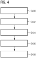
- Figure 4 is a flowchart of a method for positioning the sample 102 with the positioning device 200 according Figures 2 and 3 .
- the third circle element 206 is moved from an initial position to a second position. Thereby, the sample carrier 104 received in the fourth opening 218 of the third circle element 206 is also moved from the initial position to the second position. Both the initial position and the second position are located inside the diameter of the first circle element 202.
- step S404 the controller 118 determines relative rotations of the three circle elements 202, 204, 206 with respect to each other in order to position and orient the sample carrier 104 received in the fourth opening 218 according to the user input.
- Each position of the third circle element 206 is uniquely determined by a first relative rotation between the base element 208 and the first circle element 202, and a second relative rotation between the first circle element 202 and the second circle element 204.
- Each orientation of the third circle element 206 is uniquely determined by the first relative rotation, the second relative rotation, and a third relative rotation between the second circle element 204 and the third circle element 206. Accordingly, the controller 118 determines the first relative rotation, the second relative rotation, and the third relative rotation based on the user input.
- step S406 the circle elements 202, 204, 206 are moved by the drive units 220, 222, 224 according to the first relative rotation, the second relative rotation, and the third relative rotation.
- the position and the orientation of the third circle element 206 are uniquely determined by the first relative rotation, the second relative rotation, and the third relative rotation, there is no unique path between the initial position and the second position. Additional constraints may be placed on the path, for example that the third circle element 206 moves linearly or in a straight line.
- aspects described in the context of a method step also represent a description of a corresponding block or item or feature of a corresponding apparatus.
Landscapes
- Physics & Mathematics (AREA)
- Chemical & Material Sciences (AREA)
- Analytical Chemistry (AREA)
- General Physics & Mathematics (AREA)
- Optics & Photonics (AREA)
- Engineering & Computer Science (AREA)
- Multimedia (AREA)
- Microscoopes, Condenser (AREA)
- Wire Bonding (AREA)
- Die Bonding (AREA)
- Container, Conveyance, Adherence, Positioning, Of Wafer (AREA)
Abstract
Description
- The invention relates to a positioning device for an imaging device. The invention also relates to an imaging device, in particular a microscope. Further, the invention relates to a method for positioning a sample, and to a computer program product.
- Microscopes typically comprise a microscope stage configured to position a sample in the field of view of the microscopes optical system. Typical microscope stages comprise two or more rectangular plates arranged one above the other. A first plate is configured to be moved along the x-direction, and a second plate is configured to be moved along the y-direction. Thereby, the known microscope stage provides two degrees of freedom in which the sample can be moved. For this reason, microscope stages having two degrees of freedom are also called xy-tables. The plates are typically provided with a linear guide on two sides and may be moved by a motor. The plates may comprise an opening in which a sample carrier having the sample mounted upon is received, and through which the sample may be observed or illuminated.
- However, the known plate based microscope stages have a number disadvantages: The rectangular plates are not supported on at least two sides, and are therefore susceptible to vibration. Typically, there is a sizable gap between the plates. This arrangement is unfavorable for incubation applications, since the gap must be provided with a gastight seal before the arrangement can be used in an incubation application. Further, there is a risk of for example a sample carrier getting caught in the gap between the plates and being crushed. Since the plates are arranged atop of each other the arrangement of plates is also very thick. A microscope objective may therefore need to be moved deep into the opening in order to observe the sample. Thus, there is also a risk of the microscope objective colliding with the plates when the plates are moved. Lastly, the microscope stage cannot easily be integrated into a microscope housing, as space must be reserved in the periphery of the stage due to the extension of the plates.
- It is therefore an object to provide positioning device for an imaging device and a method for positioning a sample that overcome the aforementioned disadvantages of plate based microscope stages.
- The aforementioned object is achieved by the subject-matter of the independent claims. Advantageous embodiments are defined in the dependent claims and the following description.
- The proposed positioning device for an imaging device comprises a base element having a first opening, a first circle element arranged rotatably in the first opening, the first circle element having a second opening, a second circle element arranged rotatably in the second opening and having a third opening. The center of rotation of the second circle element is eccentric with respect to the center of rotation of the first circle element. The positioning device further comprises a third circle element arranged rotatably in the third opening. The center of rotation of the third circle element is eccentric with respect to the center of rotation of the second circle element, and wherein the third circle element comprises a fourth opening configured to receive a sample carrier.
- Due to the eccentricity of the center of rotation of the second circle element and the third circle element, the fourth opening can be move freely inside the first opening by simply rotating the first circle element and the second circle element. The orientation of the fourth opening can further be controlled by rotating the third circle element. Thus, a sample mounted on the sample carrier received in the fourth opening can be moved freely inside the first opening. The proposed positioning device therefore has three degrees of freedom. The sample can be moved in the x-direction and the y-direction and can additionally be rotated.
- The circle elements are nested within each other and are all arranged in one plane. Thus, compared to a positioning device comprising plates arranged atop of each other, the proposed positioning device is very flat. Because of this flatness, an objective of the imaging device can be moved very close to the sample located in the fourth opening without the risk of the microscope objective colliding with the positioning device. The circle elements are supported along their circumference by their respective supporting element. This results in a higher stiffness of the arrangement of circle elements, and thus better vibration characteristics since no vibration direction dominates. Further, since the circle elements are supported along their circumference there is no substantial gap between two adjacent elements. This significantly reduces the risk of an object, for example a sample carrier, a piece of cloth or a finger of a user, getting caught between two of the elements. This makes the positioning device safer to operate. Further, the gap between two adjacent elements can very easily be provided with a gastight seal, making the proposed positioning device suitable for incubation applications. The circle elements only move within the area of the first opening of the base element. The footprint of the positioning device is therefore entirely defined by the base element. No moving element will extend over the base element. This simple geometry makes it easy to integrate the positioning device into a housing of the imaging device. Thus, the proposed positioning device overcomes all of the abovementioned disadvantages of plate based positioning device.
- In a preferred embodiment, the positioning device comprises a controller configured to receive a user input, to determine based on the user input a second position of the fourth opening within the first opening, and to move the fourth opening from an initial position to the second position by rotating at least the first circle element, and the second circle element relative to each other. The user input defines the second position. At least the first circle element and the second circle element are then rotated in order to position the fourth opening, and thus the sample carrier and the sample at the second position. The rotation of the first circle element and the second circle element are controlled by the controller, thus the positioning device can be used to automatically move the sample carrier mounted in the fourth opening.
- In another preferred embodiment, the controller is configured to translate the user input into a rotation of at least the first circle element, and the second circle element. Each position of the fourth opening inside the first opening corresponds to a unique rotational position of the first circle element and the second circle element. In this embodiment, the controller is configured to translate the user input which may be in the form of a cartesian coordinate, i.e. x-y-position, into a rotation of the first and second circle elements. Thus, the user only needs to input an x-y-position in order to position the sample making the positioning device easy to use.
- In another preferred embodiment, the controller is configured to determine based on the user input a first relative rotation between the base element and the first circle element, and a second relative rotation between the first circle element and the second circle element. The controller is further configured to rotate the first circle element according to the first relative rotation, and the second circle element according to the second relative rotation in order to move the fourth opening to the second position. In this embodiment, the translation of the user input into the rotation of the first and second circle elements is realized by determining the first relative rotation and the second relative rotation. In particular, the controller may translate the user input which may be in the form of a cartesian coordinate into the first relative rotation and the second relative rotation which may be in the form of polar coordinates.
- In another preferred embodiment, the controller is configured to determine based on the user input a third relative rotation between the second circle element and the third circle element. The controller is further configured to rotate the third circle element according to the third relative rotation in order to move the fourth opening to the second position. The rotation of the third circle element orients the fourth opening, and thus the sample carrier received therein. In this embodiment, the user input comprises information about the desired orientation of the sample carrier. The controller is configured to translate the desired orientation into the third relative rotation. Since orientation of the fourth opening also depends on the rotational position of the first circle element and the second circle element, the controller preferably takes these into account when determining the third relative rotation. The positioning device according to this embodiment can be used to automatically orient the sample carrier mounted in the fourth opening, thereby automating all three degrees of freedom making the positioning device even more easy to use.
- In another preferred embodiment, the controller is configured to determine the third relative rotation such that the relative rotation of the third circle element with respect to the base element is the same in the initial position and the second position. Rotating the first circle element and the second circle element necessarily rotates the fourth opening, and thus the sample carrier received therein. In order to emulate the linear movement of a known plate based positioning device, the controller according to this embodiment preserves the orientation of the fourth opening. In particular, the controller may also be configured to facilitate a linear movement of the fourth opening between the initial position and the second position. Thereby, a user already familiar with known microscope stages can easily adapt to use the positioning device according to this embodiment.
- In another preferred embodiment, the positioning unit comprises a first drive unit configured to rotate the first circle element, a second drive unit configured to rotate the second circle element, and a third drive unit configured to rotate the third circle element. The drive unit may in particular be motor units or magnetic drives. The drive units are in particular controlled by the controller. In this embodiment, the movements of the circle elements are motorized by the drive units. Thereby, the positioning of the fourth opening, and thus the sample carrier is completely automated.
- In another preferred embodiment, the first drive unit is arranged on the base element, the second drive unit is arranged on the first circle element, and the third drive element is arranged on the second circle element. In this arrangement, the drive unit and the circle element moved by said drive unit are mounted on the same element. This configuration is mechanically very stable and facilitates a very low vibration movement of the circle elements.
- In another preferred embodiment, the first drive unit, the second drive unit, and the third drive unit each comprise a stepper motor. Alternatively, the first drive unit, the second drive unit, and the third drive unit each comprise a linear motor. Linear motors and stepper motors can be used to precisely control a movement. In this embodiment it is therefore possible to control the rotation of the circle elements, and thus the position of the fourth opening very precisely.
- In another preferred embodiment, the positioning device comprises a first position determination unit configured to determine the position of the first circle element relative to the base element, a second position determination unit configured to determine the position of the second circle element relative to the first circle, and a third position determination unit configured to determine the position of the third circle element relative to the second circle element. The relative position, i.e. their angle towards each other, of the circle element to each other uniquely determines the position and orientation of the fourth opening. The position determination units may therefore be used to precisely determine the position and orientation of the fourth opening, and thus the sample carrier received therein. This information can be used by the control unit to control the positioning device with even greater precision.
- In another preferred embodiment, the first opening, the second opening, and the third opening are circular; wherein the second opening is eccentric with respect to the first circle element; and wherein the third opening is eccentric with respect to the second circle element. In this embodiment the circle elements are supported over their entire circumference by their respective supporting element. This provides an even greater stiffness of the arrangement of circle elements and therefore an even smoother rotation.
- In another preferred embodiment, the fourth opening is rectangular. A rectangular opening can easily receive most sample carriers, in particular microscope slides and microwell plates. Thus, the present embodiment is compatible with most sample carriers.
- In another preferred embodiment, the first circle element, the second circle element, and the third circle element are mounted by rolling bearings. Rolling bearings create very little vibration when the circle element rotate. Thus, the rolling bearings allow the circle element to run very smoothly.
- The inventions also relates to an imaging device comprising the positioning device described above. Preferably, the imaging device is a microscope, in particular an inverse microscope. The imaging device has the same advantages as the positioning device described above.
- The invention also relates to a method for positioning a sample with a positioning device described above. The method comprises the following steps: Arranging a sample carrier carrying the sample in the fourth opening. Determining based on a user input a second position of the fourth opening within the first opening. Moving the fourth opening from an initial position to the second position by rotating at least the first circle element, and the second circle element relative to each other.
- The method has the same advantages as the positioning device described above and can be supplemented using the features of the dependent claims directed at the positioning device.
- The invention further relates to a computer program product comprising a program code configured to perform the method described above, when the computer program product is run on a processor.
- The computer program product has the same advantages as the positioning device and the method described above, and can in particular be supplemented using the features of the dependent claims directed at the positioning device.
- Hereinafter, specific embodiments are described referring to the drawings, wherein:
- Figure 1
- is a schematic view of an imaging device according to an embodiment;
- Figure 2
- is a schematic top view of a positioning device of the imaging device according to
Figure 1 ; - Figure 3
- is a schematic sectional view of the positioning device according to
Figure 2 ; and - Figure 4
- is a flowchart of a method for positioning a sample with the positioning device according
Figures 2 and3 . -
Figure 1 is a schematic view of animaging device 100 according to an embodiment. - In the present embodiment, the
imaging device 100 is exemplary formed as an inverse microscope. However, theimaging device 100 may also be any other type of microscope, e.g. an upright microscope or a box type microscope. In particular, theimaging device 100 is not limited to be a microscope. Theimaging device 100 may for example be a device for inspecting semiconductor work pieces. - The
imaging device 100 is configured to image asample 102 arranged on asample carrier 104, for example a microscope slide, a microwell plate or a petri dish. For capturing an image of thesample 102, theimaging device 100 comprises anoptical imaging system 106. Theoptical imaging system 106 comprises an objective 108 directed at thesample 102 from below, and adetector element 110. The objective 108 receives detection light emitted by thesample 102 and directs the received detection light towards thedetector element 110. Anillumination unit 112 configured to illuminate thesample 102 is exemplary arranged above thesample 102. Thus, theimaging device 100 according to the present embodiment is configured for transmitted light microscopy. Thesample carrier 104 and thesample 102 are arranged on apositioning device 114 configured to position thesample 102 in the field of view of the objective 108. Thepositioning device 114 is described below in more detail with reference toFigures 2 and3 . - The
imaging device 100 further comprises acontrol unit 116. Thecontrol unit 116 is connected to theoptical imaging device 100, theillumination unit 112, and thepositioning device 114, and configured to control theimaging device 100. In particular, thecontrol unit 116 comprises acontroller 118 configured to control thepositioning device 114. Thecontroller 118 of thepositioning device 114 is configured to perform a method for positioning thesample 102 that is described below with reference toFigure 4 . -
Figure 2 is a schematic top view of thepositioning device 200 of theimaging device 100 according toFigure 1 . - Contrary to known plate based positioning devices which position the
sample carrier 104 by a linear movement of plates, thepositioning device 200 shown inFigure 2 positions thesample carrier 104 by a rotational movement of threecircle elements circle elements third circle element 206, which is the smallest of the three nestedcircle elements first circle element 202, which is the biggest of the three nestedcircle elements sample carrier 104 which is arranged on thethird circle element 206, may also be positioned freely within the diameter of thefirst circle element 202. - The
positioning device 200 comprises abase element 208 exemplary shown to have a square footprint. Thebase element 208 may be fixed to theimaging device 100 by means of bolt holes 210. Fixing thepositioning device 200 prevents thepositioning device 200 from moving relative to theimaging device 100. Afirst opening 212 of thebase element 208 is circular and has a diameter that is slightly smaller than the length of an edge of thebase element 208. - The three
circle elements first opening 212 of thebase element 208. The diameter of thefirst circle element 202 is chosen such that thefirst circle element 202 fits thefirst opening 212. Thus, thefirst circle element 202 is mounted along its entire circumference by thebase element 208. Thefirst circle element 202 can rotate freely within thefirst opening 212, and its axis of rotation is perpendicular to the image plane ofFigure 2 . Thefirst circle element 202 has asecond opening 214 that is circular and arranged eccentrically with respect to thefirst circle element 202. The diameter of thesecond opening 214 is about three quarters of the diameter of thefirst circle element 202. - A
second circle element 204 is received in thesecond opening 214. The diameter of thesecond circle element 204 is smaller than thefirst circle element 202, and chosen such that thesecond circle element 204 fits thesecond opening 214. Thus, thesecond circle element 204 is mounted along its entire circumference by thefirst circle element 202. Thesecond circle element 204 can rotate freely within thesecond opening 214, and its axis of rotation is also perpendicular to the image plane ofFigure 2 . The axis of rotation of thesecond circle element 204 is eccentric with respect to thefirst circle element 202. Thesecond circle element 204 has athird opening 216 that is circular and arranged eccentrically with respect to thesecond circle element 204. The diameter of thethird opening 216 is about three quarters of the diameter of thesecond circle element 204 or about half of the diameter of thefirst circle element 202. - The
third circle element 206 is received in thethird opening 216. The diameter of thethird circle element 206 is smaller than thesecond circle element 204, and chosen such that thethird circle element 206 fits thethird opening 216. Accordingly, thethird circle element 206 is mounted along its entire circumference by thesecond circle element 204. Thethird circle element 206 can rotate freely within thethird opening 216, and its axis of rotation is also perpendicular to the image plane ofFigure 2 . The axis of rotation of thethird circle element 206 is eccentric with respect to thesecond circle element 204. Thethird circle element 206 has afourth opening 218 that is rectangular and configured to receive thesample carrier 104. Thefourth opening 218 goes from top to bottom through theentire positioning device 200, and thereby allows thesample 102 mounted on thesample carrier 104 to be observed from below. - In order to automatically rotate the three
circle elements drive units first drive unit 220 is arranged on thebase element 208 and configured to rotate thefirst circle element 202. Asecond drive unit 222 is arranged on thefirst circle element 202 and configured to rotate thesecond circle element 204. Athird drive unit 224 is arranged on thesecond circle element 204 and configured to rotate thethird circle element 206. According to the present embodiment, each of thecircle elements drive unit same element respective circle element circle elements respective circle element drive units base element 208. - The
positioning device 200 is described in more detail below with reference toFigure 3 which shows a sectional view of thepositioning device 200. A dashed line A inFigure 2 indicates the sectional axis of the sectional view ofFigure 3 . -
Figure 3 is a schematic sectional view of thepositioning device 200 according toFigure 2 . - As can be seen in
Figure 3 , the nestedcircle elements positioning device 200 according toFigures 2 and3 a flat profile when viewed from the side. Due to the flatness of thepositioning device 200, theobjective 108 of theimaging device 100 can be moved very close to thesample 102 arranged on thesample carrier 104 when it is received in a top portion of thefourth opening 218, without actually moving into thefourth opening 218. This greatly reduces the risk of the objective 108 colliding with thepositioning device 200. - As can also be seen in
Figure 3 , there is no sizeable gap between two neighboringcircle elements first circle element 202 and thebase element 208. Further, the small gaps are covered each from the top by alid portion respective circle element lid portions -
Figure 3 exemplary shows a sectional view of asecond drive unit 222 mounted on thefirst circle element 202 configured to rotate thesecond circle element 204. Thedrive units circle elements drive units motor 306 driving acogwheel 308 that engages with a pinion of one of thelid portions cogwheel 308 moves therespective lid portion circle elements element Figure 3 are possible. For example, one of more of thedrive units circle elements - The
circle elements bearings bearings circle elements circle elements bearings circle elements bearings 312 mounting thesecond circle element 204 and the rollingbearings 314 mounting thethird circle element 206 are arranged in the same plane as therespective circle elements bearings 310 mounting thefirst circle element 202 are arranged below thefirst circle element 202. This arrangement allows the diameter of thefirst circle element 202 to be as big as possible compared to the footprint of thebase element 208. Making the diameter of thefirst circle element 202 large is important since the diameter of thefirst circle element 202 determines the area in which thesample carrier 104 can be moved. -
Figure 4 is a flowchart of a method for positioning thesample 102 with thepositioning device 200 accordingFigures 2 and3 . - During the process the method defines, the
third circle element 206 is moved from an initial position to a second position. Thereby, thesample carrier 104 received in thefourth opening 218 of thethird circle element 206 is also moved from the initial position to the second position. Both the initial position and the second position are located inside the diameter of thefirst circle element 202. - The process is started in step S400. In step S402 the
controller 118 of thepositioning device 200 receives a user input, for example via a user input device such as a keyboard and/or mouse. The user input comprises at least a position information and may comprise an orientation information. The position information may be an absolute position, i.e. a position with respect to thepositioning device 200, or a relative position, i.e. a position with respect to the current position. An absolute position may be denoted by a set of cartesian coordinates. A relative position may be denoted in the form of a vector. The orientation information may either comprise an absolute orientation, i.e. a rotation with respect to thepositioning device 200, or a relative orientation, i.e. a rotation with respect to the current rotation. In particular, the orientation information may comprise that the absolute orientation must be the same in the initial position and the second position and/or that the orientation must not change during the movement between the initial position and the second position. - In step S404 the
controller 118 determines relative rotations of the threecircle elements sample carrier 104 received in thefourth opening 218 according to the user input. - Each position of the
third circle element 206 is uniquely determined by a first relative rotation between thebase element 208 and thefirst circle element 202, and a second relative rotation between thefirst circle element 202 and thesecond circle element 204. Each orientation of thethird circle element 206 is uniquely determined by the first relative rotation, the second relative rotation, and a third relative rotation between thesecond circle element 204 and thethird circle element 206. Accordingly, thecontroller 118 determines the first relative rotation, the second relative rotation, and the third relative rotation based on the user input. - In step S406 the
circle elements drive units third circle element 206 are uniquely determined by the first relative rotation, the second relative rotation, and the third relative rotation, there is no unique path between the initial position and the second position. Additional constraints may be placed on the path, for example that thethird circle element 206 moves linearly or in a straight line. After thethird circle element 206 has reached the second position, the process is stopped in step S408. - Identical or similarly acting elements are designated with the same reference signs in all Figures. As used herein the term "and/or" includes any and all combinations of one or more of the associated listed items and may be abbreviated as "/". Individual features of the embodiments and all combinations of individual features of the embodiments among each other as well as in combination with individual features or feature groups of the preceding description and/or claims are considered disclosed.
- Although some aspects have been described in the context of an apparatus, it is clear that these aspects also represent a description of the corresponding method, where a block or device corresponds to a method step or a feature of a method step.
- Analogously, aspects described in the context of a method step also represent a description of a corresponding block or item or feature of a corresponding apparatus.
-
- 100
- imaging device
- 102
- sample
- 104
- sample carrier
- 106
- optical imaging system
- 108
- objective
- 110
- detector element
- 112
- illumination unit
- 114
- positioning device
- 116
- control unit
- 118
- controller
- 200
- positioning device
- 202, 204, 206
- circle element
- 208
- base element
- 210
- bolt hole
- 212, 214, 216, 218
- opening
- 220, 222, 224
- drive unit
- 300, 302, 304
- lid portion
- 306
- motor
- 308
- cogwheel
- 310, 312, 314
- rolling bearings
- A, B
- lines
Claims (15)
- A positioning device (114, 200) for an imaging device (100), comprisinga base element (208) having a first opening (212),a first circle element (202) arranged rotatably in the first opening (212), the first circle element (202) having a second opening (214),a second circle element (204) arranged rotatably in the second opening (214) and having a third opening (216), wherein the center of rotation of the second circle element (204) is eccentric with respect to the center of rotation of the first circle element (202), anda third circle element (206) arranged rotatably in the third opening (216), wherein the center of rotation of the third circle element (206) is eccentric with respect to the center of rotation of the second circle element (204), and wherein the third circle element (206) comprises a fourth opening (218) configured to receive a sample carrier (104).
- The positioning device (114, 200) according to claim 1, comprising a controller (118) configured to receive a user input, to determine based on the user input a second position of the fourth opening (218) within the first opening (212), and to move the fourth opening (218) from an initial position to the second position by rotating at least the first circle element (202), and the second circle element (204) relative to each other.
- The positioning device (114, 200) according to claim 2, wherein the controller (118) is configured to translate the user input into a rotation of at least the first circle element (202), and the second circle element (204).
- The positioning device (114, 200) according to claim 2 or 3, wherein the controller (118) is configured to determine based on the user input a first relative rotation between the base element (208) and the first circle element (202), and a second relative rotation between the first circle element (202) and the second circle element (204); and wherein the controller (118) is configured to rotate the first circle element (202) according to the first relative rotation, and the second circle element (204) according to the second relative rotation in order to move the fourth opening (218) to the second position.
- The positioning device (114, 200) according to claim 4, wherein the controller (118) is configured to determine based on the user input a third relative rotation between the second circle element (204) and the third circle element (206); and wherein the controller (118) is configured to rotate the third circle element (206) according to the third relative rotation in order to move the fourth opening (218) to the second position.
- The positioning device (114, 200) according to claim 5, wherein the controller (118) is configured to determine the third relative rotation such that the relative rotation of the third circle element (206) with respect to the base element (208) is the same in the initial position and the second position.
- The positioning device (114, 200) according to any of the preceding claims, comprising a first drive unit (220) configured to rotate the first circle element (202), a second drive unit (222) configured to rotate the second circle element (204), and a third drive unit (224) configured to rotate the third circle element (206).
- The positioning device (114, 200) according to claim 7, wherein the first drive unit (220) is arranged on the base element (208), the second drive unit (222) is arranged on the first circle element (202), and the third drive element is arranged on the second circle element (204).
- The positioning device (114, 200) according to claim 7 or 8, wherein the first drive unit (220), the second drive unit (222), and the third drive unit (224) each comprise a stepper motor.
- The positioning device (114, 200) according to claim 7 or 8, wherein the first drive unit (220), the second drive unit (222), and the third drive unit (224) each comprise a linear motor.
- The positioning device (114, 200) according to any one of the preceding claims, comprising a first position determination unit configured to determine the position of the first circle element (202) relative to the base element (208), a second position determination unit configured to determine the position of the second circle element (204) relative to the first circle, and a third position determination unit configured to determine the position of the third circle element (206) relative to the second circle element (204).
- The positioning device (114, 200) according to any one of the preceding claims, wherein the first opening (212), the second opening (214), and the third opening (216) are circular; wherein the second opening (214) is eccentric with respect to the first circle element (202); and wherein the third opening (216) is eccentric with respect to the second circle element (204).
- An imaging device (100) comprising a positioning device (114, 200) according to any one of the preceding claims.
- Method for positioning a sample (102) with a positioning device (114, 200) according to any one of the claims 1 to 13, the method comprisingarranging a sample carrier (104) carrying the sample (102) in the fourth opening (218);determining based on a user input a second position of the fourth opening (218) within the first opening (212);moving the fourth opening (218) from an initial position to the second position by rotating at least the first circle element (202), and the second circle element (204) relative to each other.
- Computer program product comprising a program code configured to perform the method according to claim 14, when the computer program product is run on a processor.
Priority Applications (5)
| Application Number | Priority Date | Filing Date | Title |
|---|---|---|---|
| EP25219630.8A EP4679159A3 (en) | 2022-05-18 | 2022-05-18 | Positioning device for an imaging device and method |
| EP22174057.4A EP4279976B1 (en) | 2022-05-18 | 2022-05-18 | Positioning device for an imaging device and method |
| US18/864,921 US12320967B2 (en) | 2022-05-18 | 2023-03-21 | Positioning device for an imaging device and method |
| PCT/EP2023/057135 WO2023222283A1 (en) | 2022-05-18 | 2023-03-21 | Positioning device for an imaging device and method |
| CN202380039936.2A CN119173799A (en) | 2022-05-18 | 2023-03-21 | Positioning device and method for imaging device |
Applications Claiming Priority (1)
| Application Number | Priority Date | Filing Date | Title |
|---|---|---|---|
| EP22174057.4A EP4279976B1 (en) | 2022-05-18 | 2022-05-18 | Positioning device for an imaging device and method |
Related Child Applications (1)
| Application Number | Title | Priority Date | Filing Date |
|---|---|---|---|
| EP25219630.8A Division EP4679159A3 (en) | 2022-05-18 | 2022-05-18 | Positioning device for an imaging device and method |
Publications (3)
| Publication Number | Publication Date |
|---|---|
| EP4279976A1 true EP4279976A1 (en) | 2023-11-22 |
| EP4279976C0 EP4279976C0 (en) | 2025-12-03 |
| EP4279976B1 EP4279976B1 (en) | 2025-12-03 |
Family
ID=81748538
Family Applications (2)
| Application Number | Title | Priority Date | Filing Date |
|---|---|---|---|
| EP22174057.4A Active EP4279976B1 (en) | 2022-05-18 | 2022-05-18 | Positioning device for an imaging device and method |
| EP25219630.8A Pending EP4679159A3 (en) | 2022-05-18 | 2022-05-18 | Positioning device for an imaging device and method |
Family Applications After (1)
| Application Number | Title | Priority Date | Filing Date |
|---|---|---|---|
| EP25219630.8A Pending EP4679159A3 (en) | 2022-05-18 | 2022-05-18 | Positioning device for an imaging device and method |
Country Status (4)
| Country | Link |
|---|---|
| US (1) | US12320967B2 (en) |
| EP (2) | EP4279976B1 (en) |
| CN (1) | CN119173799A (en) |
| WO (1) | WO2023222283A1 (en) |
Citations (2)
| Publication number | Priority date | Publication date | Assignee | Title |
|---|---|---|---|---|
| US20110089771A1 (en) * | 2009-10-16 | 2011-04-21 | Thorlabs, Inc. | Motorized stage |
| CN210427932U (en) * | 2019-08-29 | 2020-04-28 | 黔西南布依族苗族自治州人民医院 | Microscope objective table capable of adjusting horizontal position |
Family Cites Families (2)
| Publication number | Priority date | Publication date | Assignee | Title |
|---|---|---|---|---|
| JP2011100629A (en) * | 2009-11-06 | 2011-05-19 | Sumitomo Electric Ind Ltd | Sample table for microscope, and inspection method for linear element |
| DE102012016830B4 (en) * | 2012-08-24 | 2021-08-26 | Bruker Daltonics GmbH & Co. KG | Preparation device for mass spectrometric samples |
-
2022
- 2022-05-18 EP EP22174057.4A patent/EP4279976B1/en active Active
- 2022-05-18 EP EP25219630.8A patent/EP4679159A3/en active Pending
-
2023
- 2023-03-21 CN CN202380039936.2A patent/CN119173799A/en active Pending
- 2023-03-21 US US18/864,921 patent/US12320967B2/en active Active
- 2023-03-21 WO PCT/EP2023/057135 patent/WO2023222283A1/en not_active Ceased
Patent Citations (2)
| Publication number | Priority date | Publication date | Assignee | Title |
|---|---|---|---|---|
| US20110089771A1 (en) * | 2009-10-16 | 2011-04-21 | Thorlabs, Inc. | Motorized stage |
| CN210427932U (en) * | 2019-08-29 | 2020-04-28 | 黔西南布依族苗族自治州人民医院 | Microscope objective table capable of adjusting horizontal position |
Also Published As
| Publication number | Publication date |
|---|---|
| US12320967B2 (en) | 2025-06-03 |
| US20250110323A1 (en) | 2025-04-03 |
| CN119173799A (en) | 2024-12-20 |
| EP4279976C0 (en) | 2025-12-03 |
| EP4279976B1 (en) | 2025-12-03 |
| EP4679159A2 (en) | 2026-01-14 |
| EP4679159A3 (en) | 2026-03-25 |
| WO2023222283A1 (en) | 2023-11-23 |
Similar Documents
| Publication | Publication Date | Title |
|---|---|---|
| CA2844994C (en) | Imaging systems, cassettes, and methods of using the same | |
| US4627009A (en) | Microscope stage assembly and control system | |
| US7553334B2 (en) | Defective product inspection apparatus, probe positioning method and probe moving method | |
| CN113607755A (en) | Automatic detection device for wafer | |
| EP1865354A1 (en) | Microscopic image capturing device | |
| KR20010029736A (en) | Stage for charged particle microscopy system | |
| CN112840351A (en) | Macro inspection system, instrument and method | |
| CA2842721A1 (en) | Imaging system and techniques | |
| EP4679159A2 (en) | Positioning device for an imaging device and method | |
| CN111279200B (en) | Slide rack carousel | |
| KR0141161B1 (en) | Stage device with rotary table and driving method of stage device | |
| US20180231759A1 (en) | Microscope having an objective-exchanging device | |
| US20060033056A1 (en) | Dynamic focusing method and apparatus | |
| JP4826584B2 (en) | Translational and two-degree-of-freedom stage device and three-degree-of-freedom stage device using the same | |
| US20050237520A1 (en) | Apparatus for handling of a disklike member, especially for handling of a wafer | |
| IES20040529A2 (en) | An inspection system support mechanism | |
| US10191269B2 (en) | Slide holder for an optical microscope | |
| US6463664B1 (en) | Multi-axis planar slide system | |
| AU2015201450B2 (en) | Imaging systems, cassettes, and methods of using the same | |
| CN119334943B (en) | Full-automatic double-reflection microscopic detection observation device and method | |
| EP4614207A1 (en) | Sample positioning device and light sheet microscope | |
| CN224152750U (en) | Imaging modules and microscopic imaging equipment | |
| CN117215046B (en) | A large-range, multi-angle optical imaging system with an ultra-large imaging space | |
| CN219391840U (en) | Detection equipment | |
| EP4621833A1 (en) | Improved positioning device and method |
Legal Events
| Date | Code | Title | Description |
|---|---|---|---|
| PUAI | Public reference made under article 153(3) epc to a published international application that has entered the european phase |
Free format text: ORIGINAL CODE: 0009012 |
|
| STAA | Information on the status of an ep patent application or granted ep patent |
Free format text: STATUS: THE APPLICATION HAS BEEN PUBLISHED |
|
| AK | Designated contracting states |
Kind code of ref document: A1 Designated state(s): AL AT BE BG CH CY CZ DE DK EE ES FI FR GB GR HR HU IE IS IT LI LT LU LV MC MK MT NL NO PL PT RO RS SE SI SK SM TR |
|
| P01 | Opt-out of the competence of the unified patent court (upc) registered |
Effective date: 20231221 |
|
| STAA | Information on the status of an ep patent application or granted ep patent |
Free format text: STATUS: REQUEST FOR EXAMINATION WAS MADE |
|
| 17P | Request for examination filed |
Effective date: 20240521 |
|
| RBV | Designated contracting states (corrected) |
Designated state(s): AL AT BE BG CH CY CZ DE DK EE ES FI FR GB GR HR HU IE IS IT LI LT LU LV MC MK MT NL NO PL PT RO RS SE SI SK SM TR |
|
| GRAP | Despatch of communication of intention to grant a patent |
Free format text: ORIGINAL CODE: EPIDOSNIGR1 |
|
| STAA | Information on the status of an ep patent application or granted ep patent |
Free format text: STATUS: GRANT OF PATENT IS INTENDED |
|
| INTG | Intention to grant announced |
Effective date: 20250813 |
|
| GRAS | Grant fee paid |
Free format text: ORIGINAL CODE: EPIDOSNIGR3 |
|
| GRAA | (expected) grant |
Free format text: ORIGINAL CODE: 0009210 |
|
| STAA | Information on the status of an ep patent application or granted ep patent |
Free format text: STATUS: THE PATENT HAS BEEN GRANTED |
|
| AK | Designated contracting states |
Kind code of ref document: B1 Designated state(s): AL AT BE BG CH CY CZ DE DK EE ES FI FR GB GR HR HU IE IS IT LI LT LU LV MC MK MT NL NO PL PT RO RS SE SI SK SM TR |
|
| REG | Reference to a national code |
Ref country code: CH Ref legal event code: F10 Free format text: ST27 STATUS EVENT CODE: U-0-0-F10-F00 (AS PROVIDED BY THE NATIONAL OFFICE) Effective date: 20251203 Ref country code: GB Ref legal event code: FG4D |
|
| REG | Reference to a national code |
Ref country code: DE Ref legal event code: R096 Ref document number: 602022025968 Country of ref document: DE |
|
| REG | Reference to a national code |
Ref country code: IE Ref legal event code: FG4D |
|
| P04 | Withdrawal of opt-out of the competence of the unified patent court (upc) registered |
Free format text: CASE NUMBER: APP_596718_1/2023 Effective date: 20251217 |
|
| U01 | Request for unitary effect filed |
Effective date: 20251212 |
|
| U07 | Unitary effect registered |
Designated state(s): AT BE BG DE DK EE FI FR IT LT LU LV MT NL PT RO SE SI Effective date: 20251217 |
|
| PGFP | Annual fee paid to national office [announced via postgrant information from national office to epo] |
Ref country code: GB Payment date: 20260304 Year of fee payment: 5 |
|
| PG25 | Lapsed in a contracting state [announced via postgrant information from national office to epo] |
Ref country code: ES Free format text: LAPSE BECAUSE OF FAILURE TO SUBMIT A TRANSLATION OF THE DESCRIPTION OR TO PAY THE FEE WITHIN THE PRESCRIBED TIME-LIMIT Effective date: 20251203 |
|
| PG25 | Lapsed in a contracting state [announced via postgrant information from national office to epo] |
Ref country code: NO Free format text: LAPSE BECAUSE OF FAILURE TO SUBMIT A TRANSLATION OF THE DESCRIPTION OR TO PAY THE FEE WITHIN THE PRESCRIBED TIME-LIMIT Effective date: 20260303 |
|
| PG25 | Lapsed in a contracting state [announced via postgrant information from national office to epo] |
Ref country code: HR Free format text: LAPSE BECAUSE OF FAILURE TO SUBMIT A TRANSLATION OF THE DESCRIPTION OR TO PAY THE FEE WITHIN THE PRESCRIBED TIME-LIMIT Effective date: 20251203 |
|
| PG25 | Lapsed in a contracting state [announced via postgrant information from national office to epo] |
Ref country code: RS Free format text: LAPSE BECAUSE OF FAILURE TO SUBMIT A TRANSLATION OF THE DESCRIPTION OR TO PAY THE FEE WITHIN THE PRESCRIBED TIME-LIMIT Effective date: 20260303 |
|
| PG25 | Lapsed in a contracting state [announced via postgrant information from national office to epo] |
Ref country code: PL Free format text: LAPSE BECAUSE OF FAILURE TO SUBMIT A TRANSLATION OF THE DESCRIPTION OR TO PAY THE FEE WITHIN THE PRESCRIBED TIME-LIMIT Effective date: 20251203 |