EP4279872B1 - Codeur magnétique incrémental - Google Patents
Codeur magnétique incrémental Download PDFInfo
- Publication number
- EP4279872B1 EP4279872B1 EP23173539.0A EP23173539A EP4279872B1 EP 4279872 B1 EP4279872 B1 EP 4279872B1 EP 23173539 A EP23173539 A EP 23173539A EP 4279872 B1 EP4279872 B1 EP 4279872B1
- Authority
- EP
- European Patent Office
- Prior art keywords
- encoder
- notching
- ring
- magnetic
- encoding
- Prior art date
- Legal status (The legal status is an assumption and is not a legal conclusion. Google has not performed a legal analysis and makes no representation as to the accuracy of the status listed.)
- Active
Links
Images






Classifications
-
- G—PHYSICS
- G01—MEASURING; TESTING
- G01D—MEASURING NOT SPECIALLY ADAPTED FOR A SPECIFIC VARIABLE; ARRANGEMENTS FOR MEASURING TWO OR MORE VARIABLES NOT COVERED IN A SINGLE OTHER SUBCLASS; TARIFF METERING APPARATUS; MEASURING OR TESTING NOT OTHERWISE PROVIDED FOR
- G01D5/00—Mechanical means for transferring the output of a sensing member; Means for converting the output of a sensing member to another variable where the form or nature of the sensing member does not constrain the means for converting; Transducers not specially adapted for a specific variable
- G01D5/12—Mechanical means for transferring the output of a sensing member; Means for converting the output of a sensing member to another variable where the form or nature of the sensing member does not constrain the means for converting; Transducers not specially adapted for a specific variable using electric or magnetic means
- G01D5/14—Mechanical means for transferring the output of a sensing member; Means for converting the output of a sensing member to another variable where the form or nature of the sensing member does not constrain the means for converting; Transducers not specially adapted for a specific variable using electric or magnetic means influencing the magnitude of a current or voltage
- G01D5/142—Mechanical means for transferring the output of a sensing member; Means for converting the output of a sensing member to another variable where the form or nature of the sensing member does not constrain the means for converting; Transducers not specially adapted for a specific variable using electric or magnetic means influencing the magnitude of a current or voltage using Hall-effect devices
- G01D5/145—Mechanical means for transferring the output of a sensing member; Means for converting the output of a sensing member to another variable where the form or nature of the sensing member does not constrain the means for converting; Transducers not specially adapted for a specific variable using electric or magnetic means influencing the magnitude of a current or voltage using Hall-effect devices influenced by the relative movement between the Hall device and magnetic fields
-
- G—PHYSICS
- G01—MEASURING; TESTING
- G01D—MEASURING NOT SPECIALLY ADAPTED FOR A SPECIFIC VARIABLE; ARRANGEMENTS FOR MEASURING TWO OR MORE VARIABLES NOT COVERED IN A SINGLE OTHER SUBCLASS; TARIFF METERING APPARATUS; MEASURING OR TESTING NOT OTHERWISE PROVIDED FOR
- G01D5/00—Mechanical means for transferring the output of a sensing member; Means for converting the output of a sensing member to another variable where the form or nature of the sensing member does not constrain the means for converting; Transducers not specially adapted for a specific variable
- G01D5/12—Mechanical means for transferring the output of a sensing member; Means for converting the output of a sensing member to another variable where the form or nature of the sensing member does not constrain the means for converting; Transducers not specially adapted for a specific variable using electric or magnetic means
- G01D5/14—Mechanical means for transferring the output of a sensing member; Means for converting the output of a sensing member to another variable where the form or nature of the sensing member does not constrain the means for converting; Transducers not specially adapted for a specific variable using electric or magnetic means influencing the magnitude of a current or voltage
-
- G—PHYSICS
- G01—MEASURING; TESTING
- G01D—MEASURING NOT SPECIALLY ADAPTED FOR A SPECIFIC VARIABLE; ARRANGEMENTS FOR MEASURING TWO OR MORE VARIABLES NOT COVERED IN A SINGLE OTHER SUBCLASS; TARIFF METERING APPARATUS; MEASURING OR TESTING NOT OTHERWISE PROVIDED FOR
- G01D5/00—Mechanical means for transferring the output of a sensing member; Means for converting the output of a sensing member to another variable where the form or nature of the sensing member does not constrain the means for converting; Transducers not specially adapted for a specific variable
- G01D5/12—Mechanical means for transferring the output of a sensing member; Means for converting the output of a sensing member to another variable where the form or nature of the sensing member does not constrain the means for converting; Transducers not specially adapted for a specific variable using electric or magnetic means
- G01D5/244—Mechanical means for transferring the output of a sensing member; Means for converting the output of a sensing member to another variable where the form or nature of the sensing member does not constrain the means for converting; Transducers not specially adapted for a specific variable using electric or magnetic means influencing characteristics of pulses or pulse trains; generating pulses or pulse trains
- G01D5/245—Mechanical means for transferring the output of a sensing member; Means for converting the output of a sensing member to another variable where the form or nature of the sensing member does not constrain the means for converting; Transducers not specially adapted for a specific variable using electric or magnetic means influencing characteristics of pulses or pulse trains; generating pulses or pulse trains using a variable number of pulses in a train
- G01D5/2451—Incremental encoders
-
- G—PHYSICS
- G05—CONTROLLING; REGULATING
- G05G—CONTROL DEVICES OR SYSTEMS INSOFAR AS CHARACTERISED BY MECHANICAL FEATURES ONLY
- G05G5/00—Means for preventing, limiting or returning the movements of parts of a control mechanism, e.g. locking controlling member
- G05G5/03—Means for enhancing the operator's awareness of arrival of the controlling member at a command or datum position; Providing feel, e.g. means for creating a counterforce
-
- G—PHYSICS
- G06—COMPUTING OR CALCULATING; COUNTING
- G06F—ELECTRIC DIGITAL DATA PROCESSING
- G06F3/00—Input arrangements for transferring data to be processed into a form capable of being handled by the computer; Output arrangements for transferring data from processing unit to output unit, e.g. interface arrangements
- G06F3/01—Input arrangements or combined input and output arrangements for interaction between user and computer
- G06F3/016—Input arrangements with force or tactile feedback as computer generated output to the user
-
- G—PHYSICS
- G06—COMPUTING OR CALCULATING; COUNTING
- G06F—ELECTRIC DIGITAL DATA PROCESSING
- G06F3/00—Input arrangements for transferring data to be processed into a form capable of being handled by the computer; Output arrangements for transferring data from processing unit to output unit, e.g. interface arrangements
- G06F3/01—Input arrangements or combined input and output arrangements for interaction between user and computer
- G06F3/03—Arrangements for converting the position or the displacement of a member into a coded form
- G06F3/033—Pointing devices displaced or positioned by the user, e.g. mice, trackballs, pens or joysticks; Accessories therefor
- G06F3/0362—Pointing devices displaced or positioned by the user, e.g. mice, trackballs, pens or joysticks; Accessories therefor with detection of one-dimensional [1D] translations or rotations of an operating part of the device, e.g. scroll wheels, sliders, knobs, rollers or belts
-
- G—PHYSICS
- G01—MEASURING; TESTING
- G01D—MEASURING NOT SPECIALLY ADAPTED FOR A SPECIFIC VARIABLE; ARRANGEMENTS FOR MEASURING TWO OR MORE VARIABLES NOT COVERED IN A SINGLE OTHER SUBCLASS; TARIFF METERING APPARATUS; MEASURING OR TESTING NOT OTHERWISE PROVIDED FOR
- G01D2205/00—Indexing scheme relating to details of means for transferring or converting the output of a sensing member
- G01D2205/90—Two-dimensional encoders, i.e. having one or two codes extending in two directions
-
- G—PHYSICS
- G01—MEASURING; TESTING
- G01D—MEASURING NOT SPECIALLY ADAPTED FOR A SPECIFIC VARIABLE; ARRANGEMENTS FOR MEASURING TWO OR MORE VARIABLES NOT COVERED IN A SINGLE OTHER SUBCLASS; TARIFF METERING APPARATUS; MEASURING OR TESTING NOT OTHERWISE PROVIDED FOR
- G01D7/00—Indicating measured values
- G01D7/007—Indication of measured value by tactile means
-
- G—PHYSICS
- G05—CONTROLLING; REGULATING
- G05G—CONTROL DEVICES OR SYSTEMS INSOFAR AS CHARACTERISED BY MECHANICAL FEATURES ONLY
- G05G1/00—Controlling members, e.g. knobs or handles; Assemblies or arrangements thereof; Indicating position of controlling members
- G05G1/08—Controlling members for hand actuation by rotary movement, e.g. hand wheels
- G05G1/10—Details, e.g. of discs, knobs, wheels or handles
-
- G—PHYSICS
- G05—CONTROLLING; REGULATING
- G05G—CONTROL DEVICES OR SYSTEMS INSOFAR AS CHARACTERISED BY MECHANICAL FEATURES ONLY
- G05G5/00—Means for preventing, limiting or returning the movements of parts of a control mechanism, e.g. locking controlling member
- G05G5/06—Means for preventing, limiting or returning the movements of parts of a control mechanism, e.g. locking controlling member for holding members in one or a limited number of definite positions only
Definitions
- the present invention relates to an incremental magnetic encoder.
- the present invention relates to an encoder capable of providing binary logic signals representing relative position increments of two elements of the encoder, the two elements being movable relative to each other.
- an encoder is applicable in the aeronautical field, for example in a cockpit of an aircraft.
- an angular and/or linear encoder can be used to indicate to an autopilot computer an altitude or speed setpoint that the operator chooses by operating a control button on the encoder.
- the reliability of the encoder and the information it delivers is then an essential element of the encoder.
- the typical requirement for an aeronautical encoder can include one or more of the following elements: compactness, ability to perform multi-turns in rotation and/or a linear stroke, incrementation and notching capacity, etc.
- the aeronautical encoder In order to allow its certification, the aeronautical encoder must also be able to meet high DAL ( Design Assurance Level ) safety levels, in particular DAL A level.
- an encoder typically has a control button with a diameter between 10 and 100 mm and a length between 5 and 50 mm (typically ⁇ 16 mm x Ig 16 mm) and a body with a diameter between 10 and 100 mm and a length between 5 and 100 mm (typically ⁇ 25 mm x Ig 50 mm) hidden behind the mounting panel or fixed in front of this panel.
- the button encompasses the body of the encoder which is fixed on the panel and allows it to be placed around, or even slightly overlapping, a monitor or screen.
- each notch (or step) passage constitutes an increment of one counting unit of the rotation or translation.
- the angular or linear resolution is defined by the step (or notch).
- the number of steps per revolution is of the order of 1 to 32 steps (typically 12 steps).
- the number of steps in translation is 1 to 10 notches (typically 1 notch in each direction to obtain a “push/pull” button with a stable state between the two notches).
- the encoder To detect the direction of rotation and/or translation movement, the encoder generally has at least two detectors (respectively for rotation and translation) physically offset from each other (typically an odd number of quarter steps). These two detectors allow the encoding of rotation and/or translation movement on two bits.
- the encoding gives the following successive values: 00, 01, 11, 10 when the encoder rotates and/or translates in one direction and the following successive values: 00, 10, 11, 01 when the encoder rotates and/or translates in the other direction. It is therefore possible to determine not only the appearance of an increment in rotation and/or translation (change of state of one of the bits) but also the direction of rotation (by comparison between a detected state and the immediately preceding state).
- the encoded notch passage generally results in a tactile feedback that an operator must feel when operating the device.
- the angular notching torque can for example be of the order of 1 to 700 mN.m (typically 12 mN.m) and the linear notching force of the order of 0.5 to 20 N (typically 6 N).
- Rotational encoding and notching must not be blocked by translational encoding and notching. In this case, rotational and translational detection and notching must be able to be used simultaneously without loss of performance. For example, to enter a speed, the driver must simultaneously push the encoder button and turn it to the chosen value.
- the detection (or encoding) functions are at least doubled.
- the encoders used in aeronautical applications are often based on optomechanical solutions (optical detection and mechanical notching) or electromechanical solutions (detection by electrical contact and notching). mechanical) and sometimes magneto-mechanical (magnetic detection and mechanical notching) or opto-magnetic or even purely magnetic.
- opto-mechanical encoders are described in the documents FR 2937129 And FR 2954491 . According to these documents, the detection in rotation and/or translation (encoding) is done by an optical encoder while the maintenance in stable position (notching) is ensured mechanically by at least one ball put under pressure by a spring on a ball path (or cam). Even if these latest innovations meet the needs described above and aim to simplify their production, these opto-mechanical and electromechanical encoders remain complex assemblies made up of numerous high-precision parts.
- detection and notching are sometimes linked by at least one common mechanical part that serves both for the click and for detection via an electrical contact. The latter is often exposed to the risk of wear, "fretching corrosion” (contact corrosion) and limits the lifespan of the device.
- detection and notching are decoupled, i.e. they result from different solutions and/or phenomena and are quite physically distant. This decoupling increases the number of parts and therefore the risk of a gap between detection and notching. In the case of a complex and secure encoder, the number of parts is even greater. In this case, to ensure good performance and reliability, today's complex encoders require high-precision parts that are more expensive.
- electromechanical solutions present the highest risk of fatigue both at the notching and encoding level because they generate the most friction.
- electrical encoding is exposed to fretting corrosion. ("fretching corrosion").
- Optomechanical and magnetomechanical solutions retain the risk of fatigue at the level of mechanical notching.
- Optomagnetic solutions use different non-contact phenomena. These solutions are more cumbersome if you want to make a more complex encoder (example: rotary encoder with "push/pull”) and secure.
- FR 3 062 935 A1 describes a known rotary control module, in particular for a vehicle passenger compartment, comprising a stator and a rotor rotatable relative to the stator, which comprises magnets cooperating with magnetic elements, the magnets and the magnetic elements being secured to the rotor and the stator, and at least one Hall effect sensor cooperating with the magnets, the Hall effect sensor and the magnets being secured to the rotor and the stator, for detecting the rotational position of the rotor.
- These elements define magnetic means for detecting the relative position and magnetic means for haptic feedback.
- FR 3 089 314 A1 WO2021/023951 A1 And US 2004/0100440 A1 describe other known examples of control modules comprising magnetic position sensing and magnetic tactile feedback means.
- the aim of the present invention is to propose an incremental encoder meeting all of the aforementioned needs (compactness, capacity to perform multi-turns in rotation and/or a linear stroke, incrementation and notching capacity, etc.), while presenting notching and detection (coding) functions without friction and without wear, a limited number of parts, simplified assembly and reduced risks of blocking and offsetting.
- the invention relates to an incremental magnetic encoder as defined by claim 1, defining an encoder axis and comprising a fixed body and a body movable relative to the fixed body according to at least a first coding direction corresponding to a translation along the encoder axis according to a predetermined translation stroke length, the movable body being movable relative to the fixed body according to further a second coding direction perpendicular to the first coding direction and corresponding to a rotation about the encoder axis.
- the encoder according to the invention makes it possible to implement coding in one of the chosen directions, for example from the translation direction and the rotation direction, while ensuring notching in the same direction.
- the coding and the notching are created by the same magnetic effect between the mobile body and the fixed body.
- the arrangement of these two bodies can be chosen so as to minimize their mechanical contact.
- the elements detailed above of the fixed body and the movable body have no contact between them.
- these elements operate without friction and without premature mechanical wear. This therefore guarantees the reliability of the encoder in use and considerably extends its service life even when plastic parts are used.
- these elements are limited in number, which allows them to be easily arranged within the corresponding bodies.
- the coding and notching in the two aforementioned directions are implemented using the same physical phenomenon, namely magnetism, which makes it possible to avoid contacts and therefore friction between different parts and consequently their premature wear.
- the aforementioned advantages compared to a single coding direction can be applied equally to both coding directions.
- the encoder according to the invention has more than two coding directions and advantageously, notching directions.
- the notching teeth are rigidly connected to each other by a connecting piece, advantageously made of a ferromagnetic or magnetic material.
- the first encoding direction corresponds to a translation along the encoder axis by a predetermined translational stroke length and the second encoding direction corresponds to a rotation about the encoder axis.
- the encoder according to the invention can be used conventionally in the cockpit of an aircraft.
- the longitudinal extent of the second ring is chosen such that the magnetic field seen by the or each second tooth and by the second pair of magnetic sensors is substantially constant over the entire translational stroke length.
- the magnetic field seen by the or each tooth associated with the rotation ring as well as by the corresponding pair of detectors is substantially constant at a given rotation angle and over the entire translational stroke length of the encoder denoted Ct. If each second notching tooth is centered on the corresponding ring, then the length Ct is equal to twice the stroke length in each direction. Consequently, rotational and translational detection and notching can be used simultaneously without loss of encoder performance.
- L2 ⁇ Ldr + Ct L2 denotes the longitudinal extent of the second ring and Ldr the longitudinal extent of the or each second notching tooth.
- Ldt Ldr
- the first ring defines at least one central notch and two peripheral notches, a stable position in translation being defined when the first notching tooth is arranged opposite the central notch.
- these features it is possible to achieve push/pull functions in the translation direction of the encoder according to the invention.
- these features make it possible to have a stable position when the notching tooth associated with the translation ring is positioned facing the central notch.
- Such a stable position is achieved without using mechanical return means, such as springs or other elastic elements.
- mechanical return means such as springs or other elastic elements.
- the magnetic alternation of the or each ring defines a constant notching pitch.
- the or each ring can be manufactured in a simple way. In addition, this creates homogeneous notches throughout the movement of the encoder according to the corresponding direction.
- the surface of the or each notching tooth has an extent less than or equal to the notching pitch of the corresponding ring.
- the number of teeth can thus be increased until reaching the number of magnetic alternations of the rings. This then makes it possible to optimize the notching force.
- the magnetic sensors of a same sensor pair are offset from each other by a fraction of the notch pitch of the corresponding ring.
- the second body comprises, for at least one ring, a plurality of notching teeth made of ferromagnetic or magnetic material arranged opposite this ring to create notching during movement of the mobile body in the corresponding coding direction; advantageously, said notching teeth being distributed equidistantly along the corresponding circumferential direction.
- a plurality of notching teeth associated with the same ring makes it possible to increase the notching force and/or torque. It is thus possible to achieve the desired force torque during notching. In addition, when these teeth are equidistantly distributed, it is possible to make this force and/or torque homogeneous during each notching.
- the first body is the movable body and the second body is the fixed body.
- the or each ring is present in the movable body while the or each tooth as well as the or each pair of magnetic detectors are present in the fixed body. This is advantageous in that the electrical cables coming from the magnetic detectors in particular remain fixed. This avoids complicated wiring which is generally expensive and presents risks of wear and signal interruption.
- the fixed body is intended to be fixed in front of a panel forming a dashboard and the fixed body is at least partially encompassed by the movable body.
- the encoder according to the invention can be fixed in a particularly simple manner, for example on a dashboard of the cockpit of an aircraft.
- the fixed body is intended to be fixed behind a panel forming a dashboard and the fixed body is at least partially enclosed by the movable body.
- the encoder according to the invention can be arranged compactly, for example in the cockpit of an aircraft, because only the movable part projects relative to the panel forming the dashboard.
- the presence sensor it is possible, for example, to activate additional functions of the encoder by detecting the position of the fingers on the button.
- the functions of the encoder can differ depending on the number of fingers placed on the button.
- a haptic actuator it is possible to improve the haptic feeling by the user.
- the encoder further comprises a complementary notch controller comprising an electromagnetic coil secured to one of the bodies and configured to act on at least one notch tooth and/or a ferromagnetic or magnetic element secured to the other body.
- FIG. 1 illustrates in fact an incremental magnetic encoder 10 according to a first embodiment of the invention.
- the encoder 10 is mounted in a cockpit allowing an aircraft to be piloted.
- aircraft is meant any flying machine, such as an airplane, a helicopter or a drone for example.
- Such an aircraft can be piloted directly from it.
- the cockpit is advantageously arranged inside the aircraft.
- such an aircraft is controlled remotely.
- the cockpit is arranged at a distance from the aircraft and has for example a ground station.
- the aircraft is configured to be flown by an operator, for example by a pilot from the cockpit located inside the aircraft.
- the encoder 10 allows the operator to control at least one avionics functionality.
- such an encoder 10 can be used by the operator to control an avionics system and is part of a control system of such an avionics system.
- the encoder 10 is part of a control system of several avionics systems.
- the encoder 10 according to the invention is part of a system called "Flight Control Unit” (FCU) or "Integrated Standby Instrument System” (ISIS) or “Closer Control Device” (CCD) or “Keyboard Cursor Control Device” (KCCD), etc.
- the encoder 10 is partially integrated into a panel 12.
- This panel 12 forms, for example, a dashboard of the cockpit of the aircraft for one of the aforementioned control systems.
- the encoder 10 is arranged partially in the front part 12A of the panel 12 and partially in the rear part 12B of this panel 12.
- the front portion 12A of the panel 12 is oriented towards the operator while the rear portion 12B of this panel is oriented towards the internal portion of the dashboard.
- other examples of arrangement of the encoder 10 relative to the panel 12 or relative to any other fixing means are also possible.
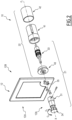
- the encoder 10 comprises a mobile body 21, also called in the example of this figure first body, and a fixed body 22, also called in the example of this figure second body.
- the movable body 21 comprises a button 31 and a rotor 33.
- the button 31 projects relative to the panel 12 and is arranged in the front portion 12A of this panel 12.
- the button 31 is movable in translation along an encoder axis X and in rotation about the encoder axis X. More particularly, the button 31 is movable in a first coding direction C1 which corresponds in this example to the translation direction along the encoder axis X and a second coding direction C2 which corresponds in this example to the rotation direction about the coding axis X.
- the button 31 is movable in each direction according to each coding direction C1, C2.
- the button 31 in the rotation direction, is movable in rotation in the clockwise and counterclockwise directions, and in the translation direction, the button 31 is movable in the direction towards the dashboard and towards the operator.
- the button 31 defines in particular a button surface 34 which is intended to be oriented towards the operator. This surface 34 therefore represents an external surface of the button 31 which is visible to the operator and can be grasped by the operator.
- the rotor 33 extends along the encoder axis X so as to form on one of its ends a solid connection with the button 31.
- the rotor 33 is movable along the first coding direction C1 and along the second coding direction C2 in each aforementioned direction of movement.
- the rotor 33 receives functional internal elements of the movable body 21 which will be explained in more detail later.
- the fixed body 22 comprises a support 41, a cover 42 and a flange 43.
- the flange 43 is for example arranged in a through hole 35 of the panel 12 and makes it possible to support the button 31 and the rotor 33.
- the flange 43 is fixed to the panel 12 while remaining in the rear part 12B thereof, for example using screws accessible from the front part 12B of the panel 12.
- the support 41 receives functional internal elements of the fixed body 22 which are intended to cooperate with the functional internal elements of the mobile body 21 as will be explained in more detail later.
- the functional internal elements of the fixed body 22 are held by the support 41 at a distance from those of the mobile body 21.
- the support 41 is configured to at least partially receive the rotor 33 with the functional internal elements of the mobile body 21 carried by this rotor 33.
- the support 41 is for example connected to the movable body 21 via a movable connection in each coding direction.
- This connection can for example be formed at each end of the rotor 33 and have plain bearings, for example polymer bearings or sintered bronze bearings. These bearings are preferably collared to serve as a mechanical stop. According to another example, these bearings are rolling element bearings such as a ball bushing.
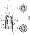
- figure 3 in particular shows the bearings 37 connecting the rotor 33 to the second body 22. In the example of this figure, the bearings 37 connect one end of the rotor 33 directly to the support 41 and the other end of the rotor 33 to the support 41 via the flange 43. In this example, the flange 43 is configured to cooperate with the support 41 in order to fix it to the panel 12
- the cover 42 is intended to protect all of the components of the encoder 10 which are arranged in the rear part 12B of the panel 12.
- the rotor 33 has for example a hollow shaft 45 of cylindrical shape extending along the encoder axis X.
- the functional internal elements of the movable body 21 comprise a first ring 51, called the translation ring, and a second ring 52, called the rotation ring.
- Each of these rings 51, 52 is fixed on the shaft 45 along the encoder axis X and remains spaced from the other ring 51, 52.
- each of these rings 51, 52 has an axial magnetic alternation in the case of the translation ring 51 and a circumferential magnetic alternation in the case of the rotation ring 52.
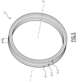
- the translation ring 51 extends along the encoder axis X and has a plurality of elementary rings 51-1, 51-2, 51-3 arranged next to each other, for example by gluing.
- Each elementary ring 51-1, 51-2, 51-3 is for example made in a single block or from several parallelepiped magnets or arc-shaped magnets.
- Such an elementary ring can also come from a “polymagnet” or a “programmable magnet” called Polymagnets ® .
- these elementary rings 51-1, 51-2, 51-3 have a radial magnetization and are arranged next to each other so that the adjacent rings are magnetized in the opposite directions in the radial direction.
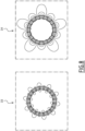
- This arrangement of the elementary rings forms a diagram D1 of the magnetic fluxes illustrated in the figure 6 in the case of five elementary rings.
- an axial magnetic alternation is achieved by using a Halbach type arrangement of which a D2 diagram of the magnetic fluxes is also illustrated in the figure 6 .
- the elementary rings are magnetized alternately according to the radial and circumferential direction.
- the direction of magnetization of each elementary ring is chosen so as to concentrate the magnetic field on the surface of the translation ring 51 opposite the functional internal elements of the fixed body 22.
- such a magnetic field is concentrated on the outer surface of the translation ring 51.
- the translation ring 51 has a width L1 corresponding to its extent along the encoder axis X. This width L1 is formed from a sum of the widths of the elementary rings 51-1, 51-2, 51-3 forming this translation ring 51.
- the width of each elementary ring forms a translational notch pitch.
- the elementary rings have the same width. In such a case, the translation ring 51 has a homogeneous translational notch pitch.
- three elementary rings 51-1, 51-2, 51-3 are arranged successively along the encoder axis X.
- the elementary ring 51-2 is arranged between the elementary rings 51-1, 51-3.
- the elementary ring 51-2 is then called the central ring and the elementary rings 51-1, 51-3 are called the peripheral rings.
- the central ring then has a central notch and the peripheral rings have peripheral notches.
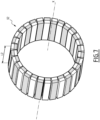
- the rotation ring 52 is illustrated in more detail in the figure 7 . So, and as it is visible on this figure 7 , the rotation ring 52 also extends along the encoder axis X and has a width L2 corresponding to its longitudinal extent.
- the width L2 is greater than the width L1 of the translation ring 51, in particular when the longitudinal extents of all the notching teeth (explained below) are substantially identical.
- the rotation ring 52 is for example of the same diameter as the translation ring 51.
- the circumferential magnetic alternation of the rotation ring 52 is achieved by a particular arrangement of a plurality of elementary parts forming this rotation ring 52, each elementary part having for example a permanent magnet.
- Each elementary part can for example have a substantially parallelepiped shape which is elongated along the encoder axis X. This shape can for example be slightly curved in order to form an arc of a circle around the encoder axis X.
- the elementary parts are arranged next to each other for example by gluing according to the circumferential direction.
- the circumferential extent of each elementary part forms a rotational notch pitch. This is a homogeneous rotational notch pitch when all the elementary parts have the same circumferential extent.
- each elementary part is for example made in a single block or from several parallelepiped magnets or circular arc magnets.
- Such an elementary part can also come from a “polymagnet” or a “programmable magnet” called Polymagnets ® .
- the elementary parts have a radial magnetization and are arranged next to each other so that the adjacent elementary parts are magnetized in the opposite directions in the radial direction.
- This arrangement of the elementary parts forms a D3 diagram of the magnetic fluxes illustrated in the figure 8 .
- a circumferential magnetic alternation is achieved by using a Halbach type arrangement of which a D4 diagram of the magnetic fluxes is also illustrated in the figure 8 .
- the elementary parts are magnetized alternately in the radial and circumferential direction.
- the direction of the magnetization of each elementary part is chosen so as to concentrate the magnetic field on the surface of the rotation ring 52 opposite the functional internal elements of the fixed body 22.
- such a magnetic field is concentrated on the outer surface of the rotating ring 52.
- the functional internals of the fixed body 22 include a pair of translation magnetic sensors 61 also called first magnetic sensors, a pair of rotation magnetic sensors 62, also called second magnetic sensors, a plurality of translational notching teeth 71, also called first notching teeth, and a plurality of rotational notching teeth 72, also called second notching teeth.
- these elements 61, 62, 71, 72 are fixed on an interior surface of the support 41 (not shown in the figure 4 ) of the fixed body 22. Furthermore, as mentioned previously, these elements 61, 62, 71, 72 are kept at a distance from the corresponding rings 51 and 52.
- the pair of magnetic translation detectors 61 is arranged opposite the translation ring 51 and makes it possible to quantify the displacement of this ring 51 along the encoder axis X.
- these detectors 61 make it possible to code each displacement of the translation ring 51 along the encoder axis X by detecting changes in the magnetic flux thanks to the axial magnetic alternation of the elementary rings constituting this translation ring 51.
- the detectors 61 are offset from each other by a fraction of the translation notch pitch defined by this translation ring 51.
- the pair of magnetic rotation detectors 62 is arranged opposite the rotation ring 52.
- the detectors 62 make it possible to quantify each rotary movement of the rotation ring 52 around the encoder axis X by detecting changes in the magnetic flux thanks to the circumferential magnetic alternation implemented by the elementary parts constituting the translation ring 52.
- the magnetic detectors 62 are offset by a fraction of the rotational notch pitch defined by the rotation ring 52.
- Each magnetic detector of each pair has for example a Hall effect sensor or a magnetoresistive sensor or a solenoid. Furthermore, each magnetic detector 61, 62 is connected to an external controller of the encoder 10 by cables 74 visible on the figure 3 .
- the magnetic encoder 10 and in particular the fixed body 22 has a plurality of pairs of magnetic detectors for at least one of the coding directions.
- the detector 10 may comprise two or three pairs of magnetic translation and/or rotation detectors. Doubling or even tripling the number of magnetic detectors makes it possible to improve the reliability of the device.
- Each translational notching tooth 71 is arranged opposite the translational ring 51.
- each translational notching tooth 71 has a surface that is oriented toward the translational ring 51 and has a dimension less than or equal to the translational notching pitch. Such a surface has, for example, a longitudinal extent that is less than or equal to the notching pitch of this ring 51.
- each translational notching tooth 71 is made of a ferromagnetic or magnetic material such as 400 series stainless steel.
- Each translational notching tooth 71 is preferably a magnet.
- Each translational notching tooth 71 is for example a parallelepiped magnet or an arc-shaped magnet. Such a magnet is for example derived from a “polymagnet” or a “programmable magnet” called Polymagnets ® .
- each translational notching tooth 71 defines a stable position in which it is arranged opposite the central elementary ring 51-2. To ensure such a stable position, each translational notching tooth 71 has a magnetization in the opposite direction to that of the outer surface of the central elementary ring 51-2.
- Each rotating notch tooth 72 is arranged opposite the rotation ring 52. As in the previous case, each rotating notch tooth 72 has a surface oriented towards the rotation ring 52 of a dimension less than or equal to that of the rotation notch pitch. In addition, each rotating notch tooth 72 is made of a ferromagnetic or magnetic material such as 400 series stainless steel. Each rotating notch tooth 72 is preferably a magnet. Each rotating notch tooth 72 is for example a parallelepiped magnet or an arc-shaped magnet. Such a magnet is for example derived from a “polymagnet” or a “programmable magnet” called Polymagnets ® .
- the notching teeth associated with the different rings 51, 52 are advantageously connected to each other by a connecting piece 77.
- This connecting piece 77 is for example a magnetic or ferromagnetic piece, and advantageously extends along the encoder axis X.
- a plurality of notching teeth 71, 72 is associated with each of the rings 51, 52.
- at least two notching teeth 72 participate at the same time in the rotational notching, that is to say that a magnetization force is applied at the same time to at least two rotating notching teeth 72.
- three notching teeth are associated with each of the rings.
- the notching teeth are arranged in equidistantly along the circumferential direction of the corresponding ring 51, 52. It should also be understood that a single notching tooth for each ring would be sufficient to provide a notching function along the corresponding direction.
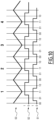
- FIG 10 illustrates an encoding diagram performed by a pair of magnetic translation detectors 61 or rotation detectors 62.
- one of the magnetic detectors of this pair delivers a true or false signal during the movement of the corresponding ring.
- This signal is denoted by the reference S1 on the figure 10 .
- the other detector delivers a signal S2 which is offset relative to the signal S1 by a fraction of the notch pitch.
- This signal S2 is also composed of true and false values which then alternate with the movement of the corresponding ring in the corresponding direction.
- the figure 10 also shows a S3 trace which corresponds to the force or the notching torque provided by one or more notching teeth during the movement of the corresponding ring in the corresponding direction. This S3 trace is then also periodic.
- the encoder 10 comprises a complementary notch controller for further controlling the notch force or torque in at least one of the coding directions.
- This controller comprises in particular a magnetic coil 82 integrated in the fixed body 22 and a toothed wheel 83 integrated in the mobile body 21.
- the coil 82 is mounted inside the support 41 and the toothed wheel 83 is mounted on the rotor 33 just like the rings 51 and 52 previously described.
- the toothed wheel 83 is mounted along the same encoder axis X as the rings 51, 52.
- the toothed wheel 83 is made of a ferromagnetic or magnetic material and is intended to be arranged opposite the magnetic coil 84 when the rotor 33 is received inside the support 41. Like the rings 51, 52, the toothed wheel 83 is intended to be spaced from the coil 82.
- the magnetic coil 82 is adapted to create a magnetic field around the toothed wheel 83.
- This magnetic field is adapted to create a notch during movement, for example in rotation, of the button 31.
- the number of teeth of the toothed wheel 83 is equal to a multiple of the number of notches in rotation of the encoder 10.
- this magnetic field is adapted to create a notch during the translational movement of the button 31.
- the part of the rotor 33 receiving the toothed wheel is notably made of ferromagnetic or magnetic material.
- the fixed body 22 can be completed with one or more ferromagnetic or magnetic parts 84 allowing magnetic closure with the magnetic coil 82.
- the toothed wheel 83 is replaced by any other part made of magnetic or ferromagnetic material on which the magnetic coil 82 is able to act.
- the mobile body 21 may be devoid of such a magnetic or ferromagnetic part.
- the coil 84 is configured to act directly on the shaft 45 which is for example in this case is made entirely of a magnetic or ferromagnetic material.
- the coil 84 is adapted to act directly on at least one of the rings 51, 52.
- the encoder 110 according to a second embodiment will now be explained with reference to the Figures 12 to 16 .
- the application of this encoder 110 is for example identical to that of the encoder 10 explained previously.
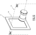
- the main difference of the encoder 110 according to the second embodiment consists in the manner of its arrangement relative to the panel 12. Indeed, as illustrated in the figure 12 , the encoder 110 according to the second embodiment is arranged entirely in the front part 12A of the panel 12.
- the encoder 110 according to the second embodiment comprises a movable body 121, also called the first body, and a fixed body 122, also called the second body.
- the fixed body 122 is fixed for example directly on the front part 12A of the panel 12.
- the fixed body 122 comprises a support 141 receiving the functional internal elements of this fixed body 122 as will be explained in more detail later.
- the support 141 may further comprise a mechanical stop 143 integrated into one of its ends.
- the movable body 121 also comprises a button 131 and a rotor 133 which is for example integral with the button 131 arranged on its end.
- the same end of the rotor 133 is for example closed by a cover 134 having a surface oriented towards the operator.
- the cover 134 is connected to the rotor 133.
- a washer 135 is integral with the fixed body 122 at its end. This washer 135 can have a mechanical stop during the rotation or translation of the movable body 121.
- This mechanical stop can be damped via a return spring or an elastomer part (example of material: EPDM).
- this stop can also be magnetic.
- this stop can be produced by placing a magnet integral with the fixed body in repulsion and in line with a magnet integral with the movable body.
- This magnetic stop is intrinsically damped.
- This magnetic stop may be independent or be part of one of the rings 51, 52, 151 or 152 (in a logic of optimization of the number of parts).
- a magnet of the fixed body can be placed in repulsion and facing the end of this ring having locally an axial or circumferential magnetization.
- the rotor 133 can have bearings 136 intended to cooperate with the fixed body 122 in order to ensure the movement of the mobile body 121 according to each of the coding directions, namely a first coding direction C1 corresponding to the direction of translation along the encoder axis X and a second coding direction C2 corresponding to the direction of rotation around this encoder axis X, in the example of the figures.
- the rotor 133 is intended to at least partially encompass the fixed body 122.
- the rotor 133 is intended to be arranged around the support 141 as can be seen in the figure. figure 14 .
- the movable body 121 comprises a translation ring 151, also called the first ring, and a rotation ring 152, also called the second ring. These rings are similar respectively to the rings 51, 52 described above. Unlike the previous case, the rings 151, 152 according to the second embodiment are arranged on an inner surface of the rotor 133 which then has a hollow rotating shaft according to the example of this figure. Each of these rings 151, 152 is fixed on the shaft 145 along the encoder axis X and remains spaced from the other ring 151, 152.
- the fixed body 122 comprises a plurality of pairs of magnetic detectors 161, 162 and a plurality of notching teeth 171, 172.
- the pairs of magnetic detectors 161, 162 comprise at least one pair of magnetic translation detectors 161 arranged opposite the translation ring 151 and one pair of magnetic rotation detectors 162 arranged opposite the rotation ring 152.
- the notching teeth 171, 172 comprise at least one translation notching tooth 171 arranged opposite the translation ring 151 and one rotation notching tooth 172 arranged opposite the rotation ring 152.
- a plurality of notching teeth 171, 172 is associated with each of the rings 151, 152. In this case, at least two notching teeth 172 participate at the same time in the rotational notching, that is to say that a magnetization force is applied at the same time to at least two rotating notching teeth 172.
- the functional internal elements 161, 162, 171, 172 of the fixed body 122 of the encoder 110 according to the second embodiment are arranged on an outer surface of the support 141.
- these elements are arranged opposite the inner surfaces of the corresponding rings 151, 152.
- the functional internal elements of the fixed body 122 are received inside the rings 151, 152, while remaining at a distance from them.
- the operation and respective arrangement of these internal elements 161, 162, 171, 172 are similar to those described previously in relation to the first embodiment.
- a visual feedback element 190 is integrated on the surface 134 of the button 131.
- the visual feedback element 190 may for example comprise an indicator indicating for example the function of the encoder 110 or an annunciator indicating the validation of the command or any other ambient light.
- This ambient light can for example be connected to the rest of the cockpit to create a harmony to improve the aesthetic appearance of the button 131 of the encoder 110.
- the light indication in the event of an emergency or turbulence can represent an asset from the point of view of aircraft safety.
- This lighting can be connected and synchronized with the rest of the cockpit. In this case, it could change color depending on the context during the flight, for example red flashing in an emergency situation.
- the functional element comprises a presence sensor
- the latter may be integrated into the button 131 to activate additional functions and/or to detect finger positions on the button.
- the functionality of the encoder 110 may be modified depending on the number of fingers placed on the surface 134.
- the functional element comprises a haptic actuator
- the latter is preferably placed at the end of the button 131 to improve the haptic feeling by the user. It may have a piezoelectric actuator or an unbalanced vibration motor preferably secured to the fixed body 122.
- the actuator may also be an electromagnetic actuator and act between the fixed body 122 and the mobile body 121.
- the electromagnetic actuator may use a winding or a coil secured to the fixed body 122 which generates a magnetic field which attracts or repels a ferromagnetic or magnetic part along the encoder axis X. This latter part may be independent or be a part of one of the rings 151, 152.
- one or more of the functional elements may be disposed inside the rotor 133 and the support 141.
- the cables 174 connecting these functional elements may extend inside the rotor 133 to an external controller.
- At least one of the aforementioned functional elements can also be arranged in the encoder 10 according to the first embodiment.
- a notching controller similar to that described in relation to the first embodiment embodiment may also be arranged in the encoder 110 according to the second embodiment. It is also clear that it is possible to arrange the encoder 10 as described in relation to the first embodiment entirely in the front portion 12A of the panel 12. It is also possible to arrange the encoder 110 as described in relation to the second embodiment partially in the rear portion 12B and partially in the front portion 12A of the panel 12.
Landscapes
- Engineering & Computer Science (AREA)
- Physics & Mathematics (AREA)
- General Physics & Mathematics (AREA)
- General Engineering & Computer Science (AREA)
- Theoretical Computer Science (AREA)
- Human Computer Interaction (AREA)
- Automation & Control Theory (AREA)
- Transmission And Conversion Of Sensor Element Output (AREA)
Description
- La présente invention concerne un codeur magnétique incrémental.
- Plus particulièrement, la présente invention concerne un codeur apte à fournir des signaux logiques binaires représentant des incréments de position relative de deux éléments du codeur, les deux éléments étant mobiles l'un par rapport à l'autre. Avantageusement, un tel codeur est applicable dans le domaine aéronautique, par exemple dans un cockpit de pilotage d'un aéronef.
- Typiquement, dans une application pour des équipements aéronautiques, on peut utiliser un codeur angulaire et/ou linéaire pour indiquer à un calculateur de pilotage automatique une consigne d'altitude ou de vitesse que l'opérateur choisit en actionnant un bouton de commande du codeur. La fiabilité du codeur et des informations qu'il délivre est alors un élément essentiel du codeur. Le besoin typique pour un codeur aéronautique peut comprendre un ou plusieurs des éléments suivants : compacité, capacité d'effectuer des multi-tours en rotation et/ou une course linéaire, capacité d'incrémentation et de crantage, etc. Afin de permettre sa certification, le codeur aéronautique doit également pouvoir répondre à des niveaux de sécurité DAL (de l'anglais « Design Assurance Level ») élevés, notamment au niveau DAL A.
- En particulier, en ce qui concerne la compacité, un codeur présente typiquement un bouton de commande de diamètre entre 10 à 100 mm et de longueur entre 5 et 50 mm (typiquement Ø 16 mm x Ig 16 mm) et un corps de diamètre entre 10 à 100 mm et de longueur entre 5 et 100 mm (typiquement Ø 25 mm x Ig 50 mm) caché derrière le panneau de fixation ou fixé devant ce panneau. Dans ce dernier cas, le bouton englobe le corps du codeur qui est fixé sur le panneau et permet d'être placé autour, voire légèrement en chevauchement d'un moniteur ou écran.
- En ce que concerne la capacité d'incrémentation, chaque passage de cran (ou pas) constitue un incrément d'une unité de comptage de la rotation ou de la translation. La résolution angulaire ou linéaire est définie pas le pas (ou cran). Le nombre de pas par tour est de l'ordre de 1 à 32 pas (typiquement 12 pas). Le nombre de pas en translation est de 1 à 10 crans (typiquement 1 cran dans chaque direction pour obtenir un bouton « push/pull » avec un état stable entre les deux crans).
- Pour détecter le sens du mouvement en rotation et/ou en translation, le codeur dispose généralement d'au moins deux détecteurs (respectivement pour la rotation et la translation) décalés physiquement entre eux (typiquement un nombre impair de quart de pas). Ces deux détecteurs permettent l'encodage du mouvement en rotation et/ou en translation sur deux bits. Ainsi, l'encodage donne les valeurs successives suivantes : 00, 01, 11, 10 lorsque le codeur tourne et/ou translate dans un sens et les valeurs successives suivantes : 00, 10, 11, 01 lorsque le codeur tourne et/ou translate dans l'autre sens. Il est donc possible de déterminer non seulement l'apparition d'un incrément en rotation et/ou en translation (changement d'état de l'un des bits) mais aussi le sens de rotation (par comparaison entre un état détecté et l'état immédiatement antérieur).
- En ce qui concerne la capacité de crantage des codeurs, le passage de cran encodé entraîne généralement un retour tactile qu'un opérateur doit ressentir lors de la manoeuvre du dispositif. Le couple de crantage angulaire peut par exemple être de l'ordre de 1 à 700 mN.m (typiquement 12 mN.m) et l'effort de crantage linéaire de l'ordre de 0,5 à 20 N (typiquement 6 N).
- Les codeurs les plus complexes disposent d'encodage et de crantage en rotation et en translation. L'encodage et le crantage en rotation ne doivent pas être bloqués par ceux en translation. Dans ce cas, la détection et le crantage en rotation et en translation doivent pouvoir être utilisés simultanément sans perte de performance. Par exemple, pour saisir une vitesse, le pilote devra simultanément pousser le bouton du codeur et le tourner jusqu'à la valeur choisie.
- Enfin, dans certain cas, pour sécuriser le codeur et notamment pour garantir son niveau de sécurité DAL (par exemple DAL A), les fonctions de détection (ou d'encodage) sont au moins doublées.
- Pour répondre aux besoins précités, les codeurs utilisés dans les applications aéronautiques sont souvent basés sur des solutions opto-mécaniques (détection optique et crantage mécanique) ou électromécanique (détection par contact électrique et crantage mécanique) et parfois magnéto-mécanique (détection magnétique et crantage mécanique) ou opto-magnétique ou même purement magnétique.
- Par exemple, des codeurs opto-mécaniques sont décrits dans les documents
FR 2937129 FR 2954491 - Plus généralement, les solutions actuelles à crantage mécanique génèrent de la friction (exemple : bille contre came) et de l'usure ce qui limite la durée de vie du dispositif, notamment lorsque des pièces en plastique sont utilisées. Dans les codeurs électromécaniques, la détection et le crantage sont parfois liés par au moins une pièce mécanique commune qui sert à la fois au click et à la détection via un contact électrique. Ce dernier est souvent exposé au risque d'usure, de « fretting corrosion » (corrosion de contact) et limite la durée de vie du dispositif. De plus, dans les dispositifs opto-mécaniques et parfois électromécaniques, la détection et le crantage sont découplés, c'est-à-dire qu'ils résultent de solution et/ou phénomène différents et sont assez éloignés physiquement. Ce découplage augmente le nombre de pièces et par conséquent, le risque de décalage entre la détection et le crantage. Dans le cas de codeur complexe et sécurisé, le nombre de pièces est encore plus important. Dans ce cas, pour assurer une bonne performance et fiabilité, les codeurs complexes actuels requièrent des pièces de grande précision qui sont plus coûteuses.
- On connait également le document
FR 2370350 - En résumé, les solutions électromécaniques présentent le plus fort risque de fatigue tant au niveau du crantage que de l'encodage car elles génèrent le plus de frottement. Par ailleurs, l'encodage électrique est exposé à la corrosion de contact (« fretting corrosion »). Ces inconvénients diminuent la fiabilité et limitent la durée de vie du dispositif.
- Les solutions opto-mécaniques et magnéto-mécaniques conservent le risque de fatigue au niveau du crantage mécanique.
- Les solutions opto-magnétiques utilisent des phénomènes sans contact différents. Ces solutions sont plus encombrantes si on souhaite faire un codeur plus complexe (exemple : codeur rotatif avec « push/pull ») et sécurisé.
- Enfin, les solutions purement magnétiques ne permettent pas de répondre à l'ensemble des besoins précités.
-
FR 3 062 935 A1 -
FR 3 089 314 A1 WO2021/023951 A1 etUS 2004/0100440 A1 décrivent d'autres exemples connus de modules de commande comprenant une détection magnétique de position et des moyens magnétiques de retour tactile. - La présente invention a pour but de proposer un codeur incrémental répondant à l'ensemble des besoins précités (compacité, capacité d'effectuer des multi-tours en rotation et/ou une course linéaire, capacité d'incrémentation et de crantage, etc.), tout en présentant des fonctions de crantage et de détection (codage) sans friction et sans usure, un nombre de pièces limité, un montage simplifié et des risques diminués de blocage et de décalage.
- A cet effet, l'invention concerne un codeur magnétique incrémental comme défini par la revendication 1, définissant un axe de codeur et comprenant un corps fixe et un corps mobile par rapport au corps fixe selon au moins une première direction de codage correspondant à une translation le long de l'axe de codeur selon une longueur de course en translation prédéterminée, le corps mobile étant mobile par rapport au corps fixe selon en outre une deuxième direction de codage perpendiculaire à la première direction de codage et correspondant à une rotation autour de l'axe de codeur.
- L'un des corps, dit premier corps, comprend:
- un premier anneau s'étendant selon une première direction longitudinale confondue avec l'axe de codeur et une première direction circonférentielle perpendiculaire à la première direction longitudinale, la première direction longitudinale correspondant à la première direction de codage, le premier anneau définissant une alternance magnétique selon la première direction de codage;
- un deuxième anneau s'étendant selon une deuxième direction longitudinale confondue avec l'axe de codeur et une deuxième direction circonférentielle perpendiculaire à la deuxième direction longitudinale, la deuxième direction circonférentielle correspondant à la deuxième direction de codage, le deuxième anneau définissant une alternance magnétique selon la deuxième direction de codage.
- L'autre corps, dit deuxième corps, comprend:
- au moins une première dent de crantage en matériau ferromagnétique ou magnétique disposée en regard du premier anneau pour créer un crantage lors d'un mouvement du corps mobile selon la première direction de codage;
- une première paire de détecteurs magnétiques disposés en regard du premier anneau et configurés pour quantifier chaque mouvement du corps mobile selon la première direction de codage;
- au moins une deuxième dent de crantage en matériau ferromagnétique ou magnétique disposée en regard du deuxième anneau pour créer un crantage lors d'un mouvement du corps mobile selon la deuxième direction de codage; et
- une deuxième paire de détecteurs magnétiques disposés en regard du deuxième anneau et configurés pour quantifier chaque mouvement du corps mobile selon la deuxième direction de codage.
- Muni de ces caractéristiques, le codeur selon l'invention permet en effet de mettre en oeuvre un codage selon l'une des directions choisies, par exemple parmi la direction de translation et la direction de rotation, tout en assurant un crantage selon la même direction. Selon l'invention, le codage et le crantage sont créés par le même effet magnétique entre le corps mobile et le corps fixe.
- Ainsi, l'arrangement de ces deux corps peut être choisi de sorte à minimiser leur contact mécanique. Par exemple, les éléments détaillés ci-dessus du corps fixe et du corps mobile ne présentent aucun contact entre eux. Ainsi, ces éléments fonctionnent sans friction et sans usure mécanique prématurée. Cela garantit donc la fiabilité à l'usage du codeur et rallonge considérablement sa durée de vie même lorsque des pièces en plastique sont utilisées. De plus, ces éléments sont en nombre limité ce qui permet de les disposer facilement au sein des corps correspondants.
- Cela fait alors le montage du codeur particulièrement simple et diminue les risques de blocage et de décalage de différentes pièces entre elles.
- Grâce à ces caractéristiques, il est possible de mettre en oeuvre le codage et le crantage par le codeur magnétique selon l'invention, selon deux directions de codage différentes. Ainsi, il est possible par exemple de mettre en oeuvre le codage et le crantage dans la direction de rotation et de translation simultanément. Une telle application correspond notamment à une application conventionnelle d'un codeur dans le cockpit d'un aéronef.
- De plus, le codage et le crantage selon les deux directions précitées sont mis en oeuvre en utilisant le même phénomène physique, à savoir le magnétisme, qui permet d'éviter les contacts et donc les frottements entre différentes pièces et par conséquent, leur usure prématurée. Ainsi, les avantages précités par rapport à une seule direction de codage peuvent être appliqués également aux deux directions de codage.
- Selon encore d'autres modes de réalisation, le codeur selon l'invention présente plus que deux directions de codage et avantageusement, de crantage.
- Selon certains modes de réalisation, les dents de crantage sont reliées rigidement entre elles par une pièce de raccordement, avantageusement faite d'un matériau ferromagnétique ou magnétique.
- Ces caractéristiques permettent d'améliorer l'efficacité du codeur. En particulier, cela permet d'augmenter le couple et la force de crantage sans augmenter la taille des dents de crantage. Ainsi, il est possible d'éviter les fuites du champ magnétique et les émissions parasites externes.
- Dans certains modes de réalisation, la première direction de codage correspond à une translation le long de l'axe de codeur selon une longueur de course en translation prédéterminée et la deuxième direction de codage correspond à une rotation autour de l'axe de codeur.
- Muni de ces caractéristiques, le codeur selon l'invention peut être utilisé de manière conventionnelle dans le cockpit d'un aéronef.
- Selon certains modes de réalisation, l'étendue longitudinale du deuxième anneau est choisie de sorte que le champ magnétique vu par le ou chaque deuxième dent de crantage et par la deuxième paire de détecteurs magnétiques est sensiblement constant sur toute la longueur de course en translation.
- Selon ces caractéristiques, le champ magnétique vu par la ou chaque dent associée à l'anneau de rotation ainsi que par la paire de détecteurs correspondants soit sensiblement constant à un angle de rotation donné et sur toute la longueur de course en translation du codeur noté Ct. Si chaque deuxième dent de crantage est centrée sur l'anneau correspondant, alors la longueur Ct est égale à deux fois la longueur de course dans chaque direction. Par conséquent, la détection et le crantage en rotation et en translation peuvent être utilisés simultanément sans perte de performance du codeur.
- De manière générale, la formule suivante doit être respectée : L2 ≥ Ldr + Ct où L2 désigne l'étendue longitudinale du deuxième anneau et Ldr l'étendue longitudinale de la ou de chaque deuxième dent de crantage. Dans le cas où l'étendue longitudinale des premières et deuxièmes dents de crantage sont sensiblement égales, l'étendue longitudinale du deuxième anneau est sensiblement supérieure à celle du premier anneau. En effet, si on considère que L1 ≈ Ldt + Ct (Ldt désignant l'étendue longitudinale de la ou de chaque première dent de crantage) et Ldt = Ldr, alors L2 ≥ L1.
- Selon certains modes de réalisation, le premier anneau définit au moins un cran central et deux crans périphériques, une position stable en translation étant définie lorsque la première dent de crantage est disposée en regard du cran central.
- Grâce à ces caractéristiques, il est possible d'atteindre les fonctions du type push/pull dans le sens de translation du codeur selon l'invention. En particulier, ces caractéristiques permettent d'avoir une position stable lorsque la dent de crantage associée à l'anneau de translation est positionnée face au cran central. Une telle position stable est atteinte sans utilisation des moyens mécaniques de rappel, tels que des ressorts ou d'autres éléments élastiques. Ainsi, il est possible d'éviter de frottements parasites lors du fonctionnement du codeur.
- Il est donc possible pour l'opérateur d'appuyer sur le codeur ou alors de tirer celui-ci, tout en permettant d'introduire des informations en faisant une rotation dans l'une des positions précitées de ce codeur.
- Selon certains modes de réalisation, l'alternance magnétique du ou de chaque anneau) définit un pas de crantage constant.
- Muni de ces caractéristiques, le ou chaque anneau peut être fabriqué de manière simple. De plus, cela crée des crantages homogènes tout au long du mouvement du codeur selon la direction correspondante.
- Selon certains modes de réalisation, la surface de la ou de chaque dent de crantage présente une étendue inférieure ou égale au pas de crantage de l'anneau correspondant.
- Muni de ces caractéristiques, le nombre de dents peut ainsi être augmenté jusqu'à atteindre le nombre d'alternances magnétiques des anneaux. Cela permet alors d'optimiser l'effort de crantage.
- Dans certains modes de réalisation, les détecteurs magnétiques d'une même paire de détecteurs sont décalés l'un de l'autre d'une fraction du pas de crantage de l'anneau correspondant.
- Grâce à ces caractéristiques, il est possible de détecter le sens de mouvement du codeur selon la direction de codage correspondante. Par exemple, lorsqu'il s'agit de la direction de rotation, un tel arrangement des détecteurs permet de détecter le sens de rotation du codeur. Lorsqu'il s'agit de la direction de translation, un tel arrangement des détecteurs permet de détecter le sens de mouvement en translation du codeur.
- Selon certains modes de réalisation, le deuxième corps comprend pour au moins un anneau, une pluralité de dents de crantage en matériau ferromagnétique ou magnétique disposée en regard de cet anneau pour créer un crantage lors d'un mouvement du corps mobile selon la direction de codage correspondante ;
avantageusement, lesdites dents de crantage étant réparties de manière équidistante selon la direction circonférentielle correspondante. - Une pluralité de dents de crantage associée à un même anneau permet d'augmenter la force et/ou le couple de crantage. Il est ainsi possible d'atteindre le couple de force souhaité lors du crantage. De plus, lorsque ces dents sont réparties de manière équidistante, il est possible de rendre cet effort et/ou ce couple homogène lors de chaque crantage.
- Selon certains modes de réalisation, comprenant en outre une butée de course pour la ou chaque direction de codage.
- Muni de ces caractéristiques, il est possible d'assurer une butée selon la ou chaque direction de codage du codeur.
- Selon certains modes de réalisation, le premier corps est le corps mobile et le deuxième corps est le corps fixe.
- Le ou chaque anneau est présent dans le corps mobile alors que la ou chaque dent ainsi que la ou chaque paire de détecteurs magnétiques sont présentes dans le corps fixe. Cela est avantageux dans la mesure où les câbles électriques issus notamment des détecteurs magnétiques restent fixes. Cela évite un câblage compliqué qui est généralement coûteux et présente des risques d'usure et de coupure du signal.
- Selon certains modes de réalisation, le corps fixe est destiné à être fixé devant un panneau formant un tableau de bord et le corps fixe est englobé au moins partiellement par le corps mobile.
- Grâce à ces caractéristiques, le codeur selon l'invention peut être fixé de manière particulière simple par exemple sur une planche de bord du cockpit d'un aéronef.
- Selon certains modes de réalisation, le corps fixe est destiné à être fixé derrière un panneau formant un tableau de bord et le corps fixe englobe au moins partiellement par le corps mobile.
- Grâce à ces caractéristiques, le codeur selon l'invention peut être disposé de manière compacte par exemple dans le cockpit d'un aéronef car seule la partie mobile fait saillie par rapport au panneau formant la planche de bord.
- Selon certains modes de réalisation, comprenant en outre un bouton destiné à être orienté vers un opérateur ;
ledit bouton comprenant au moins un élément fonctionnel choisi dans la liste comprenant : - un élément de retour visuel ;
- un capteur de présence ;
- un actionneur haptique.
- Grâce à ces caractéristiques, il est possible d'assurer un certain nombre de fonctionnalités supplémentaires du codeur. Par exemple, il est possible de mettre en oeuvre un retour visuel indiquant par exemple à l'opérateur l'état courant du codeur ou toute autre information utile, telle que par exemple la fonction affectée au codeur.
- Grâce au capteur de présence il est possible par exemple d'activer des fonctions complémentaires du codeur en détectant la position des doigts sur le bouton. Par exemple, les fonctionnalités du codeur peuvent différer en fonction du nombre de doigts posés sur le bouton.
- Grâce à un actionneur haptique il est possible d'améliorer le ressenti haptique par l'utilisateur.
- Selon certains modes de réalisation, le codeur comprend en outre un contrôleur des crantages complémentaire comprenant une bobine électromagnétique solidaire de l'un des corps et configurée pour agir sur au moins une dent de crantage et/ou un élément ferromagnétique ou magnétique solidaire de l'autre corps.
- Grâce à ces caractéristiques, il est possible d'augmenter l'effort et le couple de crantage ressentis par l'opérateur.
- Ces caractéristiques et avantages de l'invention apparaitront à la lecture de la description qui va suivre donnée uniquement à titre d'exemple et non limitatif, et faite en référence aux dessins annexés, sur lesquels :
- [
Fig.1 ] lafigure 1 est une vue schématique en perspective d'un codeur magnétique selon un premier mode de réalisation de l'invention, le codeur étant fixé partiellement derrière un panneau formant une planche de bord ; - [
Fig.2 ] lafigure 2 est une vue en perspective éclatée du codeur de lafigure 1 ; - [
Fig.3 ] lafigure 3 présente une vue partielle d'une coupe selon le plan longitudinal III de lafigure 1 et de trois autres coupes le long de l'axe de codeur de lafigure 1 ; - [
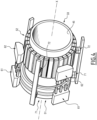
Fig.4 ] lafigure 4 est une vue en perspective des éléments internes fonctionnels du corps fixe et du corps mobile de lafigure 1 , ces éléments comprenant notamment un anneau de translation, un anneau de rotation, une pluralité de dents de crantage et deux paires de détecteurs magnétiques ; - [
Fig.5 ] lafigure 5 est une vue schématique en perspective de l'anneau de translation de lafigure 4 ; - [
Fig.6 ] lafigure 6 est un diagramme de rayonnement magnétique en fonction de différents exemples d'arrangement des anneaux élémentaires de l'anneau de translation de lafigure 5 ; - [
Fig.7 ] lafigure 7 est une vue schématique en perspective de l'anneau de rotation de lafigure 4 ; - [
Fig.8 ] lafigure 8 est un diagramme de rayonnement magnétique selon différents exemples d'arrangement des éléments formant l'anneau de rotation de lafigure 7 ; - [
Fig.9 ] lafigure 9 est une vue schématique en perspective des dents de crantage et des paires de détecteurs magnétiques de lafigure 4 ; - [
Fig.10 ] lafigure 10 est un diagramme illustrant le fonctionnement d'une paire de détecteurs magnétiques de lafigure 9 avec un effort de crantage ; - [
Fig.11 ] lafigure 1 1 est une vue en perspective éclatée du codeur de lafigure 1 dans lequel un contrôleur de crantage complémentaire a été rajouté ; - [
Fig.12 ] lafigure 12 est une vue schématique en perspective d'un codeur selon un deuxième mode de réalisation de l'invention, le codeur étant fixé sur un panneau formant une planche de bord tout en restant devant ce panneau ; - [
Fig.13 ] lafigure 13 est une vue en perspective éclatée du codeur de lafigure 12 ; - [
Fig.14 ] lafigure 14 présente une vue partielle d'une coupe selon le plan longitudinal XIV de lafigure 12 et de trois autres coupes le long de l'axe de codeur de lafigure 12 ; - [
Fig.15 ] lafigure 15 est une vue schématique en perspective d'un exemple d'arrangement des éléments internes fonctionnel du corps fixe et du corps mobile du codeur de lafigure 12 ; - [
Fig.16 ] lafigure 16 présente une vue partielle d'une coupe selon le plan longitudinal XVI du codeur de lafigure 12 et d'une autre coupe le long de l'axe de codeur de lafigure 12 , le codeur comprenant au moins un élément fonctionnel supplémentaire. - La
figure 1 illustre en effet un codeur magnétique incrémental 10 selon un premier mode de réalisation de l'invention. De préférence, le codeur 10 est monté dans un cockpit permettant de piloter un aéronef. - Par « aéronef », on entend tout engin volant, tel qu'un avion, un hélicoptère ou un drone par exemple. Un tel aéronef peut être piloté directement à partir de celui-ci. Dans un tel cas le cockpit est avantageusement arrangé à l'intérieur de l'aéronef. Selon un autre exemple de réalisation, un tel aéronef est contrôlé à distance. Dans un tel cas, le cockpit est disposé à distance de l'aéronef et présente par exemple une station au sol. Dans tous les cas, l'aéronef est configuré pour être piloté par un opérateur, par exemple par un pilote à partir du cockpit disposé à l'intérieur de l'aéronef.
- Selon l'invention, le codeur 10 permet à l'opérateur de contrôler au moins une fonctionnalité avionique. Par exemple, un tel codeur 10 peut être utilisé par l'opérateur pour contrôler un système avionique et fait partie d'un système de contrôle d'un tel système avionique. En variante, le codeur 10 fait partie d'un système de contrôle de plusieurs systèmes avioniques. Par exemple, le codeur 10 selon l'invention fait partie d'un système dit « Flight Control Unit » (FCU) ou « Integrated Standby Instrument System » (ISIS) ou « Closer Control Device » (CCD) ou « Keyboard Cursor Control Device » (KCCD), etc.
- Dans l'exemple de la
figure 1 , le codeur 10 est intégré partiellement dans un panneau 12. Ce panneau 12 forme par exemple une planche de bord du cockpit de l'aéronef pour l'un des systèmes de contrôle précité. Dans l'exemple de lafigure 1 , le codeur 10 est arrangé partiellement dans la partie avant 12A du panneau 12 et partiellement dans la partie arrière 12B de ce panneau 12. En particulier, dans l'exemple de lafigure 1 , la partie avant 12A du panneau 12 est orientée vers l'opérateur alors que la partie arrière 12B de ce panneau est orientée vers la partie interne de la planche de bord. Bien entendu, d'autres exemples d'arrangement du codeur 10 par rapport au panneau 12 ou par rapport à tout autre moyen de fixation sont également possibles. - En référence à la
figure 2 , le codeur 10 comprend un corps mobile 21, appelé également dans l'exemple de cette figure premier corps, et un corps fixe 22, appelé également dans l'exemple de cette figure deuxième corps. - Le corps mobile 21 comprend un bouton 31 et un rotor 33.
- Le bouton 31 fait saillie par rapport au panneau 12 et est arrangé dans la partie avant 12A de ce panneau 12. Le bouton 31 est mobile en translation le long d'un axe de codeur X et en rotation autour de l'axe de codeur X. Plus particulièrement, le bouton 31 est mobile selon une première direction de codage C1 qui correspond dans cet exemple à la direction de translation selon l'axe de codeur X et une deuxième direction de codage C2 qui correspond dans cet exemple à la direction de rotation autour de l'axe de codage X. Avantageusement, le bouton 31 est mobile dans chaque sens selon chaque direction de codage C1, C2. En particulier, dans la direction de rotation, le bouton 31 est mobile en rotation dans le sens horaire et antihoraire, et dans la direction de translation, le bouton 31 est mobile dans le sens vers la planche de bord et vers l'opérateur. Avantageusement, le bouton 31 définit notamment une surface de bouton 34 qui est destinée à être orientée vers l'opérateur. Cette surface 34 représente donc une surface extérieure du bouton 31 qui est visible par l'opérateur et peut être saisie par l'opérateur.
- Le rotor 33 s'étend selon l'axe de codeur X de sorte à former sur l'une de ses extrémités une liaison solidaire avec le bouton 31. Ainsi, tout comme le bouton 31, le rotor 33 est mobile selon la première direction de codage C1 et selon la deuxième direction de codage C2 dans chaque sens de mouvement précité. Le rotor 33 reçoit des éléments internes fonctionnels du corps mobile 21 qui seront expliqués plus en détail par la suite.
- Le corps fixe 22 comprend un support 41, un capot 42 et une flasque 43.
- La flasque 43 est par exemple disposée dans un trou passant 35 du panneau 12 et permet de supporter le bouton 31 et le rotor 33. Dans l'exemple de la
figure 2 , la flasque 43 est fixée sur le panneau 12 tout en restant dans la partie arrière 12B de celui-ci, en utilisant par exemple des vis accessibles à partir de la partie avant 12B du panneau 12. - Le support 41 reçoit des éléments internes fonctionnels du corps fixe 22 qui sont destinés à coopérer avec les éléments internes fonctionnels du corps mobile 21 comme cela sera expliqué plus en détail par la suite. En particulier, et comme cela sera apparent par la suite, les éléments internes fonctionnels du corps fixe 22 sont maintenus par le support 41 à distance par rapport à ceux du corps mobile 21. Pour ce faire, le support 41 est configuré pour recevoir au moins partiellement le rotor 33 avec les éléments internes fonctionnels du corps mobile 21 portés par ce rotor 33.
- Le support 41 est par exemple relié au corps mobile 21 via une liaison mobile dans chaque direction de codage. Cette liaison peut par exemple être formée à chaque extrémité du rotor 33 et présenter des paliers lisses, par exemple des paliers en polymère ou paliers bronze frittés. Ces paliers sont préférentiellement à collerette pour servir de butée mécanique. Selon un autre exemple, ces paliers sont des paliers à élément roulant tel que douille à billes. La
figure 3 fait notamment apparaitre les paliers 37 reliant le rotor 33 au deuxième corps 22. Dans l'exemple de cette figure, les paliers 37 relient une extrémité du rotor 33 directement au support 41 et l'autre extrémité du rotor 33 au support 41 via la flasque 43. Dans cet exemple, la flasque 43 est configurée pour coopérer avec le support 41 afin de le fixer au panneau 12 - Le capot 42 est destiné à protéger l'ensemble des composants du codeur 10 qui sont disposés dans la partie arrière 12B du panneau 12.
- Dans l'exemple de la
figure 4 illustrant plus en détail les éléments internes fonctionnels du corps fixe 22 et du corps mobile 21, le rotor 33 présente par exemple un arbre 45 creux de forme cylindrique s'étendant selon l'axe de codeur X. - En référence à cette
figure 4 , les éléments internes fonctionnels du corps mobile 21 comprennent un premier anneau 51, dit anneau de translation, et un deuxième anneau 52, dit anneau de rotation. Chacun de ces anneaux 51, 52 est fixé sur l'arbre 45 le long de l'axe de codeur X et reste espacé de l'autre anneau 51, 52. En outre, chacun de ces anneaux 51, 52 présente une alternance magnétique axiale dans le cas de l'anneau de translation 51 et circonférentielle dans le cas de l'anneau de rotation 52. - La
figure 5 illustre plus en détail l'anneau de translation 51. Ainsi, en référence à cettefigure 5 , l'anneau de translation 51 s'étend selon l'axe de codeur X et présente une pluralité d'anneaux élémentaires 51-1, 51-2, 51-3 disposés l'un à côté de l'autre, par exemple par collage. Chaque anneau élémentaire 51-1, 51-2, 51-3 est par exemple réalisé en un seul bloc ou à partir de plusieurs aimants parallélépipédiques ou d'aimants en arc de cercle. Un tel anneau élémentaire peut également être issu d'un « polyaimants » ou d'un « aimant programmable » nommé Polymagnets®. - Afin d'atteindre une alternance magnétique axiale, dans l'exemple de la
Figure 5 , ces anneaux élémentaires 51-1, 51-2, 51-3 présentent une aimantation radiale et sont disposés l'un à côté de l'autre de sorte que les anneaux adjacents soient magnétisés dans les sens opposés selon la direction radiale. Cette disposition des anneaux élémentaires forme un diagramme D1 des flux magnétiques illustré sur lafigure 6 dans le cas de cinq anneaux élémentaires. - Selon un autre exemple de disposition possible, une alternance magnétique axiale est atteinte en utilisant un arrangement de type Halbach dont un diagramme D2 des flux magnétiques est illustré également sur la
figure 6 . En particulier, selon un tel type d'arrangement, les anneaux élémentaires sont magnétisés alternativement selon la direction radiale et circonférentielle. Par ailleurs, le sens de la magnétisation de chaque anneau élémentaire est choisi de sorte à concentrer le champ magnétique sur la surface de l'anneau de translation 51 en regard des éléments internes fonctionnels du corps fixe 22. Dans l'exemple de l'arrangement respectif du corps mobile 21 et du corps fixe 22 de lafigure 4 , un tel champ magnétique est concentré sur la surface extérieure de l'anneau de translation 51. - L'anneau de translation 51 présente une largeur L1 correspondant à son étendue selon l'axe de codeur X. Cette largeur L1 est formée d'une somme des largeurs des anneaux élémentaires 51-1, 51-2, 51-3 formant cet anneau de translation 51. La largeur de chaque anneau élémentaire forme un pas de crantage en translation. Selon un exemple de réalisation, les anneaux élémentaires présentent une même largeur. Dans un tel cas, l'anneau de translation 51 présente un pas de crantage en translation homogène.
- Dans l'exemple de la
figure 5 , trois anneaux élémentaires 51-1, 51-2, 51-3 sont arrangés successivement le long de l'axe de codeur X. Parmi ces anneaux élémentaires 51-1, 51-2, 51-3, l'anneau élémentaire 51-2 est disposé entre les anneaux élémentaires 51-1, 51-3. L'anneau élémentaire 51-2 est alors appelé anneau central et les anneaux élémentaires 51-1, 51-3 sont appelés anneaux périphériques. L'anneau central présente alors un cran central et les anneaux périphériques présentent des crans périphériques. - L'anneau de rotation 52 est illustré plus en détail sur la
figure 7 . Ainsi, et comme cela est visible sur cettefigure 7 , l'anneau de rotation 52 s'étend également selon l'axe de codeur X et présente une largeur L2 correspondant à son étendue longitudinale. Avantageusement, selon l'invention, la largeur L2 est supérieure à la largeur L1 de l'anneau 51 de translation, notamment lorsque les étendues longitudinales de toutes les dents de crantage (expliquées ci-dessous) sont sensiblement identiques. L'anneau de rotation 52 est par exemple de même diamètre que l'anneau de translation 51. - L'alternance magnétique circonférentielle de l'anneau de rotation 52 est atteinte par une disposition particulière d'une pluralité de pièces élémentaires formant cet anneau de rotation 52, chaque pièce élémentaire présentant par exemple un aimant permanent. Chaque pièce élémentaire peut par exemple présenter une forme sensiblement parallélépipédique qui est allongée selon l'axe de codeur X. Cette forme peut par exemple être légèrement incurvée afin de former un arc de cercle autour de l'axe de codeur X. Les pièces élémentaires sont disposées l'une à côté de l'autre par exemple par collage selon la direction circonférentielle. L'étendue circonférentielle de chaque pièce élémentaire forme un pas de crantage en rotation. Il s'agit d'un pas de crantage en rotation homogène lorsque l'ensemble des pièces élémentaires présentent une même étendue circonférentielle. Comme dans le cas des anneaux élémentaires, chaque pièce élémentaire est par exemple réalisée en un seul bloc ou à partir de plusieurs aimants parallélépipédiques ou d'aimants en arc de cercle. Une telle pièce élémentaire peut également être issue d'un « polyaimants » ou d'un « aimant programmable » nommé Polymagnets®.
- Dans l'exemple de la
figure 7 , les pièces élémentaires présentent une aimantation radiale et sont disposés l'une à côté de l'autre de sorte que les pièces élémentaires adjacentes soient magnétisées dans les sens opposés selon la direction radiale. Cette disposition des pièces élémentaires forme un diagramme D3 des flux magnétiques illustré sur lafigure 8 . - Selon un autre exemple de disposition possible, une alternance magnétique circonférentielle est atteinte en utilisant un arrangement de type Halbach dont un diagramme D4 des flux magnétiques est illustré également sur la
figure 8 . En particulier, selon un tel type d'arrangement, les pièces élémentaires sont magnétisées alternativement selon la direction radiale et circonférentielle. Par ailleurs, comme dans le cas précédent, le sens de la magnétisation de chaque pièce élémentaire est choisi de sorte à concentrer le champ magnétique sur la surface de l'anneau de rotation 52 en regard des éléments internes fonctionnels du corps fixe 22. Dans l'exemple de l'arrangement respectif du corps mobile 21 et du corps fixe 22 de lafigure 4 , un tel champ magnétique est concentré sur la surface extérieure de l'anneau de rotation 52. - Revenant à la description de la
figure 4 , les éléments internes fonctionnels du corps fixe 22 comprennent une paire de détecteurs magnétiques de translation 61 appelés également premiers détecteurs magnétiques, une paire de détecteurs magnétiques de rotation 62, appelés également deuxièmes détecteurs magnétiques, une pluralité de dents de crantage en translation 71, appelées également premières dents de crantage, et une pluralité de dents de crantage en rotation 72, appelées également deuxièmes dents de crantage. Dans l'exemple de cettefigure 4 , ces éléments 61, 62, 71, 72 sont fixés sur une surface intérieure du support 41 (non-représenté sur lafigure 4 ) du corps fixe 22. En outre, comme mentionné précédemment, ces éléments 61, 62, 71, 72 sont maintenus à distance des anneaux 51 et 52 correspondants. - Les éléments 61, 62, 71, 72 sont visibles plus en détail sur la
figure 9 . - En particulier, la paire de détecteurs magnétiques de translation 61 est disposée en regard de l'anneau de translation 51 et permet de quantifier le déplacement de cet anneau 51 le long de l'axe de codeur X. Autrement dit, ces détecteurs 61 permettent de coder chaque déplacement de l'anneau de translation 51 le long de l'axe de codeur X en détectant des changements dans le flux magnétique grâce à l'alternance magnétique axiale des anneaux élémentaires constituant cet anneau de translation 51. Par exemple, les détecteurs 61 sont décalés l'un de l'autre d'une fraction du pas de crantage en translation défini par cet anneau de translation 51.
- La paire de détecteurs magnétiques de rotation 62 est disposée en regard de l'anneau de rotation 52. Les détecteurs 62 permettent de quantifier chaque mouvement rotatif de l'anneau de rotation 52 autour de l'axe de codeur X en détectant des changements dans le flux magnétique grâce à l'alternance magnétique circonférentielle mise en oeuvre par les pièces élémentaires constituant l'anneau de translation 52. Par exemple, les détecteurs magnétiques 62 sont décalés d'une fraction du pas de crantage en rotation défini par l'anneau de rotation 52.
- Chaque détecteur magnétique de chaque paire présente par exemple un capteur à effet Hall ou un capteur magnéto-résistif ou un solénoïde. En outre, chaque détecteur magnétique 61, 62 est relié à un contrôleur externe du codeur 10 par des câbles 74 visibles sur la
figure 3 . - Selon un exemple de réalisation, le codeur magnétique 10 et en particulier le corps fixe 22, présente une pluralité de paires de détecteurs magnétiques pour au moins l'une des directions de codage. Par exemple, le détecteur 10 peut comprendre deux ou trois paires de détecteurs magnétiques de translation et/ou de rotation. Le doublement, voire le triplement de détecteurs magnétiques permet d'améliorer la fiabilité du dispositif.
- Chaque dent de crantage en translation 71 est disposée en regard de l'anneau de translation 51. En particulier, chaque dent de crantage en translation 71 présente une surface qui est orientée vers l'anneau de translation 51 et présente une dimension inférieure ou égale au pas de crantage en translation. Une telle surface présente par exemple une étendue longitudinale qui est inférieure ou égale au pas de crantage de cet anneau 51. En outre, chaque dent de crantage en translation 71 est faite d'un matériau ferromagnétique ou magnétique tel qu'inox série 400. Chaque dent de crantage en translation 71 est préférentiellement un aimant. Chaque dent de crantage en translation 71 est par exemple un aimant parallélépipédique ou un aimant en arc de cercle. Un tel aimant est par exemple issu d'un « polyaimants » ou d'un « aimant programmable » nommé Polymagnets®.
- Dans l'exemple de la
figure 4 , lorsque l'anneau de translation 51 est constitué d'un anneau élémentaire central 51-2 et deux anneaux élémentaires périphériques 51-1 et 51-2, chaque dent de crantage en translation 71 définit une position stable dans laquelle elle est disposée en regard de l'anneau élémentaire central 51-2. Pour assurer une telle position stable, chaque dent de crantage en translation 71 présente une magnétisation de sens opposé à celui de la surface extérieure de l'anneau élémentaire central 51-2. - Chaque dent de crantage en rotation 72 est disposée en regard de l'anneau de rotation 52. Comme dans le cas précédent, chaque dent de crantage en rotation 72 présente une surface orientée vers l'anneau de rotation 52 d'une dimension inférieure ou égale à celle du pas de crantage en rotation. En outre, chaque dent de crantage en rotation 72 est faite d'un matériau ferromagnétique ou magnétique tel qu'inox série 400. Chaque dent de crantage en rotation 72 est préférentiellement un aimant. Chaque dent de crantage en rotation 72 est par exemple un aimant parallélépipédique ou un aimant en arc de cercle. Un tel aimant est par exemple issu d'un « polyaimants » ou d'un « aimant programmable » nommé Polymagnets®.
- Comme cela est illustré sur la
figure 9 , les dents de crantage associées aux anneaux différents 51, 52 sont avantageusement reliées entre elles par une pièce de raccordement 77. Cette pièce de raccordement 77 est par exemple une pièce magnétique ou ferromagnétique, et s'étend avantageusement selon l'axe de codeur X. - Par ailleurs, dans l'exemple de la
figure 9 une pluralité de dents de crantage 71, 72 est associée à chacun des anneaux 51, 52. Dans ce cas, au moins deux dents de crantage 72 participent en même temps au crantage en rotation, c'est-à-dire qu'un effort d'aimantation s'applique en même temps sur au moins deux dents de crantage en rotation 72. En particulier, dans l'exemple de cette figure, trois dents de crantage sont associées à chacun des anneaux. Avantageusement, selon l'invention, lorsqu'une telle pluralité de dents de crantage est associée à un anneau, les dents de crantage sont disposées de manière équidistante selon la direction circonférentielle de l'anneau 51, 52 correspondante. Il doit être également compris qu'une seule dent de crantage pour chaque anneau serait suffisante afin d'assurer une fonction de crantage selon la direction correspondante. - La
figure 10 illustre un diagramme d'encodage effectué par une paire de détecteurs magnétiques de translation 61 ou de rotation 62. Selon ce diagramme, l'un des détecteurs magnétiques de cette paire délivre un signal vrai ou faux lors du mouvement de l'anneau correspondant. Ce signal est dénoté par la référence S1 sur lafigure 10 . L'autre détecteur délivre quant à lui un signal S2 qui est décalé par rapport au signal S1 selon une fraction du pas de crantage. Ce signal S2 est également composé de valeurs vraies et faux qui alternent alors avec le mouvement de l'anneau correspondant selon la direction correspondante. Finalement, lafigure 10 fait également apparaitre un tracé S3 qui correspond à l'effort ou le couple de crantage assuré par une ou plusieurs dents de crantage lors du mouvement de l'anneau correspondant selon la direction correspondante. Ce tracé S3 est alors également périodique. - La
figure 11 illustre un autre exemple de réalisation du codeur incrémental 10 selon le premier mode de réalisation. Selon cet exemple, le codeur 10 comprend un contrôleur des crantages complémentaire permettant de contrôler davantage l'effort ou le couple de crantage selon au moins l'une des directions de codage. Ce contrôleur comprend notamment une bobine magnétique 82 intégrée dans le corps fixe 22 et une roue dentée 83 intégrée dans le corps mobile 21. Par exemple, la bobine 82 est montée à l'intérieur du support 41 et la roue dentée 83 est montée sur rotor 33 tout comme les anneaux 51 et 52 précédemment décrits. Par exemple, la roue dentée 83 est montée selon le même axe de codeur X que les anneaux 51, 52. - La roue dentée 83 est faite d'un matériau ferromagnétique ou magnétique et est destinée à être disposée en regard de la bobine magnétique 84 lorsque le rotor 33 est reçu à l'intérieur du support 41. Tout comme les anneaux 51, 52, la roue dentée 83 est destinée à être espacée de la bobine 82.
- La bobine magnétique 82 est adaptée pour créer un champ magnétique autour de la roue dentée 83. Ce champ magnétique est adapté pour créer un crantage lors du mouvement par exemple en rotation du bouton 31. Avantageusement, le nombre de dents de la roue dentée 83 est égal à un multiple du nombre de crans en rotation du codeur 10. En variante, ce champ magnétique est adapté pour créer un crantage lors du mouvement en translation du bouton 31.
- La partie du rotor 33 recevant la roue dentée est notamment faite en matériau ferromagnétique ou magnétique. Par ailleurs, selon certains exemples de réalisation, le corps fixe 22 peut être complété d'une ou de plusieurs pièces ferromagnétiques ou magnétiques 84 permettant la fermeture magnétique avec la bobine magnétique 82.
- Selon une variante, la roue dentée 83 est remplacée par toute autre pièce en matériau magnétique ou ferromagnétique sur laquelle la bobine magnétique 82 est apte à agir. Dans certains cas, le corps mobile 21 peut être dépourvu de telle pièce magnétique ou ferromagnétique. Dans un tel cas, la bobine 84 est configurée pour agir directement sur l'arbre 45 qui est par exemple dans ce cas est fait entièrement d'un matériau magnétique ou ferromagnétique. Encore en variante, la bobine 84 est adaptée pour agir directement sur au moins l'un des anneaux 51, 52. Ainsi, en adaptant le champ magnétique créé par la bobine 84, l'effort ou le couple de crantage peut être contrôlé selon au moins l'une des directions de codage.
- Le codeur 110 selon un deuxième mode de réalisation sera désormais expliqué en référence aux
figures 12 à 16 . L'application de ce codeur 110 est par exemple identique à celle du codeur 10 expliqué précédemment. - La différence principale du codeur 110 selon le deuxième mode de réalisation consiste en la manière de sa disposition par rapport au panneau 12. En effet, comme cela est illustré sur la
figure 12 , le codeur 110 selon le deuxième mode de réalisation est disposé entièrement dans la partie avant 12A du panneau 12. - Comme cela est illustré sur la
figure 13 , tout comme le codeur 10 selon le premier mode de réalisation, le codeur 110 selon le deuxième mode de réalisation comprend un corps mobile 121, appelé également premier corps, et un corps fixe 122, appelé également deuxième corps. - Le corps fixe 122 est fixé par exemple directement sur la partie avant 12A du panneau 12. Comme dans le cas précédent, le corps fixe 122 comprend un support 141 recevant les éléments internes fonctionnels de ce corps fixe 122 comme cela sera expliqué plus en détail par la suite. Le support 141 peut comprendre en outre une butée mécanique 143 intégrée dans l'une de ses extrémités.
- Comme dans le cas précédent, le corps mobile 121 comprend également un bouton 131 et un rotor 133 qui est par exemple solidaire avec le bouton 131 disposé sur son extrémité. La même extrémité du rotor 133 est par exemple fermée par un capot 134 présentant une surface orientée vers l'opérateur. Le capot 134 est relié au rotor 133. Une rondelle 135 est solidaire avec le corps fixe 122 à son extrémité. Cette rondelle 135 peut présenter une butée mécanique lors de la rotation ou de la translation du corps mobile 121. Cette butée mécanique peut être amortie via un ressort de rappel ou une pièce en élastomère (exemple de matériau : EPDM). Par ailleurs, cette butée peut être également magnétique. Dans ce cas, cette butée peut être réalisée en plaçant un aimant solidaire du corps fixe en en répulsion et au regard avec un aimant solidaire du corps mobile. Cette butée magnétique est intrinsèquement amortie. Cette butée magnétique peut être indépendante ou être une partie de l'un des anneaux 51, 52, 151 ou 152 (dans une logique d'optimisation du nombre de pièces). Par exemple, dans le cas d'un anneau du corps mobile utilisant un arrangement de type Halbach, illustré dans la
figure 6 , un aimant du corps fixe peut être placé en répulsion et au regard de l'extrémité de cette anneau ayant localement une aimantation axiale ou circonférentielle. En outre, à chacune de ses extrémités, le rotor 133 peut présenter des paliers 136 destinés à coopérer avec le corps fixe 122 afin d'assurer le mouvement du corps mobile 121 selon chacune des directions de codage, à savoir une première direction de codage C1 correspondant à la direction de translation le long de l'axe de codeur X et une deuxième direction de codage C2 correspondant à la direction de rotation autour de cet axe de codeur X, dans l'exemple des figures. - Contrairement au cas précédent, le rotor 133 est destiné à englober au moins partiellement le corps fixe 122. Autrement dit, le rotor 133 est destiné à être disposé autour du support 141 comme cela est visible sur la
figure 14 . - Comme cela est illustré sur la
figure 15 , tout comme dans le cas précédent, le corps mobile 121 comprend un anneau de translation 151, appelé également premier anneau, et un anneau de rotation 152, appelé également deuxième anneau. Ces anneaux sont similaires respectivement aux anneaux 51, 52 décrits précédemment. Contrairement au cas précédent, les anneaux 151, 152 selon le deuxième mode de réalisation sont disposés sur une surface intérieure du rotor 133 qui présente alors un arbre rotatif creux selon l'exemple de cette figure. Chacun de ces anneaux 151, 152 est fixé sur l'arbre 145 le long de l'axe de codeur X et reste espacé de l'autre anneau 151, 152. - Également de manière analogue au cas précédent, le corps fixe 122 comprend une pluralité de paires de détecteurs magnétiques 161, 162 et une pluralité de dents de crantage 171, 172. En particulier, comme dans le cas précédent, les paires de détecteurs magnétiques 161, 162 comprennent au moins une paire de détecteurs magnétiques de translation 161 disposés en regard de l'anneau de translation 151 et une paire de détecteurs magnétiques de rotation 162 disposés en regard de l'anneau de rotation 152. De manière analogue, les dents de crantage 171, 172 comprennent au moins une dent de crantage en translation 171 disposée en regard de l'anneau de translation 151 et une dent de crantage en rotation 172 disposée en regard de l'anneau de rotation 152. Avantageusement, de manière analogue au cas précédent, une pluralité de dents de crantage 171, 172 est associée à chacun des anneaux 151, 152. Dans ce cas, au moins deux dents de crantage 172 participent en même temps au crantage en rotation, c'est-à-dire qu'un effort d'aimantation s'applique en même temps sur au moins deux dents de crantage en rotation 172.
- Contrairement au cas précédent, les éléments internes fonctionnels 161, 162, 171, 172, du corps fixe 122 du codeur 110 selon le deuxième mode de réalisation, sont disposée sur une surface extérieure du support 141. Ainsi, selon ce mode de réalisation, ces éléments sont disposés en regard des surfaces intérieures des anneaux 151, 152 correspondants. Autrement dit, selon ce mode de réalisation, les éléments internes fonctionnels du corps fixe 122 sont reçus à l'intérieur des anneaux 151, 152, tout en restant à distance par rapport à ceux-ci. Le fonctionnement et l'arrangement respectif de ces éléments internes 161, 162, 171, 172 sont analogues à ceux décrits précédemment en relation avec le premier mode de réalisation.
- Finalement, en référence à la
figure 16 , le bouton 131 du corps mobile 121 du codeur 110 selon le deuxième mode de réalisation peut comprendre au moins un élément fonctionnel choisi dans la liste comprenant : - un élément de retour visuel ;
- un capteur de présence ;
- un actionneur haptique.
- Dans l'exemple de la
figure 16 , un élément de retour visuel 190 est intégré sur la surface 134 du bouton 131. L'élément de retour visuel 190 peut par exemple comprendre un indicateur indiquant par exemple la fonction du codeur 110 ou un annonciateur indiquant la validation de la commande ou toute autre lumière d'ambiance. - Cette lumière d'ambiance peut par exemple être connectée au reste du cockpit pour créer une harmonie permettant d'améliorer l'aspect esthétique du bouton 131 du codeur 110. En effet, le repérage lumineux en cas d'urgence ou de turbulence peut représenter un atout du point de vue de la sécurité de l'aéronef. Cet éclairage peut être connecté et synchronisé avec le reste du cockpit. Dans ce cas, il pourrait changer de couleur en fonction du contexte durant le vol par exemple clignotement rouge en situation d'urgence.
- Lorsque l'élément fonctionnel comprend un capteur de présence, celui-ci peut être intégré dans le bouton 131 pour activer des fonctions complémentaires et/ou pour détecter des positions de doigts sur le bouton. Par exemple, la fonctionnalité du codeur 110 peut être modifiée en fonction du nombre de doigts posés sur la surface 134.
- Lorsque l'élément fonctionnel comprend un actionneur haptique, celui-ci est préférentiellement placé au bout du bouton 131 pour améliorer le ressenti haptique par l'utilisateur. Il peut présenter un actionneur piézoélectrique ou un moteur de vibration à balourd préférentiellement solidaire du corps fixe 122. L'actionneur peut être aussi un actionneur électromagnétique et agir entre le corps fixe 122 et le corps mobile 121. L'actionneur électromagnétique peut utiliser un enroulement ou une bobine solidaire du corps fixe 122 qui génère un champ magnétique qui attire ou repousse une pièce ferromagnétique ou magnétique suivant l'axe de codeur X. Cette dernière pièce peut être indépendante ou être une partie de l'un des anneaux 151, 152.
- Comme cela est visible sur la
figure 16 , l'un ou plusieurs des éléments fonctionnels peuvent être disposés à l'intérieur du rotor 133 et du support 141. Dans un tel cas, les câbles 174 raccordant ces éléments fonctionnels peuvent s'étendre à l'intérieur du rotor 133 jusqu'un contrôleur externe. - Bien entendu, au moins l'un des éléments fonctionnels précités peut être également disposé dans le codeur 10 selon le premier mode de réalisation. Par ailleurs, un contrôleur de crantage similaire à celui décrit en relation avec le premier mode de réalisation peut être également disposé dans le codeur 110 selon le deuxième mode de réalisation. Il est également clair qu'il est possible de disposer le codeur 10 tel que décrit en relation avec le premier mode de réalisation entièrement dans la partie avant 12A du panneau 12. Il est également possible de disposer le codeur 110 tel que décrit en relation avec le deuxième mode de réalisation partiellement dans la partie derrière 12B et partiellement dans la partie avant 12A du panneau 12. Finalement, il doit être compris que la notion d'un premier corps avec tous les éléments associés peut être appliquée à un corps fixe et la notion d'un deuxième corps avec tous les éléments associés peut être appliquée à un corps mobile.
Claims (14)
- Codeur magnétique incrémental (10 ; 110) définissant un axe de codeur (X) et comprenant un corps fixe et un corps mobile par rapport au corps fixe selon au moins une première direction de codage (C1) correspondant à une translation le long de l'axe de codeur (X) selon une longueur de course en translation prédéterminée, le corps mobile étant mobile par rapport au corps fixe selon en outre une deuxième direction de codage (C2) perpendiculaire à la première direction de codage (C1) et correspondant à une rotation autour de l'axe de codeur (X). ;l'un des corps, dit premier corps (21 ; 121), comprenant :- un premier anneau (51 ; 151) s'étendant selon une première direction longitudinale confondue avec l'axe de codeur (X) et une première direction circonférentielle perpendiculaire à la première direction longitudinale, la première direction longitudinale correspondant à la première direction de codage (C1), le premier anneau (51 ; 151) définissant une alternance magnétique selon la première direction de codage (C1) ;- un deuxième anneau (52 ; 152) s'étendant selon une deuxième direction longitudinale confondue avec l'axe de codeur (X) et une deuxième direction circonférentielle perpendiculaire à la deuxième direction longitudinale, la deuxième direction circonférentielle correspondant à la deuxième direction de codage (C2), le deuxième anneau (52 ; 152) définissant une alternance magnétique selon la deuxième direction de codage (C2) ;l'autre corps, dit deuxième corps (22 ; 122), comprenant :- au moins une première dent de crantage (71 ; 171) en matériau ferromagnétique ou magnétique disposée en regard du premier anneau (51 ; 151) pour créer un crantage lors d'un mouvement du corps mobile (21 ; 121) selon la première direction de codage (C1) ;- une première paire de détecteurs magnétiques (61 ; 161) disposés en regard du premier anneau (51 ; 151) et configurés pour quantifier chaque mouvement du corps mobile selon la première direction de codage (C1) ;- au moins une deuxième dent de crantage (72 ; 172) en matériau ferromagnétique ou magnétique disposée en regard du deuxième anneau (52 ; 152) pour créer un crantage lors d'un mouvement du corps mobile selon la deuxième direction de codage (C2) ; et- une deuxième paire de détecteurs magnétiques (62 ; 162) disposés en regard du deuxième anneau (52 ; 152) et configurés pour quantifier chaque mouvement du corps mobile selon la deuxième direction de codage (C2).
- Codeur (10 ; 110) selon la revendication 1, dans lequel les dents de crantage (71, 72 ; 171, 172) sont reliées rigidement entre elles par une pièce de raccordement (77), avantageusement faite d'un matériau ferromagnétique ou magnétique.
- Codeur (21 ; 121) selon la revendication 2, dans lequel l'étendue longitudinale du deuxième anneau (52 ; 152) est choisie de sorte que le champ magnétique vu par le ou chaque deuxième dent de crantage (72 ; 172) et par la deuxième paire de détecteurs magnétiques (62 ; 162) est sensiblement constant sur toute la longueur de course en translation.
- Codeur (21 ; 121) selon l'une quelconque des revendications précédentes, dans lequel :- le premier anneau (51 ; 151) définit au moins un cran central et deux crans périphériques ;- une position stable en translation étant définie lorsque la première dent de crantage (71 ; 171) est disposée en regard du cran central.
- Codeur (21 ; 121) selon l'une quelconque des revendications précédentes, dans lequel l'alternance magnétique du ou de chaque anneau (51, 52 ; 151, 152) définit un pas de crantage constant.
- Codeur (21 ; 121) selon la revendication 5, dans laquelle la surface de la ou de chaque dent de crantage (71, 72 ; 171, 172) présente une étendue inférieure ou égale au pas de crantage de l'anneau correspondant (51, 52 ; 151, 152).
- Codeur (21 ; 121) selon la revendication 5 ou 6, dans lequel les détecteurs magnétiques (61, 62 ; 161, 162) d'une même paire de détecteurs sont décalés l'un de l'autre d'une fraction du pas de crantage de l'anneau correspondant (51, 52 ; 151, 152).
- Codeur (10 ; 110) selon l'une quelconque des revendications précédentes, dans lequel le deuxième corps (22 ; 122) comprend pour au moins un anneau (51, 52 ; 151, 152), une pluralité de dents de crantage (71, 72 ; 171, 172) en matériau ferromagnétique ou magnétique disposée en regard de cet anneau pour créer un crantage lors d'un mouvement du corps mobile selon la direction de codage correspondante (C1, C2) ;
avantageusement, lesdites dents de crantage (71, 72 ; 171, 172) étant réparties de manière équidistante selon la direction circonférentielle correspondante. - Codeur (10 ; 110) selon l'une quelconque des revendications précédentes, comprenant en outre une butée de course pour la ou chaque direction de codage.
- Codeur (10 ; 110) selon l'une quelconque des revendications précédentes, dans lequel le premier corps (21 ; 121) est le corps mobile et le deuxième corps (22 ; 122) est le corps fixe.
- Codeur (110) selon l'une quelconque des revendications précédentes, dans lequel :- le corps fixe est destiné à être fixé devant un panneau (12) formant un tableau de bord ;- le corps fixe est englobé au moins partiellement par le corps mobile.
- Codeur (10) selon l'une quelconque des revendications précédentes 1 à 10, dans lequel :- le corps fixe est destiné à être fixé derrière un panneau (12) formant un tableau de bord ;- le corps fixe englobe au moins partiellement le corps mobile.
- Codeur (10 ; 110) selon l'une quelconque des revendications précédentes, comprenant en outre un bouton (31 ; 131) destiné à être orienté vers un opérateur ;
ledit bouton (31 ; 131) comprenant au moins un élément fonctionnel (190) choisi dans la liste comprenant :- un élément de retour visuel ;- un capteur de présence ;- un actionneur haptique. - Codeur (10 ; 110) selon l'une quelconque des revendications précédentes, comprenant en outre un contrôleur des crantages complémentaire comprenant une bobine électromagnétique (82) solidaire de l'un des corps et configurée pour agir sur au moins une dent de crantage (71, 72 ; 171, 172) et/ou un élément ferromagnétique ou magnétique (83) solidaire de l'autre corps.
Applications Claiming Priority (1)
| Application Number | Priority Date | Filing Date | Title |
|---|---|---|---|
| FR2204669A FR3135791B1 (fr) | 2022-05-17 | 2022-05-17 | Codeur magnétique incrémental |
Publications (2)
| Publication Number | Publication Date |
|---|---|
| EP4279872A1 EP4279872A1 (fr) | 2023-11-22 |
| EP4279872B1 true EP4279872B1 (fr) | 2024-08-28 |
Family
ID=83506724
Family Applications (1)
| Application Number | Title | Priority Date | Filing Date |
|---|---|---|---|
| EP23173539.0A Active EP4279872B1 (fr) | 2022-05-17 | 2023-05-16 | Codeur magnétique incrémental |
Country Status (3)
| Country | Link |
|---|---|
| US (1) | US12429361B2 (fr) |
| EP (1) | EP4279872B1 (fr) |
| FR (1) | FR3135791B1 (fr) |
Families Citing this family (1)
| Publication number | Priority date | Publication date | Assignee | Title |
|---|---|---|---|---|
| FR3166696A1 (fr) | 2024-09-20 | 2026-03-27 | Thales | Codeur magnétique incrémental |
Family Cites Families (11)
| Publication number | Priority date | Publication date | Assignee | Title |
|---|---|---|---|---|
| FR2370350A1 (fr) | 1976-11-05 | 1978-06-02 | Serras Paulet Edouard | Commutateur rotatif, a aimants mobiles |
| US6686911B1 (en) * | 1996-11-26 | 2004-02-03 | Immersion Corporation | Control knob with control modes and force feedback |
| FR2937129B1 (fr) | 2008-10-10 | 2012-11-16 | Thales Sa | Codeur optique |
| US8004277B2 (en) * | 2008-12-30 | 2011-08-23 | Honeywell International Inc. | Rotary position sensing apparatus |
| FR2954491B1 (fr) | 2009-12-23 | 2012-04-27 | Thales Sa | Codeur optique. |
| FR2954823A1 (fr) * | 2009-12-28 | 2011-07-01 | Continental Automotive France | Procede de determination de la position d'un element magnetique utilisant des capteurs a effet hall lineaires et dispositif associe |
| FR2967255B1 (fr) * | 2010-11-04 | 2019-03-22 | Continental Automotive France | Dispositif de determination de la position d'un element magnetique utilisant des cellules a effet hall lineaires |
| JP6546565B2 (ja) * | 2016-06-02 | 2019-07-17 | 日本電産サンキョー株式会社 | 直動回転検出器、直動回転検出器ユニットおよび直動回転駆動装置 |
| FR3062935B1 (fr) * | 2017-02-10 | 2022-01-14 | Valeo Comfort & Driving Assistance | Module de commande rotatif pour habitacle de vehicule |
| FR3089314B1 (fr) | 2018-11-29 | 2021-02-26 | Moving Magnet Tech | Dispositif d’effort reglable |
| FR3099833B1 (fr) | 2019-08-07 | 2024-09-13 | Moving Magnet Tech | Interface haptique passive |
-
2022
- 2022-05-17 FR FR2204669A patent/FR3135791B1/fr active Active
-
2023
- 2023-05-16 US US18/318,191 patent/US12429361B2/en active Active
- 2023-05-16 EP EP23173539.0A patent/EP4279872B1/fr active Active
Also Published As
| Publication number | Publication date |
|---|---|
| US12429361B2 (en) | 2025-09-30 |
| FR3135791A1 (fr) | 2023-11-24 |
| FR3135791B1 (fr) | 2024-05-31 |
| EP4279872A1 (fr) | 2023-11-22 |
| US20230375370A1 (en) | 2023-11-23 |
Similar Documents
| Publication | Publication Date | Title |
|---|---|---|
| EP2171403B1 (fr) | Capteur magnétique sans contact de position absolue multitour à arbre traversant | |
| FR2813644A1 (fr) | Dispositif de palier a roulement instrumente, notamment pour volant de commande | |
| FR2947902A1 (fr) | Capteur de position absolue et multi-periodique | |
| EP1330630B1 (fr) | Palier a roulement instrumente pour volant de commande | |
| EP2534396A1 (fr) | Dispositif de détection de la position neutre d'un levier de commande du passage et de la sélection des vitesses d'une boîte de vitesses d'un véhicule automobile | |
| EP4279872A1 (fr) | Codeur magnétique incrémental | |
| EP2033892A1 (fr) | Vérin de compensation pour commande de vol de giravion | |
| WO2022106783A1 (fr) | Actionneur pour un organe d'un véhicule automobile terrestre | |
| EP2343508B1 (fr) | Codeur optique | |
| FR3050432A1 (fr) | Systeme d'actionnement de pas pour une helice de turbomachine | |
| FR2950426A1 (fr) | Capteur de position angulaire sans contact | |
| WO2023280882A1 (fr) | Capteur d'usure de garniture de frein | |
| EP4530580A1 (fr) | Codeur magnétique incrémental | |
| FR3060523A1 (fr) | Systeme d'actionnement electromecanique de pas pour une helice de turbomachine | |
| EP4715335A1 (fr) | Codeur magnétique incrémental | |
| EP4280463B1 (fr) | Bouton poussoir magnétique | |
| EP3631222B1 (fr) | Moto-reducteur pour systeme d'essuyage de vehicule automobile | |
| WO2017182748A1 (fr) | Systeme d'actionnement simplifie de pas pour une helice de turbomachine | |
| FR2783483A1 (fr) | Systeme a capteur d'angle, notamment pour colonne de direction de vehicule automobile | |
| WO2025022077A1 (fr) | Système de détection de secteurs angulaires, notamment pour plateforme gyrostabilisée sur un véhicule de type aéronef | |
| EP1557645B1 (fr) | Encodeur relatif rotatif et tableau de commande de véhicule automobile muni d'un tel encodeur | |
| FR3160466A1 (fr) | Système de détermination d’un couple appliqué entre deux organes tournants | |
| EP3708963A1 (fr) | Système de détermination d au moins un paramètre de rotation d'un organe tournant | |
| EP3708964B1 (fr) | Système de détermination d'au moins un paramètre de rotation d'un organe tournant | |
| EP4667302A1 (fr) | Dispositif de commande electrique atiblocage pour vehicule automobile |
Legal Events
| Date | Code | Title | Description |
|---|---|---|---|
| PUAI | Public reference made under article 153(3) epc to a published international application that has entered the european phase |
Free format text: ORIGINAL CODE: 0009012 |
|
| STAA | Information on the status of an ep patent application or granted ep patent |
Free format text: STATUS: THE APPLICATION HAS BEEN PUBLISHED |
|
| AK | Designated contracting states |
Kind code of ref document: A1 Designated state(s): AL AT BE BG CH CY CZ DE DK EE ES FI FR GB GR HR HU IE IS IT LI LT LU LV MC ME MK MT NL NO PL PT RO RS SE SI SK SM TR |
|
| STAA | Information on the status of an ep patent application or granted ep patent |
Free format text: STATUS: REQUEST FOR EXAMINATION WAS MADE |
|
| 17P | Request for examination filed |
Effective date: 20231208 |
|
| RBV | Designated contracting states (corrected) |
Designated state(s): AL AT BE BG CH CY CZ DE DK EE ES FI FR GB GR HR HU IE IS IT LI LT LU LV MC ME MK MT NL NO PL PT RO RS SE SI SK SM TR |
|
| GRAP | Despatch of communication of intention to grant a patent |
Free format text: ORIGINAL CODE: EPIDOSNIGR1 |
|
| STAA | Information on the status of an ep patent application or granted ep patent |
Free format text: STATUS: GRANT OF PATENT IS INTENDED |
|
| RIC1 | Information provided on ipc code assigned before grant |
Ipc: G05G 5/06 20060101ALI20240404BHEP Ipc: G05G 1/10 20060101ALI20240404BHEP Ipc: G06F 3/0362 20130101ALI20240404BHEP Ipc: H01H 36/00 20060101ALI20240404BHEP Ipc: H01H 19/14 20060101ALI20240404BHEP Ipc: G06F 3/0354 20130101ALI20240404BHEP Ipc: G06F 3/01 20060101ALI20240404BHEP Ipc: G05G 5/03 20080401ALI20240404BHEP Ipc: G01D 7/00 20060101ALI20240404BHEP Ipc: G01D 5/245 20060101ALI20240404BHEP Ipc: G01D 5/14 20060101AFI20240404BHEP |
|
| INTG | Intention to grant announced |
Effective date: 20240418 |
|
| P01 | Opt-out of the competence of the unified patent court (upc) registered |
Effective date: 20240515 |
|
| GRAS | Grant fee paid |
Free format text: ORIGINAL CODE: EPIDOSNIGR3 |
|
| GRAA | (expected) grant |
Free format text: ORIGINAL CODE: 0009210 |
|
| STAA | Information on the status of an ep patent application or granted ep patent |
Free format text: STATUS: THE PATENT HAS BEEN GRANTED |
|
| AK | Designated contracting states |
Kind code of ref document: B1 Designated state(s): AL AT BE BG CH CY CZ DE DK EE ES FI FR GB GR HR HU IE IS IT LI LT LU LV MC ME MK MT NL NO PL PT RO RS SE SI SK SM TR |
|
| REG | Reference to a national code |
Ref country code: CH Ref legal event code: EP |
|
| REG | Reference to a national code |
Ref country code: DE Ref legal event code: R096 Ref document number: 602023000457 Country of ref document: DE |
|
| REG | Reference to a national code |
Ref country code: IE Ref legal event code: FG4D Free format text: LANGUAGE OF EP DOCUMENT: FRENCH |
|
| REG | Reference to a national code |
Ref country code: LT Ref legal event code: MG9D |
|
| PG25 | Lapsed in a contracting state [announced via postgrant information from national office to epo] |
Ref country code: NO Free format text: LAPSE BECAUSE OF FAILURE TO SUBMIT A TRANSLATION OF THE DESCRIPTION OR TO PAY THE FEE WITHIN THE PRESCRIBED TIME-LIMIT Effective date: 20241128 |
|
| REG | Reference to a national code |
Ref country code: AT Ref legal event code: MK05 Ref document number: 1718399 Country of ref document: AT Kind code of ref document: T Effective date: 20240828 |
|
| PG25 | Lapsed in a contracting state [announced via postgrant information from national office to epo] |
Ref country code: NL Free format text: LAPSE BECAUSE OF FAILURE TO SUBMIT A TRANSLATION OF THE DESCRIPTION OR TO PAY THE FEE WITHIN THE PRESCRIBED TIME-LIMIT Effective date: 20240828 Ref country code: GR Free format text: LAPSE BECAUSE OF FAILURE TO SUBMIT A TRANSLATION OF THE DESCRIPTION OR TO PAY THE FEE WITHIN THE PRESCRIBED TIME-LIMIT Effective date: 20241129 Ref country code: FI Free format text: LAPSE BECAUSE OF FAILURE TO SUBMIT A TRANSLATION OF THE DESCRIPTION OR TO PAY THE FEE WITHIN THE PRESCRIBED TIME-LIMIT Effective date: 20240828 Ref country code: PT Free format text: LAPSE BECAUSE OF FAILURE TO SUBMIT A TRANSLATION OF THE DESCRIPTION OR TO PAY THE FEE WITHIN THE PRESCRIBED TIME-LIMIT Effective date: 20241230 Ref country code: PL Free format text: LAPSE BECAUSE OF FAILURE TO SUBMIT A TRANSLATION OF THE DESCRIPTION OR TO PAY THE FEE WITHIN THE PRESCRIBED TIME-LIMIT Effective date: 20240828 |
|
| PG25 | Lapsed in a contracting state [announced via postgrant information from national office to epo] |
Ref country code: BG Free format text: LAPSE BECAUSE OF FAILURE TO SUBMIT A TRANSLATION OF THE DESCRIPTION OR TO PAY THE FEE WITHIN THE PRESCRIBED TIME-LIMIT Effective date: 20240828 |
|
| PG25 | Lapsed in a contracting state [announced via postgrant information from national office to epo] |
Ref country code: LV Free format text: LAPSE BECAUSE OF FAILURE TO SUBMIT A TRANSLATION OF THE DESCRIPTION OR TO PAY THE FEE WITHIN THE PRESCRIBED TIME-LIMIT Effective date: 20240828 |
|
| REG | Reference to a national code |
Ref country code: NL Ref legal event code: MP Effective date: 20240828 |
|
| PG25 | Lapsed in a contracting state [announced via postgrant information from national office to epo] |
Ref country code: AT Free format text: LAPSE BECAUSE OF FAILURE TO SUBMIT A TRANSLATION OF THE DESCRIPTION OR TO PAY THE FEE WITHIN THE PRESCRIBED TIME-LIMIT Effective date: 20240828 Ref country code: IS Free format text: LAPSE BECAUSE OF FAILURE TO SUBMIT A TRANSLATION OF THE DESCRIPTION OR TO PAY THE FEE WITHIN THE PRESCRIBED TIME-LIMIT Effective date: 20241228 |
|
| PG25 | Lapsed in a contracting state [announced via postgrant information from national office to epo] |
Ref country code: HR Free format text: LAPSE BECAUSE OF FAILURE TO SUBMIT A TRANSLATION OF THE DESCRIPTION OR TO PAY THE FEE WITHIN THE PRESCRIBED TIME-LIMIT Effective date: 20240828 |
|
| PG25 | Lapsed in a contracting state [announced via postgrant information from national office to epo] |
Ref country code: RS Free format text: LAPSE BECAUSE OF FAILURE TO SUBMIT A TRANSLATION OF THE DESCRIPTION OR TO PAY THE FEE WITHIN THE PRESCRIBED TIME-LIMIT Effective date: 20241128 Ref country code: ES Free format text: LAPSE BECAUSE OF FAILURE TO SUBMIT A TRANSLATION OF THE DESCRIPTION OR TO PAY THE FEE WITHIN THE PRESCRIBED TIME-LIMIT Effective date: 20240828 |
|
| PG25 | Lapsed in a contracting state [announced via postgrant information from national office to epo] |
Ref country code: RS Free format text: LAPSE BECAUSE OF FAILURE TO SUBMIT A TRANSLATION OF THE DESCRIPTION OR TO PAY THE FEE WITHIN THE PRESCRIBED TIME-LIMIT Effective date: 20241128 Ref country code: PT Free format text: LAPSE BECAUSE OF FAILURE TO SUBMIT A TRANSLATION OF THE DESCRIPTION OR TO PAY THE FEE WITHIN THE PRESCRIBED TIME-LIMIT Effective date: 20241230 Ref country code: PL Free format text: LAPSE BECAUSE OF FAILURE TO SUBMIT A TRANSLATION OF THE DESCRIPTION OR TO PAY THE FEE WITHIN THE PRESCRIBED TIME-LIMIT Effective date: 20240828 Ref country code: NO Free format text: LAPSE BECAUSE OF FAILURE TO SUBMIT A TRANSLATION OF THE DESCRIPTION OR TO PAY THE FEE WITHIN THE PRESCRIBED TIME-LIMIT Effective date: 20241128 Ref country code: NL Free format text: LAPSE BECAUSE OF FAILURE TO SUBMIT A TRANSLATION OF THE DESCRIPTION OR TO PAY THE FEE WITHIN THE PRESCRIBED TIME-LIMIT Effective date: 20240828 Ref country code: LV Free format text: LAPSE BECAUSE OF FAILURE TO SUBMIT A TRANSLATION OF THE DESCRIPTION OR TO PAY THE FEE WITHIN THE PRESCRIBED TIME-LIMIT Effective date: 20240828 Ref country code: IS Free format text: LAPSE BECAUSE OF FAILURE TO SUBMIT A TRANSLATION OF THE DESCRIPTION OR TO PAY THE FEE WITHIN THE PRESCRIBED TIME-LIMIT Effective date: 20241228 Ref country code: HR Free format text: LAPSE BECAUSE OF FAILURE TO SUBMIT A TRANSLATION OF THE DESCRIPTION OR TO PAY THE FEE WITHIN THE PRESCRIBED TIME-LIMIT Effective date: 20240828 Ref country code: GR Free format text: LAPSE BECAUSE OF FAILURE TO SUBMIT A TRANSLATION OF THE DESCRIPTION OR TO PAY THE FEE WITHIN THE PRESCRIBED TIME-LIMIT Effective date: 20241129 Ref country code: FI Free format text: LAPSE BECAUSE OF FAILURE TO SUBMIT A TRANSLATION OF THE DESCRIPTION OR TO PAY THE FEE WITHIN THE PRESCRIBED TIME-LIMIT Effective date: 20240828 Ref country code: ES Free format text: LAPSE BECAUSE OF FAILURE TO SUBMIT A TRANSLATION OF THE DESCRIPTION OR TO PAY THE FEE WITHIN THE PRESCRIBED TIME-LIMIT Effective date: 20240828 Ref country code: BG Free format text: LAPSE BECAUSE OF FAILURE TO SUBMIT A TRANSLATION OF THE DESCRIPTION OR TO PAY THE FEE WITHIN THE PRESCRIBED TIME-LIMIT Effective date: 20240828 Ref country code: AT Free format text: LAPSE BECAUSE OF FAILURE TO SUBMIT A TRANSLATION OF THE DESCRIPTION OR TO PAY THE FEE WITHIN THE PRESCRIBED TIME-LIMIT Effective date: 20240828 |
|
| PG25 | Lapsed in a contracting state [announced via postgrant information from national office to epo] |
Ref country code: DK Free format text: LAPSE BECAUSE OF FAILURE TO SUBMIT A TRANSLATION OF THE DESCRIPTION OR TO PAY THE FEE WITHIN THE PRESCRIBED TIME-LIMIT Effective date: 20240828 Ref country code: SM Free format text: LAPSE BECAUSE OF FAILURE TO SUBMIT A TRANSLATION OF THE DESCRIPTION OR TO PAY THE FEE WITHIN THE PRESCRIBED TIME-LIMIT Effective date: 20240828 Ref country code: RO Free format text: LAPSE BECAUSE OF FAILURE TO SUBMIT A TRANSLATION OF THE DESCRIPTION OR TO PAY THE FEE WITHIN THE PRESCRIBED TIME-LIMIT Effective date: 20240828 |
|
| PG25 | Lapsed in a contracting state [announced via postgrant information from national office to epo] |
Ref country code: EE Free format text: LAPSE BECAUSE OF FAILURE TO SUBMIT A TRANSLATION OF THE DESCRIPTION OR TO PAY THE FEE WITHIN THE PRESCRIBED TIME-LIMIT Effective date: 20240828 |
|
| PG25 | Lapsed in a contracting state [announced via postgrant information from national office to epo] |
Ref country code: CZ Free format text: LAPSE BECAUSE OF FAILURE TO SUBMIT A TRANSLATION OF THE DESCRIPTION OR TO PAY THE FEE WITHIN THE PRESCRIBED TIME-LIMIT Effective date: 20240828 |
|
| PG25 | Lapsed in a contracting state [announced via postgrant information from national office to epo] |
Ref country code: SK Free format text: LAPSE BECAUSE OF FAILURE TO SUBMIT A TRANSLATION OF THE DESCRIPTION OR TO PAY THE FEE WITHIN THE PRESCRIBED TIME-LIMIT Effective date: 20240828 Ref country code: IT Free format text: LAPSE BECAUSE OF FAILURE TO SUBMIT A TRANSLATION OF THE DESCRIPTION OR TO PAY THE FEE WITHIN THE PRESCRIBED TIME-LIMIT Effective date: 20240828 |
|
| REG | Reference to a national code |
Ref country code: DE Ref legal event code: R097 Ref document number: 602023000457 Country of ref document: DE |
|
| PLBE | No opposition filed within time limit |
Free format text: ORIGINAL CODE: 0009261 |
|
| STAA | Information on the status of an ep patent application or granted ep patent |
Free format text: STATUS: NO OPPOSITION FILED WITHIN TIME LIMIT |
|
| PGFP | Annual fee paid to national office [announced via postgrant information from national office to epo] |
Ref country code: DE Payment date: 20250513 Year of fee payment: 3 |
|
| PGFP | Annual fee paid to national office [announced via postgrant information from national office to epo] |
Ref country code: BE Payment date: 20250527 Year of fee payment: 3 |
|
| PGFP | Annual fee paid to national office [announced via postgrant information from national office to epo] |
Ref country code: FR Payment date: 20250530 Year of fee payment: 3 |
|
| 26N | No opposition filed |
Effective date: 20250530 |
|
| PG25 | Lapsed in a contracting state [announced via postgrant information from national office to epo] |
Ref country code: SE Free format text: LAPSE BECAUSE OF FAILURE TO SUBMIT A TRANSLATION OF THE DESCRIPTION OR TO PAY THE FEE WITHIN THE PRESCRIBED TIME-LIMIT Effective date: 20240828 |
|
| PG25 | Lapsed in a contracting state [announced via postgrant information from national office to epo] |
Ref country code: LU Free format text: LAPSE BECAUSE OF NON-PAYMENT OF DUE FEES Effective date: 20250516 |
|
| PG25 | Lapsed in a contracting state [announced via postgrant information from national office to epo] |
Ref country code: MC Free format text: LAPSE BECAUSE OF FAILURE TO SUBMIT A TRANSLATION OF THE DESCRIPTION OR TO PAY THE FEE WITHIN THE PRESCRIBED TIME-LIMIT Effective date: 20240828 |
|
| PG25 | Lapsed in a contracting state [announced via postgrant information from national office to epo] |
Ref country code: IE Free format text: LAPSE BECAUSE OF NON-PAYMENT OF DUE FEES Effective date: 20250516 |