EP4279764A1 - Système d'entraînement, procédé de commande, et programme de commande - Google Patents
Système d'entraînement, procédé de commande, et programme de commande Download PDFInfo
- Publication number
- EP4279764A1 EP4279764A1 EP21919456.0A EP21919456A EP4279764A1 EP 4279764 A1 EP4279764 A1 EP 4279764A1 EP 21919456 A EP21919456 A EP 21919456A EP 4279764 A1 EP4279764 A1 EP 4279764A1
- Authority
- EP
- European Patent Office
- Prior art keywords
- actuator
- displacement
- physical model
- load
- drive system
- Prior art date
- Legal status (The legal status is an assumption and is not a legal conclusion. Google has not performed a legal analysis and makes no representation as to the accuracy of the status listed.)
- Pending
Links
- 238000000034 method Methods 0.000 title claims description 20
- 238000006073 displacement reaction Methods 0.000 claims abstract description 95
- 230000008859 change Effects 0.000 claims description 11
- 230000002123 temporal effect Effects 0.000 claims description 6
- 230000007246 mechanism Effects 0.000 description 55
- 238000012545 processing Methods 0.000 description 32
- 230000006399 behavior Effects 0.000 description 31
- 238000010586 diagram Methods 0.000 description 18
- 238000013461 design Methods 0.000 description 8
- 238000001514 detection method Methods 0.000 description 7
- 238000004088 simulation Methods 0.000 description 6
- 230000033001 locomotion Effects 0.000 description 5
- 238000004364 calculation method Methods 0.000 description 4
- 238000013016 damping Methods 0.000 description 4
- 238000003860 storage Methods 0.000 description 4
- 230000001133 acceleration Effects 0.000 description 3
- 238000004519 manufacturing process Methods 0.000 description 3
- 230000004048 modification Effects 0.000 description 3
- 238000012986 modification Methods 0.000 description 3
- 230000008602 contraction Effects 0.000 description 2
- 230000008878 coupling Effects 0.000 description 2
- 238000010168 coupling process Methods 0.000 description 2
- 238000005859 coupling reaction Methods 0.000 description 2
- 239000012636 effector Substances 0.000 description 2
- 238000001179 sorption measurement Methods 0.000 description 2
- 230000005483 Hooke's law Effects 0.000 description 1
- 238000013459 approach Methods 0.000 description 1
- 230000005540 biological transmission Effects 0.000 description 1
- 230000036461 convulsion Effects 0.000 description 1
- 230000002950 deficient Effects 0.000 description 1
- 230000000694 effects Effects 0.000 description 1
- 230000005484 gravity Effects 0.000 description 1
- 238000003780 insertion Methods 0.000 description 1
- 230000037431 insertion Effects 0.000 description 1
- 238000003825 pressing Methods 0.000 description 1
- 230000008569 process Effects 0.000 description 1
- 230000004044 response Effects 0.000 description 1
- 230000004043 responsiveness Effects 0.000 description 1
- 239000007787 solid Substances 0.000 description 1
- 230000001629 suppression Effects 0.000 description 1
- 230000001360 synchronised effect Effects 0.000 description 1
Images


Classifications
-
- G—PHYSICS
- G05—CONTROLLING; REGULATING
- G05B—CONTROL OR REGULATING SYSTEMS IN GENERAL; FUNCTIONAL ELEMENTS OF SUCH SYSTEMS; MONITORING OR TESTING ARRANGEMENTS FOR SUCH SYSTEMS OR ELEMENTS
- G05B11/00—Automatic controllers
- G05B11/01—Automatic controllers electric
- G05B11/36—Automatic controllers electric with provision for obtaining particular characteristics, e.g. proportional, integral, differential
-
- H—ELECTRICITY
- H02—GENERATION; CONVERSION OR DISTRIBUTION OF ELECTRIC POWER
- H02P—CONTROL OR REGULATION OF ELECTRIC MOTORS, ELECTRIC GENERATORS OR DYNAMO-ELECTRIC CONVERTERS; CONTROLLING TRANSFORMERS, REACTORS OR CHOKE COILS
- H02P6/00—Arrangements for controlling synchronous motors or other dynamo-electric motors using electronic commutation dependent on the rotor position; Electronic commutators therefor
- H02P6/04—Arrangements for controlling or regulating the speed or torque of more than one motor
-
- F—MECHANICAL ENGINEERING; LIGHTING; HEATING; WEAPONS; BLASTING
- F16—ENGINEERING ELEMENTS AND UNITS; GENERAL MEASURES FOR PRODUCING AND MAINTAINING EFFECTIVE FUNCTIONING OF MACHINES OR INSTALLATIONS; THERMAL INSULATION IN GENERAL
- F16F—SPRINGS; SHOCK-ABSORBERS; MEANS FOR DAMPING VIBRATION
- F16F1/00—Springs
- F16F1/02—Springs made of steel or other material having low internal friction; Wound, torsion, leaf, cup, ring or the like springs, the material of the spring not being relevant
- F16F1/04—Wound springs
- F16F1/041—Wound springs with means for modifying the spring characteristics
-
- G—PHYSICS
- G05—CONTROLLING; REGULATING
- G05B—CONTROL OR REGULATING SYSTEMS IN GENERAL; FUNCTIONAL ELEMENTS OF SUCH SYSTEMS; MONITORING OR TESTING ARRANGEMENTS FOR SUCH SYSTEMS OR ELEMENTS
- G05B13/00—Adaptive control systems, i.e. systems automatically adjusting themselves to have a performance which is optimum according to some preassigned criterion
- G05B13/02—Adaptive control systems, i.e. systems automatically adjusting themselves to have a performance which is optimum according to some preassigned criterion electric
- G05B13/04—Adaptive control systems, i.e. systems automatically adjusting themselves to have a performance which is optimum according to some preassigned criterion electric involving the use of models or simulators
-
- H—ELECTRICITY
- H02—GENERATION; CONVERSION OR DISTRIBUTION OF ELECTRIC POWER
- H02K—DYNAMO-ELECTRIC MACHINES
- H02K7/00—Arrangements for handling mechanical energy structurally associated with dynamo-electric machines, e.g. structural association with mechanical driving motors or auxiliary dynamo-electric machines
- H02K7/06—Means for converting reciprocating motion into rotary motion or vice versa
-
- H—ELECTRICITY
- H02—GENERATION; CONVERSION OR DISTRIBUTION OF ELECTRIC POWER
- H02P—CONTROL OR REGULATION OF ELECTRIC MOTORS, ELECTRIC GENERATORS OR DYNAMO-ELECTRIC CONVERTERS; CONTROLLING TRANSFORMERS, REACTORS OR CHOKE COILS
- H02P23/00—Arrangements or methods for the control of AC motors characterised by a control method other than vector control
- H02P23/14—Estimation or adaptation of motor parameters, e.g. rotor time constant, flux, speed, current or voltage
-
- H—ELECTRICITY
- H02—GENERATION; CONVERSION OR DISTRIBUTION OF ELECTRIC POWER
- H02P—CONTROL OR REGULATION OF ELECTRIC MOTORS, ELECTRIC GENERATORS OR DYNAMO-ELECTRIC CONVERTERS; CONTROLLING TRANSFORMERS, REACTORS OR CHOKE COILS
- H02P25/00—Arrangements or methods for the control of AC motors characterised by the kind of AC motor or by structural details
- H02P25/02—Arrangements or methods for the control of AC motors characterised by the kind of AC motor or by structural details characterised by the kind of motor
- H02P25/022—Synchronous motors
- H02P25/024—Synchronous motors controlled by supply frequency
-
- H—ELECTRICITY
- H02—GENERATION; CONVERSION OR DISTRIBUTION OF ELECTRIC POWER
- H02P—CONTROL OR REGULATION OF ELECTRIC MOTORS, ELECTRIC GENERATORS OR DYNAMO-ELECTRIC CONVERTERS; CONTROLLING TRANSFORMERS, REACTORS OR CHOKE COILS
- H02P6/00—Arrangements for controlling synchronous motors or other dynamo-electric motors using electronic commutation dependent on the rotor position; Electronic commutators therefor
- H02P6/08—Arrangements for controlling the speed or torque of a single motor
-
- H—ELECTRICITY
- H02—GENERATION; CONVERSION OR DISTRIBUTION OF ELECTRIC POWER
- H02P—CONTROL OR REGULATION OF ELECTRIC MOTORS, ELECTRIC GENERATORS OR DYNAMO-ELECTRIC CONVERTERS; CONTROLLING TRANSFORMERS, REACTORS OR CHOKE COILS
- H02P6/00—Arrangements for controlling synchronous motors or other dynamo-electric motors using electronic commutation dependent on the rotor position; Electronic commutators therefor
- H02P6/34—Modelling or simulation for control purposes
-
- F—MECHANICAL ENGINEERING; LIGHTING; HEATING; WEAPONS; BLASTING
- F16—ENGINEERING ELEMENTS AND UNITS; GENERAL MEASURES FOR PRODUCING AND MAINTAINING EFFECTIVE FUNCTIONING OF MACHINES OR INSTALLATIONS; THERMAL INSULATION IN GENERAL
- F16F—SPRINGS; SHOCK-ABSORBERS; MEANS FOR DAMPING VIBRATION
- F16F15/00—Suppression of vibrations in systems; Means or arrangements for avoiding or reducing out-of-balance forces, e.g. due to motion
- F16F15/005—Suppression of vibrations in systems; Means or arrangements for avoiding or reducing out-of-balance forces, e.g. due to motion using electro- or magnetostrictive actuation means
-
- G—PHYSICS
- G05—CONTROLLING; REGULATING
- G05B—CONTROL OR REGULATING SYSTEMS IN GENERAL; FUNCTIONAL ELEMENTS OF SUCH SYSTEMS; MONITORING OR TESTING ARRANGEMENTS FOR SUCH SYSTEMS OR ELEMENTS
- G05B2219/00—Program-control systems
- G05B2219/30—Nc systems
- G05B2219/39—Robotics, robotics to robotics hand
- G05B2219/39195—Control, avoid oscillation, vibration due to low rigidity
-
- G—PHYSICS
- G05—CONTROLLING; REGULATING
- G05B—CONTROL OR REGULATING SYSTEMS IN GENERAL; FUNCTIONAL ELEMENTS OF SUCH SYSTEMS; MONITORING OR TESTING ARRANGEMENTS FOR SUCH SYSTEMS OR ELEMENTS
- G05B2219/00—Program-control systems
- G05B2219/30—Nc systems
- G05B2219/39—Robotics, robotics to robotics hand
- G05B2219/39199—Active vibration absorber
-
- G—PHYSICS
- G05—CONTROLLING; REGULATING
- G05B—CONTROL OR REGULATING SYSTEMS IN GENERAL; FUNCTIONAL ELEMENTS OF SUCH SYSTEMS; MONITORING OR TESTING ARRANGEMENTS FOR SUCH SYSTEMS OR ELEMENTS
- G05B2219/00—Program-control systems
- G05B2219/30—Nc systems
- G05B2219/39—Robotics, robotics to robotics hand
- G05B2219/39345—Active compliance control, control tension of spring with dc motor
-
- H—ELECTRICITY
- H02—GENERATION; CONVERSION OR DISTRIBUTION OF ELECTRIC POWER
- H02P—CONTROL OR REGULATION OF ELECTRIC MOTORS, ELECTRIC GENERATORS OR DYNAMO-ELECTRIC CONVERTERS; CONTROLLING TRANSFORMERS, REACTORS OR CHOKE COILS
- H02P2205/00—Indexing scheme relating to controlling arrangements characterised by the control loops
- H02P2205/05—Torque loop, i.e. comparison of the motor torque with a torque reference
Definitions
- the present invention relates to a drive system, a control method in the drive system, and a control program for controlling the drive system.
- performance of attenuating the kinetic energy is determined depending on a physical characteristic of the incorporated spring or rubber.
- the performance of the damper to attenuate the kinetic energy depends on a size, an orifice diameter, and the like.
- the performance of the air cylinder to attenuate the kinetic energy depends on the size, air pressure, and the like.
- Japanese Patent Laying-Open No. 2006-074987 discloses a typically linear controllable source of force along a path that actively absorbs or applies energy from a vehicle wheel support assembly moving over rough surfaces to facilitate considerably reducing force transmitted to the vehicle body supported on the wheel support assembly.
- Japanese Patent Laying-Open No. 2006-125633 discloses a method for actively suspending an actual facility in a vehicle.
- the disclosed method includes modifying a control signal based on a difference between a characteristic of the actual facility as indicated by a response of the actual equipment to the control signal and a characteristic of a reference facility.
- Japanese National Patent Publication No. 2013 -521443 discloses an active vibration preventing device configured to control a position of a body with respect to a reference frame.
- control logic in consideration of the characteristic of the object in mechanical contact with the actuator is required to be configured, and it takes time and effort to tune when many parameters included in the control logic exist.
- One object of the present invention is to provide a drive system including an actuator capable of easily performing the configuration of the control logic, simulation for facility design, and the like.
- a drive system includes an actuator that is driven by a motor to generate displacement, a driver that drives the motor, and a controller that gives a control instruction to the driver.
- the controller includes a model creation unit that creates a physical model based on displacement caused by application of an external load to the actuator and an instruction generating unit that generates a control instruction such that the actuator generates displacement according to the physical model.
- the actuator when the external load is applied to the actuator, the physical model corresponding to the load is created, and the actuator is controlled to follow the created physical model.
- the load from the outside can be appropriately received, relax an excessive load generated when objects come into contact with each other, or prevent the generation of a point load.
- the instruction generating unit may estimate amplitude of the physical model based on a temporal change in the displacement of the actuator. According to this configuration, magnitude of the displacement generated in the actuator also changes according to magnitude of the external load on the actuator, so that an appropriate physical model can be created using the temporal change of the displacement of the actuator.
- the controller may further include a setting unit that sets an angular frequency of the physical model based on mass of the object attached to the actuator. According to this configuration, even when the object other than the external load is attached to the actuator, the angular frequency of the physical model can be appropriately set.
- the setting unit may set the angular frequency of the physical model also based on a previously-set spring constant. According to this configuration, the ideal behavior of the spring according to a physical formula can be reproduced.
- a displacement based on a state in which an object is attached to the actuator may be input to the physical model. According to this configuration, the ideal behavior of the spring can be implemented even when the applied load is small without being affected by mass of the object attached to the actuator.
- the model creation unit may create the physical model when a predetermined load is applied to the actuator from the outside. According to this configuration, a behavior as a spring can be started when the predetermined load is applied from the outside while a stationary state is maintained until the predetermined load is applied from the outside.
- the instruction generating unit may output a position instruction that designates a target position of the motor as the control instruction. According to this configuration, an ideal spring behavior can be implemented by controlling the position of the actuator.
- the drive system may further include an encoder that is mechanically connected to the motor and detects the displacement of the actuator. According to this configuration, the displacement generated in the actuator can be easily acquired based on a rotation amount of the motor and the like.
- a control method for an actuator that is driven by a motor to generate displacement includes: creating a physical model based on displacement caused by application of an external load to an actuator; and controlling a motor such that the actuator generates displacement according to the physical model.
- a control program for controlling an actuator that is driven by a motor to generate displacement causes the computer to perform: creating a physical model based on displacement caused by application of an external load to the actuator; and controlling a motor such that the actuator generates displacement according to the physical model.
- the drive system including the actuator capable of easily performing the creation of the control logic, the simulation for facility design, and the like can be implemented.
- Fig. 1 is a schematic diagram illustrating a main part of a drive system 1 according to the embodiment.
- drive system 1 includes an actuator 2 and a drive device 4.
- Actuator 2 is driven by a motor 18 to generate displacement (in an example of Fig. 1 , the displacement in a vertical direction on a paper surface).
- a motor 18 any configuration driven by a motor may be adopted, and for example, a ball screw or a linear actuator can be used.
- a case where the present invention is applied to actuator 2 mainly including the ball screw will be described as an example.
- actuator 2 includes a main body 10 including a space inside, a rod 12 that engages with a screw groove formed inside main body 10, a distal end portion 14 provided at a distal end of rod 12, a coupling member 16 that mechanically couples rod 12 and motor 18, and an encoder 20 that detects a rotation speed or a rotation angle of motor 18.
- Encoder 20 is mechanically connected to motor 18 and detects the displacement in actuator 2.
- Drive device 4 includes a driver 42 that supplies power to motor 18 to drive motor 18 and a controller 40 that receives a detection signal from encoder 20 and gives a control instruction to driver 42.
- FIG. 1 illustrates an example of drive system 1 including one actuator 2, a configuration including a plurality of actuators 2 can also be implemented.
- Fig. 2 is a schematic diagram illustrating a main part of a modification in drive system 1 of the embodiment.
- drive system 1 includes three actuators 2.
- Drive device 4 includes three drivers 42 corresponding to respective actuators 2 and controller 40 that integrally controls three actuators 2.
- the number of actuators 2 included in drive system 1 is not particularly limited, and an appropriate number may be set according to an application to be applied. For example, when an arbitrary workpiece can be supported by single actuator 2, the number of actuators 2 may be one. For a large workpiece, a member supporting the workpiece may be driven by a plurality of actuators 2.
- controller 40 and driver 42 are illustrated as independent components, but controller 40 and driver 42 may be mounted as independent devices or may be mounted as an integrated device.
- Fig. 3 is a view illustrating a behavior of actuator 2 configuring drive system 1 of the embodiment.
- actuator 2 is controlled so as to achieve ideal behavior of the spring.
- the ideal behavior of the spring is assumed to be a spring having a natural length X 0 in a state where no external force is applied as illustrated in Fig. 3(A) .
- a physical spring is implemented by the control of motor 18.
- the implemented spring exhibits a substantially ideal behavior (behavior according to a physical formula), the creation of control logic using a simple physical model, simulation for facility design, and the like can be easily performed.
- actuator 2 of the embodiment A more detailed operation example of actuator 2 of the embodiment will be described later.
- controller 40 configuring drive system 1 of the embodiment will be described below.
- Fig. 4 is a schematic diagram illustrating the hardware configuration example of controller 40 configuring drive system 1 of the embodiment.
- controller 40 is a type of computer, and includes a processor 402, a main memory 404, an input and output unit 406, and a storage 408 as main hardware components.
- Processor 402 is typically configured of a central processing unit (CPU), a micro-processing unit (MPU), or the like, reads a system program 410 and a control program 412 stored in storage 408, expands the system program and the control program in the main memory 404, and executes the system program and the control program to implement control calculation controlling the behavior of actuator 2 as described later.
- CPU central processing unit
- MPU micro-processing unit
- Input and output unit 406 is in charge of transmission and reception of a signal between controller 40 and an external device.
- input and output unit 406 receives a detection signal from encoder 20 and transmits a control instruction to driver 42.
- Storage 408 is typically configured of a solid state disk (SSD) or a fresh memory, and stores system program 410 implementing basic processing and control program 412.
- SSD solid state disk
- system program 410 implementing basic processing and control program 412.
- processor 402 executing the program
- a part or all of provided processing may be implemented using a dedicated hardware circuit (for example, an application specific integrated circuit (ASIC) and a field-programmable gate array (FPGA)).
- ASIC application specific integrated circuit
- FPGA field-programmable gate array
- actuator 2 operates passively according to the applied load.
- Fig. 5 is a schematic diagram illustrating a workpiece conveyance system 100 in which actuator 2 of the embodiment performs the impact absorbing operation.
- Stage mechanism 110 includes a base portion 112 and a plate 114. Base portion 112 and plate 114 are mechanically connected with actuator 2 of the embodiment interposed therebetween.
- actuator 2 is illustrated as a spring for easy understanding.
- stage mechanism 110 that receives workpiece W does not move when workpiece W is disposed, workpiece W collides with plate 114 and stops. That is, because movement speed of workpiece W greatly changes before and after the collision, a large load (impact force) is applied to workpiece W from stage mechanism 110 by a change in acceleration accompanying the change in the movement speed.
- stage mechanism 110 moves along workpiece W, when a contact area between workpiece W and plate 114 is small, the large load is applied to a contact member of workpiece W. Such a phenomenon is also referred to as point load or load concentration.
- actuator 2 of the embodiment performs the impact absorbing operation.
- the spring contracts or expands to the position (that is, the balance position) corresponding to the behavior of the spring when an external force is received, namely, the displacement at which restoring force corresponding to the external force is generated.
- the contraction or expansion behavior follows the physical model that is the substantially ideal physical behavior.
- Fig. 6 is a view illustrating the behavior from a physical viewpoint related to the impact absorbing operation of actuator 2 of the embodiment.
- mass M1 of plate 114 is applied to actuator 2.
- Actuator 2 receives the load of mass M1 of plate 114 and is brought into an equilibrium state at the position (balanced position) shortened by a predetermined length ⁇ Xb (balanced state 52). At this point, it is assumed that a length of actuator 2 is Xb.
- the behavior as the spring is calculated based on the balanced position. For example, when a load F is applied to actuator 2, an equilibrium state is established at the position (the position at the time of the generation of load F) shortened by predetermined length ⁇ X from the balanced position (load equilibrium state 54). At this point, it is assumed that the length of actuator 2 is X.
- the behavior as the spring is determined according to collapse from balanced state 52.
- a single vibration model is assumed as the simplest physical model.
- period T of the single vibration of the spring 2 ⁇ (M1/K).
- actuator 2 when any load F is applied to actuator 2, actuator 2 starts the single vibration with an amplitude A1 corresponding to the magnitude of applied load F.
- the physical model or the like is determined based on displacement ⁇ X with respect to the state (balance state 52) in which the object is attached to actuator 2.
- the behavior of the spring is reproduced by actuator 2 using the physical model indicating the behavior of the spring.
- Fig. 7 is a schematic diagram illustrating a main functional configuration implementing the impact absorbing operation by actuator 2 of the embodiment.
- controller 40 includes a physical model 420, a characteristic estimating unit 422, an angular frequency setting unit 424, and a position instruction generating unit 426.
- Physical model 420 is a model implementing the behavior as a spring.
- Fig. 7 illustrates a single vibration model as an example.
- Characteristic estimating unit 422 corresponds to the model creation unit creating physical model 420 based on the displacement caused by the application of the external load to actuator 2. More specifically, characteristic estimating unit 422 estimates a parameter (in the example illustrated in Fig. 7 , amplitude A1) included in physical model 420 based on the detection signal from encoder 20. The estimated parameter is reflected in physical model 420. The characteristic (parameter) of physical model 420 is determined based on a change caused by the application of arbitrary load F to actuator 2.
- amplitude A1 of physical model 420 can be calculated based on a position change (speed) immediately after arbitrary load F is applied to actuator 2.
- characteristic estimating unit 422 estimates the parameter of physical model 420 based on the temporal change in the displacement of actuator 2 (speed, acceleration, jerk, or the like).
- the estimated parameter is appropriately determined according to physical model 420. For example, a spring constant or a damping constant may be determined.
- physical model 420 because the parameter of the physical model is estimated when significant displacement is generated in actuator 2, physical model 420 has the characteristic corresponding to a predetermined load to actuator 2 from the outside.
- Position instruction generating unit 426 generates the control instruction such that actuator 2 is displaced in accordance with physical model 420. More specifically, position instruction generating unit 426 generates the control instruction (position instruction or displacement instruction) in each control period based on displacement ⁇ X calculated according to physical model 420, and outputs the control instruction to driver 42. That is, position instruction generating unit 426 may output the position instruction that designates the target position of motor 18 as the control instruction.
- the parameters defining physical model 420 is estimated by the above processing procedure. Then, the behavior of actuator 2 is determined according to physical model 420 including the estimated parameter.
- a physical spring (operation as a damper) is implemented by the control of motor 18.
- the control is performed based on the balanced position, so that the behavior according to the physical formula can be implemented even when the applied load is small. Because the behavior follows the physical formula, preliminary calculation, simulation, and the like in designing the control system are facilitated, and a deviation from the preliminary design is reduced even in the case where the actual device is configured.
- Fig. 8 is a view illustrating the elastic force generating operation of actuator 2 of the embodiment.
- actuator 2 generates the displacement according to the physical model.
- a temporal change in displacement of Fig. 8(B) is illustrated.
- the magnitude of load F a changes as illustrated in Fig. 8(D) by temporally changing spring constant K.
- the fluctuation of generated load F a is prevented by increasing spring constant K along the lapse of time.
- spring constant K corresponding to displacement ⁇ X may be calculated in each control period.
- Fig. 9 is a schematic diagram illustrating the main functional configuration implementing the elastic force generating operation by actuator 2 of the embodiment.
- controller 40 includes a load instruction generating unit 428, a spring constant changing unit 430, and a displacement calculating unit 432.
- Spring constant changing unit 430 corresponds to the determination unit that determines spring constant K.
- Spring constant changing unit 430 may set spring constant K for each arbitrary section, or may set spring constant K for each control period.
- spring constant changing unit 430 sets spring constant K (t) in each control period according to a predetermined pattern.
- Spring constant changing unit 430 may have a pattern outputting spring constant K (t) as illustrated in Fig. 8(C) .
- a plurality of patterns of the spring constant may be stored in spring constant changing unit 430. In that case, one of the plurality of patterns may be selected according to a setting mode.
- Displacement calculating unit 432 calculates displacement ⁇ X generated in actuator 2 based on the detection signal from encoder 20. Displacement ⁇ X calculated by displacement calculating unit 432 is calculated based on the state where the object (in the example of Figs. 5 and 6 , plate 114) is attached to actuator 2.
- load F a K ⁇ X + M1 ⁇ V.
- the damping constant may be temporally changed in addition to or instead of spring constant K.
- the physical spring (operation as the damper) is implemented by the control of motor 18. Because the behavior follows the physical formula, preliminary calculation, simulation, and the like in designing the control system are facilitated, and a deviation from the preliminary design is reduced even in the case where the actual device is configured.
- the generated load can be precisely controlled.
- the spring constant can be changed in the elastic force generating operation of the embodiment, so that the target load according to the application can be generated while following the physical formula of generating the load in proportion to the displacement generated in the actuator.
- the generation of the large load can be prevented when workpiece W comes into contact with workpiece W or the like by switching between the impact absorbing operation and the elastic force generating operation.
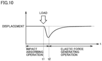
- Fig. 10 is a view illustrating processing for preventing the generation of the impact force due to contact between objects using actuator 2 of the embodiment.
- actuator 2 when the impact absorbing operation is previously executed to apply some load, actuator 2 operates passively according to the applied load. Thereafter, the operation is switched to the elastic force generating operation under a predetermined switching condition, and the load calculated based on the spring constant defined by the generated displacement and pattern is generated.
- actuator 2 In the impact absorbing operation, actuator 2 is not displaced at all unless the external force (external load) is applied.
- the external force external load
- the parameter corresponding to the applied external force is calculated, and the displacement of actuator 2 is controlled by the physical model having the calculated parameter.
- the switching condition switching between the impact absorbing operation and the elastic force generating operation may be based on the elapsed time after the load is applied to actuator 2 from the outside, the displacement (current position) generated in actuator 2, a trigger from the external device, or the like.
- Fig. 11 is a schematic diagram illustrating the main functional configuration implementing the impact absorbing operation and the elastic force generating operation by actuator 2 of the embodiment.
- controller 40 includes physical model 420, characteristic estimating unit 422, angular frequency setting unit 424, position instruction generating unit 426, load instruction generating unit 428, spring constant changing unit 430, displacement calculating unit 432, and a selecting unit 434.
- the functional configuration in Fig. 11 corresponds to addition of selecting unit 434 after a combination of the functional configuration implementing the impact absorbing operation in Fig. 7 and the functional configuration implementing the elastic force generating operation in Fig. 9 . That is, selecting unit 434 selects one of the control instruction implementing the impact absorbing operation output from position instruction generating unit 426 and the control instruction implementing the elastic force generating operation output from load instruction generating unit 428 to be validated.
- Selecting unit 434 has a switching condition 436, and selects and outputs one of the control instruction output from position instruction generating unit 426 and the control instruction output from load instruction generating unit 428 based on whether switching condition 436 is satisfied. Typically, selecting unit 434 validates the control instruction from load instruction generating unit 428 when switching condition 436 is satisfied while the control instruction from position instruction generating unit 426 is validated.
- Fig. 12 is a flowchart illustrating an example of a processing procedure related to the impact absorbing operation and the elastic force generating operation by actuator 2 of the embodiment.
- processor 402 of controller 40 executes control program 412 to implement each step in Fig. 12 .
- control program 412 a library or the like provided by system program 410 may be used as a part of the processing.
- steps S2 to S 14 correspond to processing related to the impact absorbing operation
- steps S20 to S28 correspond to processing related to the elastic force generating operation.
- controller 40 first performs the processing related to the impact absorbing operation. More specifically, controller 40 determines whether the load exceeding a predetermined value is applied to actuator 2 based on the detection signal from encoder 20 (step S2). When the load exceeding the predetermined value is not applied to actuator 2 (NO in step S2), the pieces of processing from step S2 are repeated.
- controller 40 calculates the speed of actuator 2 based on the detection signal by encoder 20 (step S4), and estimates the parameter of the physical model based on the calculated speed (step S6). Then, controller 40 creates the physical model including the estimated parameter (step S8). In this manner, controller 40 creates the physical model based on the displacement caused by the application of the load from the outside to actuator 2.
- Controller 40 inputs the elapsed time after the load exceeding the predetermined value is applied to actuator 2 to the physical model, calculates the control instruction (the position instruction or the displacement instruction) in the current control period (step S10), and outputs the calculated control instruction to driver 42 (step S12). That is, controller 40 controls motor 18 such that actuator 2 generates the displacement according to the physical model.
- controller 40 determines whether the condition switching to the elastic force generating operation (switching condition 436) is satisfied (step S14). When the condition switching to the elastic force generating operation is not satisfied (NO in step S14), the pieces of processing from step S10 are repeated.
- controller 40 When the condition switching to the elastic force generating operation is satisfied (YES in step S14), controller 40 performs the processing related to the following elastic force generating operation. More specifically, controller 40 determines spring constant K in the current control period with reference to the previously-set pattern (step S20). In this manner, controller 40 determines spring constant K.
- controller 40 acquires the current displacement of actuator 2 (step S22), and calculates the load to be generated by actuator 2 based on spring constant K and the current displacement of actuator 2 (step S24). Then, controller 40 calculates the control instruction (the position instruction or the displacement instruction) corresponding to the load to be generated (step S26), and outputs the calculated control instruction to driver 42 (step S28). In this manner, controller 40 controls motor 18 so as to generate drive force calculated based on the product of spring constant K and displacement ⁇ X generated in actuator 2.
- controller 40 switches the control of motor 18 so as to generate the drive force calculated based on the product of spring constant K and displacement ⁇ X generated in actuator 2.
- controller 40 determines whether an end condition of the elastic force generating operation is satisfied (step S30). When the end condition of the elastic force generating operation is not satisfied (NO in step S30), the pieces of processing from step S20 are repeated.
- step S30 When the end condition of the elastic force generating operation is satisfied (YES in step S30), the processing ends.
- FIG. 12 illustrates the processing example in which the impact absorbing operation and the elastic force generating operation by actuator 2 of the embodiment are combined, only the impact absorbing operation and only the elastic force generating operation may be performed. An appropriate operation is selected according to the application using actuator 2.
- Fig. 13 is a schematic view illustrating an example of a stage mechanism with one degree of freedom including the plurality of actuators 2 of the embodiment.
- Figs. 13(A) and 13(B) illustrate a configuration example of the stage mechanism in which plate 114 is supported by three actuators 2-1, 2-2, 2-3.
- the plurality of actuators 2 are mechanically connected to plate 114 that is a common member.
- controller 40 synchronously controls actuators 2-1, 2-2, 2-3, so that the entire surface of plate 114 can be controlled. At this point, controller 40 generates the control instructions for the actuators 2-1, 2-2, 2-3 such that the target load is generated from plate 114 that is the common member.
- controllers 40-1, 40-2, 40-3 control actuators 2-1, 2-2, 2-3, respectively.
- Each of actuators 2-1, 2-2, 2-3 is independently controlled, so that the behavior corresponding to a local load can be performed even when the local load is applied to plate 114.
- Fig. 14 is a schematic diagram illustrating the main functional configuration implementing the elastic force generating operation by the stage mechanism in Fig. 13(A) .
- actuators 2-1, 2-2, 2-3 are driven by drivers 42-1, 42-2, 42-3, and the displacement is detected by encoders 20-1, 20-2, 20-3.
- Controller 40 includes load instruction generating units 428-1, 428-2, 428-3, spring constant changing units 430-1, 430-2, 430-3, and displacement calculating units 432-1, 432-2, 432-3 in order to control actuators 2-1, 2-2, 2-3.
- each spring constant is changed or updated is controlled among spring constant changing units 430-1, 430-2, 430-3.
- the spring constants may be gradually changed in synchronization, or the spring constants may be arbitrated so as to correct the variation in the displacement.
- the load generated by plate 114 can be controlled on the entire surface by adopting such the control logic.
- the physical models corresponding to the actuators are synchronized with each other, so that the load generated in plate 114 can be controlled on the entire surface.
- Fig. 15 is a schematic view illustrating an example of a multi-degree-of-freedom stage mechanism 110A including the plurality of actuators 2 of the embodiment.
- stage mechanism 110A is a Z ⁇ -stage having two degrees of freedom. More specifically, stage mechanism 110A includes a rotating member 118 configured to rotate in a ⁇ -axis direction and three actuators 2-1, 2-2, 2-3 extending in a Z-axis direction.
- stage mechanism 110A in Fig. 15 enables the use in various applications.
- actuator 2 of the embodiment can be used alone or as the stage incorporating actuator 2. Furthermore, actuator 2 can also be used as a manufacturing device including the stage.
- Fig. 16 is a schematic diagram illustrating an example of the application using actuator 2 of the embodiment.
- Fig. 16 illustrates the application superimposing the workpieces in order to paste a workpiece W1 and a workpiece W2.
- an assembly device 200 in which two workpieces are overlapped includes stage mechanism 110A, a conveyance mechanism 150, and controller 40.
- Workpiece W1 is disposed on plate 114 of stage mechanism 110A.
- Workpiece W2 superimposed on workpiece W1 is conveyed by conveyance mechanism 150 from above stage mechanism 110A.
- Controller 40 gives the control instruction to stage mechanism 110A to control stage mechanism 110A.
- Stage mechanism 110A includes one or the plurality of actuators 2 that are driven by motor 18 to generate the displacement in a first direction (Z-axis direction). Because the configuration of stage mechanism 110A has been described with reference to Fig. 15 , the detailed description will not be repeated.
- Conveyance mechanism 150 includes a support column 152 and a plate 154.
- Plate 154 is connected to support column 152 and is movable in the vertical direction of gravity by a drive mechanism (not illustrated).
- Adsorption holes are made on the surface of plate 154.
- Workpiece W2 is conveyed in the state of being adsorbed to the surface of plate 154 by an adsorption mechanism (not illustrated).
- controller 40 gives the control instruction to stage mechanism 110A such that workpiece W1 and workpiece W2 are parallel to each other according to workpiece W2 superimposed on workpiece W1.
- the parallel maintaining operation may be implemented by feedback control based on a detection signal by a sensor (not illustrated) provided in conveyance mechanism 150.
- a predetermined distance margin is provided between the workpieces such that workpiece W1 and workpiece W2 do not collide with each other by orientation adjustment.
- the control is performed to reduce the distance between workpiece W1 and workpiece W2, namely, to superimpose workpiece W2 on workpiece W1 ((2) a workpiece approaching operation).
- conveyance mechanism 150 brings workpiece W2 close to workpiece W1 and adjusts the displacement of actuators 2-1, 2-2, 2-3 of stage mechanism 110A to maintain workpiece W1 and workpiece W2 in parallel.
- controller 40 creates the physical model based on the displacement in actuator 2 caused by workpiece W2 contacting workpiece W1. Then, controller 40 generates the control instruction that causes actuator 2 to be displaced according to the physical model. As described above, when workpiece W2 comes into contact with workpiece W1 to apply the load to actuator 2, actuator 2 operates like the spring according to the physical model as described above. The excessive load and the point load caused by the contact between workpiece W1 and workpiece W2 can be avoided by the impact absorbing operation.
- the elastic force generating operation is started ((4) the elastic force generating operation). That is, the control instruction that generates the drive force calculated based on the product of spring constant K and displacement ⁇ X generated in actuator 2 is generated. Pressing force is generated between workpiece W1 and workpiece W2 by the elastic force generating operation, and the pasting of workpiece W1 and workpiece W2 is completed.
- Fig. 17 is a flowchart illustrating the processing procedure in assembly device 200 in Fig. 16 .
- processor 402 of controller 40 executes control program 412 to implement each step in Fig. 17 .
- control program 412 a library or the like provided by system program 410 may be used as a part of the processing.
- controller 40 when the processing start is instructed (YES in step S100), controller 40 outputs the instruction to dispose workpiece W1 on stage mechanism 110A and the instruction to adsorb workpiece W2 to conveyance mechanism 150 (step S102). Then, controller 40 outputs the instruction to bring workpiece W2 adsorbed by conveyance mechanism 150 close to workpiece W1 (step S104), and starts the parallel maintaining operation.
- controller 40 adjusts the displacement of actuators 2-1, 2-2, 2-3 of stage mechanism 110A such that workpiece W1 and workpiece W2 are parallel to each other based on inclination of workpiece W2 adsorbed by conveyance mechanism 150 (step S106). In this manner, controller 40 gives the control instruction to stage mechanism 110A such that workpiece W1 and workpiece W2 are parallel to each other according to workpiece W2 superimposed on workpiece W1.
- controller 40 determines whether the switching condition switching to the workpiece approach operation is satisfied based on a parallelism degree between workpiece W1 and workpiece W2 (step S108). When the switching condition is not satisfied (NO in step S108), the pieces of processing from step S106 are repeated.
- controller 40 adjusts the displacement of actuators 2-1, 2-2, 2-3 of stage mechanism 110A such that workpiece W1 and workpiece W2 are maintained in parallel (step S110). Then, controller 40 determines whether the switching condition switching to the impact absorbing operation is satisfied based on the distance between workpiece W1 and workpiece W2 (step S112). When the switching condition is not satisfied (NO in step S 112), the pieces of processing from step S 110 are repeated.
- controller 40 starts the impact absorbing operation (step S114).
- the pieces of processing according to steps S2 to S 14 in Fig. 12 are performed.
- controller 40 starts the elastic force generating operation (step S1 16).
- the pieces of processing according to steps S20 to S28 in Fig. 12 are performed.
- controller 40 When the superimposition of workpiece W1 and workpiece W2 is completed, controller 40 outputs the instruction to convey superimposed workpieces W1 and W2 to the next process (step S118). Thus, one processing is completed.
- the workpieces can be pressed with the surface pressure between the workpieces uniformed while the impact generated between the workpieces to reduce the damage generated on the workpieces.
- the generation of a defective product can be reduced and the workpiece of higher quality can be manufactured.
- control (impact absorbing operation and/or elastic force generating operation) of actuator 2 of the embodiment can be applied to any application including contact between the objects, such as conveyance, superimposition, bonding, and insertion.
- actuator 2 of the embodiment can also be applied to a spring mechanism such as vibration removal and vibration suppression, a tensioner, and the like alone.
- actuator 2 of the embodiment can be applied to a mechanism that generates an arbitrary load such as a press device alone.
- the actuator behaves according to the physical formula, so that the simulation for the creation of the control logic and the facility design can be easily performed. In addition, even in the case where the actual device is configured, the deviation from the previous design is reduced.
- Impedance control and admittance control exist as an example of a technique of controlling the load and the position.
- the impedance control is a technique of adjusting characteristic (softness) of the actuator so as to remain at the target position when the load is applied to the actuator in the state where the target position and the impedance are previously set. For this reason, the control absorbing the impact force as in the impact absorbing operation of the embodiment is not implemented, but rather, sometimes the larger impact force is generated. In addition, in the impedance control, because the target position is given, the generated load cannot be controlled unlike the elastic force generating operation of the embodiment.
- the admittance control when the load is applied to the actuator while the impedance is previously set, the operation speed (position in each control period) is controlled based on the impedance. Consequently, only the behavior based on the previously-set impedance can be performed, so that the behavior cannot be changed according to the impact force unlike the impact absorbing operation of the embodiment. In addition, because the admittance control determines the behavior when the load is applied to the actuator, the generated load cannot be controlled unlike the elastic force generating operation of the embodiment.
- the impact absorbing operation and the elastic force generating operation of the embodiment are completely different from the impedance control and the admittance control.
- the above embodiment includes the following technical ideas.
- a drive system comprising:
- controller further comprises a setting unit (424) configured to set an angular frequency of the physical model based on mass of an object (114) attached to the actuator.
- model creation unit is configured to create the physical model when a predetermined load is applied to the actuator from an outside.
- a control method for an actuator (2) that is driven by a motor (18) to generate displacement comprising:
Landscapes
- Engineering & Computer Science (AREA)
- Power Engineering (AREA)
- Physics & Mathematics (AREA)
- General Physics & Mathematics (AREA)
- Automation & Control Theory (AREA)
- Evolutionary Computation (AREA)
- Artificial Intelligence (AREA)
- Computer Vision & Pattern Recognition (AREA)
- Health & Medical Sciences (AREA)
- Medical Informatics (AREA)
- Software Systems (AREA)
- General Engineering & Computer Science (AREA)
- Mechanical Engineering (AREA)
- Control Of Position Or Direction (AREA)
- Connection Of Motors, Electrical Generators, Mechanical Devices, And The Like (AREA)
- Reciprocating, Oscillating Or Vibrating Motors (AREA)
- Linear Motors (AREA)
- Vibration Prevention Devices (AREA)
Applications Claiming Priority (2)
| Application Number | Priority Date | Filing Date | Title |
|---|---|---|---|
| JP2021004647A JP2022109383A (ja) | 2021-01-15 | 2021-01-15 | 駆動システム、制御方法および制御プログラム |
| PCT/JP2021/009179 WO2022153563A1 (fr) | 2021-01-15 | 2021-03-09 | Système d'entraînement, procédé de commande, et programme de commande |
Publications (1)
| Publication Number | Publication Date |
|---|---|
| EP4279764A1 true EP4279764A1 (fr) | 2023-11-22 |
Family
ID=82447081
Family Applications (1)
| Application Number | Title | Priority Date | Filing Date |
|---|---|---|---|
| EP21919456.0A Pending EP4279764A1 (fr) | 2021-01-15 | 2021-03-09 | Système d'entraînement, procédé de commande, et programme de commande |
Country Status (6)
| Country | Link |
|---|---|
| US (1) | US20240103459A1 (fr) |
| EP (1) | EP4279764A1 (fr) |
| JP (1) | JP2022109383A (fr) |
| KR (1) | KR20230110602A (fr) |
| CN (1) | CN116635645A (fr) |
| WO (1) | WO2022153563A1 (fr) |
Family Cites Families (6)
| Publication number | Priority date | Publication date | Assignee | Title |
|---|---|---|---|---|
| JP4421605B2 (ja) * | 2000-06-30 | 2010-02-24 | 独立行政法人科学技術振興機構 | 除振方法およびその装置 |
| US7654540B2 (en) | 2004-06-18 | 2010-02-02 | Bose Corporation | Electromechanical transducing |
| US7983813B2 (en) | 2004-10-29 | 2011-07-19 | Bose Corporation | Active suspending |
| US8360387B2 (en) | 2010-03-26 | 2013-01-29 | Bose Corporation | Actuator including mechanism for converting rotary motion to linear motion |
| JP5991188B2 (ja) * | 2012-12-19 | 2016-09-14 | Jfeエンジニアリング株式会社 | 荷役機械の振動抑制方法及び装置 |
| JP6495497B1 (ja) * | 2018-02-16 | 2019-04-03 | 東芝エレベータ株式会社 | アクティブ制振装置 |
-
2021
- 2021-01-15 JP JP2021004647A patent/JP2022109383A/ja active Pending
- 2021-03-09 US US18/270,271 patent/US20240103459A1/en active Pending
- 2021-03-09 EP EP21919456.0A patent/EP4279764A1/fr active Pending
- 2021-03-09 CN CN202180086743.3A patent/CN116635645A/zh active Pending
- 2021-03-09 WO PCT/JP2021/009179 patent/WO2022153563A1/fr active Application Filing
- 2021-03-09 KR KR1020237021335A patent/KR20230110602A/ko unknown
Also Published As
| Publication number | Publication date |
|---|---|
| WO2022153563A1 (fr) | 2022-07-21 |
| KR20230110602A (ko) | 2023-07-24 |
| CN116635645A (zh) | 2023-08-22 |
| US20240103459A1 (en) | 2024-03-28 |
| JP2022109383A (ja) | 2022-07-28 |
Similar Documents
| Publication | Publication Date | Title |
|---|---|---|
| US8706429B2 (en) | Sensor apparatus and robot apparatus | |
| Hobbelen et al. | System overview of bipedal robots flame and tulip: Tailor-made for limit cycle walking | |
| Albu-Schäffer et al. | Dynamic modelling and control of variable stiffness actuators | |
| Petit et al. | State feedback damping control for a multi dof variable stiffness robot arm | |
| US20040172165A1 (en) | Legged mobile robot | |
| KR101682949B1 (ko) | 손 외골격 구조를 위한 힘 제어 구동기 모듈 및 이를 이용한 손 외골격 시스템 | |
| WO2000057340A1 (fr) | Organe de commande conforme de type muscle non lineaire | |
| Yildirim et al. | An integrated design approach for a series elastic actuator: Stiffness formulation, fatigue analysis, thermal management | |
| CN107690376B (zh) | 一种振动调节方法、系统、装置及工业机器人 | |
| Lakatos et al. | Modal limit cycle control for variable stiffness actuated robots | |
| Cao et al. | Toward broad optimal output bandwidth dielectric elastomer actuators | |
| Haiya et al. | Tension control for tendon mechanisms by compensation of nonlinear spring characteristic equation error | |
| EP4279764A1 (fr) | Système d'entraînement, procédé de commande, et programme de commande | |
| EP4280431A1 (fr) | Système d'entraînement, procédé de commande et programme de commande | |
| EP4280430A1 (fr) | Système d'entraînement, procédé de commande, et programme de commande | |
| EP4280432A1 (fr) | Dispositif de fabrication, procédé de commande et programme de commande | |
| JP5616290B2 (ja) | 移動体の制御装置 | |
| Radkhah et al. | A study of the passive rebound behavior of bipedal robots with stiff and different types of elastic actuation | |
| Kang et al. | Vibration control of a planar parallel manipulator using piezoelectric actuators | |
| Tsumugiwa et al. | Development of mechanical-impedance-varying mechanism in admittance control | |
| KR101999057B1 (ko) | 직렬 탄성 액추에이터 및 이를 포함하는 제어기 | |
| JP2007198827A (ja) | モーションベースの荷重付与治具 | |
| CN114454166B (zh) | 一种机械臂阻抗控制方法及装置 | |
| JP2011220452A (ja) | 防振装置 | |
| Gu et al. | Combined discrete-distributed control of a single-link flexible manipulator using a Lyapunov approach |
Legal Events
| Date | Code | Title | Description |
|---|---|---|---|
| STAA | Information on the status of an ep patent application or granted ep patent |
Free format text: STATUS: THE INTERNATIONAL PUBLICATION HAS BEEN MADE |
|
| PUAI | Public reference made under article 153(3) epc to a published international application that has entered the european phase |
Free format text: ORIGINAL CODE: 0009012 |
|
| STAA | Information on the status of an ep patent application or granted ep patent |
Free format text: STATUS: REQUEST FOR EXAMINATION WAS MADE |
|
| 17P | Request for examination filed |
Effective date: 20230626 |
|
| AK | Designated contracting states |
Kind code of ref document: A1 Designated state(s): AL AT BE BG CH CY CZ DE DK EE ES FI FR GB GR HR HU IE IS IT LI LT LU LV MC MK MT NL NO PL PT RO RS SE SI SK SM TR |
|
| DAV | Request for validation of the european patent (deleted) | ||
| DAX | Request for extension of the european patent (deleted) |