EP4279702A1 - Ladder, step-portion and system for using in the process of manufacturing a rotor blade - Google Patents
Ladder, step-portion and system for using in the process of manufacturing a rotor blade Download PDFInfo
- Publication number
- EP4279702A1 EP4279702A1 EP22174338.8A EP22174338A EP4279702A1 EP 4279702 A1 EP4279702 A1 EP 4279702A1 EP 22174338 A EP22174338 A EP 22174338A EP 4279702 A1 EP4279702 A1 EP 4279702A1
- Authority
- EP
- European Patent Office
- Prior art keywords
- ladder
- rails
- rotor blade
- rail
- coupling
- Prior art date
- Legal status (The legal status is an assumption and is not a legal conclusion. Google has not performed a legal analysis and makes no representation as to the accuracy of the status listed.)
- Granted
Links
Images

Classifications
-
- E—FIXED CONSTRUCTIONS
- E06—DOORS, WINDOWS, SHUTTERS, OR ROLLER BLINDS IN GENERAL; LADDERS
- E06C—LADDERS
- E06C1/00—Ladders in general
- E06C1/52—Ladders in general with non-rigid longitudinal members
-
- E—FIXED CONSTRUCTIONS
- E06—DOORS, WINDOWS, SHUTTERS, OR ROLLER BLINDS IN GENERAL; LADDERS
- E06C—LADDERS
- E06C1/00—Ladders in general
- E06C1/02—Ladders in general with rigid longitudinal member or members
- E06C1/04—Ladders for resting against objects, e.g. walls poles, trees
- E06C1/08—Ladders for resting against objects, e.g. walls poles, trees multi-part
- E06C1/10—Sections fitted end to end
-
- E—FIXED CONSTRUCTIONS
- E06—DOORS, WINDOWS, SHUTTERS, OR ROLLER BLINDS IN GENERAL; LADDERS
- E06C—LADDERS
- E06C1/00—Ladders in general
- E06C1/02—Ladders in general with rigid longitudinal member or members
- E06C1/04—Ladders for resting against objects, e.g. walls poles, trees
- E06C1/08—Ladders for resting against objects, e.g. walls poles, trees multi-part
-
- E—FIXED CONSTRUCTIONS
- E06—DOORS, WINDOWS, SHUTTERS, OR ROLLER BLINDS IN GENERAL; LADDERS
- E06C—LADDERS
- E06C1/00—Ladders in general
- E06C1/02—Ladders in general with rigid longitudinal member or members
- E06C1/38—Special constructions of ladders, e.g. ladders with more or less than two longitudinal members, ladders with movable rungs or other treads, longitudinally-foldable ladders
-
- E—FIXED CONSTRUCTIONS
- E06—DOORS, WINDOWS, SHUTTERS, OR ROLLER BLINDS IN GENERAL; LADDERS
- E06C—LADDERS
- E06C7/00—Component parts, supporting parts, or accessories
- E06C7/08—Special construction of longitudinal members, or rungs or other treads
-
- E—FIXED CONSTRUCTIONS
- E06—DOORS, WINDOWS, SHUTTERS, OR ROLLER BLINDS IN GENERAL; LADDERS
- E06C—LADDERS
- E06C7/00—Component parts, supporting parts, or accessories
- E06C7/08—Special construction of longitudinal members, or rungs or other treads
- E06C7/082—Connections between rungs or treads and longitudinal members
-
- E—FIXED CONSTRUCTIONS
- E06—DOORS, WINDOWS, SHUTTERS, OR ROLLER BLINDS IN GENERAL; LADDERS
- E06C—LADDERS
- E06C7/00—Component parts, supporting parts, or accessories
- E06C7/42—Ladder feet; Supports therefor
-
- E—FIXED CONSTRUCTIONS
- E06—DOORS, WINDOWS, SHUTTERS, OR ROLLER BLINDS IN GENERAL; LADDERS
- E06C—LADDERS
- E06C7/00—Component parts, supporting parts, or accessories
- E06C7/42—Ladder feet; Supports therefor
- E06C7/46—Non-skid equipment
-
- E—FIXED CONSTRUCTIONS
- E06—DOORS, WINDOWS, SHUTTERS, OR ROLLER BLINDS IN GENERAL; LADDERS
- E06C—LADDERS
- E06C9/00—Ladders characterised by being permanently attached to fixed structures, e.g. fire escapes
- E06C9/06—Ladders characterised by being permanently attached to fixed structures, e.g. fire escapes movably mounted
- E06C9/08—Ladders characterised by being permanently attached to fixed structures, e.g. fire escapes movably mounted with rigid longitudinal members
- E06C9/12—Ladders characterised by being permanently attached to fixed structures, e.g. fire escapes movably mounted with rigid longitudinal members laterally displaceable
Definitions
- the present invention relates to a ladder for using in the process of manufacturing a rotor blade of a wind turbine by leaning the ladder against the rotor blade being manufactured and climbing thereon, comprising two rails and a plurality of rungs.
- the rotor blade and/or the semi-finished rotor blade comprises fragile fiber reinforced components, which provides a limited supporting structure. That is, in order to reach up to the desired working area, a conventional ladder cannot be used, because it could cause damage to the rotor blade by bringing too much load onto a small outer surface of the rotor blade.
- known ladders are constructed such that they follow the given geometry of the rotor blade in a certain distance from the rotor blade and incorporate a load distributing top end, taking up both the weight from the ladder as well as the weight of the operator using the ladder. If not following the geometry of the rotor blade, the operator is not within reach of the lay-up and can therefore not do what is intended. All of this ends up in a ladder being both heavy, with limited ability to be used flexible as the ladder only comes in one piece, even though the lay-up geometry differs a lot lengthwise and/or there being different types of rotor blades.
- Aforesaid object is achieved by the subject-matters of the claims.
- the object is achieved by a ladder according to claim 1, a step-portion according to claim 13 as well as a system according to claim 14 of the present application.
- Further features and details of the invention can be drawn from the dependent claims, the description and the figures.
- Features and details discussed with respect to the inventive ladder are also correlated with the inventive step-portion, the inventive system and the other way around.
- a ladder for using in the process of manufacturing a rotor blade of a wind turbine by leaning the ladder against the rotor blade being manufactured and climbing thereon.
- the ladder comprises two rails and a plurality of rungs.
- the rails comprise a solid structure elastically bendable by the weight of a person climbing thereon in order to align a bending radius of the rails, resulting from an elastic bending of the rails, to an outer radius of the rotor blade being manufactured.
- the inventive ladder can be considered as a rigid or basically rigid ladder, which, however, is constructed such that it will be elastically bent in a predetermined manner by the weight of a person and/or an operator climbing on the ladder.
- the ladder can be provided straight and/or slightly pre-curved when not subjected to a load and flexes and/or deforms elastically when subjected to a load like the weight of the person.
- an inventive ladder When leaning the inventive ladder against the rotor blade and/or the semi-finished rotor blade, there will be no gap between the ladder and the rotor blade. Thus, safety is improved as the operator will stay permanently in the harness with the safety line constantly attached. Further, an inventive ladder can be manufactured stiff and light enough to be manually handled. No crane is necessary for the placement and/or movement of the ladder at the rotor blade.
- the ladder also allows the operator to stay as close to the surface of the rotor blade as possible. Therefore, ergonomics and working range can be maximized. Due to the intended bending of the ladder in order to align with the outer radius of the rotor blade or any other large building component, the load of the ladder and the operator is distributed on a much bigger surface in comparison to conventional rigid ladders, thus reducing the risk of any dislocation or wrinkles at the rotor blade occurring underneath the ladder.
- the flexibility of the rails and/or the ladder can be adapted by choosing the appropriate dimensions of the rails and/or the appropriate material.
- the only challenge is to choose the right dimensions and material in order to obtain the desired flexibility for adapting the shape of the ladder onto the construction part to be manufactured as well as the desired stiffness for allowing handling of the ladder by one operator only.
- the ladder has a height and/or length of at least 2 m, at least 3 m or at least 4 m.
- the ladder has a length between 3 m and 6 m.
- the ladder can be made of metal like aluminum, plastic and/or a composite material.
- Each rail may comprise a plurality of rail bars and/or rail components.
- the rungs or at least part of the rungs may be made of aluminum.
- each rung may comprise a bent metal sheet, in particular aluminum sheet, with a thickness between 1 mm and 2 mm.
- each rail of a ladder comprises a rail bar extending in one piece over the entire length of the ladder.
- the latter comprises high durability, relatively high stiffness and still the required flexibility when choosing appropriate dimensions and/or materials.
- Providing each rail bar in one piece means that each rail bar can be provided in one solid and/or monolithic piece.
- a ladder may comprise a cushion underneath and/or at the rails and/or the rungs for contacting the rotor blade when using the ladder for the process of manufacturing the rotor blade.
- the cushion can be plate-shaped and/or pad-shaped. That is, the cushion may not only be provided directly at the rails and/or the rungs, but also project and/or extend over the structure of the rails and/or the rungs.
- the cushion may be provided in one piece or may provide a plurality of pieces, which or a part of which can be located next to each other and/or spaced from each other.
- a plurality of cushion parts can be provided overlapping, in particular stepwise overlapping, each other. In this way, a continuous cushion plane having a consistent thickness and/or height can be provided while still having the desired flexibility of the ladder.
- the cushion can be made of foam, rubber and/or any other elastically deformable material.
- the material of the cushion can be softer than the material of the rails and/or the rungs. When using rubber for the cushion, the cushion also prevents dislocation of the ladder due to friction towards the lay-up surface of the rotor blade.
- the cushion of an inventive ladder extends in a width direction between the rails from one rail to the other rail.
- the cushion may not only be provided directly at the rails and/or the rungs, but also in between them. That way, a reliable force distribution onto the rotor blade can be achieved when using the ladder.
- the cushion extends over the entire width of the ladder or at least almost over the entire width of the ladder, that is, preferably from one rail to the other rail.
- the cushion may even extend beyond each rail, that is, in the width direction, from outside one rail over the rail to the other rail and beyond said other rail.
- the cushion of a ladder according to the present invention extends in a length direction between the rungs. That is, the cushion may not only extend in the width direction over the rails but also in the length direction over the rungs and/or between the rungs. This also contributes to an improved force distribution from the ladder and/or the person on the ladder onto the rotor blade during the manufacturing process when the ladder leans against the rotor blade.
- a ladder according to a further embodiment of the present invention may comprise a plurality of step-portions, wherein each step-portion comprises one rung and at least part of the cushion, wherein the rung and the cushion of each step-portion build an integral and/or monolithic unit.
- Such step-portions may provide a modular basis for building up a ladder with a specific length and/or flexibility depending on the rotor blade and/or construction component to be manufactured. Further, in case one step and/or part of one step-portion is damaged, the damaged part can be easily replaced without the need of replacing the whole ladder.
- the rungs and the cushion can be made of the same material.
- both the rungs and the cushion can be made of relatively hard rubber and/or plastic with an anti-slip surface and/or coating.
- An inventive ladder may further comprise a plurality of step-portions, wherein each step-portion comprises one rung and a mounting-portion for detachably mounting the step-portion to the rails.
- the mounting-portion may further comprise a guiding-structure in which the rails are located and/or locatable for guiding each step-portion along the rails.
- the step-portions and/or rungs may be firmly bonded, for example, bolted, glued and/or welded to the rails.
- the rails may provide a counter-mounting-structure for mounting the step-portions to a predetermined position at the rails.
- the counter-mounting-structure may comprise holes for screwing the step-portions to the rails, for example.
- the mounting portion may further serve as connection points where upper and/or lower rail bars and/or rail bar sections can be attached.
- the sides of the step-portions may comprise hollow tubes that rail bars can be inserted and attached, respectively.
- a ladder may provide a plurality of spacer sleeves being located at the rails in pairs between the step-portions, for holding the step-portions in a predetermined distance from each other.
- the spacer sleeves can be used to locate the rungs in a predetermined and equal distance to each other. Even when cushions and/or cushion elements are big enough to be located directly next to each other while providing the desired distance between the rungs, the spacer sleeves could be used in order to prevent abbreviations and thus damage to the cushion elements.
- the spacer sleeves are preferably tube shaped and/or provided as a coat around the rail bars. Between each step-portion, a pair of spacer sleeves may be located at and/or around the rails.
- each rung of a ladder can be roof shaped.
- each rung can be saddle roof shaped. That is, each rung may have a triangular shape and/or a triangular cross-section. That way, the rungs provide a stable platform for the operator even in different bending angles of the rails and the ladder, respectively.
- the roof shaped rungs can provide a relatively large contact surface for the above-described cushion.
- Each roof shaped rung may comprise or be made of bent plates and/or sheets. The sheets may be made of metal like aluminum.
- the roof shaped rungs may also be provided as integral and/or monolithic plastic, composite and/or rubber components.
- the rails of an inventive ladder are made of a fiber reinforced composite.
- the rails can be made of glass-fiber and/or carbon-fiber. Having the rails made of a fiber reinforced composite, they can be provided durable, rigid enough and still elastically deformable in the desired manner over the length of the ladder.
- the rail of an inventive ladder comprises a rail bar being tube-shaped with an open end side for detachably connecting a further rail bar in order to lengthen the ladder.
- the inventive ladder can be adapted in length as needed.
- a system comprised of individual elements that can easily be disassembled and thus easily be stored away or transported without taking up much space can be provided.
- a mechanism can be provided that allows a rail bar to be extended in either direction with another rail bar and/or rail bar section.
- the rail bars are hollow at either or both ends of a certain length so that an intermediate element can be inserted into the cavity and function as an extender piece between two rail bars.
- one first rail bar end is hollow and provides an inner diameter
- another rail bar provides a rail bar end having an outer diameter being complementary to the inner diameter allowing this end to be inserted into the end of the first rail bar, thus providing a telescope mechanism for elongating the rails to a certain and/or desired extend.
- an inventive ladder comprises a base-portion at a lower end side of the rails having a coupling-structure for coupling the base-portion to a counter-coupling-structure at the ground to prevent slipping of the ladder on the ground.
- the coupling-structure can be shaped such that it will only provide the desired stability to the ladder in combination with the counter-coupling structure.
- the coupling-structure may provide a protrusion to be inserted into a corresponding recess of the counter-coupling-structure in order to provide the required stability of the ladder on the ground.
- the coupling-structure may comprise a plate- and/or sheet-shaped protrusion to be inserted into a slit- and/or groove-shaped counter-coupling-structure on the ground.
- a further aspect of the present invention relates to a step-portion, comprising one rung and a mounting-portion for detachably mounting the step-portion to the rails of a ladder as described above. Therefore, the inventive step-portion brings up the same advantages that have been discussed in detail with respect to the inventive ladder.
- a system comprising a ladder as described in detail above and the counter-coupling-structure on the ground, wherein the coupling-structure is coupled to the counter-coupling-structure.
- a platform of the system may be present along a lower blade mold, for example with a platform height that allows an operator to reach into the lower blade mold.
- a steel strip of the system can be mounted flush with the platform surface as a walking area.
- the strip can be fitted with a groove acting as a locking device for the ladder to prevent the ladder from tilting but allowing sideways sliding along the curved surface of the rotor blade.
- the counter-coupling-structure can be provided on the ground, above the ground and/or underground.
- the counter-coupling-structure may comprise a guiding rail for guiding the ladder parallel to the rotor blade.
- the guiding rail may be provided on the ground, above the ground and/or underground.
- the guiding rail may further provide a groove shaped to guide in the ground and/or underground, extending parallel to the rotor blade and the component to be manufactured, respectively.
- the coupling-structure and/or the counter-coupling-structure may comprise wheels and/or a bearing carriage for an easy shifting of the latter along the rotor blade.
- a ladder 10 is shown that is used in the process of manufacturing a rotor blade 11 of a wind turbine by leaning the ladder 10 against the rotor blade 11.
- a person 14 and/or operator is climbing on the ladder 10 for working on the rotor blade 11.
- the ladder 10 comprises two rails 12 and a plurality of saddle roof shaped rungs 13.
- the rails 12 are made of a fiber reinforced composite and comprise a solid structure elastically bendable by the weight of the person 14 climbing thereon in order to align a bending radius of the rails 12, resulting from an elastic bending of the rails 12, to an outer radius of the rotor blade 11 being manufactured.
- each rail 12 comprises a rail bar 15 extending in one piece over the entire length of the ladder 10.
- the ladder 10 of Fig. 1 further comprises a base-portion 20 at a lower end side of the rails 12 having a plate-shaped coupling-structure 21 for coupling the base-portion 20 to a counter-coupling-structure 22 at the ground 23 to prevent slipping of the ladder 10 on the ground 23.
- Fig. 1 shows a system 100, comprising the ladder 10 and the counter-coupling-structure 22 at the ground 23, wherein the coupling-structure 21 is coupled to the counter-coupling-structure 22.
- the counter-coupling-structure 22 comprises a guiding rail for guiding and shifting the ladder 10 parallel to the rotor blade 11.
- Fig. 1 further shows a platform 24, at which the rotor blade 11 is located and onto which the ladder 10 leans as well. The platform 24 prevents the ladder 10 from bending inwardly to the rotor blade 11 in the lower section of the ladder 10.
- Fig. 2 shows parts of the ladder 10 and the counter-coupling-structure 22 in more detail.
- the ladder 10 comprises a plurality of step-portions 17, wherein each step-portion 17 comprises one rung 13 and a mounting-portion 18 for detachably mounting the step-portion 17 to the rails 12.
- the mounting-portion 18 comprises a snapping-portion for snapping the rail bars 15 into the snapping-portion.
- each rail 12 comprises a rail bar 15 being tube-shaped with an open end side for detachably connecting a further rail bar 15 in order to lengthen the rails 12 and the ladder 10, respectively.
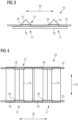
- Fig. 3 shows a side view of a ladder 10 according to a further embodiment.
- the ladder 10 comprises cushions 16 mounted underneath the rails 12 and the rungs 13 for contacting the rotor blade 11 when using the ladder 10 for the process of manufacturing the rotor blade 11.
- Each cushion 16 extends in a length direction 32 between the rungs 13, that is, as shown in Fig. 3 , in an area between the rungs 13.
- Fig. 4 shows a top view of the ladder 10 of Fig. 3 .
- each cushion 16 extends in a width direction 31 between the rails 12 from one rail 12 to the other rail 12 and slightly beyond the rails 12.
- the rung 13 and the cushion 16 of each step-portion 17 form an integral unit.
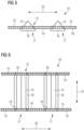
- Fig. 5 and Fig. 6 show a further embodiment of the ladder 10.
- the shown ladder comprises a plurality of spacer sleeves 19 being located at the rails 12 and around the rail bars 15 in pairs between the step-portions 17 for holding the step-portions 17 in a predetermined distance from each other.
Landscapes
- Engineering & Computer Science (AREA)
- Mechanical Engineering (AREA)
- Ladders (AREA)
Abstract
Description
- The present invention relates to a ladder for using in the process of manufacturing a rotor blade of a wind turbine by leaning the ladder against the rotor blade being manufactured and climbing thereon, comprising two rails and a plurality of rungs.
- During packing and/or inspection of large composite components like a wind turbine rotor blade, support structures are necessary in order to get access to upper parts of the components and the rotor blade, respectively. When manufacturing a rotor blade, the support structure will be used to reach to the upper sides and the top of the packing as part of the material lay-up process. The rotor blade and/or the semi-finished rotor blade comprises fragile fiber reinforced components, which provides a limited supporting structure. That is, in order to reach up to the desired working area, a conventional ladder cannot be used, because it could cause damage to the rotor blade by bringing too much load onto a small outer surface of the rotor blade.
- Therefore, known ladders are constructed such that they follow the given geometry of the rotor blade in a certain distance from the rotor blade and incorporate a load distributing top end, taking up both the weight from the ladder as well as the weight of the operator using the ladder. If not following the geometry of the rotor blade, the operator is not within reach of the lay-up and can therefore not do what is intended. All of this ends up in a ladder being both heavy, with limited ability to be used flexible as the ladder only comes in one piece, even though the lay-up geometry differs a lot lengthwise and/or there being different types of rotor blades. Depending on the location of the ladder along the blade, the distance between the ladder and the surface of the rotor blade is not constant and accordingly, certain areas may be difficult to reach for an operator. Consequently, safety may be compromised trying to do so. Hence, operator safety is ensured by using a harness for the operator and a safety line connected to an overhead crane.
- As a further problem, the weight of conventional ladders for the manufacturing process of rotor blades prevents any manual handling of the ladder. That is, a crane must be used. Consequently, the operator needs to climb down each time the ladder has to be relocated. This is both time consuming and tempting to work without a harness.
- It is an object of the present invention to overcome the above-mentioned problems. In particular, it is an object of the present invention to provide a system for facilitating the manual manufacturing process of large and fragile components like rotor blades for wind turbines.
- Aforesaid object is achieved by the subject-matters of the claims. In particular, the object is achieved by a ladder according to claim 1, a step-portion according to
claim 13 as well as a system according toclaim 14 of the present application. Further features and details of the invention can be drawn from the dependent claims, the description and the figures. Features and details discussed with respect to the inventive ladder are also correlated with the inventive step-portion, the inventive system and the other way around. - According to the present invention, a ladder is provided for using in the process of manufacturing a rotor blade of a wind turbine by leaning the ladder against the rotor blade being manufactured and climbing thereon. The ladder comprises two rails and a plurality of rungs. The rails comprise a solid structure elastically bendable by the weight of a person climbing thereon in order to align a bending radius of the rails, resulting from an elastic bending of the rails, to an outer radius of the rotor blade being manufactured.
- In the prior art, there are two types of ladders: rigid ladders that are self-supporting or that may be leaned against a vertical surface such as a wall, and rollable ladders, such as those made of rope or chains, that are meant to be hung. The inventive ladder can be considered as a rigid or basically rigid ladder, which, however, is constructed such that it will be elastically bent in a predetermined manner by the weight of a person and/or an operator climbing on the ladder. In other words, the ladder can be provided straight and/or slightly pre-curved when not subjected to a load and flexes and/or deforms elastically when subjected to a load like the weight of the person.
- When leaning the inventive ladder against the rotor blade and/or the semi-finished rotor blade, there will be no gap between the ladder and the rotor blade. Thus, safety is improved as the operator will stay permanently in the harness with the safety line constantly attached. Further, an inventive ladder can be manufactured stiff and light enough to be manually handled. No crane is necessary for the placement and/or movement of the ladder at the rotor blade.
- The ladder also allows the operator to stay as close to the surface of the rotor blade as possible. Therefore, ergonomics and working range can be maximized. Due to the intended bending of the ladder in order to align with the outer radius of the rotor blade or any other large building component, the load of the ladder and the operator is distributed on a much bigger surface in comparison to conventional rigid ladders, thus reducing the risk of any dislocation or wrinkles at the rotor blade occurring underneath the ladder.
- Depending on the use case for the ladder, the flexibility of the rails and/or the ladder can be adapted by choosing the appropriate dimensions of the rails and/or the appropriate material. In other words, having the inventive approach, the only challenge is to choose the right dimensions and material in order to obtain the desired flexibility for adapting the shape of the ladder onto the construction part to be manufactured as well as the desired stiffness for allowing handling of the ladder by one operator only.
- Preferably, the ladder has a height and/or length of at least 2 m, at least 3 m or at least 4 m. For example, the ladder has a length between 3 m and 6 m. By using proper material and dimensions, the total weight of the ladder can still be lower than 15 kg or even lower than 10 kg, depending on the length of the ladder. The ladder can be made of metal like aluminum, plastic and/or a composite material. Each rail may comprise a plurality of rail bars and/or rail components. The rungs or at least part of the rungs may be made of aluminum. For example, each rung may comprise a bent metal sheet, in particular aluminum sheet, with a thickness between 1 mm and 2 mm.
- According to a further embodiment of the present invention, it is possible that each rail of a ladder comprises a rail bar extending in one piece over the entire length of the ladder. When providing each rail bar in one piece, the latter comprises high durability, relatively high stiffness and still the required flexibility when choosing appropriate dimensions and/or materials. Providing each rail bar in one piece means that each rail bar can be provided in one solid and/or monolithic piece.
- In another embodiment of the present invention, a ladder may comprise a cushion underneath and/or at the rails and/or the rungs for contacting the rotor blade when using the ladder for the process of manufacturing the rotor blade. By means of the cushion, damage to the rotor blade and/or the component can be prevented during manufacturing. The cushion can be plate-shaped and/or pad-shaped. That is, the cushion may not only be provided directly at the rails and/or the rungs, but also project and/or extend over the structure of the rails and/or the rungs. The cushion may be provided in one piece or may provide a plurality of pieces, which or a part of which can be located next to each other and/or spaced from each other. A plurality of cushion parts can be provided overlapping, in particular stepwise overlapping, each other. In this way, a continuous cushion plane having a consistent thickness and/or height can be provided while still having the desired flexibility of the ladder. The cushion can be made of foam, rubber and/or any other elastically deformable material. The material of the cushion can be softer than the material of the rails and/or the rungs. When using rubber for the cushion, the cushion also prevents dislocation of the ladder due to friction towards the lay-up surface of the rotor blade.
- Furthermore, it is possible that the cushion of an inventive ladder extends in a width direction between the rails from one rail to the other rail. As already mentioned, the cushion may not only be provided directly at the rails and/or the rungs, but also in between them. That way, a reliable force distribution onto the rotor blade can be achieved when using the ladder. It is preferred that the cushion extends over the entire width of the ladder or at least almost over the entire width of the ladder, that is, preferably from one rail to the other rail. The cushion may even extend beyond each rail, that is, in the width direction, from outside one rail over the rail to the other rail and beyond said other rail.
- Moreover, it is possible that the cushion of a ladder according to the present invention extends in a length direction between the rungs. That is, the cushion may not only extend in the width direction over the rails but also in the length direction over the rungs and/or between the rungs. This also contributes to an improved force distribution from the ladder and/or the person on the ladder onto the rotor blade during the manufacturing process when the ladder leans against the rotor blade.
- A ladder according to a further embodiment of the present invention may comprise a plurality of step-portions, wherein each step-portion comprises one rung and at least part of the cushion, wherein the rung and the cushion of each step-portion build an integral and/or monolithic unit. Such step-portions may provide a modular basis for building up a ladder with a specific length and/or flexibility depending on the rotor blade and/or construction component to be manufactured. Further, in case one step and/or part of one step-portion is damaged, the damaged part can be easily replaced without the need of replacing the whole ladder. In a preferred embodiment, the rungs and the cushion can be made of the same material. For example, both the rungs and the cushion can be made of relatively hard rubber and/or plastic with an anti-slip surface and/or coating.
- An inventive ladder may further comprise a plurality of step-portions, wherein each step-portion comprises one rung and a mounting-portion for detachably mounting the step-portion to the rails. This leads, in particular, to the advantage as already mentioned above, that damaged parts can be easily replaced without the need of replacing the whole ladder in case one step and/or part of one step-portion is damaged. Further, having a specific mounting portion, building an inventive ladder by means of a plurality of step-portions and the rails can be easily realized. The mounting portion may comprise a resting-, clicking-, and/or snapping-structure for mounting the rails and/or the rail bars to the step-portion. That is, having the snapping-structure, for example, the rails and/or rail bars can be easily snapped into the snapping-portion when building the ladder. The mounting-portion may further comprise a guiding-structure in which the rails are located and/or locatable for guiding each step-portion along the rails. Alternatively, the step-portions and/or rungs may be firmly bonded, for example, bolted, glued and/or welded to the rails. The rails may provide a counter-mounting-structure for mounting the step-portions to a predetermined position at the rails. The counter-mounting-structure may comprise holes for screwing the step-portions to the rails, for example. Hence, an equal distance between the step-portions can be easily achieved when building the ladder. The mounting portion may further serve as connection points where upper and/or lower rail bars and/or rail bar sections can be attached. For example, the sides of the step-portions may comprise hollow tubes that rail bars can be inserted and attached, respectively.
- According to a further embodiment of the present invention, a ladder may provide a plurality of spacer sleeves being located at the rails in pairs between the step-portions, for holding the step-portions in a predetermined distance from each other. In particular, when the above-mentioned plurality of cushions is not located next to each other, the spacer sleeves can be used to locate the rungs in a predetermined and equal distance to each other. Even when cushions and/or cushion elements are big enough to be located directly next to each other while providing the desired distance between the rungs, the spacer sleeves could be used in order to prevent abbreviations and thus damage to the cushion elements. The spacer sleeves are preferably tube shaped and/or provided as a coat around the rail bars. Between each step-portion, a pair of spacer sleeves may be located at and/or around the rails.
- In accordance with another embodiment of the present invention, each rung of a ladder can be roof shaped. In particular, each rung can be saddle roof shaped. That is, each rung may have a triangular shape and/or a triangular cross-section. That way, the rungs provide a stable platform for the operator even in different bending angles of the rails and the ladder, respectively. Further, the roof shaped rungs can provide a relatively large contact surface for the above-described cushion. Each roof shaped rung may comprise or be made of bent plates and/or sheets. The sheets may be made of metal like aluminum. The roof shaped rungs may also be provided as integral and/or monolithic plastic, composite and/or rubber components.
- In addition, it is preferred that the rails of an inventive ladder are made of a fiber reinforced composite. For example, the rails can be made of glass-fiber and/or carbon-fiber. Having the rails made of a fiber reinforced composite, they can be provided durable, rigid enough and still elastically deformable in the desired manner over the length of the ladder.
- Moreover, it is possible that the rail of an inventive ladder comprises a rail bar being tube-shaped with an open end side for detachably connecting a further rail bar in order to lengthen the ladder. With the tube-shaped and open ended rail bars, the inventive ladder can be adapted in length as needed. Further, a system comprised of individual elements that can easily be disassembled and thus easily be stored away or transported without taking up much space can be provided. Further, a mechanism can be provided that allows a rail bar to be extended in either direction with another rail bar and/or rail bar section. Furthermore, the rail bars are hollow at either or both ends of a certain length so that an intermediate element can be inserted into the cavity and function as an extender piece between two rail bars.
- In another variant, one first rail bar end is hollow and provides an inner diameter, while another rail bar provides a rail bar end having an outer diameter being complementary to the inner diameter allowing this end to be inserted into the end of the first rail bar, thus providing a telescope mechanism for elongating the rails to a certain and/or desired extend.
- It is also possible that an inventive ladder comprises a base-portion at a lower end side of the rails having a coupling-structure for coupling the base-portion to a counter-coupling-structure at the ground to prevent slipping of the ladder on the ground. With the coupling structure, the ladder can be used safely with only the operator on the ladder, i.e., no further person on the ground. The coupling-structure can be shaped such that it will only provide the desired stability to the ladder in combination with the counter-coupling structure. For example, the coupling-structure may provide a protrusion to be inserted into a corresponding recess of the counter-coupling-structure in order to provide the required stability of the ladder on the ground. For example, the coupling-structure may comprise a plate- and/or sheet-shaped protrusion to be inserted into a slit- and/or groove-shaped counter-coupling-structure on the ground.
- A further aspect of the present invention relates to a step-portion, comprising one rung and a mounting-portion for detachably mounting the step-portion to the rails of a ladder as described above. Therefore, the inventive step-portion brings up the same advantages that have been discussed in detail with respect to the inventive ladder.
- Another aspect of the invention relates to a system comprising a ladder as described in detail above and the counter-coupling-structure on the ground, wherein the coupling-structure is coupled to the counter-coupling-structure. Such a system also provides the above-described advantages. When packing a topside of the rotor blade, a platform of the system may be present along a lower blade mold, for example with a platform height that allows an operator to reach into the lower blade mold. On such a platform, a steel strip of the system can be mounted flush with the platform surface as a walking area. The strip can be fitted with a groove acting as a locking device for the ladder to prevent the ladder from tilting but allowing sideways sliding along the curved surface of the rotor blade. The counter-coupling-structure can be provided on the ground, above the ground and/or underground.
- In an inventive system, the counter-coupling-structure may comprise a guiding rail for guiding the ladder parallel to the rotor blade. With the guiding rail, the ladder can be shifted easily and safely along the rotor blade by one person only. The guiding rail may be provided on the ground, above the ground and/or underground. In case the guiding rail is provided underground, the guiding rail may further provide a groove shaped to guide in the ground and/or underground, extending parallel to the rotor blade and the component to be manufactured, respectively. The coupling-structure and/or the counter-coupling-structure may comprise wheels and/or a bearing carriage for an easy shifting of the latter along the rotor blade.
- Further measures improving the inventive concept can be drawn from the following description of preferred embodiments, which are schematically shown in the drawings. The features and advantages which can be drawn from the claims, from the description and from the drawings, might be considered essential alone or in combination with each other.
- The present invention is discussed in more detail with respect to the accompanying drawings, in which
- Fig. 1
- shows a side view of a system according to a preferred embodiment of the present invention,
- Fig. 2
- shows a perspective view of a ladder according to a preferred embodiment of the present invention,
- Fig. 3
- shows a side view of a ladder according to a further embodiment of the present invention,
- Fig. 4
- shows a top view of a ladder according to the embodiment of
Fig. 3 , - Fig. 5
- shows a side view of a ladder according to a further embodiment of the present invention, and
- Fig. 6
- shows a top view of a ladder according to the embodiment of
Fig. 5 . - Elements and features having the same function and operating principle are labeled with the same reference signs in the drawings.
- In
Fig. 1 , aladder 10 is shown that is used in the process of manufacturing arotor blade 11 of a wind turbine by leaning theladder 10 against therotor blade 11. As shown inFig. 1 , aperson 14 and/or operator is climbing on theladder 10 for working on therotor blade 11. Theladder 10 comprises tworails 12 and a plurality of saddle roof shapedrungs 13. Therails 12 are made of a fiber reinforced composite and comprise a solid structure elastically bendable by the weight of theperson 14 climbing thereon in order to align a bending radius of therails 12, resulting from an elastic bending of therails 12, to an outer radius of therotor blade 11 being manufactured. According to the embodiment shown inFig. 1 , eachrail 12 comprises arail bar 15 extending in one piece over the entire length of theladder 10. - The
ladder 10 ofFig. 1 further comprises a base-portion 20 at a lower end side of therails 12 having a plate-shaped coupling-structure 21 for coupling the base-portion 20 to a counter-coupling-structure 22 at theground 23 to prevent slipping of theladder 10 on theground 23. In particular,Fig. 1 shows asystem 100, comprising theladder 10 and the counter-coupling-structure 22 at theground 23, wherein the coupling-structure 21 is coupled to the counter-coupling-structure 22. In accordance with the embodiment ofFig. 1 , the counter-coupling-structure 22 comprises a guiding rail for guiding and shifting theladder 10 parallel to therotor blade 11.Fig. 1 further shows aplatform 24, at which therotor blade 11 is located and onto which theladder 10 leans as well. Theplatform 24 prevents theladder 10 from bending inwardly to therotor blade 11 in the lower section of theladder 10. -
Fig. 2 shows parts of theladder 10 and the counter-coupling-structure 22 in more detail. As can be further drawn fromFig. 2 , theladder 10 comprises a plurality of step-portions 17, wherein each step-portion 17 comprises onerung 13 and a mounting-portion 18 for detachably mounting the step-portion 17 to therails 12. According to the embodiment ofFig. 2 , the mounting-portion 18 comprises a snapping-portion for snapping the rail bars 15 into the snapping-portion. In the embodiment ofFig. 2 , eachrail 12 comprises arail bar 15 being tube-shaped with an open end side for detachably connecting afurther rail bar 15 in order to lengthen therails 12 and theladder 10, respectively. -
Fig. 3 shows a side view of aladder 10 according to a further embodiment. As shown inFig. 3 , theladder 10 comprisescushions 16 mounted underneath therails 12 and therungs 13 for contacting therotor blade 11 when using theladder 10 for the process of manufacturing therotor blade 11. Eachcushion 16 extends in alength direction 32 between therungs 13, that is, as shown inFig. 3 , in an area between the rungs 13. -
Fig. 4 shows a top view of theladder 10 ofFig. 3 . As can be seen there, eachcushion 16 extends in awidth direction 31 between therails 12 from onerail 12 to theother rail 12 and slightly beyond therails 12. Therung 13 and thecushion 16 of each step-portion 17 form an integral unit. -
Fig. 5 and Fig. 6 show a further embodiment of theladder 10. The shown ladder comprises a plurality ofspacer sleeves 19 being located at therails 12 and around the rail bars 15 in pairs between the step-portions 17 for holding the step-portions 17 in a predetermined distance from each other. - The aforesaid description of the accompanying drawings is only by the way of detail and example. Specific features of each aspect of the present invention and the figures can be combined which each other if of technical sense.
Claims (15)
- A ladder (10) for using in the process of manufacturing a rotor blade (11) by leaning the ladder (10) against the rotor blade (11) being manufactured and climbing thereon, comprising two rails (12) and a plurality of rungs (13),
characterized in that
the rails (12) comprise a solid structure elastically bendable by the weight of a person (14) climbing thereon in order to align a bending radius of the rails (12), resulting from an elastic bending of the rails (12), to an outer radius of the rotor blade (11) being manufactured. - The ladder (10) according to claim 1,
characterized in that
each rail (12) comprises a rail bar (15) extending in one piece over the entire length of the ladder (10). - The ladder (10) according to one of the above claims, characterized by
a cushion (16) underneath the rails (12) and/or the rungs (13) for contacting the rotor blade (11) when using the ladder (10) for the process of manufacturing the rotor blade (11). - The ladder (10) according to claim 3,
characterized in that
the cushion (16) extends in a width direction (31) between the rails (12) from one rail (12) to the other rail (12). - The ladder (10) according to one of claims 3 to 4, characterized in that
the cushion (16) extends in a length direction (32) between the rungs (13). - The ladder (10) according to one of claims 3 to 5, characterized by
a plurality of step-portions (17), wherein each step-portion (17) comprises one rung (13) and at least part of the cushion (16), wherein the rung (13) and the cushion (16) of each step-portion (17) build an integral and/or monolithic unit. - The ladder (10) according to one of the above claims, characterized by
a plurality of step-portions (17), wherein each step-portion (17) comprises one rung (13) and a mounting-portion (18) for detachably mounting the step-portion (17) to the rails (12). - The ladder (10) according to claim 7,
characterized by
a plurality of spacer sleeves (19) being located at the rails (12) in pairs between the step-portions (17) for holding the step-portions (17) in a predetermined distance from each other. - The ladder (10) according to one of the above claims, characterized in that
each rung (13) is roof shaped. - The ladder (10) according to one of the above claims, characterized in that
the rails (12) are made of a fiber reinforced composite. - The ladder (10) according to one of the above claims, characterized in that
each rail (12) comprises a rail bar (15) being tube-shaped with an open end side for detachably connecting a further rail bar (15) in order to lengthen the ladder (10). - The ladder (10) according to one of the above claims, characterized by
a base-portion (20) at a lower end side of the rails (12) having a coupling-structure (21) for coupling the base-portion (20) to a counter-coupling-structure (22) at the ground (23) to prevent slipping of the ladder (10) on the ground (23). - A step-portion (17), comprising one rung (13) and a mounting-portion (18) for detachably mounting the step-portion (17) to the rails (12) of a ladder (10) according to one of the above claims.
- A system (100), comprising a ladder (10) according to claim 12 and the counter-coupling-structure (22) at the ground (23), wherein the coupling-structure (21) is coupled to the counter-coupling-structure (22).
- The system (100) according to claim 14,
characterized in that
the counter-coupling-structure (22) comprises a guiding rail for guiding the ladder (10) parallel to the rotor blade (11).
Priority Applications (5)
| Application Number | Priority Date | Filing Date | Title |
|---|---|---|---|
| EP22174338.8A EP4279702B1 (en) | 2022-05-19 | 2022-05-19 | Ladder and system for using in the process of manufacturing a rotor blade |
| PL22174338.8T PL4279702T3 (en) | 2022-05-19 | 2022-05-19 | Ladder and system for using in the process of manufacturing a rotor blade |
| DK22174338.8T DK4279702T3 (en) | 2022-05-19 | 2022-05-19 | Ladder and system for using in the process of manufacturing a rotor blade |
| US18/142,069 US20230374856A1 (en) | 2022-05-19 | 2023-05-02 | Ladder, step-portion and system for using in the process of manufacturing a rotor blade |
| CN202310573921.6A CN117090500A (en) | 2022-05-19 | 2023-05-19 | Ladder, step portion and system for use in manufacturing rotor blades |
Applications Claiming Priority (1)
| Application Number | Priority Date | Filing Date | Title |
|---|---|---|---|
| EP22174338.8A EP4279702B1 (en) | 2022-05-19 | 2022-05-19 | Ladder and system for using in the process of manufacturing a rotor blade |
Publications (2)
| Publication Number | Publication Date |
|---|---|
| EP4279702A1 true EP4279702A1 (en) | 2023-11-22 |
| EP4279702B1 EP4279702B1 (en) | 2025-07-09 |
Family
ID=81749293
Family Applications (1)
| Application Number | Title | Priority Date | Filing Date |
|---|---|---|---|
| EP22174338.8A Active EP4279702B1 (en) | 2022-05-19 | 2022-05-19 | Ladder and system for using in the process of manufacturing a rotor blade |
Country Status (5)
| Country | Link |
|---|---|
| US (1) | US20230374856A1 (en) |
| EP (1) | EP4279702B1 (en) |
| CN (1) | CN117090500A (en) |
| DK (1) | DK4279702T3 (en) |
| PL (1) | PL4279702T3 (en) |
Citations (7)
| Publication number | Priority date | Publication date | Assignee | Title |
|---|---|---|---|---|
| JPS51150829U (en) * | 1975-05-26 | 1976-12-02 | ||
| US4917216A (en) * | 1988-06-16 | 1990-04-17 | Kimber Edward G | Segmented ladder construction |
| DE4216570A1 (en) * | 1992-05-20 | 1993-11-25 | Leifheit Ag | Step ladder of pluggable components - has both ends of each step with transverse apertures w.r.t. step tread face |
| JP2011214348A (en) * | 2010-04-01 | 2011-10-27 | Bridgestone Corp | Ladder |
| US20150336334A1 (en) * | 2012-12-31 | 2015-11-26 | Vestas Wind Systems A/S | Device for accessing the sides of a wind turbine blade mould |
| US20190218860A1 (en) * | 2016-05-07 | 2019-07-18 | Jls Painting, Llc | Ladder bumper |
| JP6966136B1 (en) * | 2021-05-29 | 2021-11-10 | 株式会社スペース二十四インフォメーション | Scaffolding structure that holds the ladder three-dimensionally movable |
Family Cites Families (6)
| Publication number | Priority date | Publication date | Assignee | Title |
|---|---|---|---|---|
| US2708543A (en) * | 1953-07-13 | 1955-05-17 | Matich John | Rubber grip roof ladder |
| FR2388124A1 (en) * | 1977-04-22 | 1978-11-17 | Sidec Sa Ste Indle Chassant | Foldable ladder for inclined roof - has flexible carpet provided with integral triangular section rubber rungs |
| FR2623560B1 (en) * | 1987-11-19 | 1990-03-09 | Mariot Jacques | FLEXIBLE LADDER WITH MAGNETIC HANGING |
| US5203427A (en) * | 1992-05-15 | 1993-04-20 | Williams Sr Anthony E | Fire escape ladder with integral air cushion |
| US6006863A (en) * | 1999-06-28 | 1999-12-28 | Legrand; Pamela | Ladder leg protection |
| US20060243525A1 (en) * | 2005-04-25 | 2006-11-02 | Brett Bengston | Ladder cushion |
-
2022
- 2022-05-19 EP EP22174338.8A patent/EP4279702B1/en active Active
- 2022-05-19 DK DK22174338.8T patent/DK4279702T3/en active
- 2022-05-19 PL PL22174338.8T patent/PL4279702T3/en unknown
-
2023
- 2023-05-02 US US18/142,069 patent/US20230374856A1/en active Pending
- 2023-05-19 CN CN202310573921.6A patent/CN117090500A/en active Pending
Patent Citations (7)
| Publication number | Priority date | Publication date | Assignee | Title |
|---|---|---|---|---|
| JPS51150829U (en) * | 1975-05-26 | 1976-12-02 | ||
| US4917216A (en) * | 1988-06-16 | 1990-04-17 | Kimber Edward G | Segmented ladder construction |
| DE4216570A1 (en) * | 1992-05-20 | 1993-11-25 | Leifheit Ag | Step ladder of pluggable components - has both ends of each step with transverse apertures w.r.t. step tread face |
| JP2011214348A (en) * | 2010-04-01 | 2011-10-27 | Bridgestone Corp | Ladder |
| US20150336334A1 (en) * | 2012-12-31 | 2015-11-26 | Vestas Wind Systems A/S | Device for accessing the sides of a wind turbine blade mould |
| US20190218860A1 (en) * | 2016-05-07 | 2019-07-18 | Jls Painting, Llc | Ladder bumper |
| JP6966136B1 (en) * | 2021-05-29 | 2021-11-10 | 株式会社スペース二十四インフォメーション | Scaffolding structure that holds the ladder three-dimensionally movable |
Also Published As
| Publication number | Publication date |
|---|---|
| EP4279702B1 (en) | 2025-07-09 |
| DK4279702T3 (en) | 2025-09-15 |
| US20230374856A1 (en) | 2023-11-23 |
| PL4279702T3 (en) | 2025-11-03 |
| CN117090500A (en) | 2023-11-21 |
Similar Documents
| Publication | Publication Date | Title |
|---|---|---|
| US4941547A (en) | Safety featured ladder scaffolding | |
| EP3221519B1 (en) | Scaffolding arrangement | |
| US4825976A (en) | Scaffolding platform | |
| US20100122872A1 (en) | Scaffold elevator | |
| EP1989374B1 (en) | Plastic platform for a foldable ladder and combination of a plastic platform and foldable ladder | |
| EP4279702B1 (en) | Ladder and system for using in the process of manufacturing a rotor blade | |
| MX2014000733A (en) | Component having a fastening apparatus for add-on parts. | |
| WO2006024832A1 (en) | A ladder for a manhole | |
| ATE239158T1 (en) | FORMWORK DEVICE IN COMPOSITE MATERIAL | |
| US3374861A (en) | Scaffolding platform | |
| EP1696084A1 (en) | Telescopic rail for use in forming a guard or safety barrier for builders' trestles | |
| EP1694930A1 (en) | Extensible, self locking platform and method of using same | |
| KR100960071B1 (en) | Roof sheet fixing frame of the structure having a roof and roof sheet fixing method using the frame | |
| US5152371A (en) | Lightweight scaffolding | |
| US20190078339A1 (en) | Adjustable roofing scaffold system and method of use | |
| JP7051642B2 (en) | Mobile lift scaffolding | |
| DK2938803T3 (en) | PROCEDURE FOR PREPARING A WINDMILL BLADE | |
| CN216865923U (en) | Outer wall decoration operation platform capable of moving horizontally | |
| EP1245755A1 (en) | Tower assembly | |
| EP1691007A2 (en) | Detachable cross-piece for supporting platforms in scaffolds | |
| JP7799317B2 (en) | Assembled temporary stairs | |
| AU2021107218A4 (en) | Ladder platform system | |
| KR102640943B1 (en) | CFRP bonded ladder for agricultural machinery | |
| US12312215B2 (en) | System for lifting a wind turbine rotor blade | |
| KR20230003790A (en) | CFRP bonded ladder |
Legal Events
| Date | Code | Title | Description |
|---|---|---|---|
| PUAI | Public reference made under article 153(3) epc to a published international application that has entered the european phase |
Free format text: ORIGINAL CODE: 0009012 |
|
| STAA | Information on the status of an ep patent application or granted ep patent |
Free format text: STATUS: THE APPLICATION HAS BEEN PUBLISHED |
|
| AK | Designated contracting states |
Kind code of ref document: A1 Designated state(s): AL AT BE BG CH CY CZ DE DK EE ES FI FR GB GR HR HU IE IS IT LI LT LU LV MC MK MT NL NO PL PT RO RS SE SI SK SM TR |
|
| STAA | Information on the status of an ep patent application or granted ep patent |
Free format text: STATUS: REQUEST FOR EXAMINATION WAS MADE |
|
| 17P | Request for examination filed |
Effective date: 20240312 |
|
| RBV | Designated contracting states (corrected) |
Designated state(s): AL AT BE BG CH CY CZ DE DK EE ES FI FR GB GR HR HU IE IS IT LI LT LU LV MC MK MT NL NO PL PT RO RS SE SI SK SM TR |
|
| GRAP | Despatch of communication of intention to grant a patent |
Free format text: ORIGINAL CODE: EPIDOSNIGR1 |
|
| STAA | Information on the status of an ep patent application or granted ep patent |
Free format text: STATUS: GRANT OF PATENT IS INTENDED |
|
| INTG | Intention to grant announced |
Effective date: 20240927 |
|
| GRAJ | Information related to disapproval of communication of intention to grant by the applicant or resumption of examination proceedings by the epo deleted |
Free format text: ORIGINAL CODE: EPIDOSDIGR1 |
|
| STAA | Information on the status of an ep patent application or granted ep patent |
Free format text: STATUS: REQUEST FOR EXAMINATION WAS MADE |
|
| GRAP | Despatch of communication of intention to grant a patent |
Free format text: ORIGINAL CODE: EPIDOSNIGR1 |
|
| STAA | Information on the status of an ep patent application or granted ep patent |
Free format text: STATUS: GRANT OF PATENT IS INTENDED |
|
| INTG | Intention to grant announced |
Effective date: 20250203 |
|
| GRAS | Grant fee paid |
Free format text: ORIGINAL CODE: EPIDOSNIGR3 |
|
| GRAA | (expected) grant |
Free format text: ORIGINAL CODE: 0009210 |
|
| STAA | Information on the status of an ep patent application or granted ep patent |
Free format text: STATUS: THE PATENT HAS BEEN GRANTED |
|
| AK | Designated contracting states |
Kind code of ref document: B1 Designated state(s): AL AT BE BG CH CY CZ DE DK EE ES FI FR GB GR HR HU IE IS IT LI LT LU LV MC MK MT NL NO PL PT RO RS SE SI SK SM TR |
|
| REG | Reference to a national code |
Ref country code: GB Ref legal event code: FG4D |
|
| REG | Reference to a national code |
Ref country code: CH Ref legal event code: EP |
|
| REG | Reference to a national code |
Ref country code: IE Ref legal event code: FG4D |
|
| REG | Reference to a national code |
Ref country code: DE Ref legal event code: R096 Ref document number: 602022017190 Country of ref document: DE |
|
| REG | Reference to a national code |
Ref country code: DK Ref legal event code: T3 Effective date: 20250912 |
|
| REG | Reference to a national code |
Ref country code: NL Ref legal event code: FP |
|
| PG25 | Lapsed in a contracting state [announced via postgrant information from national office to epo] |
Ref country code: PT Free format text: LAPSE BECAUSE OF FAILURE TO SUBMIT A TRANSLATION OF THE DESCRIPTION OR TO PAY THE FEE WITHIN THE PRESCRIBED TIME-LIMIT Effective date: 20251110 |
|
| REG | Reference to a national code |
Ref country code: AT Ref legal event code: MK05 Ref document number: 1811979 Country of ref document: AT Kind code of ref document: T Effective date: 20250709 |
|
| PG25 | Lapsed in a contracting state [announced via postgrant information from national office to epo] |
Ref country code: IS Free format text: LAPSE BECAUSE OF FAILURE TO SUBMIT A TRANSLATION OF THE DESCRIPTION OR TO PAY THE FEE WITHIN THE PRESCRIBED TIME-LIMIT Effective date: 20251109 |
|
| PG25 | Lapsed in a contracting state [announced via postgrant information from national office to epo] |
Ref country code: NO Free format text: LAPSE BECAUSE OF FAILURE TO SUBMIT A TRANSLATION OF THE DESCRIPTION OR TO PAY THE FEE WITHIN THE PRESCRIBED TIME-LIMIT Effective date: 20251009 |
|
| REG | Reference to a national code |
Ref country code: LT Ref legal event code: MG9D |
|
| PG25 | Lapsed in a contracting state [announced via postgrant information from national office to epo] |
Ref country code: AT Free format text: LAPSE BECAUSE OF FAILURE TO SUBMIT A TRANSLATION OF THE DESCRIPTION OR TO PAY THE FEE WITHIN THE PRESCRIBED TIME-LIMIT Effective date: 20250709 |
|
| PG25 | Lapsed in a contracting state [announced via postgrant information from national office to epo] |
Ref country code: FI Free format text: LAPSE BECAUSE OF FAILURE TO SUBMIT A TRANSLATION OF THE DESCRIPTION OR TO PAY THE FEE WITHIN THE PRESCRIBED TIME-LIMIT Effective date: 20250709 |
|
| PG25 | Lapsed in a contracting state [announced via postgrant information from national office to epo] |
Ref country code: HR Free format text: LAPSE BECAUSE OF FAILURE TO SUBMIT A TRANSLATION OF THE DESCRIPTION OR TO PAY THE FEE WITHIN THE PRESCRIBED TIME-LIMIT Effective date: 20250709 |
|
| PG25 | Lapsed in a contracting state [announced via postgrant information from national office to epo] |
Ref country code: GR Free format text: LAPSE BECAUSE OF FAILURE TO SUBMIT A TRANSLATION OF THE DESCRIPTION OR TO PAY THE FEE WITHIN THE PRESCRIBED TIME-LIMIT Effective date: 20251010 |
|
| PG25 | Lapsed in a contracting state [announced via postgrant information from national office to epo] |
Ref country code: SE Free format text: LAPSE BECAUSE OF FAILURE TO SUBMIT A TRANSLATION OF THE DESCRIPTION OR TO PAY THE FEE WITHIN THE PRESCRIBED TIME-LIMIT Effective date: 20250709 |
|
| PG25 | Lapsed in a contracting state [announced via postgrant information from national office to epo] |
Ref country code: LV Free format text: LAPSE BECAUSE OF FAILURE TO SUBMIT A TRANSLATION OF THE DESCRIPTION OR TO PAY THE FEE WITHIN THE PRESCRIBED TIME-LIMIT Effective date: 20250709 |
|
| PG25 | Lapsed in a contracting state [announced via postgrant information from national office to epo] |
Ref country code: BG Free format text: LAPSE BECAUSE OF FAILURE TO SUBMIT A TRANSLATION OF THE DESCRIPTION OR TO PAY THE FEE WITHIN THE PRESCRIBED TIME-LIMIT Effective date: 20250709 |
|
| PG25 | Lapsed in a contracting state [announced via postgrant information from national office to epo] |
Ref country code: RS Free format text: LAPSE BECAUSE OF FAILURE TO SUBMIT A TRANSLATION OF THE DESCRIPTION OR TO PAY THE FEE WITHIN THE PRESCRIBED TIME-LIMIT Effective date: 20251009 |
|
| PG25 | Lapsed in a contracting state [announced via postgrant information from national office to epo] |
Ref country code: ES Free format text: LAPSE BECAUSE OF FAILURE TO SUBMIT A TRANSLATION OF THE DESCRIPTION OR TO PAY THE FEE WITHIN THE PRESCRIBED TIME-LIMIT Effective date: 20250709 |
|
| PG25 | Lapsed in a contracting state [announced via postgrant information from national office to epo] |
Ref country code: SM Free format text: LAPSE BECAUSE OF FAILURE TO SUBMIT A TRANSLATION OF THE DESCRIPTION OR TO PAY THE FEE WITHIN THE PRESCRIBED TIME-LIMIT Effective date: 20250709 |
|
| PGFP | Annual fee paid to national office [announced via postgrant information from national office to epo] |
Ref country code: GB Payment date: 20260323 Year of fee payment: 5 |
|
| PG25 | Lapsed in a contracting state [announced via postgrant information from national office to epo] |
Ref country code: IT Free format text: LAPSE BECAUSE OF FAILURE TO SUBMIT A TRANSLATION OF THE DESCRIPTION OR TO PAY THE FEE WITHIN THE PRESCRIBED TIME-LIMIT Effective date: 20250709 |
|
| PG25 | Lapsed in a contracting state [announced via postgrant information from national office to epo] |
Ref country code: CZ Free format text: LAPSE BECAUSE OF FAILURE TO SUBMIT A TRANSLATION OF THE DESCRIPTION OR TO PAY THE FEE WITHIN THE PRESCRIBED TIME-LIMIT Effective date: 20250709 |
|
| PG25 | Lapsed in a contracting state [announced via postgrant information from national office to epo] |
Ref country code: EE Free format text: LAPSE BECAUSE OF FAILURE TO SUBMIT A TRANSLATION OF THE DESCRIPTION OR TO PAY THE FEE WITHIN THE PRESCRIBED TIME-LIMIT Effective date: 20250709 Ref country code: SK Free format text: LAPSE BECAUSE OF FAILURE TO SUBMIT A TRANSLATION OF THE DESCRIPTION OR TO PAY THE FEE WITHIN THE PRESCRIBED TIME-LIMIT Effective date: 20250709 |
|
| PLBE | No opposition filed within time limit |
Free format text: ORIGINAL CODE: 0009261 |
|
| STAA | Information on the status of an ep patent application or granted ep patent |
Free format text: STATUS: NO OPPOSITION FILED WITHIN TIME LIMIT |