EP4279678A2 - Profile - Google Patents
Profile Download PDFInfo
- Publication number
- EP4279678A2 EP4279678A2 EP23201898.6A EP23201898A EP4279678A2 EP 4279678 A2 EP4279678 A2 EP 4279678A2 EP 23201898 A EP23201898 A EP 23201898A EP 4279678 A2 EP4279678 A2 EP 4279678A2
- Authority
- EP
- European Patent Office
- Prior art keywords
- limb
- elements
- web
- profile
- fastening
- Prior art date
- Legal status (The legal status is an assumption and is not a legal conclusion. Google has not performed a legal analysis and makes no representation as to the accuracy of the status listed.)
- Granted
Links
Images



Classifications
-
- E—FIXED CONSTRUCTIONS
- E04—BUILDING
- E04B—GENERAL BUILDING CONSTRUCTIONS; WALLS, e.g. PARTITIONS; ROOFS; FLOORS; CEILINGS; INSULATION OR OTHER PROTECTION OF BUILDINGS
- E04B2/00—Walls, e.g. partitions, for buildings; Wall construction with regard to insulation; Connections specially adapted to walls
- E04B2/74—Removable non-load-bearing partitions; Partitions with a free upper edge
- E04B2/7407—Removable non-load-bearing partitions; Partitions with a free upper edge assembled using frames with infill panels or coverings only; made-up of panels and a support structure incorporating posts
- E04B2/7409—Removable non-load-bearing partitions; Partitions with a free upper edge assembled using frames with infill panels or coverings only; made-up of panels and a support structure incorporating posts special measures for sound or thermal insulation, including fire protection
- E04B2/7412—Posts or frame members specially adapted for reduced sound or heat transmission
-
- E—FIXED CONSTRUCTIONS
- E04—BUILDING
- E04C—STRUCTURAL ELEMENTS; BUILDING MATERIALS
- E04C3/00—Structural elongated elements designed for load-supporting
- E04C3/02—Joists; Girders, trusses, or trusslike structures, e.g. prefabricated; Lintels; Transoms; Braces
- E04C3/04—Joists; Girders, trusses, or trusslike structures, e.g. prefabricated; Lintels; Transoms; Braces of metal
- E04C3/06—Joists; Girders, trusses, or trusslike structures, e.g. prefabricated; Lintels; Transoms; Braces of metal with substantially solid, i.e. unapertured, web
- E04C3/07—Joists; Girders, trusses, or trusslike structures, e.g. prefabricated; Lintels; Transoms; Braces of metal with substantially solid, i.e. unapertured, web at least partly of bent or otherwise deformed strip- or sheet-like material
-
- E—FIXED CONSTRUCTIONS
- E04—BUILDING
- E04C—STRUCTURAL ELEMENTS; BUILDING MATERIALS
- E04C3/00—Structural elongated elements designed for load-supporting
- E04C3/02—Joists; Girders, trusses, or trusslike structures, e.g. prefabricated; Lintels; Transoms; Braces
- E04C3/29—Joists; Girders, trusses, or trusslike structures, e.g. prefabricated; Lintels; Transoms; Braces built-up from parts of different material, i.e. composite structures
- E04C3/291—Joists; Girders, trusses, or trusslike structures, e.g. prefabricated; Lintels; Transoms; Braces built-up from parts of different material, i.e. composite structures with apertured web
Definitions
- the invention relates to a profile for dry construction, comprising a first limb and a second limb which are connected to one another via a web.
- Such profiles are known e.g. from DE 102 16 675 B4 .
- the profile forms a support structure and serves to receive flat construction panels e.g. gypsum plaster boards.
- the flat construction panels are fixedly fastened to the limbs of the profile.
- the profiles are thus usually formed from metallic material. In this case, it is problematic that metallic materials frequently have good heat-conducting properties. If thermal separation is to be carried out by means of the wall erected using the profiles, the problem is that the metallic profiles, which extend from one side of the wall to the other side of the wall form a heat bridge via which a considerable heat transfer is possible.
- a separation of the two limbs is effected by a separation gap, into which an elastic material is introduced and is connected to the limbs by an adhesive connection.
- a further problem is that sound is transmitted through the profile, wherein the propagation of sound within the profile is not disrupted.
- the object of the invention is to provide a profile for dry construction, which makes thermal decoupling of the two limbs possible and can be produced easily and inexpensively.
- the web is formed of web elements and the web elements are connected in a form-fitting manner to the first limb and the second limb.
- the web is formed from a plurality of web elements, thermal decoupling of the two limbs is already achieved independently of the selection of the material of the web elements.
- the profile is particularly easy and inexpensive to produce. It is merely necessary to fasten the web elements to both limbs. In particular, it is not necessary to provide additional connection means or to produce an adhesive connection between the elements.
- the first limb and the second limb can each comprise a fastening portion, wherein openings are introduced into the fastening portions, wherein the web elements are fastened in the openings.
- the fastening portions are preferably formed as strips and disposed with respect to each other in a plane.
- a plurality of openings are introduced into each fastening portion. This can be effected preferably in the form of a pattern of holes with circular openings at regular intervals. This makes possible a flexible arrangement of the web elements in the two limbs. For example, depending on the expected loading situation, the number of web elements can be increased or reduced in order to form the profile.
- the openings further improve the sound-decoupling properties of the profile.
- the web elements preferably have the form of plates.
- the web elements are formed as flat elements and can thus be produced easily and inexpensively.
- the web elements are preferably provided with form-fitting elements, wherein the web elements are connected via the form-fitting elements to the fastening portions of the first limb and of the second limb.
- the form-fitting elements engage into the openings of the fastening portions so that the web elements are fixedly connected to the fastening portions of the first limb and of the second limb.
- the form-fitting elements can comprise bores or fastening elements, wherein the fastening elements are introduced into the bores.
- the web elements are disposed on one side of the fastening portions of the limbs and the fastening elements are disposed on the other side of the fastening portions and protrude through the openings of the limbs into the bores of the web elements.
- the fastening elements are fastened in the bores of the web elements, preferably by means of a snap-fit connection.
- the bores of the web elements on the side facing away from the fastening elements are provided with a cross-sectional extension.
- the fastening elements in turn comprise protrusions, on the free ends of which elastically tiltable conical cross-sectional extensions are disposed. These are deformed when being pressed into the bores and are fixedly braced in the cross-sectional extension. In this way, by means of the fastening element, the web element is fixedly fastened on the first limb or the second limb.
- each web element can comprise form-fitting elements in the form of bores and protrusions, wherein in each case two web elements are allocated to one another.
- the separate fastening elements are omitted.
- two web elements are preferably disposed back-to-back and receive the fastening portions of the first limb and second limb. This results in a mechanically particularly stable connection and a mechanically particularly stable profile.
- the bores and protrusions of the form-fitting elements are designed in a preferably congruent manner.
- the protrusion of a web element engages into the bore of the adjacent other web element.
- the protrusions pass through the openings of the fastening portions of the limb.
- the web elements can comprise a first edge allocated to the first limb and a second edge allocated to the second limb, wherein a bore and a protrusion are disposed respectively on the first edge and on the second edge. Furthermore, the bore and protrusion are preferably arranged such that the bore and protrusion on the first edge have point symmetry with respect to the arrangement of the bore and protrusion on the second edge. In this embodiment, it is advantageous that a single embodiment of the web element will suffice to form the profile.
- a first web element is disposed in the openings of the two limbs and a second web element is fastened on the first web element in a mirror-symmetrical and back-to-back manner.
- the protrusions of the two web elements each pass through the openings of the two limbs. Furthermore, the protrusions of one web element engage into the bores of the other web element. Thus, the profile can be produced quickly and inexpensively. Furthermore, only one single forming tool is required in order to produce the web elements.
- the web elements preferably consist of a non-metallic material, in particular synthetic material.
- a synthetic material which can be injection moulded is preferably used.
- synthetic materials are inexpensive.
- synthetic materials have advantageous thermal properties. Synthetic materials have a relatively low level of heat conductivity, which effects thermal decoupling of the two limbs. Synthetic materials also have sound-decoupling properties, especially compared to metallic materials.
- composite materials are also particularly considered, e.g. in the form of fibre-reinforced synthetic material.
- the first limb and the second limb are preferably formed from metallic material. This permits in particular the processing of the profiles, or the mounting of wall elements on the profiles, using conventional means known from dry construction technology.
- Fastening flanges for receiving dry construction panels are formed from the first limb and from the second limb.
- the limbs are preferably formed in such a way that flat elements are placed on the limbs, wherein two adjacent wall elements can also be disposed edge-to-edge on the limbs.
- the wall elements are preferably fastened by means of a screw connection. Drywall screws can be used for this purpose.
- the profile is preferably formed as a C-shaped profile. Such profiles are commonly used in dry construction.
- a wall in accordance with the invention comprises a plurality of profiles in accordance with the invention and at least one flat construction panel which is fixed on the fastening flanges of the profiles.
- Flat construction panels are preferably fixed on both sides of the profiles. Owing to both limbs of the profile being thermally decoupled by the separately formed web elements, a wall with good thermal insulation is produced.
- Fig. 1 shows a cross-sectional view and a three-dimensional view of a profile 1 for dry construction.
- the profile 1 comprises a first limb 2 and a second limb 3. Both limbs 2, 3 consist of metallic material.
- the first limb 2 and the second limb 3 are connected to one another via a web 4.
- the web 4 is formed from a plurality of web elements 5, wherein the web elements 5 are connected in a form-fitting manner to the first limb 2 and the second limb 3.
- the web elements 5 consist of a synthetic material which can be injection moulded.
- the profile 1 is formed as a C-shaped profile and comprises fastening flanges 14 to receive dry elements.
- the two fastening flanges 14 are disposed parallel to one another.
- the first limb 2 and the second limb 3 each comprise a fastening portion 6.
- the fastening portion 6 is formed as a strip and both fastening portions 6 are disposed in the same horizontal plane.
- the two fastening portions 6 are formed from the first limb 2 and the second limb 3 and point towards each other. Openings 7 in the form of circular holes are introduced into the fastening portions 6.
- the web elements 5 are fastened in the openings 7.
- the web elements 5 are formed as plates and are substantially flat.
- the web elements 5 comprise a first edge 12 allocated to the first limb 2 and a second edge 13 allocated to the second limb 3.
- Form-fitting elements 8 are disposed in the region of both edges 12, 13.
- the web elements 5 are connected to the fastening portions 6 of the first limb 2 and of the second limb 3 via the form-fitting elements 8.
- the form-fitting elements 8 comprise bores 9 and fastening elements 10.
- web elements 5 are disposed on one side of the fastening portions 6 and fastening elements 10 are disposed on the other side of the fastening portions 6 and protrude through the opening 7 into the bore 9 of the web elements 5.
- the fastening elements 10 are formed as a latching element and preferably have a button-like shape.
- the fastening elements 10 comprise pins 17 centrally provided with undercuts.
- the bores 9 of the web elements 5 have a cross-sectional extension on the side facing away from the fastening portion 6.
- the pin 17, which is formed conically at the free end, is deformed when being pressed into the bore 9, in order to be finally braced in a form-fitting manner in the cross-sectional extension. In this way, by means of the fastening element 10, the web element 5 is fixedly fastened on the first limb 2 or the second limb 3.
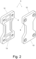
- Fig. 2 shows in detail and in a three-dimensional manner the front face or rear face of a web element 5.
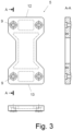
- Fig. 3 shows the previously described web element 5 in a front view, in a plan view and as a cross-sectional view in plane A-A.
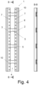
- Fig. 4 shows a side view and a cross-sectional view in plane B-B of the profile 1 according to fig. 1 .
- Fig. 5 shows an alternative embodiment of a profile 1 as a cross-sectional view and in a three-dimensional view.
- the profile 1 according to Fig. 5 likewise comprises a first limb 2 and a second limb 3. Both limbs 2, 3 consist of metallic material.
- the first limb 2 and the second limb 3 are connected to one another via a web 4.
- the web 4 is formed from a plurality of web elements 5, wherein the web elements 5 are connected in a form-fitting manner to the first limb 2 and the second limb 3.
- the web elements 5 consist of a synthetic material which can be injection moulded.
- the web elements 5 are formed as plates and are substantially flat.
- the profile 1 is formed as a C-shaped profile and comprises fastening flanges 14 to receive dry elements.
- the two fastening flanges 14 are disposed parallel to one another.
- the first limb 2 and the second limb 3 each comprise a fastening portion 6.
- the fastening portion 6 is formed as a strip and both fastening portions 6 are disposed in the same horizontal plane.
- the two fastening portions 6 are formed from the first limb 2 and the second limb 3 and point towards each other. Openings 7 in the form of circular holes are introduced into the fastening portions 6.
- the web elements 5 are fastened in the openings 7.
- the web elements 5 are fastened to the fastening portions 6 in that in each case, two web elements 5 are disposed back-to-back with respect to each other and thus receive the fastening portions 6 of the first limb 2 and second limb 3 between them.
- Each web element 5 comprises form-fitting elements 8 in the form of bores 9 and protrusions 11.
- the bores 9 and protrusions 11 of the form-fitting elements 8 of the web elements 5 are congruent to one another.
- the protrusions 11 can be inserted into the bores 9 in a form-fitting manner and latch in the bores 9.
- the web elements 5 each comprise a bore 9 and a protrusion 11 on the first edge 12 and on the second edge 13.
- the arrangement of bore 9 and protrusion 11 on the first edge 12 has point symmetry with the arrangement of bore 9 and protrusion 11 on the second edge 13.
- merely a single type of web elements 5 is sufficient to form the profile 1.
- a first web element 5 is fixed in the fastening portions 6 by the openings 7, and a second web element 5 is fastened, having been tilted by 180°, on the other web element 5.
- the two web elements 5 receive the fastening portions 6 between them.
- the two rear sides of the two web elements 5 face each other.
- the first edge 12 of one web element 5 is allocated to the second edge 13 of the other web element 5.
- Fig. 6 shows in detail and in a three-dimensional manner the front face or rear face of a web element 5 according to Fig. 5 .
- Fig. 7 shows the previously described web element 5 in a front view as well as two cross-sectional views: one in plane C-C and one in plane E-E.
- Fig. 8 shows a side view and a cross-sectional view in plane D-D of the profile 1 according to Fig. 5 .
- Fig. 9 shows a wall 15 comprising a plurality of profiles 1 according to Fig. 1 and a plurality of flat construction panels 16, which are fixed on the fastening flanges 14 of the profiles 1.
- the construction panels 16 are formed e.g. as gypsum plaster boards and are fixed in the fastening flanges 14 of the profile 1 with fastening means 17, e.g. in the form of screws.
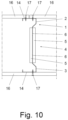
- Fig. 10 shows a wall 15 comprising a plurality of profiles 1 according to Fig. 5 and a plurality of flat construction panels 16 which are fixed on the fastening flanges 14 of the profiles 1.
- the construction panels 16 are formed e.g. as gypsum plaster boards and are fixed in the fastening flanges 14 of the profile 1 with fastening means 17, e.g. in the form of screws.
Landscapes
- Physics & Mathematics (AREA)
- Engineering & Computer Science (AREA)
- Architecture (AREA)
- Thermal Sciences (AREA)
- Electromagnetism (AREA)
- Civil Engineering (AREA)
- Structural Engineering (AREA)
- Connection Of Plates (AREA)
- Orthopedics, Nursing, And Contraception (AREA)
- Joining Of Building Structures In Genera (AREA)
- Finishing Walls (AREA)
Abstract
Description
- The invention relates to a profile for dry construction, comprising a first limb and a second limb which are connected to one another via a web.
- Such profiles are known e.g. from
DE 102 16 675 B4 . The profile forms a support structure and serves to receive flat construction panels e.g. gypsum plaster boards. The flat construction panels are fixedly fastened to the limbs of the profile. - The profiles are thus usually formed from metallic material. In this case, it is problematic that metallic materials frequently have good heat-conducting properties. If thermal separation is to be carried out by means of the wall erected using the profiles, the problem is that the metallic profiles, which extend from one side of the wall to the other side of the wall form a heat bridge via which a considerable heat transfer is possible.
- In the case of the previously known profile, a separation of the two limbs is effected by a separation gap, into which an elastic material is introduced and is connected to the limbs by an adhesive connection.
- A further problem is that sound is transmitted through the profile, wherein the propagation of sound within the profile is not disrupted.
- The object of the invention is to provide a profile for dry construction, which makes thermal decoupling of the two limbs possible and can be produced easily and inexpensively.
- This object is achieved by the features of
claim 1. The dependent claims refer to advantageous embodiments. - In order to achieve this object, the web is formed of web elements and the web elements are connected in a form-fitting manner to the first limb and the second limb. Owing to the fact that the web is formed from a plurality of web elements, thermal decoupling of the two limbs is already achieved independently of the selection of the material of the web elements. Due to the fact that the web elements are connected in a form-fitting manner to the first limb and the second limb, the profile is particularly easy and inexpensive to produce. It is merely necessary to fasten the web elements to both limbs. In particular, it is not necessary to provide additional connection means or to produce an adhesive connection between the elements.
- Furthermore, it is advantageous that sound propagation within the profile is reduced because the profile comprises multiple parts, and so improved sound decoupling is achieved.
- The first limb and the second limb can each comprise a fastening portion, wherein openings are introduced into the fastening portions, wherein the web elements are fastened in the openings. Thus the fastening portions are preferably formed as strips and disposed with respect to each other in a plane. Thus a plurality of openings are introduced into each fastening portion. This can be effected preferably in the form of a pattern of holes with circular openings at regular intervals. This makes possible a flexible arrangement of the web elements in the two limbs. For example, depending on the expected loading situation, the number of web elements can be increased or reduced in order to form the profile. The openings further improve the sound-decoupling properties of the profile.
- The web elements preferably have the form of plates. In the case of this design, the web elements are formed as flat elements and can thus be produced easily and inexpensively.
- The web elements are preferably provided with form-fitting elements, wherein the web elements are connected via the form-fitting elements to the fastening portions of the first limb and of the second limb. Thus, the form-fitting elements engage into the openings of the fastening portions so that the web elements are fixedly connected to the fastening portions of the first limb and of the second limb.
- The form-fitting elements can comprise bores or fastening elements, wherein the fastening elements are introduced into the bores. Thus, the web elements are disposed on one side of the fastening portions of the limbs and the fastening elements are disposed on the other side of the fastening portions and protrude through the openings of the limbs into the bores of the web elements.
- Thus, the fastening elements are fastened in the bores of the web elements, preferably by means of a snap-fit connection. For this purpose, the bores of the web elements on the side facing away from the fastening elements are provided with a cross-sectional extension. The fastening elements in turn comprise protrusions, on the free ends of which elastically tiltable conical cross-sectional extensions are disposed. These are deformed when being pressed into the bores and are fixedly braced in the cross-sectional extension. In this way, by means of the fastening element, the web element is fixedly fastened on the first limb or the second limb.
- According to an alternative embodiment, each web element can comprise form-fitting elements in the form of bores and protrusions, wherein in each case two web elements are allocated to one another. In this embodiment, the separate fastening elements are omitted. For fastening purposes, two web elements are preferably disposed back-to-back and receive the fastening portions of the first limb and second limb. This results in a mechanically particularly stable connection and a mechanically particularly stable profile.
- Thus the bores and protrusions of the form-fitting elements are designed in a preferably congruent manner. For joining purposes, the protrusion of a web element engages into the bore of the adjacent other web element. Thus the protrusions pass through the openings of the fastening portions of the limb.
- The web elements can comprise a first edge allocated to the first limb and a second edge allocated to the second limb, wherein a bore and a protrusion are disposed respectively on the first edge and on the second edge. Furthermore, the bore and protrusion are preferably arranged such that the bore and protrusion on the first edge have point symmetry with respect to the arrangement of the bore and protrusion on the second edge. In this embodiment, it is advantageous that a single embodiment of the web element will suffice to form the profile. For fastening purposes, a first web element is disposed in the openings of the two limbs and a second web element is fastened on the first web element in a mirror-symmetrical and back-to-back manner. Thus, the protrusions of the two web elements each pass through the openings of the two limbs. Furthermore, the protrusions of one web element engage into the bores of the other web element. Thus, the profile can be produced quickly and inexpensively. Furthermore, only one single forming tool is required in order to produce the web elements.
- The web elements preferably consist of a non-metallic material, in particular synthetic material. Thus a synthetic material which can be injection moulded is preferably used. In this case, it is advantageous that synthetic materials are inexpensive. Furthermore, synthetic materials have advantageous thermal properties. Synthetic materials have a relatively low level of heat conductivity, which effects thermal decoupling of the two limbs. Synthetic materials also have sound-decoupling properties, especially compared to metallic materials.
- In addition to the use of synthetic materials, composite materials are also particularly considered, e.g. in the form of fibre-reinforced synthetic material.
- The first limb and the second limb are preferably formed from metallic material. This permits in particular the processing of the profiles, or the mounting of wall elements on the profiles, using conventional means known from dry construction technology.
- Fastening flanges for receiving dry construction panels are formed from the first limb and from the second limb. Thus the limbs are preferably formed in such a way that flat elements are placed on the limbs, wherein two adjacent wall elements can also be disposed edge-to-edge on the limbs. The wall elements are preferably fastened by means of a screw connection. Drywall screws can be used for this purpose.
- The profile is preferably formed as a C-shaped profile. Such profiles are commonly used in dry construction.
- A wall in accordance with the invention comprises a plurality of profiles in accordance with the invention and at least one flat construction panel which is fixed on the fastening flanges of the profiles. Flat construction panels are preferably fixed on both sides of the profiles. Owing to both limbs of the profile being thermally decoupled by the separately formed web elements, a wall with good thermal insulation is produced.
- In the following, some embodiments of the profile in accordance with the invention will be explained in more detail with the help of the figures. The figures illustrate, in each case schematically:
- Fig. 1
- a cross-sectional view and a three-dimensional view of a first embodiment of the profile;
- Fig. 2
- a three-dimensional view of a web element according to the first embodiment;
- Fig. 3
- a front view and a cross-sectional view in plane A-A of a web element according to the first embodiment;
- Fig. 4
- a side view and a cross-sectional view in plane B-B of a profile according to the first embodiment;
- Fig. 5
- a cross-sectional view and a three-dimensional view of a second embodiment of the profile;
- Fig. 6
- a three-dimensional view of a web element according to the second embodiment;
- Fig. 7
- a front view and two cross-sectional views, one in plane C-C and one in plane E-E, of a web element according to the second embodiment;
- Fig. 8
- a side view and a cross-sectional view in plane D-D of a profile according to the second embodiment;
- Fig. 9
- a wall with a profile according to
figure 1 ; - Fig. 10
- a wall with a profile according to
figure 5 . -
Fig. 1 shows a cross-sectional view and a three-dimensional view of aprofile 1 for dry construction. Theprofile 1 comprises afirst limb 2 and asecond limb 3. Bothlimbs first limb 2 and thesecond limb 3 are connected to one another via aweb 4. Theweb 4 is formed from a plurality ofweb elements 5, wherein theweb elements 5 are connected in a form-fitting manner to thefirst limb 2 and thesecond limb 3. Theweb elements 5 consist of a synthetic material which can be injection moulded. - The
profile 1 is formed as a C-shaped profile and comprisesfastening flanges 14 to receive dry elements. The twofastening flanges 14 are disposed parallel to one another. Thefirst limb 2 and thesecond limb 3 each comprise afastening portion 6. Thefastening portion 6 is formed as a strip and bothfastening portions 6 are disposed in the same horizontal plane. The twofastening portions 6 are formed from thefirst limb 2 and thesecond limb 3 and point towards each other.Openings 7 in the form of circular holes are introduced into thefastening portions 6. Theweb elements 5 are fastened in theopenings 7. - The
web elements 5 are formed as plates and are substantially flat. - The
web elements 5 comprise afirst edge 12 allocated to thefirst limb 2 and asecond edge 13 allocated to thesecond limb 3. Form-fitting elements 8 are disposed in the region of bothedges web elements 5 are connected to thefastening portions 6 of thefirst limb 2 and of thesecond limb 3 via the form-fitting elements 8. - In the present embodiment, the form-
fitting elements 8 comprise bores 9 andfastening elements 10. In order to form theprofile 1,web elements 5 are disposed on one side of thefastening portions 6 andfastening elements 10 are disposed on the other side of thefastening portions 6 and protrude through theopening 7 into thebore 9 of theweb elements 5. - The
fastening elements 10 are formed as a latching element and preferably have a button-like shape. Thefastening elements 10 comprisepins 17 centrally provided with undercuts. Thebores 9 of theweb elements 5 have a cross-sectional extension on the side facing away from thefastening portion 6. Thepin 17, which is formed conically at the free end, is deformed when being pressed into thebore 9, in order to be finally braced in a form-fitting manner in the cross-sectional extension. In this way, by means of thefastening element 10, theweb element 5 is fixedly fastened on thefirst limb 2 or thesecond limb 3. -
Fig. 2 shows in detail and in a three-dimensional manner the front face or rear face of aweb element 5. -
Fig. 3 shows the previously describedweb element 5 in a front view, in a plan view and as a cross-sectional view in plane A-A. -
Fig. 4 shows a side view and a cross-sectional view in plane B-B of theprofile 1 according tofig. 1 . -
Fig. 5 shows an alternative embodiment of aprofile 1 as a cross-sectional view and in a three-dimensional view. Theprofile 1 according toFig. 5 likewise comprises afirst limb 2 and asecond limb 3. Bothlimbs first limb 2 and thesecond limb 3 are connected to one another via aweb 4. Thus theweb 4 is formed from a plurality ofweb elements 5, wherein theweb elements 5 are connected in a form-fitting manner to thefirst limb 2 and thesecond limb 3. Theweb elements 5 consist of a synthetic material which can be injection moulded. Theweb elements 5 are formed as plates and are substantially flat. - The
profile 1 is formed as a C-shaped profile and comprisesfastening flanges 14 to receive dry elements. The twofastening flanges 14 are disposed parallel to one another. Thefirst limb 2 and thesecond limb 3 each comprise afastening portion 6. Thefastening portion 6 is formed as a strip and bothfastening portions 6 are disposed in the same horizontal plane. The twofastening portions 6 are formed from thefirst limb 2 and thesecond limb 3 and point towards each other.Openings 7 in the form of circular holes are introduced into thefastening portions 6. Theweb elements 5 are fastened in theopenings 7. - In the case of the present embodiment, the
web elements 5 are fastened to thefastening portions 6 in that in each case, twoweb elements 5 are disposed back-to-back with respect to each other and thus receive thefastening portions 6 of thefirst limb 2 andsecond limb 3 between them. - Each
web element 5 comprises form-fitting elements 8 in the form ofbores 9 andprotrusions 11. Thus thebores 9 andprotrusions 11 of the form-fitting elements 8 of theweb elements 5 are congruent to one another. Theprotrusions 11 can be inserted into thebores 9 in a form-fitting manner and latch in thebores 9. Theweb elements 5 each comprise abore 9 and aprotrusion 11 on thefirst edge 12 and on thesecond edge 13. Thus, the arrangement ofbore 9 andprotrusion 11 on thefirst edge 12 has point symmetry with the arrangement ofbore 9 andprotrusion 11 on thesecond edge 13. In this respect, merely a single type ofweb elements 5 is sufficient to form theprofile 1. Afirst web element 5 is fixed in thefastening portions 6 by theopenings 7, and asecond web element 5 is fastened, having been tilted by 180°, on theother web element 5. Thus the twoweb elements 5 receive thefastening portions 6 between them. In this embodiment, the two rear sides of the twoweb elements 5 face each other. Furthermore, thefirst edge 12 of oneweb element 5 is allocated to thesecond edge 13 of theother web element 5. -
Fig. 6 shows in detail and in a three-dimensional manner the front face or rear face of aweb element 5 according toFig. 5 . -
Fig. 7 shows the previously describedweb element 5 in a front view as well as two cross-sectional views: one in plane C-C and one in plane E-E. -
Fig. 8 shows a side view and a cross-sectional view in plane D-D of theprofile 1 according toFig. 5 . -
Fig. 9 shows a wall 15 comprising a plurality ofprofiles 1 according toFig. 1 and a plurality offlat construction panels 16, which are fixed on thefastening flanges 14 of theprofiles 1. Theconstruction panels 16 are formed e.g. as gypsum plaster boards and are fixed in thefastening flanges 14 of theprofile 1 with fastening means 17, e.g. in the form of screws. -
Fig. 10 shows a wall 15 comprising a plurality ofprofiles 1 according toFig. 5 and a plurality offlat construction panels 16 which are fixed on thefastening flanges 14 of theprofiles 1. Theconstruction panels 16 are formed e.g. as gypsum plaster boards and are fixed in thefastening flanges 14 of theprofile 1 with fastening means 17, e.g. in the form of screws.
Claims (14)
- Profile (1) for dry construction, comprising a first limb (2) and a second limb (3), which are connected to each other via a web (4), characterised in that the web (4) is formed of web elements (5) and that the web elements (5) are connected in a form-fitting manner to the first limb (2) and the second limb (3).
- Profile according to claim 1, characterised in that the first limb (2) and the second limb (3) each comprise a fastening portion (6), wherein openings (7) are introduced into the fastening portions (6), wherein the web elements (5) are fastened in the openings (7).
- Profile according to claim 1 or 2, characterised in that the web elements (5) are formed as plates.
- Profile according to any one of claims 1 to 3, characterised in that the web elements (5) are provided with form-fitting elements (8), wherein the web elements (5) are connected to the fastening portions (6) of the first limb (2) and of the second limb (3) by the form-fitting elements (8).
- Profile according to claim 4, characterised in that the form-fitting elements (8) comprise bores (9), wherein the web elements (5) are disposed on one side of the fastening portions (6) and fastening elements (10) are disposed on the other side of the fastening portions (6) and protrude through the openings (7) into the bore (9).
- Profile according to claim 4, characterised in that each web element (5) comprises form-fitting elements (8) in the form of bores (9) and protrusions (11), wherein in each case two web elements (5) are allocated to one another.
- Profile according to claim 6, characterised in that the bores (9) and protrusions (11) of the form-fitting elements (8) of the web elements (5) are congruent to one another.
- Profile according to claim 6 or 7, characterised in that the web elements (5) comprise a first edge (12) allocated to the first limb (2) and a second edge (13) allocated to the second limb (3), wherein a bore (9) and a protrusion (11) are disposed respectively on the first edge (12) and on the second edge (13).
- Profile according to claim 8, characterised in that the arrangement of bore (9) and protrusion (11) on the first edge (12) has point symmetry with the arrangement of bore (9) and protrusion (11) on the second edge (13).
- Profile according to any one of claims 1 to 9, characterised in that the web elements (5) are formed from synthetic material.
- Profile according to any one of claims 1 to 10, characterised in that at least one limb (2, 3) is formed from metallic material.
- Profile according to any one of claims 1 to 11, characterised in that fastening flanges (14) for receiving dry construction elements are formed from the first limb (2) and the second limb (3).
- Profile according to any one of claims 1 to 12, characterised in that the profile (1) is formed as a C-shaped profile.
- Wall (15), comprising a plurality of profiles (1) according to any one of the preceding claims and at least one flat construction panel (16) which is fixed on the fastening flanges (14) of the profiles (1).
Priority Applications (2)
| Application Number | Priority Date | Filing Date | Title |
|---|---|---|---|
| ES23201898T ES3065868T3 (en) | 2018-12-19 | 2018-12-19 | Profile |
| EP23201898.6A EP4279678B1 (en) | 2018-12-19 | 2018-12-19 | Profile |
Applications Claiming Priority (3)
| Application Number | Priority Date | Filing Date | Title |
|---|---|---|---|
| EP18833389.2A EP3899160B1 (en) | 2018-12-19 | 2018-12-19 | Profile |
| EP23201898.6A EP4279678B1 (en) | 2018-12-19 | 2018-12-19 | Profile |
| PCT/EP2018/000569 WO2020125916A1 (en) | 2018-12-19 | 2018-12-19 | Profile |
Related Parent Applications (2)
| Application Number | Title | Priority Date | Filing Date |
|---|---|---|---|
| EP18833389.2A Division EP3899160B1 (en) | 2018-12-19 | 2018-12-19 | Profile |
| EP18833389.2A Division-Into EP3899160B1 (en) | 2018-12-19 | 2018-12-19 | Profile |
Publications (4)
| Publication Number | Publication Date |
|---|---|
| EP4279678A2 true EP4279678A2 (en) | 2023-11-22 |
| EP4279678A3 EP4279678A3 (en) | 2023-12-13 |
| EP4279678B1 EP4279678B1 (en) | 2026-02-25 |
| EP4279678C0 EP4279678C0 (en) | 2026-02-25 |
Family
ID=65013636
Family Applications (2)
| Application Number | Title | Priority Date | Filing Date |
|---|---|---|---|
| EP18833389.2A Active EP3899160B1 (en) | 2018-12-19 | 2018-12-19 | Profile |
| EP23201898.6A Active EP4279678B1 (en) | 2018-12-19 | 2018-12-19 | Profile |
Family Applications Before (1)
| Application Number | Title | Priority Date | Filing Date |
|---|---|---|---|
| EP18833389.2A Active EP3899160B1 (en) | 2018-12-19 | 2018-12-19 | Profile |
Country Status (6)
| Country | Link |
|---|---|
| EP (2) | EP3899160B1 (en) |
| JP (2) | JP7375015B2 (en) |
| ES (2) | ES3065868T3 (en) |
| PL (1) | PL3899160T3 (en) |
| UA (1) | UA126952C2 (en) |
| WO (1) | WO2020125916A1 (en) |
Families Citing this family (3)
| Publication number | Priority date | Publication date | Assignee | Title |
|---|---|---|---|---|
| LU500643B1 (en) * | 2021-09-09 | 2023-03-09 | Cistron Innovations Sarl | Modular structural components |
| US20250223797A1 (en) * | 2021-10-21 | 2025-07-10 | Lynx Systems Pty Ltd | Building frame system |
| WO2025031555A1 (en) | 2023-08-04 | 2025-02-13 | Knauf Gips Kg | Wall stud for a dry construction structure, dry construction system and dry construction wall with such a wall stud, and method for erecting a dry construction wall |
Citations (1)
| Publication number | Priority date | Publication date | Assignee | Title |
|---|---|---|---|---|
| DE10216675B4 (en) | 2001-05-07 | 2013-04-18 | Richter-System Gmbh & Co Kg | Sound insulating profile |
Family Cites Families (11)
| Publication number | Priority date | Publication date | Assignee | Title |
|---|---|---|---|---|
| JPS51140322A (en) * | 1975-05-28 | 1976-12-03 | Takao Izuhara | Wall body for construction |
| JPS5884411U (en) * | 1981-12-03 | 1983-06-08 | パイオニア株式会社 | Bush rivet structure |
| JPH0242892Y2 (en) * | 1985-06-21 | 1990-11-15 | ||
| US5720144A (en) * | 1996-03-07 | 1998-02-24 | Knudson; Gary A. | Metal beams with thermal break and methods |
| US6250042B1 (en) * | 1996-06-17 | 2001-06-26 | University Of Central Florida | Additional metal and wood composite framing members for residential and light commercial construction |
| US20050183382A1 (en) * | 2002-06-06 | 2005-08-25 | Jensen Gary L. | Method of making members with a thermal break |
| NZ545161A (en) * | 2003-08-25 | 2008-03-28 | Building Solutions Pty Ltd | Building panels to provide panel formwork for concrete walls. |
| US7587877B2 (en) * | 2003-10-28 | 2009-09-15 | Best Joist Inc | Cold-formed steel joists |
| DE10352247A1 (en) * | 2003-11-08 | 2005-06-09 | König GmbH & Co. KG | Metal profile e.g. CW profile, for column e.g. pillar, has connecting web plate with connecting unit that is connected between flange sections at regular intervals by welding, where connecting unit is made of sound proof material |
| WO2018147743A1 (en) * | 2017-02-07 | 2018-08-16 | Hunton Fiber As | Sound insulating building construction element |
| ES2765820T3 (en) * | 2017-04-07 | 2020-06-11 | Knauf Aquapanel Gmbh & Co Kg | Profile for installing a non-bearing exterior wall for a building, non-bearing wall for a building comprising at least one profile of this type and a building comprising a non-bearing exterior wall of this type |
-
2018
- 2018-12-19 EP EP18833389.2A patent/EP3899160B1/en active Active
- 2018-12-19 PL PL18833389.2T patent/PL3899160T3/en unknown
- 2018-12-19 UA UAA202103445A patent/UA126952C2/en unknown
- 2018-12-19 JP JP2021532220A patent/JP7375015B2/en active Active
- 2018-12-19 WO PCT/EP2018/000569 patent/WO2020125916A1/en not_active Ceased
- 2018-12-19 ES ES23201898T patent/ES3065868T3/en active Active
- 2018-12-19 ES ES18833389T patent/ES2968277T3/en active Active
- 2018-12-19 EP EP23201898.6A patent/EP4279678B1/en active Active
-
2023
- 2023-10-25 JP JP2023183556A patent/JP7739379B2/en active Active
Patent Citations (1)
| Publication number | Priority date | Publication date | Assignee | Title |
|---|---|---|---|---|
| DE10216675B4 (en) | 2001-05-07 | 2013-04-18 | Richter-System Gmbh & Co Kg | Sound insulating profile |
Also Published As
| Publication number | Publication date |
|---|---|
| ES2968277T3 (en) | 2024-05-08 |
| JP7375015B2 (en) | 2023-11-07 |
| EP3899160A1 (en) | 2021-10-27 |
| WO2020125916A1 (en) | 2020-06-25 |
| ES3065868T3 (en) | 2026-05-08 |
| JP2022517507A (en) | 2022-03-09 |
| JP2023182842A (en) | 2023-12-26 |
| EP4279678B1 (en) | 2026-02-25 |
| EP3899160C0 (en) | 2023-11-22 |
| PL3899160T3 (en) | 2024-03-04 |
| JP7739379B2 (en) | 2025-09-16 |
| UA126952C2 (en) | 2023-02-22 |
| EP4279678C0 (en) | 2026-02-25 |
| EP3899160B1 (en) | 2023-11-22 |
| EP4279678A3 (en) | 2023-12-13 |
Similar Documents
| Publication | Publication Date | Title |
|---|---|---|
| JP7739379B2 (en) | Profile | |
| US9506252B2 (en) | Extruded profile for a fitted panel and fitted panel comprising said extruded profile | |
| US11187031B2 (en) | Fastening system and window shade including the same | |
| US6238028B1 (en) | Rack with several assembly levels | |
| US3251168A (en) | Exterior wall covering and support therefor | |
| CN108884848A (en) | mounting assembly | |
| CN104145123B (en) | Assembly device | |
| EP4095333A1 (en) | Carrier for a linear ceiling panel | |
| RU2317379C2 (en) | C-shaped profile | |
| US6155434A (en) | Assembly rail for a switching cabinet | |
| RU2776745C1 (en) | Profile | |
| CN1293474A (en) | Metallic frame in particular, vertical column of etectric cabinet | |
| KR20190001594U (en) | System wall partition | |
| RU186957U1 (en) | Structural profile for the assembly of furniture components | |
| CN215716330U (en) | Assembled curtain wall assembly structure | |
| PL169144B1 (en) | Connector for connecting construction elements PL | |
| DK200000016U3 (en) | Shelving system of plates and bolt assemblies | |
| JPH02240363A (en) | Executing method of tile and tile used for the same method | |
| CN221800280U (en) | Panel connecting piece, connection structure and bathroom cabinet | |
| CN222264794U (en) | Hanging cabinet installation fixing structure | |
| CN219219514U (en) | Suspended ceiling access window and integral bathroom suspended ceiling structure | |
| US10626904B2 (en) | Aluminum-extruded frame curve module structure | |
| CN112128183A (en) | Connection structure, connection structure and bathroom cabinet of board | |
| KR200378475Y1 (en) | Apparatus for fixing prefabricated wall panel to a wall | |
| JP2002004541A (en) | Execution structure for plate-shaped building material |
Legal Events
| Date | Code | Title | Description |
|---|---|---|---|
| PUAI | Public reference made under article 153(3) epc to a published international application that has entered the european phase |
Free format text: ORIGINAL CODE: 0009012 |
|
| STAA | Information on the status of an ep patent application or granted ep patent |
Free format text: STATUS: THE APPLICATION HAS BEEN PUBLISHED |
|
| REG | Reference to a national code |
Ref legal event code: R079 Free format text: PREVIOUS MAIN CLASS: E04C0003290000 Ref country code: DE Ref document number: 602018089511 Country of ref document: DE Ipc: E04B0002740000 |
|
| PUAL | Search report despatched |
Free format text: ORIGINAL CODE: 0009013 |
|
| AC | Divisional application: reference to earlier application |
Ref document number: 3899160 Country of ref document: EP Kind code of ref document: P |
|
| AK | Designated contracting states |
Kind code of ref document: A2 Designated state(s): AL AT BE BG CH CY CZ DE DK EE ES FI FR GB GR HR HU IE IS IT LI LT LU LV MC MK MT NL NO PL PT RO RS SE SI SK SM TR |
|
| AK | Designated contracting states |
Kind code of ref document: A3 Designated state(s): AL AT BE BG CH CY CZ DE DK EE ES FI FR GB GR HR HU IE IS IT LI LT LU LV MC MK MT NL NO PL PT RO RS SE SI SK SM TR |
|
| RIC1 | Information provided on ipc code assigned before grant |
Ipc: E04C 3/29 20060101ALN20231108BHEP Ipc: E04C 3/07 20060101ALN20231108BHEP Ipc: E04B 2/74 20060101AFI20231108BHEP |
|
| RIN1 | Information on inventor provided before grant (corrected) |
Inventor name: MAHLHOFF, ALFRED Inventor name: MYRONOV, ALEXANDER Inventor name: RACHWITZ, SYLVIA |
|
| STAA | Information on the status of an ep patent application or granted ep patent |
Free format text: STATUS: REQUEST FOR EXAMINATION WAS MADE |
|
| 17P | Request for examination filed |
Effective date: 20240607 |
|
| RBV | Designated contracting states (corrected) |
Designated state(s): AL AT BE BG CH CY CZ DE DK EE ES FI FR GB GR HR HU IE IS IT LI LT LU LV MC MK MT NL NO PL PT RO RS SE SI SK SM TR |
|
| STAA | Information on the status of an ep patent application or granted ep patent |
Free format text: STATUS: EXAMINATION IS IN PROGRESS |
|
| 17Q | First examination report despatched |
Effective date: 20240821 |
|
| GRAP | Despatch of communication of intention to grant a patent |
Free format text: ORIGINAL CODE: EPIDOSNIGR1 |
|
| STAA | Information on the status of an ep patent application or granted ep patent |
Free format text: STATUS: GRANT OF PATENT IS INTENDED |
|
| RIC1 | Information provided on ipc code assigned before grant |
Ipc: E04B 2/74 20060101AFI20250626BHEP Ipc: E04C 3/07 20060101ALN20250626BHEP Ipc: E04C 3/29 20060101ALN20250626BHEP |
|
| INTG | Intention to grant announced |
Effective date: 20250709 |
|
| GRAJ | Information related to disapproval of communication of intention to grant by the applicant or resumption of examination proceedings by the epo deleted |
Free format text: ORIGINAL CODE: EPIDOSDIGR1 |
|
| STAA | Information on the status of an ep patent application or granted ep patent |
Free format text: STATUS: EXAMINATION IS IN PROGRESS |
|
| GRAP | Despatch of communication of intention to grant a patent |
Free format text: ORIGINAL CODE: EPIDOSNIGR1 |
|
| STAA | Information on the status of an ep patent application or granted ep patent |
Free format text: STATUS: GRANT OF PATENT IS INTENDED |
|
| INTG | Intention to grant announced |
Effective date: 20250924 |
|
| RIC1 | Information provided on ipc code assigned before grant |
Ipc: E04B 2/74 20060101AFI20250912BHEP Ipc: E04C 3/07 20060101ALN20250912BHEP Ipc: E04C 3/29 20060101ALN20250912BHEP |
|
| INTG | Intention to grant announced |
Effective date: 20250924 |
|
| GRAS | Grant fee paid |
Free format text: ORIGINAL CODE: EPIDOSNIGR3 |
|
| GRAA | (expected) grant |
Free format text: ORIGINAL CODE: 0009210 |
|
| STAA | Information on the status of an ep patent application or granted ep patent |
Free format text: STATUS: THE PATENT HAS BEEN GRANTED |
|
| AC | Divisional application: reference to earlier application |
Ref document number: 3899160 Country of ref document: EP Kind code of ref document: P |
|
| AK | Designated contracting states |
Kind code of ref document: B1 Designated state(s): AL AT BE BG CH CY CZ DE DK EE ES FI FR GB GR HR HU IE IS IT LI LT LU LV MC MK MT NL NO PL PT RO RS SE SI SK SM TR |
|
| REG | Reference to a national code |
Ref country code: CH Ref legal event code: F10 Free format text: ST27 STATUS EVENT CODE: U-0-0-F10-F00 (AS PROVIDED BY THE NATIONAL OFFICE) Effective date: 20260225 Ref country code: GB Ref legal event code: FG4D |
|
| REG | Reference to a national code |
Ref country code: DE Ref legal event code: R096 Ref document number: 602018089511 Country of ref document: DE |
|
| REG | Reference to a national code |
Ref country code: IE Ref legal event code: FG4D |
|
| U01 | Request for unitary effect filed |
Effective date: 20260317 |
|
| U07 | Unitary effect registered |
Designated state(s): AT BE BG DE DK EE FI FR IT LT LU LV MT NL PT RO SE SI Effective date: 20260323 |
|
| REG | Reference to a national code |
Ref country code: ES Ref legal event code: FG2A Ref document number: 3065868 Country of ref document: ES Kind code of ref document: T3 Effective date: 20260508 |