EP4279433A1 - Elevator car assembly - Google Patents
Elevator car assembly Download PDFInfo
- Publication number
- EP4279433A1 EP4279433A1 EP22305738.1A EP22305738A EP4279433A1 EP 4279433 A1 EP4279433 A1 EP 4279433A1 EP 22305738 A EP22305738 A EP 22305738A EP 4279433 A1 EP4279433 A1 EP 4279433A1
- Authority
- EP
- European Patent Office
- Prior art keywords
- connector portion
- elevator car
- elevator
- operating panel
- car operating
- Prior art date
- Legal status (The legal status is an assumption and is not a legal conclusion. Google has not performed a legal analysis and makes no representation as to the accuracy of the status listed.)
- Pending
Links
Images



Classifications
-
- B—PERFORMING OPERATIONS; TRANSPORTING
- B66—HOISTING; LIFTING; HAULING
- B66B—ELEVATORS; ESCALATORS OR MOVING WALKWAYS
- B66B1/00—Control systems of elevators in general
- B66B1/34—Details, e.g. call counting devices, data transmission from car to control system, devices giving information to the control system
- B66B1/46—Adaptations of switches or switchgear
- B66B1/50—Adaptations of switches or switchgear with operating or control mechanisms mounted in the car or cage or in the lift well or hoistway
-
- B—PERFORMING OPERATIONS; TRANSPORTING
- B66—HOISTING; LIFTING; HAULING
- B66B—ELEVATORS; ESCALATORS OR MOVING WALKWAYS
- B66B1/00—Control systems of elevators in general
- B66B1/34—Details, e.g. call counting devices, data transmission from car to control system, devices giving information to the control system
- B66B1/46—Adaptations of switches or switchgear
- B66B1/461—Adaptations of switches or switchgear characterised by their shape or profile
- B66B1/466—Adaptations of switches or switchgear characterised by their shape or profile facilitating maintenance, installation, removal, replacement or repair
-
- B—PERFORMING OPERATIONS; TRANSPORTING
- B66—HOISTING; LIFTING; HAULING
- B66B—ELEVATORS; ESCALATORS OR MOVING WALKWAYS
- B66B1/00—Control systems of elevators in general
- B66B1/34—Details, e.g. call counting devices, data transmission from car to control system, devices giving information to the control system
- B66B1/46—Adaptations of switches or switchgear
- B66B1/467—Adaptations of switches or switchgear characterised by their mounting position
-
- B—PERFORMING OPERATIONS; TRANSPORTING
- B66—HOISTING; LIFTING; HAULING
- B66B—ELEVATORS; ESCALATORS OR MOVING WALKWAYS
- B66B11/00—Main component parts of lifts in, or associated with, buildings or other structures
- B66B11/001—Arrangement of controller, e.g. location
- B66B11/002—Arrangement of controller, e.g. location in the hoistway
- B66B11/0025—Arrangement of controller, e.g. location in the hoistway on the car
-
- B—PERFORMING OPERATIONS; TRANSPORTING
- B66—HOISTING; LIFTING; HAULING
- B66B—ELEVATORS; ESCALATORS OR MOVING WALKWAYS
- B66B11/00—Main component parts of lifts in, or associated with, buildings or other structures
- B66B11/0065—Roping
- B66B11/008—Roping with hoisting rope or cable operated by frictional engagement with a winding drum or sheave
-
- B—PERFORMING OPERATIONS; TRANSPORTING
- B66—HOISTING; LIFTING; HAULING
- B66B—ELEVATORS; ESCALATORS OR MOVING WALKWAYS
- B66B11/00—Main component parts of lifts in, or associated with, buildings or other structures
- B66B11/02—Cages, i.e. cars
- B66B11/0206—Car frames
-
- B—PERFORMING OPERATIONS; TRANSPORTING
- B66—HOISTING; LIFTING; HAULING
- B66B—ELEVATORS; ESCALATORS OR MOVING WALKWAYS
- B66B11/00—Main component parts of lifts in, or associated with, buildings or other structures
- B66B11/02—Cages, i.e. cars
- B66B11/0226—Constructional features, e.g. walls assembly, decorative panels, comfort equipment, thermal or sound insulation
-
- B—PERFORMING OPERATIONS; TRANSPORTING
- B66—HOISTING; LIFTING; HAULING
- B66B—ELEVATORS; ESCALATORS OR MOVING WALKWAYS
- B66B11/00—Main component parts of lifts in, or associated with, buildings or other structures
- B66B11/02—Cages, i.e. cars
- B66B11/0226—Constructional features, e.g. walls assembly, decorative panels, comfort equipment, thermal or sound insulation
- B66B11/0246—Maintenance features
-
- B—PERFORMING OPERATIONS; TRANSPORTING
- B66—HOISTING; LIFTING; HAULING
- B66B—ELEVATORS; ESCALATORS OR MOVING WALKWAYS
- B66B11/00—Main component parts of lifts in, or associated with, buildings or other structures
- B66B11/02—Cages, i.e. cars
- B66B11/0226—Constructional features, e.g. walls assembly, decorative panels, comfort equipment, thermal or sound insulation
- B66B11/0253—Fixation of wall panels
-
- H—ELECTRICITY
- H01—ELECTRIC ELEMENTS
- H01R—ELECTRICALLY-CONDUCTIVE CONNECTIONS; STRUCTURAL ASSOCIATIONS OF A PLURALITY OF MUTUALLY-INSULATED ELECTRICAL CONNECTING ELEMENTS; COUPLING DEVICES; CURRENT COLLECTORS
- H01R13/00—Details of coupling devices of the kinds covered by groups H01R12/70 or H01R24/00 - H01R33/00
- H01R13/73—Means for mounting coupling parts to apparatus or structures, e.g. to a wall
- H01R13/74—Means for mounting coupling parts in openings of a panel
-
- B—PERFORMING OPERATIONS; TRANSPORTING
- B66—HOISTING; LIFTING; HAULING
- B66B—ELEVATORS; ESCALATORS OR MOVING WALKWAYS
- B66B2201/00—Aspects of control systems of elevators
- B66B2201/40—Details of the change of control mode
- B66B2201/46—Switches or switchgear
- B66B2201/4607—Call registering systems
- B66B2201/4623—Wherein the destination is registered after boarding
Definitions
- This disclosure relates to an elevator car operating panel, an elevator cab and an elevator car assembly including an elevator cab and an elevator car operating panel.
- Elevator cars generally include an elevator car operating panel (“COP"), which is provided inside the elevator car.
- the COP may include various electronic components, for example buttons for selecting a desired landing floor, a display screen, an emergency stop switch, an alarm button, door open and close buttons and maintenance switches.
- Each of the electronic components generally require manual wiring between the COP and a junction box, which is typically situated on top of the elevator car.
- This manual wiring leads to complex maintenance procedures that are difficult to carry out in situ.
- it is difficult and time consuming to update the COP for example to add additional features, replace existing components, or provide an aesthetic update, and such updates often require a complete replacement of the elevator car enclosure, which can be costly.
- the elevator car operating panel and elevator car assembly according to the present disclosure seeks to address one or more of these shortcomings.
- an elevator car assembly comprising:
- one of the first and second connector portion is a male connector portion and the other of the first and second connector portion is a female connector portion.
- the first connector portion is configured for insertion into the second connector portion.
- the first connector portion comprises at least one pin contact and the second connector portion comprises at least one receptacle contact configured to cooperate with the at least one pin contact.
- the first connector portion comprises at least one receptacle contact and the second connector portion comprises at least one pin contact configured to cooperate with the at least one receptacle contact.
- first connector portion and the second connector portion are configured to push fit together.
- the first connector portion is further configured to form a releasable data connection with the second connector portion.
- the elevator car operating panel comprises a printed circuit board between the front surface and the rear surface, and the first connector portion is electrically coupled to the printed circuit board.
- the second connector portion is electrically coupled to circuitry on the elevator cab.
- the elevator car operating panel is configured for releasably mounting onto the at least one elevator cab wall.
- the elevator car operating panel comprises a mechanical coupling configured to releasably couple with a corresponding coupling on the at least one elevator cab wall.
- the mechanical coupling comprises a first part of a hinge mechanism
- the corresponding coupling comprises a second part of a hinge mechanism
- the first part of the hinge mechanism is configured to cooperate with the second part of the hinge mechanism such that the elevator car operating panel hinges with respect to the at least one elevator cab wall.
- the elevator car assembly further comprises at least one securing element configured to secure the elevator car operating panel in a mounted position with respect to the at least one elevator cab wall.
- the user interface comprises at least one elevator control comprising at least one of a switch, a button, and a display, each accessible through or disposed upon the front surface of the elevator car operating panel.
- an elevator cab comprising:
- an elevator car operating panel comprising: a user interface on a front surface of the elevator car operating panel and a first connector portion on a rear surface of the elevator car operating panel; wherein the first connector portion is configured to form a releasable electrical connection with a second connector portion provided on at least one wall of an elevator cab.
- Various examples described herein advantageously provide an elevator car operating panel that is simple to install and easy to replace compared to existing elevator car operating panels.
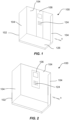
- FIG 1 illustrates an elevator car assembly 100.
- the elevator car assembly 100 includes an elevator cab 102 including a plurality of walls 104.
- the elevator cab 102 of Figure 1 is shown with an open side, though it will be appreciated that the elevator cab 102 will generally include a further wall and elevator doors for access into the elevator cab 102.
- access to the elevator cab 102 may be provided in the direction of the arrow A through sliding doors provided in place of at least part of the elevator cab wall 104.
- the elevator car assembly 100 further includes an elevator car operating panel 106, which is mounted onto one of the plurality of elevator cab walls 104.
- the elevator car operating panel 106 includes a user interface 124, which may include various elevator controls.
- the elevator controls may, for example, include buttons to select a destination floor, maintenance switches, and a display which may display information to the user such as a selected destination floor, a current position floor, and a direction of movement of the elevator car assembly 100.
- the elevator car operating panel 106 is sized to extend over a portion of one of the plurality of elevator cab walls 104, extending from a floor 126 of the elevator cab 102 to a ceiling of the elevator cab 102. In other examples, the elevator car operating panel 106 may be sized to extend over the entirety of the width of the elevator cab wall 104. In other examples, such as that shown in Figure 2 , the elevator car operating panel 106 may be configured to extend over a portion of the height and width of the elevator cab wall 104. It will be appreciated that the elevator car operating panel 106 may be configured with a different size and shape according to the number and type of elevator controls included on the elevator car operating panel 106 and the aesthetic requirements of the elevator cab 102.
- FIGS 3 and 4 respectively show schematic views of a sectional side view of an elevator car operating panel 106 and an elevator cab wall 104 to which it is mounted.
- the elevator car operating panel 106 includes a front surface 108 and a rear surface 110.
- the user interface 124 is provided on the front surface 108 such that each of the elevator controls may be accessible through or disposed upon the front surface 108 of the elevator car operating panel 106.
- the elevator car operating panel 106 further includes a first connector portion 112 provided on the rear surface 110.
- the elevator cab wall 104 onto which the elevator car operating panel 106 is mounted, includes a second connector portion 114.
- the first connector portion 112 is configured to form a releasable electrical connection with the second connector portion 114. That is, the first connector portion 112 is configured to cooperate with the second connector portion 114 to form the releasable electrical connection.
- the elevator control panel 106 may include a printed circuit board between the front surface 108 and the rear surface 110.
- the first connector portion 112 may be electrically coupled to the printed circuit board.
- the first connector portion 112 may be a male connector soldered onto the printed circuit board.
- the second connector portion 114 is electrically coupled to circuitry on or in the elevator cab 102.
- the second connector portion 114 may be a female wire connector configured to connect with wires on or in the elevator cab 102.
- first connector portion 112 and second connector portion 114 are further configured to form a data connection for transfer of data. This may be utilised for communication of the elevator car operating panel 106 with an elevator controller, for example.
- a third connector portion may be provided on the elevator car operating panel 106 and a fourth connector portion may be provided on the elevator cab wall 104.
- the third and fourth connector portions may be configured to cooperate to form a dedicated data connection that is independent of the electrical connection. This may be advantageous as a separate data connection may provide higher speed data transfer.
- the third and fourth connector portions may be configured similarly to the first and second connector portions 112, 114 as described in more detail below.
- One of the first and second connector portion 112, 114 may be a male connector portion and the other of the first and second connector portion 112, 114 may be a female connector portion.
- first connector portion 112 is a male connector portion and the second connector portion 114 is a female connector portion.
- first connector portion 112 may be a female connector portion and the second connector portion 114 may be a male connector portion.
- the first connector portion 112 is configured such that it can be inserted or plugged into the second connector portion 114 to form the electrical connection.
- the first connector portion 112 and the second connector portion 114 may be configured to form a push fit connection. In this way, during installation or maintenance it is possible to simply push together the first and second connector portions 112, 114 to form the electrical connection, and pull them apart to release the electrical connection. As such, this mitigates the need for any tooling to electrically connect or disconnect the elevator car operating panel 106 with the elevator cab wall 104.
- the first connector portion 112 may include a plurality of pin contacts and the second connector portion 114 may include a plurality of receptacle contacts configured to cooperate with the plurality of pin contacts.
- the pin contacts are configured to be slidably received in the receptacle contacts such that a releasable electrical connection may be formed.
- first and second connector portions 112, 114 may be suitable for use as the first and second connector portions 112, 114.
- standard connectors including HDMI, fibre, USB, or USB-C may be utilized.
- a custom connector designed specifically for the elevator car operating panel 106 may be utilised.
- a connector configured to provide both electrical connection and data connection may be used.
- the first connector portion may include both electrical contacts and data contacts configured to engage with corresponding contacts on the second connector portion.
- the elevator car operating panel 106 may further be configured for releasably mounting onto the elevator cab wall 104.
- the elevator car operating panel 106 may include a mechanical coupling 116 configured to releasably couple with a corresponding coupling 118 on the elevator cab wall 104. In this way, the elevator car operating panel 106 can be relatively easily installed, removed and replaced.
- the mechanical coupling 116 includes a first part of a hinge mechanism.
- the first part of the hinge mechanism is a hinge rod 120 positioned along a lower edge of the elevator car operating panel 106.
- the corresponding coupling 118 comprises a second part of the hinge mechanism.
- the second part of the hinge mechanism is a longitudinal groove or recess 122 configured to receive the hinge rod 120 of the first part of the hinge mechanism.
- the first part of the hinge mechanism is configured to cooperate with the second part of the hinge mechanism such that the elevator car operating panel 106 hinges with respect to the elevator cab wall 104.
- the hinge rod 120 engages with the groove or recess 122, the elevator car operating panel 106 hinges about an axis of the hinge rod 120.
- the elevator car assembly 100 may further include at least one securing element configured to secure the elevator car operating panel 106 to the elevator cab wall 104.
- the at least one securing element may include one or more screws, bolts, or locks. The screws, bolts or locks may be positioned distal from the mechanical coupling and may secure the elevator operating panel 106 to the elevator cab wall 104.
- the securing elements may aptly be configured to prevent unauthorised removal of the elevator car operating panel 106 from the elevator cab wall 104.
- the securing elements may be tamper proof.
- the securing elements may require a unique key or tooling to release the securing element and remove the elevator car operating panel 106 from the elevator cab wall 104.
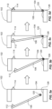
- FIG. 5a to 5d there is shown steps for installing the elevator car operating panel 106 of Figures 1 and 2 in the elevator cab 102.
- a first step as shown in Figure 5a , the elevator car operating panel 106 is positioned inside the elevator cab 102 with the rear surface 110 facing the elevator cab wall 104 that includes the second connector portion 114.
- the hinge rod 120 forming the first part of the hinge mechanism is coupled with the second part of the hinge mechanism in the elevator cab wall 104.
- the first part of the hinge mechanism is provided on a lower edge of the elevator car operating panel 106.
- the lower edge of the elevator car operating panel 106 is coupled to the elevator cab wall 104 first via the hinge mechanism.
- the elevator car operating panel 106 is hinged with respect to the elevator cab wall 104, such that an upper edge of the elevator car operating panel 106 moves towards the elevator cab wall 104.
- a fourth step the hinging of the elevator car operating panel 106 continues until the first connector portion 112 cooperates with the second connector portion 114 to form the electrical connection as shown in Figure 5d .
- the first connector portion 112 is inserted into the second connector portion 114 as the elevator car operating panel 106 hinges closer to the elevator cab wall 104.
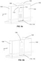
- FIGs 6a and 6b illustrate an external view of the elevator cab 102.
- the elevator cab wall 104 onto which the elevator car operating panel 106 is mounted, is shown in a translucent view, so that the elevator car operating panel 106 can be seen.
- the elevator cab wall 104 may be opaque and that the elevator car operating panel 106 may not be visible from the outside of the elevator cab 102.
- the first connector portion 112 is provided at the upper edge of the elevator car operating panel 106, distal from the first part of the hinge mechanism. This may be advantageous in that it may enable the first connector portion 112 to more accurately align with the second connector portion 114. This is because at the point where the first and second connector portion 112, 114 contact during hinging of the elevator car operating panel 106, the elevator car operating panel 106 is close to vertical so that the first and second connector portions 112, 114 are almost axially aligned. This helps to enable easier insertion of first connector portion 112 into the second connector portion 114.
- FIG. 7 illustrates an example hinge mechanism 132 in further detail.
- the first part of the hinge mechanism 132 is a hinge rod 120, which is coupled to a rear surface of the elevator car operating panel 106, for example via coupling members provided at each end of the hinge rod 120.
- the second part of the hinge mechanism 132 includes a plurality of hook portions 122.
- Each hook portion 122 includes a fixing part for fixing to the elevator cab wall 104, for example, via one or more screws, and a hook part that is configured to receive the hinge rod 120.
- the hook part may aptly be configured to be resilient such that the hinge rod may snap fit into the hook part. This may help with easier installation by securely locating the hinge rod 120 into the hook portions 122 before hinging the elevator car operating panel 106 into the final position.
- the first part of the hinge mechanism 132 Whilst the first part of the hinge mechanism 132 is shown on a lower edge of the elevator car operating panel 106 in the example of Figures 1 to 7 , in other examples, the first part of the hinge mechanism 132 may be provided along any other edge of the elevator car operating panel 106. For example, the first part of the hinge mechanism 132 may be provided along one of the top, bottom and side edges of the elevator car operating panel 106. In the example shown in Figures 8a, 8b and 9 , the hinge mechanism 132 is provided along a side edge of the elevator car operating panel 106. Apart from its position, the hinge mechanism 132 of Figures 8a, 8b and 9 is substantially identical to that already described with reference to Figure 7 and will not be described again in detail.
- first connector portion 112 and second connector portion 114 in further detail.
- the first connector portion 112 is positioned on a rear surface 110 of the elevator car operating panel 106.
- the first connector portion 112 is a male connector portion and therefore extends outwardly from the rear surface 110 of the elevator car operating panel 106.
- the second connector portion 114 is provided in the elevator cab wall 104.
- the second connector portion 114 is a female connector portion 104 and in this example is recessed into the elevator cab wall 104.
- first connector portion 112 may include a plurality of receptacle contacts 128 and the second connector portion 114 may include a plurality of corresponding pin contacts 130.
- the pin contacts 130 may alternatively be provided as part of the first connector portion 112 (male connector portion) and the receptacle contacts 128 may be provided as part of the second connector portion 114 (female connector portion).
- FIG. 11, 12a and 12b there is shown an elevator car assembly including an elevator car operating panel 106 and elevator cab wall 104 with an alternative mechanical coupling 116, corresponding coupling 118, first connector portion 112, and second connector portion 114.
- the remaining elements of the example of Figures 11, 12a and 12b are substantially identical to those described previously and will not be described again in detail.
- the mechanical coupling 116 and corresponding coupling 118 are illustrated in further detail in Figures 13a and 13b .
- the mechanical coupling 116 includes first and second spaced apart hooks extending from the rear surface of the elevator car operating panel 106.
- the elevator cab wall 104 includes the corresponding coupling 118, which includes first and second spaced apart slots or apertures. The first and second hooks are configured to engage a lower edge of a corresponding slot or aperture, to thereby hang the elevator car operating panel 106 onto the elevator cab wall 104.
- the elevator car operating panel 106 is first positioned with respect to the elevator cab wall 104 such that the first and second hooks slot into an upper region of the corresponding first and second slots or apertures.
- the elevator car operating panel 106 is then pushed in a generally downward direction until the first and second hooks engage with the lower edge of the first and second slots or apertures.
- the first and second connector portions 112, 114 are configured to form a sliding electrical connection. That is, the first connector portion 112 is configured to slide relative to the second connector portion 114 whilst maintaining electrical connection between the pin contact 130 and the receptacle contact 128.
- the first connector portion 112 and the second connector portion may be elongated in the vertical direction such that the first connector portion 112 may be located over the second connector portion 114 and is configured to slide over the second connector portion 114 as the elevator car operating panel 106 is pushed downwardly to engage the first and second hooks with the lower edge of the first and second slots or apertures. In this way, the first and second connector portions 112, 114 may form an electrical connection by a push fit and slide action.
- the elevator car operating panel 106 may additionally be fixed into the elevator cab wall 104 using one or more securing elements as described above.
- any of the example elevator car assemblies described herein may include one or more elevator car operating panels according to any of the examples described herein secured to one or more of the elevator cab walls.
- each elevator car operating panel may include a user interface having the same or different elevator controls as the other elevator car operating panel(s).
- the easily replaceable elevator car operating panel described herein further simplifies maintenance and troubleshooting procedures since the elevator car operating panel can be quickly replaced with a temporary elevator car operating panel whilst the original elevator car operating panel is being serviced, maintained or repaired. This enables the elevator to continue operating during repair of the elevator car operating panel, thereby minimizing inconvenience to users.
- the elevator car operating panel as described herein is more field friendly since change of the elevator car operating panel can be carried out entirely from within the elevator cab. There is no need for maintenance personnel to go on top of the elevator car or on a working platform in order to connect or disconnect wiring from the elevator car operating panel.
Landscapes
- Engineering & Computer Science (AREA)
- Automation & Control Theory (AREA)
- Civil Engineering (AREA)
- Mechanical Engineering (AREA)
- Structural Engineering (AREA)
- Computer Networks & Wireless Communication (AREA)
- Cage And Drive Apparatuses For Elevators (AREA)
Abstract
Description
- This disclosure relates to an elevator car operating panel, an elevator cab and an elevator car assembly including an elevator cab and an elevator car operating panel.
- Elevator cars generally include an elevator car operating panel ("COP"), which is provided inside the elevator car. The COP may include various electronic components, for example buttons for selecting a desired landing floor, a display screen, an emergency stop switch, an alarm button, door open and close buttons and maintenance switches.
- Each of the electronic components generally require manual wiring between the COP and a junction box, which is typically situated on top of the elevator car. This manual wiring leads to complex maintenance procedures that are difficult to carry out in situ. Furthermore, it is difficult and time consuming to update the COP, for example to add additional features, replace existing components, or provide an aesthetic update, and such updates often require a complete replacement of the elevator car enclosure, which can be costly.
- The elevator car operating panel and elevator car assembly according to the present disclosure seeks to address one or more of these shortcomings.
- According to a first aspect of this disclosure there is provided an elevator car assembly comprising:
- an elevator car operating panel comprising a user interface on a front surface and a first connector portion on a rear surface; and
- an elevator cab comprising a plurality of walls comprising at least one elevator cab wall for mounting the elevator car operating panel thereon, the at least one elevator cab wall comprising a second connector portion;
- wherein the first connector portion is configured to form a releasable electrical connection with the second connector portion.
- Optionally, one of the first and second connector portion is a male connector portion and the other of the first and second connector portion is a female connector portion.
- Optionally, the first connector portion is configured for insertion into the second connector portion.
- Optionally, the first connector portion comprises at least one pin contact and the second connector portion comprises at least one receptacle contact configured to cooperate with the at least one pin contact.
- Optionally, the first connector portion comprises at least one receptacle contact and the second connector portion comprises at least one pin contact configured to cooperate with the at least one receptacle contact.
- Optionally, the first connector portion and the second connector portion are configured to push fit together.
- Optionally, the first connector portion is further configured to form a releasable data connection with the second connector portion.
- Optionally, the elevator car operating panel comprises a printed circuit board between the front surface and the rear surface, and the first connector portion is electrically coupled to the printed circuit board.
- Optionally, the second connector portion is electrically coupled to circuitry on the elevator cab.
- Optionally, the elevator car operating panel is configured for releasably mounting onto the at least one elevator cab wall.
- Optionally, the elevator car operating panel comprises a mechanical coupling configured to releasably couple with a corresponding coupling on the at least one elevator cab wall.
- Optionally, the mechanical coupling comprises a first part of a hinge mechanism, and the corresponding coupling comprises a second part of a hinge mechanism, wherein the first part of the hinge mechanism is configured to cooperate with the second part of the hinge mechanism such that the elevator car operating panel hinges with respect to the at least one elevator cab wall.
- Optionally, the elevator car assembly further comprises at least one securing element configured to secure the elevator car operating panel in a mounted position with respect to the at least one elevator cab wall.
- Optionally, the user interface comprises at least one elevator control comprising at least one of a switch, a button, and a display, each accessible through or disposed upon the front surface of the elevator car operating panel.
- According to a second aspect of this disclosure, there is provided an elevator cab comprising:
- a plurality of elevator cab walls comprising at least one elevator cab wall for mounting an elevator car operating panel thereon, the at least one elevator cab wall comprising a second connector portion;
- wherein the second connector portion is configured to form a releasable electrical connection with a first connector portion provided on a rear surface of the elevator car operating panel.
- According to a third aspect of this disclosure, there is provided an elevator car operating panel comprising:
a user interface on a front surface of the elevator car operating panel and a first connector portion on a rear surface of the elevator car operating panel;
wherein the first connector portion is configured to form a releasable electrical connection with a second connector portion provided on at least one wall of an elevator cab. - Various examples described herein advantageously provide an elevator car operating panel that is simple to install and easy to replace compared to existing elevator car operating panels.
- Some examples of this disclosure will now be described, by way of example only, with reference to the accompanying drawings, in which:
-
Figure 1 shows an elevator car assembly; -
Figure 2 shows a further example of an elevator car assembly; -
Figure 3 shows a sectional side view of an elevator car operating panel; -
Figure 4 shows a sectional side view of an elevator cab wall; -
Figures 5a to 5d show steps for mounting the elevator car operating panel ofFigure 3 onto the elevator cab wall ofFigure 4 ; -
Figures 6a and 6b show an exterior view of another example of an elevator cab with an elevator car operating panel being installed; -
Figure 7 shows a detailed view of the mechanical coupling of the example ofFigures 6a and 6b ; -
Figures 8a and 8b show an exterior view of yet another example of an elevator cab with an elevator car operating panel being installed; -
Figure 9 shows a detailed view of the mechanical coupling of the example ofFigures 8a and 8b ; -
Figures 10a and 10b show a detailed view of the electrical coupling of the example ofFigures 6a and 6b andFigures 8a and 8b ; -
Figure 11 shows an exterior view of another example of an elevator cab; -
Figure 12a shows the elevator cab ofFigure 11 with an elevator car operating panel installed; -
Figure 12b shows a detailed view of the electrical coupling ofFigure 12a ; and -
Figures 13a and 13b show a detailed view of the mechanical coupling between the elevator cab wall and the elevator car operating panel of the example ofFigures 12a and 12b . - In the drawings, like reference numerals refer to like parts.
-
Figure 1 illustrates anelevator car assembly 100. Theelevator car assembly 100 includes anelevator cab 102 including a plurality ofwalls 104. For illustration purposes, theelevator cab 102 ofFigure 1 is shown with an open side, though it will be appreciated that theelevator cab 102 will generally include a further wall and elevator doors for access into theelevator cab 102. For example, access to theelevator cab 102 may be provided in the direction of the arrow A through sliding doors provided in place of at least part of theelevator cab wall 104. - The
elevator car assembly 100 further includes an elevatorcar operating panel 106, which is mounted onto one of the plurality ofelevator cab walls 104. The elevatorcar operating panel 106 includes auser interface 124, which may include various elevator controls. The elevator controls may, for example, include buttons to select a destination floor, maintenance switches, and a display which may display information to the user such as a selected destination floor, a current position floor, and a direction of movement of theelevator car assembly 100. - In this example, the elevator
car operating panel 106 is sized to extend over a portion of one of the plurality ofelevator cab walls 104, extending from afloor 126 of theelevator cab 102 to a ceiling of theelevator cab 102. In other examples, the elevatorcar operating panel 106 may be sized to extend over the entirety of the width of theelevator cab wall 104. In other examples, such as that shown inFigure 2 , the elevatorcar operating panel 106 may be configured to extend over a portion of the height and width of theelevator cab wall 104. It will be appreciated that the elevatorcar operating panel 106 may be configured with a different size and shape according to the number and type of elevator controls included on the elevatorcar operating panel 106 and the aesthetic requirements of theelevator cab 102. -
Figures 3 and 4 respectively show schematic views of a sectional side view of an elevatorcar operating panel 106 and anelevator cab wall 104 to which it is mounted. The elevatorcar operating panel 106 includes afront surface 108 and arear surface 110. Theuser interface 124 is provided on thefront surface 108 such that each of the elevator controls may be accessible through or disposed upon thefront surface 108 of the elevatorcar operating panel 106. The elevatorcar operating panel 106 further includes afirst connector portion 112 provided on therear surface 110. - The
elevator cab wall 104, onto which the elevatorcar operating panel 106 is mounted, includes asecond connector portion 114. Thefirst connector portion 112 is configured to form a releasable electrical connection with thesecond connector portion 114. That is, thefirst connector portion 112 is configured to cooperate with thesecond connector portion 114 to form the releasable electrical connection. - The
elevator control panel 106 may include a printed circuit board between thefront surface 108 and therear surface 110. Thefirst connector portion 112 may be electrically coupled to the printed circuit board. In one example, thefirst connector portion 112 may be a male connector soldered onto the printed circuit board. Thesecond connector portion 114 is electrically coupled to circuitry on or in theelevator cab 102. In one example thesecond connector portion 114 may be a female wire connector configured to connect with wires on or in theelevator cab 102. - In some examples the
first connector portion 112 andsecond connector portion 114 are further configured to form a data connection for transfer of data. This may be utilised for communication of the elevatorcar operating panel 106 with an elevator controller, for example. In other examples, a third connector portion may be provided on the elevatorcar operating panel 106 and a fourth connector portion may be provided on theelevator cab wall 104. The third and fourth connector portions may be configured to cooperate to form a dedicated data connection that is independent of the electrical connection. This may be advantageous as a separate data connection may provide higher speed data transfer. It will be appreciated that the third and fourth connector portions may be configured similarly to the first andsecond connector portions - One of the first and
second connector portion second connector portion - In this example, the
first connector portion 112 is a male connector portion and thesecond connector portion 114 is a female connector portion. In other examples, thefirst connector portion 112 may be a female connector portion and thesecond connector portion 114 may be a male connector portion. - The
first connector portion 112 is configured such that it can be inserted or plugged into thesecond connector portion 114 to form the electrical connection. Thefirst connector portion 112 and thesecond connector portion 114 may be configured to form a push fit connection. In this way, during installation or maintenance it is possible to simply push together the first andsecond connector portions car operating panel 106 with theelevator cab wall 104. - In one example the
first connector portion 112 may include a plurality of pin contacts and thesecond connector portion 114 may include a plurality of receptacle contacts configured to cooperate with the plurality of pin contacts. The pin contacts are configured to be slidably received in the receptacle contacts such that a releasable electrical connection may be formed. - It will be appreciated by those skilled in the art that various connectors configured for transfer of power and/or data may be suitable for use as the first and
second connector portions car operating panel 106 may be utilised. In some examples, a connector configured to provide both electrical connection and data connection may be used. The first connector portion may include both electrical contacts and data contacts configured to engage with corresponding contacts on the second connector portion. - The elevator
car operating panel 106 may further be configured for releasably mounting onto theelevator cab wall 104. For example, the elevatorcar operating panel 106 may include amechanical coupling 116 configured to releasably couple with acorresponding coupling 118 on theelevator cab wall 104. In this way, the elevatorcar operating panel 106 can be relatively easily installed, removed and replaced. - In this example, the
mechanical coupling 116 includes a first part of a hinge mechanism. In this example, the first part of the hinge mechanism is ahinge rod 120 positioned along a lower edge of the elevatorcar operating panel 106. The correspondingcoupling 118 comprises a second part of the hinge mechanism. In this example, the second part of the hinge mechanism is a longitudinal groove orrecess 122 configured to receive thehinge rod 120 of the first part of the hinge mechanism. The first part of the hinge mechanism is configured to cooperate with the second part of the hinge mechanism such that the elevatorcar operating panel 106 hinges with respect to theelevator cab wall 104. In this example, when thehinge rod 120 engages with the groove orrecess 122, the elevatorcar operating panel 106 hinges about an axis of thehinge rod 120. - The
elevator car assembly 100 may further include at least one securing element configured to secure the elevatorcar operating panel 106 to theelevator cab wall 104. The at least one securing element may include one or more screws, bolts, or locks. The screws, bolts or locks may be positioned distal from the mechanical coupling and may secure theelevator operating panel 106 to theelevator cab wall 104. The securing elements may aptly be configured to prevent unauthorised removal of the elevatorcar operating panel 106 from theelevator cab wall 104. For example, the securing elements may be tamper proof. For example, the securing elements may require a unique key or tooling to release the securing element and remove the elevatorcar operating panel 106 from theelevator cab wall 104. - Turning now to
Figures 5a to 5d , there is shown steps for installing the elevatorcar operating panel 106 ofFigures 1 and 2 in theelevator cab 102. In a first step, as shown inFigure 5a , the elevatorcar operating panel 106 is positioned inside theelevator cab 102 with therear surface 110 facing theelevator cab wall 104 that includes thesecond connector portion 114. - In a second step, as shown in
Figure 5b , thehinge rod 120 forming the first part of the hinge mechanism is coupled with the second part of the hinge mechanism in theelevator cab wall 104. In this example, the first part of the hinge mechanism is provided on a lower edge of the elevatorcar operating panel 106. As such, the lower edge of the elevatorcar operating panel 106 is coupled to theelevator cab wall 104 first via the hinge mechanism. - In a third step, as shown in
Figure 5c , the elevatorcar operating panel 106 is hinged with respect to theelevator cab wall 104, such that an upper edge of the elevatorcar operating panel 106 moves towards theelevator cab wall 104. - In a fourth step, the hinging of the elevator
car operating panel 106 continues until thefirst connector portion 112 cooperates with thesecond connector portion 114 to form the electrical connection as shown inFigure 5d . In this example, thefirst connector portion 112 is inserted into thesecond connector portion 114 as the elevatorcar operating panel 106 hinges closer to theelevator cab wall 104. - A similar hinging mechanism can also be seen in
Figures 6a and 6b , which illustrate an external view of theelevator cab 102. In this example, theelevator cab wall 104, onto which the elevatorcar operating panel 106 is mounted, is shown in a translucent view, so that the elevatorcar operating panel 106 can be seen. However, it will be appreciated that theelevator cab wall 104 may be opaque and that the elevatorcar operating panel 106 may not be visible from the outside of theelevator cab 102. - In the example shown, the
first connector portion 112 is provided at the upper edge of the elevatorcar operating panel 106, distal from the first part of the hinge mechanism. This may be advantageous in that it may enable thefirst connector portion 112 to more accurately align with thesecond connector portion 114. This is because at the point where the first andsecond connector portion car operating panel 106, the elevatorcar operating panel 106 is close to vertical so that the first andsecond connector portions first connector portion 112 into thesecond connector portion 114. -
Figure 7 illustrates anexample hinge mechanism 132 in further detail. As shown, the first part of thehinge mechanism 132 is ahinge rod 120, which is coupled to a rear surface of the elevatorcar operating panel 106, for example via coupling members provided at each end of thehinge rod 120. - The second part of the
hinge mechanism 132 includes a plurality ofhook portions 122. Eachhook portion 122 includes a fixing part for fixing to theelevator cab wall 104, for example, via one or more screws, and a hook part that is configured to receive thehinge rod 120. The hook part may aptly be configured to be resilient such that the hinge rod may snap fit into the hook part. This may help with easier installation by securely locating thehinge rod 120 into thehook portions 122 before hinging the elevatorcar operating panel 106 into the final position. - Whilst the first part of the
hinge mechanism 132 is shown on a lower edge of the elevatorcar operating panel 106 in the example ofFigures 1 to 7 , in other examples, the first part of thehinge mechanism 132 may be provided along any other edge of the elevatorcar operating panel 106. For example, the first part of thehinge mechanism 132 may be provided along one of the top, bottom and side edges of the elevatorcar operating panel 106. In the example shown inFigures 8a, 8b and 9 , thehinge mechanism 132 is provided along a side edge of the elevatorcar operating panel 106. Apart from its position, thehinge mechanism 132 ofFigures 8a, 8b and 9 is substantially identical to that already described with reference toFigure 7 and will not be described again in detail. - Referring now to
Figures 10a and 10b there is illustrated afirst connector portion 112 andsecond connector portion 114 in further detail. As shown, in this example, thefirst connector portion 112 is positioned on arear surface 110 of the elevatorcar operating panel 106. Thefirst connector portion 112 is a male connector portion and therefore extends outwardly from therear surface 110 of the elevatorcar operating panel 106. Thesecond connector portion 114 is provided in theelevator cab wall 104. Thesecond connector portion 114 is afemale connector portion 104 and in this example is recessed into theelevator cab wall 104. - The
first connector portion 112 includes areceptacle contact 128 at an end distal from therear surface 110 of the elevatorcar operating panel 106. Thesecond connector portion 114 includes apin contact 130 extending from a base of the recess of thesecond connector portion 114 partly towards the surface of theelevator cab wall 104. As thefirst connector portion 112 couples with thesecond connector portion 114, the male connector portion is inserted into the female connector portion and thereceptacle contact 128 receives thepin contact 130 to form the electrical connection. - Whilst one
receptacle contact 128 and onepin contact 130 are shown in the example ofFigure 10a and 10b , it will be appreciated that thefirst connector portion 112 may include a plurality ofreceptacle contacts 128 and thesecond connector portion 114 may include a plurality ofcorresponding pin contacts 130. Thepin contacts 130 may alternatively be provided as part of the first connector portion 112 (male connector portion) and thereceptacle contacts 128 may be provided as part of the second connector portion 114 (female connector portion). - Referring now to
Figures 11, 12a and 12b , there is shown an elevator car assembly including an elevatorcar operating panel 106 andelevator cab wall 104 with an alternativemechanical coupling 116, correspondingcoupling 118,first connector portion 112, andsecond connector portion 114. The remaining elements of the example ofFigures 11, 12a and 12b are substantially identical to those described previously and will not be described again in detail. - The alternative
mechanical coupling 116 andcorresponding coupling 118 are illustrated in further detail inFigures 13a and 13b . In this example, themechanical coupling 116 includes first and second spaced apart hooks extending from the rear surface of the elevatorcar operating panel 106. Theelevator cab wall 104 includes thecorresponding coupling 118, which includes first and second spaced apart slots or apertures. The first and second hooks are configured to engage a lower edge of a corresponding slot or aperture, to thereby hang the elevatorcar operating panel 106 onto theelevator cab wall 104. - As shown in
Figure 13a , during installation the elevatorcar operating panel 106 is first positioned with respect to theelevator cab wall 104 such that the first and second hooks slot into an upper region of the corresponding first and second slots or apertures. The elevatorcar operating panel 106 is then pushed in a generally downward direction until the first and second hooks engage with the lower edge of the first and second slots or apertures. - In this example, as shown in
Figure 12b the configuration of the electrical coupling is reversed compared to the example ofFigure 8b . That is, thefirst connector portion 112 is a female connector portion including apin contact 130 and thesecond connector portion 114 is a male connector portion including areceptacle contact 128. - In order to allow for the elevator
car operating panel 106 to be mounted to theelevator cab wall 104 via the first and second hooks and slots, the first andsecond connector portions first connector portion 112 is configured to slide relative to thesecond connector portion 114 whilst maintaining electrical connection between thepin contact 130 and thereceptacle contact 128. For example, thefirst connector portion 112 and the second connector portion may be elongated in the vertical direction such that thefirst connector portion 112 may be located over thesecond connector portion 114 and is configured to slide over thesecond connector portion 114 as the elevatorcar operating panel 106 is pushed downwardly to engage the first and second hooks with the lower edge of the first and second slots or apertures. In this way, the first andsecond connector portions - The elevator
car operating panel 106 may additionally be fixed into theelevator cab wall 104 using one or more securing elements as described above. - It will be appreciated that any of the example elevator car assemblies described herein may include one or more elevator car operating panels according to any of the examples described herein secured to one or more of the elevator cab walls. In the elevator cab of an elevator car assembly including a plurality of elevator car operating panels, each elevator car operating panel may include a user interface having the same or different elevator controls as the other elevator car operating panel(s).
- It will be appreciated that any of the elevator car operating panels described herein may include a plurality of electrical connections and a plurality of data connections. The data connection may be configured similarly to any of the electrical connections described herein. It will also be appreciated that a single first and second connector portion may simultaneously provide both an electrical connection and a data connection.
- Whilst in some of the examples described herein, the first connector portion is provided at an upper edge of the elevator car operating panel, it will be appreciated that the position of the first connector portion may be on any portion of the rear surface of the elevator car operating panel and is not restricted to the upper edge. Similarly, the second connector portion may be positioned on any portion of the elevator cab wall to correspond to the position of the first connector portion on the elevator car operating panel.
- Various examples described herein advantageously provide an elevator car operating panel that can be relatively easily installed, removed, and replaced, thereby forming a "plug and play" type interface between the elevator car operating panel and the elevator cab. The elevator car operating panel can be delivered as a stand-alone item without the need to wire multiple cables and without the need for any specific tooling.
- The elevator car operating panel described herein enables simple replacement of the elevator car operating panel, for example allowing various aesthetic updates to the elevator cab without the need for specific maintenance personnel to carry out the update. The elevator car operating panel described herein thereby allows for more time efficient elevator cab updates and aesthetic refresh than prior art elevator car operating panels.
- The easily replaceable elevator car operating panel described herein further simplifies maintenance and troubleshooting procedures since the elevator car operating panel can be quickly replaced with a temporary elevator car operating panel whilst the original elevator car operating panel is being serviced, maintained or repaired. This enables the elevator to continue operating during repair of the elevator car operating panel, thereby minimizing inconvenience to users.
- The elevator car operating panel as described herein is more field friendly since change of the elevator car operating panel can be carried out entirely from within the elevator cab. There is no need for maintenance personnel to go on top of the elevator car or on a working platform in order to connect or disconnect wiring from the elevator car operating panel.
- It will be appreciated by those skilled in the art that the disclosure has been illustrated by describing one or more examples thereof, but is not limited to these examples; many variations and modifications are possible, within the scope of the accompanying claims.
Claims (15)
- An elevator car assembly (100) comprising:an elevator car operating panel (106) comprising a user interface (124) on a front surface (108) and a first connector portion (112) on a rear surface (110); andan elevator cab (102) comprising a plurality of walls (104) comprising at least one elevator cab wall (104) for mounting the elevator car operating panel (106) thereon, the at least one elevator cab wall (104) comprising a second connector portion (114);wherein the first connector portion (112) is configured to form a releasable electrical connection with the second connector portion (114).
- An elevator car assembly (100) according to claim 1, wherein one of the first and second connector portion (112, 114) is a male connector portion and the other of the first and second connector portion (112, 114) is a female connector portion.
- An elevator car assembly (100) according to claim 1 or claim 2, wherein the first connector portion (112) is configured for insertion into the second connector portion (114).
- An elevator car assembly (100) according to any preceding claim, wherein the first connector portion (112) comprises at least one pin contact (130) and the second connector portion (114) comprises at least one receptacle contact (128) configured to cooperate with the at least one pin contact (130), or wherein the first connector portion (112) comprises at least one receptacle contact (128) and the second connector portion (114) comprises at least one pin contact (130) configured to cooperate with the at least one receptacle contact (128).
- An elevator car assembly (100) according to any preceding claim, wherein the first connector portion (112) and the second connector portion (114) are configured to push fit together.
- An elevator car assembly (100) according to any preceding claim, wherein the first connector portion (112) is further configured to form a releasable data connection with the second connector portion (114).
- An elevator car assembly (100) according to any preceding claim, wherein the elevator car operating panel (106) comprises a printed circuit board between the front surface (108) and the rear surface (110), and the first connector portion (112) is electrically coupled to the printed circuit board.
- An elevator car assembly (100) according to any preceding claim, wherein the second connector portion (114) is electrically coupled to circuitry on the elevator cab (102).
- An elevator car assembly (100) according to any preceding claim, wherein the elevator car operating panel (106) is configured for releasably mounting onto the at least one elevator cab wall (104).
- An elevator car assembly (100) according to any preceding claim, wherein the elevator car operating panel (106) comprises a mechanical coupling (116) configured to releasably couple with a corresponding coupling (118) on the at least one elevator cab wall (104).
- An elevator car assembly (100) according to claim 10, wherein the mechanical coupling (116) comprises a first part of a hinge mechanism, and the corresponding coupling comprises a second part of a hinge mechanism, wherein the first part of the hinge mechanism is configured to cooperate with the second part of the hinge mechanism such that the elevator car operating panel (106) hinges with respect to the at least one elevator cab wall (104).
- An elevator car assembly (100) according to any preceding claim, further comprising at least one securing element configured to secure the elevator car operating panel (106) in a mounted position with respect to the at least one elevator cab wall (104).
- An elevator car assembly (100) according to any preceding claim, wherein the user interface (124) comprises at least one elevator control comprising at least one of a switch, a button, and a display, each accessible through or disposed upon the front surface (108) of the elevator car operating panel (106).
- An elevator cab (102) comprising:a plurality of elevator cab walls (104) comprising at least one elevator cab wall (104) for mounting an elevator car operating panel (106) thereon, the at least one elevator cab wall (104) comprising a second connector portion (114);wherein the second connector portion (114) is configured to form a releasable electrical connection with a first connector portion (112) provided on a rear surface (110) of the elevator car operating panel (106).
- An elevator car operating panel (106) comprising:a user interface (124) on a front surface (108) of the elevator car operating panel (106) and a first connector portion (112) on a rear surface (110) of the elevator car operating panel (106);wherein the first connector portion (112) is configured to form a releasable electrical connection with a second connector portion (114) provided on at least one wall (104) of an elevator cab (102).
Priority Applications (3)
| Application Number | Priority Date | Filing Date | Title |
|---|---|---|---|
| EP22305738.1A EP4279433A1 (en) | 2022-05-19 | 2022-05-19 | Elevator car assembly |
| US17/984,764 US20230373752A1 (en) | 2022-05-19 | 2022-11-10 | Elevator car assembly |
| CN202211455313.7A CN117088206B (en) | 2022-05-19 | 2022-11-21 | Elevator car assembly |
Applications Claiming Priority (1)
| Application Number | Priority Date | Filing Date | Title |
|---|---|---|---|
| EP22305738.1A EP4279433A1 (en) | 2022-05-19 | 2022-05-19 | Elevator car assembly |
Publications (1)
| Publication Number | Publication Date |
|---|---|
| EP4279433A1 true EP4279433A1 (en) | 2023-11-22 |
Family
ID=81975357
Family Applications (1)
| Application Number | Title | Priority Date | Filing Date |
|---|---|---|---|
| EP22305738.1A Pending EP4279433A1 (en) | 2022-05-19 | 2022-05-19 | Elevator car assembly |
Country Status (3)
| Country | Link |
|---|---|
| US (1) | US20230373752A1 (en) |
| EP (1) | EP4279433A1 (en) |
| CN (1) | CN117088206B (en) |
Citations (3)
| Publication number | Priority date | Publication date | Assignee | Title |
|---|---|---|---|---|
| JP2015218028A (en) * | 2014-05-16 | 2015-12-07 | 東芝エレベータ株式会社 | Elevator control panel |
| CN212863662U (en) * | 2020-06-24 | 2021-04-02 | 英沃电梯有限公司 | Modularized elevator calling board |
| CN215101301U (en) * | 2021-07-08 | 2021-12-10 | 日立电梯(中国)有限公司 | Integrated control box in elevator car |
Family Cites Families (3)
| Publication number | Priority date | Publication date | Assignee | Title |
|---|---|---|---|---|
| WO2017063702A1 (en) * | 2015-10-15 | 2017-04-20 | Otis Elevator Company | Elevator car panel |
| CN110831879B (en) * | 2017-06-27 | 2021-02-23 | 因温特奥股份公司 | Elevator monitored with passengers' smart mobile devices |
| DK3524560T3 (en) * | 2018-02-13 | 2021-03-15 | Kone Corp | ELEVATOR WITH BACKUP POWER SUPPLY |
-
2022
- 2022-05-19 EP EP22305738.1A patent/EP4279433A1/en active Pending
- 2022-11-10 US US17/984,764 patent/US20230373752A1/en active Pending
- 2022-11-21 CN CN202211455313.7A patent/CN117088206B/en active Active
Patent Citations (3)
| Publication number | Priority date | Publication date | Assignee | Title |
|---|---|---|---|---|
| JP2015218028A (en) * | 2014-05-16 | 2015-12-07 | 東芝エレベータ株式会社 | Elevator control panel |
| CN212863662U (en) * | 2020-06-24 | 2021-04-02 | 英沃电梯有限公司 | Modularized elevator calling board |
| CN215101301U (en) * | 2021-07-08 | 2021-12-10 | 日立电梯(中国)有限公司 | Integrated control box in elevator car |
Also Published As
| Publication number | Publication date |
|---|---|
| CN117088206A (en) | 2023-11-21 |
| US20230373752A1 (en) | 2023-11-23 |
| CN117088206B (en) | 2026-03-03 |
Similar Documents
| Publication | Publication Date | Title |
|---|---|---|
| US7489522B2 (en) | Case for electronic equipment and communication device | |
| US6091023A (en) | Enclosure for interfacing electrical and control or communication devices | |
| US7525809B2 (en) | Isolated control and network wireway for motor control center | |
| CN115804248A (en) | Modular electrical accessory | |
| US20220302645A1 (en) | Unlocking structure and operating method for pluggable modules | |
| US20160255421A1 (en) | Door module and uses thereof | |
| CN1259782A (en) | Plane-end embedding type terminal device having highly adjustable data socket erection frame | |
| US8602816B2 (en) | Connector device for electronic modules in automation systems | |
| US20210273420A1 (en) | Safety switch feature for an electronic device | |
| US20230373752A1 (en) | Elevator car assembly | |
| US5081809A (en) | Demountable wall panelling | |
| US11928955B2 (en) | Safety disconnect mechanism with integrated illumination for electronic devices | |
| CN208806410U (en) | A kind of wiring construction and its power equipment | |
| CN216583622U (en) | Control cabinet for elevator and elevator | |
| CN216850508U (en) | Orbital seal structure and power distribution device | |
| US9948073B2 (en) | Auxiliary compartment for a switchgear system | |
| US5789908A (en) | Lighting dimmer rack with removable connector modules | |
| CN210725720U (en) | Switch box and signal control cabinet with same | |
| US7238882B2 (en) | Low voltage door switch | |
| CN113788378A (en) | Control cabinet for elevator and elevator | |
| CN206844866U (en) | A kind of lock control devices and the cabinet using the lock control devices | |
| EP2869159A1 (en) | Display device for an aircraft | |
| CN214754529U (en) | Open wiring duct system capable of safely replacing fetched potential | |
| JP2588913Y2 (en) | Outlet box mounting device | |
| KR200213775Y1 (en) | Separation devece of control unit from motor control center |
Legal Events
| Date | Code | Title | Description |
|---|---|---|---|
| PUAI | Public reference made under article 153(3) epc to a published international application that has entered the european phase |
Free format text: ORIGINAL CODE: 0009012 |
|
| STAA | Information on the status of an ep patent application or granted ep patent |
Free format text: STATUS: THE APPLICATION HAS BEEN PUBLISHED |
|
| AK | Designated contracting states |
Kind code of ref document: A1 Designated state(s): AL AT BE BG CH CY CZ DE DK EE ES FI FR GB GR HR HU IE IS IT LI LT LU LV MC MK MT NL NO PL PT RO RS SE SI SK SM TR |
|
| STAA | Information on the status of an ep patent application or granted ep patent |
Free format text: STATUS: REQUEST FOR EXAMINATION WAS MADE |
|
| 17P | Request for examination filed |
Effective date: 20240508 |
|
| RBV | Designated contracting states (corrected) |
Designated state(s): AL AT BE BG CH CY CZ DE DK EE ES FI FR GB GR HR HU IE IS IT LI LT LU LV MC MK MT NL NO PL PT RO RS SE SI SK SM TR |
|
| STAA | Information on the status of an ep patent application or granted ep patent |
Free format text: STATUS: EXAMINATION IS IN PROGRESS |
|
| 17Q | First examination report despatched |
Effective date: 20250730 |