EP4279372A1 - Subsea configuration for floating structures of an offshore wind farm - Google Patents
Subsea configuration for floating structures of an offshore wind farm Download PDFInfo
- Publication number
- EP4279372A1 EP4279372A1 EP22315109.3A EP22315109A EP4279372A1 EP 4279372 A1 EP4279372 A1 EP 4279372A1 EP 22315109 A EP22315109 A EP 22315109A EP 4279372 A1 EP4279372 A1 EP 4279372A1
- Authority
- EP
- European Patent Office
- Prior art keywords
- peripheral
- wind farm
- offshore wind
- mooring
- mooring lines
- Prior art date
- Legal status (The legal status is an assumption and is not a legal conclusion. Google has not performed a legal analysis and makes no representation as to the accuracy of the status listed.)
- Pending
Links
- 230000002093 peripheral effect Effects 0.000 claims abstract description 87
- 239000013536 elastomeric material Substances 0.000 claims abstract description 8
- 239000000835 fiber Substances 0.000 claims description 8
- 239000000463 material Substances 0.000 claims description 8
- 244000043261 Hevea brasiliensis Species 0.000 claims description 3
- 229920000459 Nitrile rubber Polymers 0.000 claims description 3
- 230000001186 cumulative effect Effects 0.000 claims description 3
- 229920003052 natural elastomer Polymers 0.000 claims description 3
- 229920001194 natural rubber Polymers 0.000 claims description 3
- 229920001084 poly(chloroprene) Polymers 0.000 claims description 3
- 229920002725 thermoplastic elastomer Polymers 0.000 claims description 3
- XLYOFNOQVPJJNP-UHFFFAOYSA-N water Substances O XLYOFNOQVPJJNP-UHFFFAOYSA-N 0.000 description 17
- 230000000694 effects Effects 0.000 description 5
- -1 polypropylene Polymers 0.000 description 4
- 230000000284 resting effect Effects 0.000 description 4
- 238000004873 anchoring Methods 0.000 description 3
- 229920000728 polyester Polymers 0.000 description 3
- 239000003643 water by type Substances 0.000 description 3
- 239000004677 Nylon Substances 0.000 description 2
- 239000004698 Polyethylene Substances 0.000 description 2
- 239000004743 Polypropylene Substances 0.000 description 2
- 230000003373 anti-fouling effect Effects 0.000 description 2
- 239000002184 metal Substances 0.000 description 2
- 229920001778 nylon Polymers 0.000 description 2
- 229920000573 polyethylene Polymers 0.000 description 2
- 229920000098 polyolefin Polymers 0.000 description 2
- 229920001155 polypropylene Polymers 0.000 description 2
- 238000005299 abrasion Methods 0.000 description 1
- 230000001419 dependent effect Effects 0.000 description 1
- 230000007613 environmental effect Effects 0.000 description 1
- 229920000642 polymer Polymers 0.000 description 1
Images


Classifications
-
- B—PERFORMING OPERATIONS; TRANSPORTING
- B63—SHIPS OR OTHER WATERBORNE VESSELS; RELATED EQUIPMENT
- B63B—SHIPS OR OTHER WATERBORNE VESSELS; EQUIPMENT FOR SHIPPING
- B63B21/00—Tying-up; Shifting, towing, or pushing equipment; Anchoring
- B63B21/50—Anchoring arrangements or methods for special vessels, e.g. for floating drilling platforms or dredgers
-
- F—MECHANICAL ENGINEERING; LIGHTING; HEATING; WEAPONS; BLASTING
- F03—MACHINES OR ENGINES FOR LIQUIDS; WIND, SPRING, OR WEIGHT MOTORS; PRODUCING MECHANICAL POWER OR A REACTIVE PROPULSIVE THRUST, NOT OTHERWISE PROVIDED FOR
- F03D—WIND MOTORS
- F03D13/00—Assembly, mounting or commissioning of wind motors; Arrangements specially adapted for transporting wind motor components
- F03D13/20—Arrangements for mounting or supporting wind motors; Masts or towers for wind motors
- F03D13/25—Arrangements for mounting or supporting wind motors; Masts or towers for wind motors specially adapted for offshore installation
- F03D13/256—Arrangements for mounting or supporting wind motors; Masts or towers for wind motors specially adapted for offshore installation on a floating support, i.e. floating wind motors
-
- B—PERFORMING OPERATIONS; TRANSPORTING
- B63—SHIPS OR OTHER WATERBORNE VESSELS; RELATED EQUIPMENT
- B63B—SHIPS OR OTHER WATERBORNE VESSELS; EQUIPMENT FOR SHIPPING
- B63B21/00—Tying-up; Shifting, towing, or pushing equipment; Anchoring
- B63B2021/003—Mooring or anchoring equipment, not otherwise provided for
- B63B2021/005—Resilient passive elements to be placed in line with mooring or towing chains, or line connections, e.g. dampers or springs
-
- B—PERFORMING OPERATIONS; TRANSPORTING
- B63—SHIPS OR OTHER WATERBORNE VESSELS; RELATED EQUIPMENT
- B63B—SHIPS OR OTHER WATERBORNE VESSELS; EQUIPMENT FOR SHIPPING
- B63B35/00—Vessels or similar floating structures specially adapted for specific purposes and not otherwise provided for
- B63B35/44—Floating buildings, stores, drilling platforms, or workshops, e.g. carrying water-oil separating devices
- B63B2035/4433—Floating structures carrying electric power plants
- B63B2035/446—Floating structures carrying electric power plants for converting wind energy into electric energy
-
- F—MECHANICAL ENGINEERING; LIGHTING; HEATING; WEAPONS; BLASTING
- F05—INDEXING SCHEMES RELATING TO ENGINES OR PUMPS IN VARIOUS SUBCLASSES OF CLASSES F01-F04
- F05B—INDEXING SCHEME RELATING TO WIND, SPRING, WEIGHT, INERTIA OR LIKE MOTORS, TO MACHINES OR ENGINES FOR LIQUIDS COVERED BY SUBCLASSES F03B, F03D AND F03G
- F05B2240/00—Components
- F05B2240/90—Mounting on supporting structures or systems
- F05B2240/96—Mounting on supporting structures or systems as part of a wind turbine farm
-
- Y—GENERAL TAGGING OF NEW TECHNOLOGICAL DEVELOPMENTS; GENERAL TAGGING OF CROSS-SECTIONAL TECHNOLOGIES SPANNING OVER SEVERAL SECTIONS OF THE IPC; TECHNICAL SUBJECTS COVERED BY FORMER USPC CROSS-REFERENCE ART COLLECTIONS [XRACs] AND DIGESTS
- Y02—TECHNOLOGIES OR APPLICATIONS FOR MITIGATION OR ADAPTATION AGAINST CLIMATE CHANGE
- Y02E—REDUCTION OF GREENHOUSE GAS [GHG] EMISSIONS, RELATED TO ENERGY GENERATION, TRANSMISSION OR DISTRIBUTION
- Y02E10/00—Energy generation through renewable energy sources
- Y02E10/70—Wind energy
- Y02E10/727—Offshore wind turbines
Definitions
- the present invention relates to a subsea configuration of floating structures for an offshore wind farm. More precisely, the present invention relates to the subsea configuration for floating structures anchored on the seabed for water depths greater than 400 m.
- support structures like jacket structures, for offshore wind turbines.
- Such a support structure rests on the seabed and is fixed to the ground with anchor devices.
- the support structure extends above the sea level to receive a wind turbine mast.
- this support structure is made of one piece and the greater the depth is, the higher the support structure must be.
- the offshore wind turbines are generally not installed on support structures resting on the seabed but are installed on floating structures moored to the seabed with mooring lines.
- two adjacent wind turbines are typically spaced by six to eight times the turbine rotor diameter depending on the considered direction.
- two adjacent wind turbines aligned in the dominant wind direction may be spaced by eight times the turbine rotor diameter in order to minimize the wake effects and in order that the wind turbine placed behind has a greater productivity.
- Two adjacent wind turbines not aligned in the dominant wind direction could be closer to each other for example spaced by six times the turbine rotor diameter in order to maximize the density of wind turbines in the offshore wind farm.
- Standard mooring configuration typically requires a minimum pattern of 1.4 x water depth to 1.8 ⁇ water depth. In deep waters, these mooring footprints could be accommodated by considering different floating structures orientation between adjacent wind turbines to avoid clashes between mooring lines. However, this would lead to a very complex and congested layout and would require additional engineering effort due to the different floating structures orientations to be studied. In order to reduce costs, a mooring layout based on mutualized anchors (between adjacent mooring lines) is known. However, this solution could not be considered in very deep waters where mooring lines would be crossing before reaching the optimized location for this mutualized anchoring point.
- a solution of mooring configuration based on shared mooring lines have been developed for example with shared anchoring points onto the seabed, as describe in document CN210653580 or with shared anchoring point onto common floating buoys, as described in document CN111071400 .
- these solutions provide very low restoring loads to the floating structures when it moves out from the equilibrium position due to external loads, and then leads to very high offsets. These very high offsets would be problematic for the mooring lines themselves and for other equipment linked to the floating structures like electrical inter-array cables.
- One aim of the present invention is to provide an enhanced and cheap mooring configuration for an offshore wind turbine adapted for depths greater than 400 m and having a limited footprint.
- the invention relates to an offshore wind farm comprising at least three floating structures designed to receive a wind turbine, each floating structure comprising at least three mooring lines, each mooring line being attached to a mooring point arranged around said floating structure, the mooring lines facing inward from the offshore wind farm forming the inner mooring lines of the offshore wind farm and the mooring lines facing outward from the offshore wind farm forming the peripheral mooring lines of the offshore wind farm, wherein at least one peripheral mooring line comprises:
- Two adjacent floating structures may have at least one of their peripheral mooring lines having a common junction point above the seabed, this common junction point being attached to a peripheral submerged buoy moored to the seabed, this peripheral submerged buoy comprising a tether moored to the seabed and at least one additional mooring line connecting the peripheral submerged buoy to a mooring point on the seabed.
- the peripheral submerged buoy may comprise two additional mooring lines, each additional mooring line being aligned with a peripheral mooring line attached to the peripheral submerged buoy.
- the peripheral submerged buoy may be moored to the seabed with a flexible tether having a limited height with the seabed.
- the peripheral submerged buoy may be placed at least at 50 m above the seabed.
- the mooring lines may be made of fiber ropes.
- the floating structures may be placed in such a way that the mooring lines form a hexagonal pattern.
- the intermediate segment of the peripheral mooring lines may be able to provide a maximal extension greater than 100 % of the rest length of the intermediate segment, advantageously a maximal extension greater than 300 %;
- the intermediate segment may present a minimal breaking strength greater than 18 MPa, advantageously greater than 25 Mpa.
- the intermediate segment may present a minimal breaking load greater than 400 t, advantageously greater than 1200 t.
- the intermediate segment may present a creep lower than 20%, advantageously lower than 10%.
- the intermediate segment may present a cumulative length lower than 40 m, advantageously lower than 15 m.
- the intermediate segment may be made of a single material.
- the single material may be chosen between:
- the intermediate segment may be a multi-stranded line.
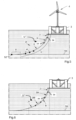
- FIG 1 shows an offshore wind farm 1 comprising at least three floating structures 3 designed to each receive a wind turbine 4.
- Each floating structure 3 comprises at least three mooring lines 5', 5" in order to moor the floating structure 3 to the seabed.
- Each mooring line 5 is attached to a mooring point 51, 52, 53 arranged around the floating structure 3.
- the mooring lines 5', 5" may also be arranged around the floating structure 3 in a "Y" shape in order to maintain the floating structure 3 in any direction on the surface of the sea (see figure 2 ).
- the length of the mooting lines 5', 5" is dependent on their inclination and the water depth.
- the mooring lines facing inward from the offshore wind farm 1 (oriented towards the center or inner side of the wind farm defined by the peripheral floating structures 3) form the inner mooring lines 5' of the offshore wind farm 1 and the mooring lines facing outward from the offshore wind farm 1 (oriented towards the outer side of the wind farm) form the peripheral mooring lines 5" of the offshore wind farm 1.
- the mooring lines 5', 5" may be made of fiber ropes or metallic cables made of metal strands.
- these fiber ropes may be made of polymeric fibers such as polyester, nylon or polyolefin like polypropylene or polyethylene.
- three adjacent floating structures 3 have at least one of their inner mooring lines 5' having a common junction point 51 above the seabed Sb.
- This common junction point 51 is attached to a submerged buoy 7 moored to the seabed Sb.
- the fact that the adjacent floating structures 3 have a common junction point 51 attached to a submerged buoy 7 allows bringing the adjacent floating structures 3 closer to each other.
- the floating structures 3 and the wind turbines 4 could be spaced in an optimum way by, for example, a distance D1 about eight times the turbine rotor diameter for two floating structures 3 aligned in the dominant wind direction W.
- This distance D1 enables minimizing the wake effects and enables the wind turbine 4 placed behind to have a greater productivity.
- Two adjacent floating structures 3 not aligned in the dominant wind direction W may be spaced for example by a distance D2 about six times the turbine rotor diameter in order to maximize the density of wind turbines 4 in the offshore wind farm 1.
- the common junction point 51 may be a point where the inner mooring lines 5' would have crossed each other.
- the depth of the submerged buoy 7 may also be determined by the common junction point 51 where the inner mooring lines 5' would have crossed each other.
- the footprint of the offshore wind farm 1 due to its mooring configuration is limited. Only one mooring point is needed with the submerged buoy 7 instead of three moorings points on the seabed.
- the length of the inner mooring lines 5' attached to the submerged buoy 7 is also reduced which permits a reduction of the costs. This is particularly advantageous for an offshore wind farm 1 installed in greater water depths, for example greater than 400 m.
- the submerged buoy 7 is preferably an equipressure buoy.
- An equipressure buoy allows to reduce the external loads on the buoy once installed at its final depth.
- An equipressure buoy means a buoy where the inner pressure of the buoy is equal to the external pressure of the buoy, here the pressure at the depth the buoy is placed.
- the attachment points of the inner mooring lines 5' to the submerged buoy 7 may be placed below the submerged buoy 7.
- the submerged buoy 7 do not need to be sized up to the minimum breaking load of the inner mooring lines 5'.
- the submerged buoy 7 is moored to the seabed Sb with a flexible tether 71 having a limited height with the seabed Sb.
- This flexible tether 71 could be any means known by the skilled person in this domain.
- the submerged buoy 7 could be moored by at least one cable or chain.
- the submerged buoy 7 is preferably placed at least at 50 m above the seabed Sb. More specifically, the submerged buoy 7 is preferably placed at a maximum depth of 85% of the water depth.
- the flexible tether 71 has a length of at least 15% of the water depth. For example, for a water depth of 600 m, the submerged buoy 7 may be placed at least at a depth of 500 m with flexible tether 71 of 100 m.
- the peripheral mooring lines 5" are directly moored to the seabed Sb. More specifically, the peripheral mooring lines 5" are placed without crossing each other and are moored directly onto the seabed Sb at mooring points 52. The peripheral mooring lines 5" could be moored onto the seabed Sb by any means known by the skilled person in this domain. The fact that the peripheral mooring lines 5" are directly moored to the seabed Sb enables limiting the lateral movements of the offshore wind farm 1 in general and more specifically of the array of floating structures 3.
- Figure 3 shows an offshore wind farm 1 with at least four floating structures 3.
- two adjacent floating structures 3 have at least one of their peripheral mooring lines 5" crossing each other.
- At least one of these peripheral mooring lines comprises a buoyancy element.
- only one of the crossing peripheral mooring lines 5" comprises a buoyancy element in order to pass above the other peripheral mooring line 5" without touching each other.
- This buoyancy element may be associated to an increased anchor radius.
- This buoyancy element could be a sleeve surrounding a portion of the peripheral mooring line 5".
- This buoyancy element could also be directly integrated into a portion the peripheral mooring line 5".
- these two peripheral mooring lines 5" cross each other with a distance about at least 20 m.
- two crossing peripheral mooring lines 5" have a common junction point 53 above the seabed Sb.
- the buoyancy element could be here a peripheral submerged buoy 7' moored to the seabed Sb and to which one the common junction point 53 is attached to.
- This peripheral submerged buoy 7' may comprise a tether 71' (visible in figure 4 ) moored to the seabed Sb and at least one additional mooring line 5′′′ connecting the peripheral submerged buoy 7' to a mooring point 54 on the seabed Sb.
- the additional mooring line 5′′′ may be made of fiber ropes or metallic cables made of metal strands.
- these fiber ropes may be made of polymeric fibers such as polyester, nylon or polyolefin like polypropylene or polyethylene.
- the common junction point 53 may be a point where the peripheral mooring lines 5" would have crossed each other.
- the depth of the peripheral submerged buoy 7' may also be determined by the common junction point 53 where the peripheral mooring lines 5" would have crossed each other.
- the length of the peripheral mooring lines 5" attached to the peripheral submerged buoy 7' is also reduced which permits a reduction of the costs. This is particularly advantageous for an offshore wind farm 1 installed in greater water depths, for example greater than 400 m.
- the footprint of the offshore wind farm 1 due to the mooring configuration according to any one of the first or second embodiment is limited.
- the peripheral submerged buoy 7' is preferably an equipressure buoy.
- An equipressure buoy allows to reduce the external loads on the buoy once installed at its final depth.
- the attachment points of the peripheral mooring lines 5" and the additional mooring line 5′′′ to the peripheral submerged buoy 7' may be placed below the peripheral submerged buoy 7'.
- the peripheral submerged buoy 7' do not need to be sized up to the minimum breaking load of the peripheral mooring lines 5".
- the peripheral submerged buoy 7' is moored to the seabed Sb with a flexible tether 71' having a limited height with the seabed Sb.
- This flexible tether 71' could be any means known by the skilled person in this domain.
- the peripheral submerged buoy 7' could be moored by at least one cable or chain.
- the peripheral submerged buoy 7' is preferably placed at least at 50 m above the seabed Sb. More specifically, the peripheral submerged buoy 7' is preferably placed at a maximum depth of 85% of the water depth.
- the flexible tether 71' has a length of at least 15% of the water depth. For example, for a water depth of 600 m, the peripheral submerged buoy 7' may be placed at least at a depth of 500 m with flexible tether 71' of 100 m.
- the peripheral submerged buoy 7' comprises two additional mooring lines 5′′′.
- Each additional mooring line 5′′′ is preferably aligned with a peripheral mooring line 5" attached to the peripheral submerged buoy 7'.
- the floating structures 3 are preferably placed in such a way that the mooring lines 5', 5" form a hexagonal pattern.
- the offshore wind farm 1 have four floating structures 3.
- a first tip is a floating structure 3
- two side points are two junction points 51 and 53 linked to the floating structure 3 of the first tip, the junction points 51 and 53 being attached to respective submerged buoys 7 and 7', two other side points are respectively two floating structures 3 and a second tip is a junction point 53 attached to a peripheral submerged buoy 7'.
- this second tip could also be another common junction point 51 attached to a submerged buoy 7.
- This hexagonal pattern also enables the floating structures 3 and the wind turbines 4 to be spaced in an optimum way by, for example, a distance D1 about eight times the turbine rotor diameter for two floating structures 3 aligned in the dominant wind direction W.
- This distance D1 enables minimizing the wake effects and enables the wind turbine 4 placed behind having a greater productivity.
- Two adjacent floating structures 3 not aligned in the dominant wind direction may be spaced for example by a distance D2 equals to about six times the turbine rotor diameter in order to maximize the density of wind turbines 4 in the offshore wind farm 1.
- At least one peripheral mooring line 5" could comprise a first segment 22 and at least one intermediate segment 26 attached to the first segment 22.
- the peripheral mooring line 5" could also comprise a second segment 24 able to be attached to the seabed Sb via the mooring point 52.
- An intermediate segment 26 could be placed between the first segment 22 and the second segment 24.
- peripheral mooring line 5" having a common junction point 53 above the seabed Sb
- the second segment 24 or an intermediate segment 26 can be connected, to the peripheral submerged buoy 7'.
- the first segment 22 is able to be attached to the floating structures 3.
- the first segment 22 and the second segment 24 present therefore a significant stiffness, notably greater than the stiffness of the intermediate segment 26.
- each peripheral mooring line 5" comprises a resting part 30 resting on the seabed Sb and a raised part 32 away from the seabed Sb.
- the peripheral mooring line 5" does not comprise a resting part 30 on the seabed Sb, notably in case of taut mooring.
- Each intermediate segment 26 is arranged in the raised part 32.
- Each intermediate segment 26 is therefore away from the seabed Sb, avoiding abrasion of the intermediate segment 26 by contact 5 with the seabed Sb.
- the performance of the intermediate segment 26 is not impacted by its location in the raised part 32.
- the intermediate segment 26 is arranged preferably deep enough, notably deeper than 20 m, to avoid UV exposure and to limit marine growth.
- the intermediate segment 26 is arranged in deep water, for example at a depth greater than 100 m.
- the peripheral mooring line 5" comprises a unique intermediate segment 26.
- the intermediate segment 26 extends along a longitudinal direction between two extremities.
- the intermediate segment 26 is connected at a first extremity to the first segment 22 via an interface 34.
- the intermediate segment 26 can be connected at a second extremity, opposed to the first extremity to the second segment 24 or to a peripheral submerged buoy 7' via another interface.
- the peripheral mooring line 5" comprises two intermediate segments 26A, 26B.
- the first intermediate segment 26A is connected to the first segment 22 and the second intermediate segment 26B to the second segment 24.
- a connecting segment 36 is arranged between the first intermediate segment 26A and the second intermediate segment 26B.
- the connection segment 36 presents a similar structure to the first segment 22 and the second segment 24.
- first intermediate segment 26A and the second intermediate segment 26B are connected directly to each other, without the presence of a connection segment 36.
- the peripheral mooring line 5" may comprise more than two intermediate segments 26, for example three or four intermediate segments 26.
- a connection segment 36 could be arranged between two intermediate segments 26.
- Each intermediate segment 26 is formed of an elastomeric material.
- the intermediate segment 26 can be made of a single material.
- the intermediate segment 26 is devoid of other materials or mechanical pieces in addition to the elastomeric material.
- the intermediate segment 26 only comprises the elastomeric material arranged between the two interfaces 34.
- the intermediate segment 26 is preferably only able to respond to a single mode of solicitation, here a traction applied by the first and second segments 22, 24.
- the single material composing the intermediate segment 26 can be chosen between: natural rubber; thermoplastic elastomer; polychloroprene and hydrogenated nitrile butadiene rubber.
- each intermediate segment 26 can be a multi-stranded line.
- the intermediate segment 26 may comprise about 100 strands of the elastomeric material; for example, braided together.
- Each intermediate segment 26 could present advantageously a cylindrical shape extending between the first segment 22 and the second segment 24.
- Each intermediate segment 26 could present a cumulative length lower than 40 m, advantageously lower than 15 m.
- Each intermediate segment 26 could present a diameter comprised between 30 cm and 120 cm.
- Each intermediate segment 26 may be able to provide a maximal extension greater than 100 % of the rest length of the intermediate segment 26, advantageously a maximal extension greater than 300 %, even more advantageously greater than 500 %. Typically, each intermediate segment 26 could present a maximal elongation length greater than 10 m.
- the elasticity of the intermediate segment 26 may be provided by the elastomeric material that elongates when the peripheral mooring line 5" is subjected to a tensile stress. It allows to limit the maximum tension supported by the peripheral mooring line 5".
- Each intermediate segment 26 could present a minimal breaking strength greater than 18 MPa, advantageously greater than 25 MPa.
- Each intermediate segment 26 could also present a minimal breaking load greater than 400 t, advantageously greater than 1200 t.
- the intermediate segment 26 could present a creep lower than 20%, advantageously lower than 10%.
- the creep is the permanent elongation from its initial length due to stretching of the polymer. By initial length it is understood the length at the beginning of the service life, without load.
- the peripheral mooring line 5" according to the invention is therefore able to support the severe tension applied to the peripheral mooring line 5" due to the severe environmental conditions.
- the intermediate segment 26 allows to have a significant elongation. This makes it possible to more effectively compensate for the lateral movements applied to the wind farm 1. This is even more advantageous when the inner mooring lines 5' are connected to a submerged boy 7.
- each peripheral mooring line 5" could comprise at least a clump weight 40 arranged on the second segment 24.
- the peripheral mooring line 5" is devoid of any clump weight 40, notably in case of taut mooring.
- the clump weights 40 enable to add some weight to the second segment 24 increasing the catenary effect of the line. This enables to reduce the mean offset of the floating structure 3 by increasing the restoring force of the line till the clump weights are all lifted.
- the other advantage of the clump weights is the reduction of the vertical load at the anchor location should drag embedment anchor be used.
- the peripheral mooring line 5" is advantageously devoid of an antifouling treatment.
- polyester rope In conventional mooring lines, marine growth is not treated. In deep water, polyester rope is conventionally located deeper along the line to avoid marine growth, for example lower than 150 m deep.
- the peripheral mooring line 5" enables to eliminate the need for antifouling treatment due to the large deformations of the intermediate segment 26 and due to the material used for the intermediate segment 26, preventing the aquatic organisms from growing themselves to the peripheral mooring line 5".
Abstract
The present invention relates to an offshore wind farm (1) comprising at least three floating structures (3) designed to receive a wind turbine (4), each floating structure (3) comprising at least three mooring lines (5', 5"), each mooring line (5', 5") being attached to a mooring point (51, 52, 53) arranged around said floating structure (3), the mooring lines facing inward from the offshore wind farm (1) forming the inner mooring lines (5') of the offshore wind farm (1) and the mooring lines facing outward from the offshore wind farm (1) forming the peripheral mooring lines (5") of the offshore wind farm (1), wherein the peripheral mooring line (5") comprise:- a first segment (22) able to be attached to the floating structures (3),- at least one intermediate segment (26) formed of an elastomeric material attached to the first segment (22) and the second segment (24).
Description
- The present invention relates to a subsea configuration of floating structures for an offshore wind farm. More precisely, the present invention relates to the subsea configuration for floating structures anchored on the seabed for water depths greater than 400 m.
- For depths up to 60 m, it is well known to use support structures, like jacket structures, for offshore wind turbines. Such a support structure rests on the seabed and is fixed to the ground with anchor devices. The support structure extends above the sea level to receive a wind turbine mast. Generally, this support structure is made of one piece and the greater the depth is, the higher the support structure must be.
- For greater depths for example greater than 60 m, the offshore wind turbines are generally not installed on support structures resting on the seabed but are installed on floating structures moored to the seabed with mooring lines.
- In offshore wind farm, the spacing between wind turbines is governed by yield constraints, for example due to the wake effects. Thus, two adjacent wind turbines are typically spaced by six to eight times the turbine rotor diameter depending on the considered direction. For example, two adjacent wind turbines aligned in the dominant wind direction may be spaced by eight times the turbine rotor diameter in order to minimize the wake effects and in order that the wind turbine placed behind has a greater productivity. Two adjacent wind turbines not aligned in the dominant wind direction could be closer to each other for example spaced by six times the turbine rotor diameter in order to maximize the density of wind turbines in the offshore wind farm. While going in greater water depths, for example greater than 400 m, it is more challenging to maintain such a wind farm layout due to the footprint of the mooring system. In addition to layout constraints, standard mooring configurations in deep waters imply longer mooring lines, which means higher costs. In order to push the development of offshore wind energy in these areas, cheaper solutions need to be developed regarding subsea arrangement in particular for the mooring configuration.
- Standard mooring configuration typically requires a minimum pattern of 1.4 x water depth to 1.8 × water depth. In deep waters, these mooring footprints could be accommodated by considering different floating structures orientation between adjacent wind turbines to avoid clashes between mooring lines. However, this would lead to a very complex and congested layout and would require additional engineering effort due to the different floating structures orientations to be studied. In order to reduce costs, a mooring layout based on mutualized anchors (between adjacent mooring lines) is known. However, this solution could not be considered in very deep waters where mooring lines would be crossing before reaching the optimized location for this mutualized anchoring point.
- A solution of mooring configuration based on shared mooring lines have been developed for example with shared anchoring points onto the seabed, as describe in document
CN210653580 or with shared anchoring point onto common floating buoys, as described in documentCN111071400 . However, these solutions provide very low restoring loads to the floating structures when it moves out from the equilibrium position due to external loads, and then leads to very high offsets. These very high offsets would be problematic for the mooring lines themselves and for other equipment linked to the floating structures like electrical inter-array cables. - One aim of the present invention is to provide an enhanced and cheap mooring configuration for an offshore wind turbine adapted for depths greater than 400 m and having a limited footprint.
- To this end, the invention relates to an offshore wind farm comprising at least three floating structures designed to receive a wind turbine, each floating structure comprising at least three mooring lines, each mooring line being attached to a mooring point arranged around said floating structure, the mooring lines facing inward from the offshore wind farm forming the inner mooring lines of the offshore wind farm and the mooring lines facing outward from the offshore wind farm forming the peripheral mooring lines of the offshore wind farm,
wherein at least one peripheral mooring line comprises: - a first segment able to be attached to the floating structures,
- at least one intermediate segment formed of an elastomeric material attached to the first segment and the second segment.
- Two adjacent floating structures may have at least one of their peripheral mooring lines having a common junction point above the seabed, this common junction point being attached to a peripheral submerged buoy moored to the seabed, this peripheral submerged buoy comprising a tether moored to the seabed and at least one additional mooring line connecting the peripheral submerged buoy to a mooring point on the seabed.
- The peripheral submerged buoy may comprise two additional mooring lines, each additional mooring line being aligned with a peripheral mooring line attached to the peripheral submerged buoy.
- The peripheral submerged buoy may be moored to the seabed with a flexible tether having a limited height with the seabed.
- The peripheral submerged buoy may be placed at least at 50 m above the seabed.
- The mooring lines may be made of fiber ropes.
- The floating structures may be placed in such a way that the mooring lines form a hexagonal pattern.
- The intermediate segment of the peripheral mooring lines may be able to provide a maximal extension greater than 100 % of the rest length of the intermediate segment, advantageously a maximal extension greater than 300 %;
- The intermediate segment may present a minimal breaking strength greater than 18 MPa, advantageously greater than 25 Mpa.
- The intermediate segment may present a minimal breaking load greater than 400 t, advantageously greater than 1200 t.
- The intermediate segment may present a creep lower than 20%, advantageously lower than 10%.
- The intermediate segment may present a cumulative length lower than 40 m, advantageously lower than 15 m.
- The intermediate segment may be made of a single material.
- The single material may be chosen between:
- natural rubber;
- thermoplastic elastomer;
- polychloroprene; and
- hydrogenated nitrile butadiene rubber.
- The intermediate segment may be a multi-stranded line.
- Further features and advantages of the invention will become apparent from the following description, given by way of non-limiting example, with reference to the appended drawings, in which:
-
Figure 1 is a side view of a schematic representation of an offshore wind farm of wind turbines with their mooring lines, -
Figure 2 is a top view of a schematic representation of the offshore wind farm of wind turbines offigure 1 , -
Figure 3 is a top view of a schematic representation of the offshore wind farm of wind turbines according to a second embodiment, -
Figure 4 is a schematic representation in perspective of the mooring of peripheral mooring lines of an offshore wind farm, -
Figure 5 is a schematic view of a floating wind turbine platform moored to the seabed by a peripheral mooring line, -
Figure 6 is a schematic view of a floating wind turbine platform moored to the seabed by another embodiment of the mooring line. - In these figures, identical elements bear the same reference numbers. The following implementations are examples. Although the description refers to one or more embodiments, this does not necessarily mean that each reference relates to the same embodiment or that the features apply only to a single embodiment. Individual features of different embodiments can also be combined or interchanged to provide other embodiments.
-
Figure 1 shows anoffshore wind farm 1 comprising at least threefloating structures 3 designed to each receive awind turbine 4. Eachfloating structure 3 comprises at least threemooring lines 5', 5" in order to moor thefloating structure 3 to the seabed. Eachmooring line 5 is attached to amooring point floating structure 3. Themooring lines 5', 5" may also be arranged around thefloating structure 3 in a "Y" shape in order to maintain thefloating structure 3 in any direction on the surface of the sea (seefigure 2 ). The length of themooting lines 5', 5" is dependent on their inclination and the water depth. - The mooring lines facing inward from the offshore wind farm 1 (oriented towards the center or inner side of the wind farm defined by the peripheral floating structures 3) form the inner mooring lines 5' of the
offshore wind farm 1 and the mooring lines facing outward from the offshore wind farm 1 (oriented towards the outer side of the wind farm) form theperipheral mooring lines 5" of theoffshore wind farm 1. - The
mooring lines 5', 5" may be made of fiber ropes or metallic cables made of metal strands. In particular, these fiber ropes may be made of polymeric fibers such as polyester, nylon or polyolefin like polypropylene or polyethylene. - As shown in
figure 1 , three adjacent floatingstructures 3 have at least one of their inner mooring lines 5' having acommon junction point 51 above the seabed Sb. Thiscommon junction point 51 is attached to a submergedbuoy 7 moored to the seabed Sb. The fact that the adjacent floatingstructures 3 have acommon junction point 51 attached to a submergedbuoy 7 allows bringing the adjacent floatingstructures 3 closer to each other. Thus, as shown infigure 2 , the floatingstructures 3 and thewind turbines 4 could be spaced in an optimum way by, for example, a distance D1 about eight times the turbine rotor diameter for two floatingstructures 3 aligned in the dominant wind direction W. This distance D1 enables minimizing the wake effects and enables thewind turbine 4 placed behind to have a greater productivity. Two adjacent floatingstructures 3 not aligned in the dominant wind direction W may be spaced for example by a distance D2 about six times the turbine rotor diameter in order to maximize the density ofwind turbines 4 in theoffshore wind farm 1. - With these distances D1 and D2 between the floating
structures 3, thecommon junction point 51 may be a point where the inner mooring lines 5' would have crossed each other. The depth of the submergedbuoy 7 may also be determined by thecommon junction point 51 where the inner mooring lines 5' would have crossed each other. Thus, the footprint of theoffshore wind farm 1 due to its mooring configuration is limited. Only one mooring point is needed with the submergedbuoy 7 instead of three moorings points on the seabed. The length of the inner mooring lines 5' attached to the submergedbuoy 7 is also reduced which permits a reduction of the costs. This is particularly advantageous for anoffshore wind farm 1 installed in greater water depths, for example greater than 400 m. - The submerged
buoy 7 is preferably an equipressure buoy. An equipressure buoy allows to reduce the external loads on the buoy once installed at its final depth. An equipressure buoy means a buoy where the inner pressure of the buoy is equal to the external pressure of the buoy, here the pressure at the depth the buoy is placed. - In order to minimize the constraints applied to the submerged
buoy 7, the attachment points of the inner mooring lines 5' to the submergedbuoy 7 may be placed below the submergedbuoy 7. Thus, the submergedbuoy 7 do not need to be sized up to the minimum breaking load of the inner mooring lines 5'. - Preferably, the submerged
buoy 7 is moored to the seabed Sb with aflexible tether 71 having a limited height with the seabed Sb. Thisflexible tether 71 could be any means known by the skilled person in this domain. For example, the submergedbuoy 7 could be moored by at least one cable or chain. - As this mooring configuration is preferably dedicate to water depths greater than 400 m, the submerged
buoy 7 is preferably placed at least at 50 m above the seabed Sb. More specifically, the submergedbuoy 7 is preferably placed at a maximum depth of 85% of the water depth. Thus, theflexible tether 71 has a length of at least 15% of the water depth. For example, for a water depth of 600 m, the submergedbuoy 7 may be placed at least at a depth of 500 m withflexible tether 71 of 100 m. - As shown in
figures 1 and 2 , theperipheral mooring lines 5" are directly moored to the seabed Sb. More specifically, theperipheral mooring lines 5" are placed without crossing each other and are moored directly onto the seabed Sb at mooring points 52. Theperipheral mooring lines 5" could be moored onto the seabed Sb by any means known by the skilled person in this domain. The fact that theperipheral mooring lines 5" are directly moored to the seabed Sb enables limiting the lateral movements of theoffshore wind farm 1 in general and more specifically of the array of floatingstructures 3. -
Figure 3 shows anoffshore wind farm 1 with at least four floatingstructures 3. In this particular embodiment, two adjacent floatingstructures 3 have at least one of theirperipheral mooring lines 5" crossing each other. At least one of these peripheral mooring lines comprises a buoyancy element. - According to a first embodiment not represented, only one of the crossing
peripheral mooring lines 5" comprises a buoyancy element in order to pass above the otherperipheral mooring line 5" without touching each other. This buoyancy element may be associated to an increased anchor radius. This buoyancy element could be a sleeve surrounding a portion of theperipheral mooring line 5". This buoyancy element could also be directly integrated into a portion theperipheral mooring line 5". Preferably, these twoperipheral mooring lines 5" cross each other with a distance about at least 20 m. - According a second embodiment represented
figures 3 and 4 , two crossingperipheral mooring lines 5" have acommon junction point 53 above the seabed Sb. The buoyancy element could be here a peripheral submerged buoy 7' moored to the seabed Sb and to which one thecommon junction point 53 is attached to. This peripheral submerged buoy 7' may comprise a tether 71' (visible infigure 4 ) moored to the seabed Sb and at least oneadditional mooring line 5‴ connecting the peripheral submerged buoy 7' to amooring point 54 on the seabed Sb. - The
additional mooring line 5‴ may be made of fiber ropes or metallic cables made of metal strands. In particular, these fiber ropes may be made of polymeric fibers such as polyester, nylon or polyolefin like polypropylene or polyethylene. - The
common junction point 53 may be a point where theperipheral mooring lines 5" would have crossed each other. The depth of the peripheral submerged buoy 7' may also be determined by thecommon junction point 53 where theperipheral mooring lines 5" would have crossed each other. The length of theperipheral mooring lines 5" attached to the peripheral submerged buoy 7' is also reduced which permits a reduction of the costs. This is particularly advantageous for anoffshore wind farm 1 installed in greater water depths, for example greater than 400 m. - Thus, the footprint of the
offshore wind farm 1 due to the mooring configuration according to any one of the first or second embodiment is limited. - The peripheral submerged buoy 7' is preferably an equipressure buoy. An equipressure buoy allows to reduce the external loads on the buoy once installed at its final depth.
- In order to minimize the constraints applied to the peripheral submerged buoy 7', the attachment points of the
peripheral mooring lines 5" and theadditional mooring line 5‴ to the peripheral submerged buoy 7' may be placed below the peripheral submerged buoy 7'. Thus, the peripheral submerged buoy 7' do not need to be sized up to the minimum breaking load of theperipheral mooring lines 5". - Preferably, the peripheral submerged buoy 7' is moored to the seabed Sb with a flexible tether 71' having a limited height with the seabed Sb. This flexible tether 71' could be any means known by the skilled person in this domain. For example, the peripheral submerged buoy 7' could be moored by at least one cable or chain.
- As this mooring configuration is preferably dedicated to water depths greater than 400 m, the peripheral submerged buoy 7' is preferably placed at least at 50 m above the seabed Sb. More specifically, the peripheral submerged buoy 7' is preferably placed at a maximum depth of 85% of the water depth. Thus, the flexible tether 71' has a length of at least 15% of the water depth. For example, for a water depth of 600 m, the peripheral submerged buoy 7' may be placed at least at a depth of 500 m with flexible tether 71' of 100 m.
- As shown in
figures 3 and 4 , the peripheral submerged buoy 7' comprises twoadditional mooring lines 5‴. Eachadditional mooring line 5‴ is preferably aligned with aperipheral mooring line 5" attached to the peripheral submerged buoy 7'. - As shown in
figure 3 , the floatingstructures 3 are preferably placed in such a way that themooring lines 5', 5" form a hexagonal pattern. In the example illustrated infigure 3 , theoffshore wind farm 1 have four floatingstructures 3. A first tip is a floatingstructure 3, two side points are twojunction points structure 3 of the first tip, the junction points 51 and 53 being attached to respective submergedbuoys 7 and 7', two other side points are respectively two floatingstructures 3 and a second tip is ajunction point 53 attached to a peripheral submerged buoy 7'. In case of a greateroffshore farm 1 withmore wind turbines 4 and more floatingstructures 3, this second tip could also be anothercommon junction point 51 attached to a submergedbuoy 7. This hexagonal pattern also enables the floatingstructures 3 and thewind turbines 4 to be spaced in an optimum way by, for example, a distance D1 about eight times the turbine rotor diameter for two floatingstructures 3 aligned in the dominant wind direction W. This distance D1 enables minimizing the wake effects and enables thewind turbine 4 placed behind having a greater productivity. Two adjacent floatingstructures 3 not aligned in the dominant wind direction may be spaced for example by a distance D2 equals to about six times the turbine rotor diameter in order to maximize the density ofwind turbines 4 in theoffshore wind farm 1. - Referring to
figures 5 and 6 , at least oneperipheral mooring line 5" could comprise afirst segment 22 and at least oneintermediate segment 26 attached to thefirst segment 22. - The
peripheral mooring line 5" could also comprise asecond segment 24 able to be attached to the seabed Sb via themooring point 52. Anintermediate segment 26 could be placed between thefirst segment 22 and thesecond segment 24. - For
peripheral mooring line 5" having acommon junction point 53 above the seabed Sb, thesecond segment 24 or anintermediate segment 26 can be connected, to the peripheral submerged buoy 7'. - As visible in
figure 5 , thefirst segment 22 is able to be attached to the floatingstructures 3. - The
first segment 22 and thesecond segment 24 present therefore a significant stiffness, notably greater than the stiffness of theintermediate segment 26. - On the example shown on
figures 5 and 6 , eachperipheral mooring line 5" comprises a restingpart 30 resting on the seabed Sb and a raisedpart 32 away from the seabed Sb. - However, in a variant, the
peripheral mooring line 5" does not comprise a restingpart 30 on the seabed Sb, notably in case of taut mooring. - Each
intermediate segment 26 is arranged in the raisedpart 32. - Each
intermediate segment 26 is therefore away from the seabed Sb, avoiding abrasion of theintermediate segment 26 bycontact 5 with the seabed Sb. - The performance of the
intermediate segment 26 is not impacted by its location in the raisedpart 32. However, theintermediate segment 26 is arranged preferably deep enough, notably deeper than 20 m, to avoid UV exposure and to limit marine growth. Preferably, theintermediate segment 26 is arranged in deep water, for example at a depth greater than 100 m. - In the example shown on
figure 5 , theperipheral mooring line 5" comprises a uniqueintermediate segment 26. - The
intermediate segment 26 extends along a longitudinal direction between two extremities. - The
intermediate segment 26 is connected at a first extremity to thefirst segment 22 via aninterface 34. - The
intermediate segment 26 can be connected at a second extremity, opposed to the first extremity to thesecond segment 24 or to a peripheral submerged buoy 7' via another interface. - In the example shown in
figure 6 , theperipheral mooring line 5" comprises twointermediate segments - The first
intermediate segment 26A is connected to thefirst segment 22 and the secondintermediate segment 26B to thesecond segment 24. - A connecting
segment 36 is arranged between the firstintermediate segment 26A and the secondintermediate segment 26B. Theconnection segment 36 presents a similar structure to thefirst segment 22 and thesecond segment 24. - In a variant not represented, the first
intermediate segment 26A and the secondintermediate segment 26B are connected directly to each other, without the presence of aconnection segment 36. - The skilled person will understand that, in a variant, the
peripheral mooring line 5" may comprise more than twointermediate segments 26, for example three or fourintermediate segments 26. Aconnection segment 36 could be arranged between twointermediate segments 26. - Each
intermediate segment 26 is formed of an elastomeric material. In particular, theintermediate segment 26 can be made of a single material. - Therefore, the
intermediate segment 26 is devoid of other materials or mechanical pieces in addition to the elastomeric material. Theintermediate segment 26 only comprises the elastomeric material arranged between the two interfaces 34. - The
intermediate segment 26 is preferably only able to respond to a single mode of solicitation, here a traction applied by the first andsecond segments - The single material composing the
intermediate segment 26 can be chosen between: natural rubber; thermoplastic elastomer; polychloroprene and hydrogenated nitrile butadiene rubber. - Advantageously, each
intermediate segment 26 can be a multi-stranded line. In particular, theintermediate segment 26 may comprise about 100 strands of the elastomeric material; for example, braided together. - Each
intermediate segment 26 could present advantageously a cylindrical shape extending between thefirst segment 22 and thesecond segment 24. - Each
intermediate segment 26 could present a cumulative length lower than 40 m, advantageously lower than 15 m. - Each
intermediate segment 26 could present a diameter comprised between 30 cm and 120 cm. - Each
intermediate segment 26 may be able to provide a maximal extension greater than 100 % of the rest length of theintermediate segment 26, advantageously a maximal extension greater than 300 %, even more advantageously greater than 500 %. Typically, eachintermediate segment 26 could present a maximal elongation length greater than 10 m. - The elasticity of the
intermediate segment 26 may be provided by the elastomeric material that elongates when theperipheral mooring line 5" is subjected to a tensile stress. It allows to limit the maximum tension supported by theperipheral mooring line 5". - Each
intermediate segment 26 could present a minimal breaking strength greater than 18 MPa, advantageously greater than 25 MPa. Eachintermediate segment 26 could also present a minimal breaking load greater than 400 t, advantageously greater than 1200 t. - The
intermediate segment 26 could present a creep lower than 20%, advantageously lower than 10%. The creep is the permanent elongation from its initial length due to stretching of the polymer. By initial length it is understood the length at the beginning of the service life, without load. - The
peripheral mooring line 5" according to the invention is therefore able to support the severe tension applied to theperipheral mooring line 5" due to the severe environmental conditions. Theintermediate segment 26 allows to have a significant elongation. This makes it possible to more effectively compensate for the lateral movements applied to thewind farm 1. This is even more advantageous when the inner mooring lines 5' are connected to a submergedboy 7. - As visible in
figure 5 in an option, eachperipheral mooring line 5" could comprise at least a clump weight 40 arranged on thesecond segment 24. In a variant not represented, theperipheral mooring line 5" is devoid of any clump weight 40, notably in case of taut mooring. The clump weights 40 enable to add some weight to thesecond segment 24 increasing the catenary effect of the line. This enables to reduce the mean offset of the floatingstructure 3 by increasing the restoring force of the line till the clump weights are all lifted. The other advantage of the clump weights is the reduction of the vertical load at the anchor location should drag embedment anchor be used. - The
peripheral mooring line 5" is advantageously devoid of an antifouling treatment. - In conventional mooring lines, marine growth is not treated. In deep water, polyester rope is conventionally located deeper along the line to avoid marine growth, for example lower than 150 m deep.
- The
peripheral mooring line 5" according to the invention enables to eliminate the need for antifouling treatment due to the large deformations of theintermediate segment 26 and due to the material used for theintermediate segment 26, preventing the aquatic organisms from growing themselves to theperipheral mooring line 5".
Claims (15)
- Offshore wind farm (1) comprising at least three floating structures (3) designed to receive a wind turbine (4), each floating structure (3) comprising at least three mooring lines (5', 5"), each mooring line (5', 5") being attached to a mooring point (51, 52, 53) arranged around said floating structure (3), the mooring lines facing inward from the offshore wind farm (1) forming the inner mooring lines (5') of the offshore wind farm (1) and the mooring lines facing outward from the offshore wind farm (1) forming the peripheral mooring lines (5") of the offshore wind farm (1),
wherein at least one peripheral mooring line (5") comprises:- a first segment (22) able to be attached to the floating structures (3),- at least one intermediate segment (26) formed of an elastomeric material attached to the first segment (22). - Offshore wind farm (1) according to claim 1, wherein two adjacent floating. structures (3) have at least one of their peripheral mooring lines (5") crossing each other, at least one of these peripheral mooring lines comprises a buoyancy element.
- Offshore wind farm (1) according to claim 2, wherein only one of the crossing peripheral mooring lines (5") comprises a buoyancy element in order to pass above the other peripheral mooring line (5").
- Offshore wind farm (1) according to claim 2, wherein two crossing peripheral mooring lines (5") have a common junction point (53) above the seabed (Sb), the buoyancy element being a peripheral submerged buoy (7') moored to the seabed (Sb) and to which one the common junction point (53) is attached to, this peripheral submerged buoy (7') comprising at least one additional mooring line (5‴) connecting the peripheral submerged buoy (7') to a mooring point (54) on the seabed (Sb).
- Offshore wind farm (1) according to claim 4, wherein the peripheral submerged buoy (7') comprises two additional mooring lines (5‴), each additional mooring line (5‴) being aligned with a peripheral mooring line (5") attached to the peripheral submerged buoy (7').
- Offshore wind farm (1) according to anyone of the previous claims, wherein the mooring lines (5', 5") are made of fiber ropes.
- Offshore wind farm (1) according to anyone of the previous claims, wherein the floating structures (3) are placed in such a way that the mooring lines (5', 5") form a hexagonal pattern.
- Offshore wind farm (1) according to anyone of the previous claims, wherein the intermediate segment (26) of the peripheral mooring lines (5") is able to provide a maximal extension greater than 100 % of the rest length of the intermediate segment (26), advantageously a maximal extension greater than 300 %;
- Offshore wind farm (1) according to anyone of the previous claims, wherein the intermediate segment (26) presenting a minimal breaking strength greater than 18 MPa, advantageously greater than 25 MPa.
- Offshore wind farm (1) according to anyone of the previous claims, wherein the intermediate segment (26) presents a minimal breaking load greater than 400 t, advantageously greater than 1200 t.
- Offshore wind farm (1) according to anyone of the previous claims, wherein the intermediate segment (26) presents a creep lower than 20%, advantageously lower than 10%.
- Offshore wind farm (1) according to anyone of the previous claims, wherein the intermediate segment (26) presents a cumulative length lower than 40 m, advantageously lower than 15 m.
- Offshore wind farm (1) according to anyone of the previous claims, wherein the intermediate segment (26) is made of a single material.
- Offshore wind farm (1) according to the previous claim, wherein the single material is chosen between:- natural rubber;- thermoplastic elastomer;- polychloroprene; and- hydrogenated nitrile butadiene rubber.
- Offshore wind farm (1) according to anyone of the previous claims, wherein the intermediate segment (26) is a multi-stranded line.
Priority Applications (2)
| Application Number | Priority Date | Filing Date | Title |
|---|---|---|---|
| EP22315109.3A EP4279372A1 (en) | 2022-05-20 | 2022-05-20 | Subsea configuration for floating structures of an offshore wind farm |
| PCT/EP2023/062028 WO2023222414A1 (en) | 2022-05-20 | 2023-05-05 | Subsea configuration for floating structures of an offshore wind farm |
Applications Claiming Priority (1)
| Application Number | Priority Date | Filing Date | Title |
|---|---|---|---|
| EP22315109.3A EP4279372A1 (en) | 2022-05-20 | 2022-05-20 | Subsea configuration for floating structures of an offshore wind farm |
Publications (1)
| Publication Number | Publication Date |
|---|---|
| EP4279372A1 true EP4279372A1 (en) | 2023-11-22 |
Family
ID=82780919
Family Applications (1)
| Application Number | Title | Priority Date | Filing Date |
|---|---|---|---|
| EP22315109.3A Pending EP4279372A1 (en) | 2022-05-20 | 2022-05-20 | Subsea configuration for floating structures of an offshore wind farm |
Country Status (2)
| Country | Link |
|---|---|
| EP (1) | EP4279372A1 (en) |
| WO (1) | WO2023222414A1 (en) |
Citations (5)
| Publication number | Priority date | Publication date | Assignee | Title |
|---|---|---|---|---|
| EP2076425B1 (en) * | 2006-10-20 | 2010-09-15 | Nenuphar | Network of floaters, especially for anchoring wind turbines and/or underwater generators on deep marine sites |
| GB2547644A (en) * | 2016-02-22 | 2017-08-30 | Tech From Ideas Ltd | Mooring |
| CN110654510A (en) * | 2019-10-30 | 2020-01-07 | 惠生(南通)重工有限公司 | Offshore wind power platform group with shared mooring |
| CN111071400A (en) | 2019-12-23 | 2020-04-28 | 中国能源建设集团广东省电力设计研究院有限公司 | Floating offshore wind farm and mooring integration method thereof |
| CN210653580U (en) | 2019-10-30 | 2020-06-02 | 惠生(南通)重工有限公司 | Offshore wind power platform group with shared mooring |
-
2022
- 2022-05-20 EP EP22315109.3A patent/EP4279372A1/en active Pending
-
2023
- 2023-05-05 WO PCT/EP2023/062028 patent/WO2023222414A1/en unknown
Patent Citations (5)
| Publication number | Priority date | Publication date | Assignee | Title |
|---|---|---|---|---|
| EP2076425B1 (en) * | 2006-10-20 | 2010-09-15 | Nenuphar | Network of floaters, especially for anchoring wind turbines and/or underwater generators on deep marine sites |
| GB2547644A (en) * | 2016-02-22 | 2017-08-30 | Tech From Ideas Ltd | Mooring |
| CN110654510A (en) * | 2019-10-30 | 2020-01-07 | 惠生(南通)重工有限公司 | Offshore wind power platform group with shared mooring |
| CN210653580U (en) | 2019-10-30 | 2020-06-02 | 惠生(南通)重工有限公司 | Offshore wind power platform group with shared mooring |
| CN111071400A (en) | 2019-12-23 | 2020-04-28 | 中国能源建设集团广东省电力设计研究院有限公司 | Floating offshore wind farm and mooring integration method thereof |
Also Published As
| Publication number | Publication date |
|---|---|
| WO2023222414A1 (en) | 2023-11-23 |
Similar Documents
| Publication | Publication Date | Title |
|---|---|---|
| RU2607492C2 (en) | Mooring system connecting element and use thereof | |
| US5390618A (en) | Offshore mooring system | |
| EP3419890B1 (en) | Mooring | |
| AU2004272356B2 (en) | Mooring system | |
| CN101400568B (en) | Mooring system | |
| US3742535A (en) | Open ocean shallow water moor | |
| US10507894B2 (en) | Self-restoring motion compensating mooring system | |
| US20120312218A1 (en) | Mooring Components | |
| EP0350490B1 (en) | Mooring/support system for marine structures | |
| JP2014510665A (en) | Buoyancy device with special mooring system | |
| JP7462895B2 (en) | Submarine cable with buoyancy and floating offshore wind power generation system | |
| US20220411026A1 (en) | System and method for mooring and anchoring of floating solar arrays on water surface | |
| EP4279372A1 (en) | Subsea configuration for floating structures of an offshore wind farm | |
| EP4279371A1 (en) | Subsea configuration for floating structures of an offshore wind farm | |
| WO2022013145A1 (en) | A mooring system for a plurality of floating units | |
| JP2012201297A (en) | Floating body mooring device | |
| US6938571B1 (en) | Floating structure having anchor lines comprising damping means | |
| CN216508904U (en) | Mooring device for navigation mark | |
| EP4201798A1 (en) | Mooring device for an offshore wind turbine | |
| EP4201797A1 (en) | Subsea configuration for floating structures of an offshore wind farm | |
| KR20230041656A (en) | Damage prevention system for power cables inside and outside the floating offshore wind power plant | |
| EP2712800B1 (en) | A floating object provided with a permanent mooring system and a mooring line | |
| KR100761249B1 (en) | Apparatus and method for pre-tensioning of anchor for marine structure | |
| AU2022351087A1 (en) | Mooring line for floating platform | |
| CN218703744U (en) | Mooring pile system of floating type offshore wind turbine |
Legal Events
| Date | Code | Title | Description |
|---|---|---|---|
| PUAI | Public reference made under article 153(3) epc to a published international application that has entered the european phase |
Free format text: ORIGINAL CODE: 0009012 |
|
| STAA | Information on the status of an ep patent application or granted ep patent |
Free format text: STATUS: THE APPLICATION HAS BEEN PUBLISHED |
|
| AK | Designated contracting states |
Kind code of ref document: A1 Designated state(s): AL AT BE BG CH CY CZ DE DK EE ES FI FR GB GR HR HU IE IS IT LI LT LU LV MC MK MT NL NO PL PT RO RS SE SI SK SM TR |