EP4279331A1 - Universal ball bearing carriage for seat track assembly - Google Patents
Universal ball bearing carriage for seat track assembly Download PDFInfo
- Publication number
- EP4279331A1 EP4279331A1 EP23174036.6A EP23174036A EP4279331A1 EP 4279331 A1 EP4279331 A1 EP 4279331A1 EP 23174036 A EP23174036 A EP 23174036A EP 4279331 A1 EP4279331 A1 EP 4279331A1
- Authority
- EP
- European Patent Office
- Prior art keywords
- retainers
- diameter
- carriage
- aperture
- face
- Prior art date
- Legal status (The legal status is an assumption and is not a legal conclusion. Google has not performed a legal analysis and makes no representation as to the accuracy of the status listed.)
- Pending
Links
Images






Classifications
-
- F—MECHANICAL ENGINEERING; LIGHTING; HEATING; WEAPONS; BLASTING
- F16—ENGINEERING ELEMENTS AND UNITS; GENERAL MEASURES FOR PRODUCING AND MAINTAINING EFFECTIVE FUNCTIONING OF MACHINES OR INSTALLATIONS; THERMAL INSULATION IN GENERAL
- F16C—SHAFTS; FLEXIBLE SHAFTS; ELEMENTS OR CRANKSHAFT MECHANISMS; ROTARY BODIES OTHER THAN GEARING ELEMENTS; BEARINGS
- F16C29/00—Bearings for parts moving only linearly
- F16C29/04—Ball or roller bearings
-
- B—PERFORMING OPERATIONS; TRANSPORTING
- B60—VEHICLES IN GENERAL
- B60N—SEATS SPECIALLY ADAPTED FOR VEHICLES; VEHICLE PASSENGER ACCOMMODATION NOT OTHERWISE PROVIDED FOR
- B60N2/00—Seats specially adapted for vehicles; Arrangement or mounting of seats in vehicles
- B60N2/02—Seats specially adapted for vehicles; Arrangement or mounting of seats in vehicles the seat or part thereof being movable, e.g. adjustable
- B60N2/04—Seats specially adapted for vehicles; Arrangement or mounting of seats in vehicles the seat or part thereof being movable, e.g. adjustable the whole seat being movable
- B60N2/06—Seats specially adapted for vehicles; Arrangement or mounting of seats in vehicles the seat or part thereof being movable, e.g. adjustable the whole seat being movable slidable
- B60N2/07—Slide construction
- B60N2/0722—Constructive details
-
- B—PERFORMING OPERATIONS; TRANSPORTING
- B60—VEHICLES IN GENERAL
- B60N—SEATS SPECIALLY ADAPTED FOR VEHICLES; VEHICLE PASSENGER ACCOMMODATION NOT OTHERWISE PROVIDED FOR
- B60N2/00—Seats specially adapted for vehicles; Arrangement or mounting of seats in vehicles
- B60N2/02—Seats specially adapted for vehicles; Arrangement or mounting of seats in vehicles the seat or part thereof being movable, e.g. adjustable
- B60N2/04—Seats specially adapted for vehicles; Arrangement or mounting of seats in vehicles the seat or part thereof being movable, e.g. adjustable the whole seat being movable
- B60N2/06—Seats specially adapted for vehicles; Arrangement or mounting of seats in vehicles the seat or part thereof being movable, e.g. adjustable the whole seat being movable slidable
- B60N2/07—Slide construction
- B60N2/0702—Slide construction characterised by its cross-section
- B60N2/0705—Slide construction characterised by its cross-section omega-shaped
-
- B—PERFORMING OPERATIONS; TRANSPORTING
- B60—VEHICLES IN GENERAL
- B60N—SEATS SPECIALLY ADAPTED FOR VEHICLES; VEHICLE PASSENGER ACCOMMODATION NOT OTHERWISE PROVIDED FOR
- B60N2/00—Seats specially adapted for vehicles; Arrangement or mounting of seats in vehicles
- B60N2/02—Seats specially adapted for vehicles; Arrangement or mounting of seats in vehicles the seat or part thereof being movable, e.g. adjustable
- B60N2/04—Seats specially adapted for vehicles; Arrangement or mounting of seats in vehicles the seat or part thereof being movable, e.g. adjustable the whole seat being movable
- B60N2/06—Seats specially adapted for vehicles; Arrangement or mounting of seats in vehicles the seat or part thereof being movable, e.g. adjustable the whole seat being movable slidable
- B60N2/07—Slide construction
- B60N2/0702—Slide construction characterised by its cross-section
- B60N2/0715—C or U-shaped
-
- F—MECHANICAL ENGINEERING; LIGHTING; HEATING; WEAPONS; BLASTING
- F16—ENGINEERING ELEMENTS AND UNITS; GENERAL MEASURES FOR PRODUCING AND MAINTAINING EFFECTIVE FUNCTIONING OF MACHINES OR INSTALLATIONS; THERMAL INSULATION IN GENERAL
- F16C—SHAFTS; FLEXIBLE SHAFTS; ELEMENTS OR CRANKSHAFT MECHANISMS; ROTARY BODIES OTHER THAN GEARING ELEMENTS; BEARINGS
- F16C29/00—Bearings for parts moving only linearly
- F16C29/04—Ball or roller bearings
- F16C29/048—Ball or roller bearings with thin walled races, e.g. tracks of sheet metal
-
- F—MECHANICAL ENGINEERING; LIGHTING; HEATING; WEAPONS; BLASTING
- F16—ENGINEERING ELEMENTS AND UNITS; GENERAL MEASURES FOR PRODUCING AND MAINTAINING EFFECTIVE FUNCTIONING OF MACHINES OR INSTALLATIONS; THERMAL INSULATION IN GENERAL
- F16C—SHAFTS; FLEXIBLE SHAFTS; ELEMENTS OR CRANKSHAFT MECHANISMS; ROTARY BODIES OTHER THAN GEARING ELEMENTS; BEARINGS
- F16C33/00—Parts of bearings; Special methods for making bearings or parts thereof
- F16C33/30—Parts of ball or roller bearings
- F16C33/38—Ball cages
- F16C33/3887—Details of individual pockets, e.g. shape or ball retaining means
-
- F—MECHANICAL ENGINEERING; LIGHTING; HEATING; WEAPONS; BLASTING
- F16—ENGINEERING ELEMENTS AND UNITS; GENERAL MEASURES FOR PRODUCING AND MAINTAINING EFFECTIVE FUNCTIONING OF MACHINES OR INSTALLATIONS; THERMAL INSULATION IN GENERAL
- F16C—SHAFTS; FLEXIBLE SHAFTS; ELEMENTS OR CRANKSHAFT MECHANISMS; ROTARY BODIES OTHER THAN GEARING ELEMENTS; BEARINGS
- F16C2240/00—Specified values or numerical ranges of parameters; Relations between them
- F16C2240/40—Linear dimensions, e.g. length, radius, thickness, gap
- F16C2240/70—Diameters; Radii
-
- F—MECHANICAL ENGINEERING; LIGHTING; HEATING; WEAPONS; BLASTING
- F16—ENGINEERING ELEMENTS AND UNITS; GENERAL MEASURES FOR PRODUCING AND MAINTAINING EFFECTIVE FUNCTIONING OF MACHINES OR INSTALLATIONS; THERMAL INSULATION IN GENERAL
- F16C—SHAFTS; FLEXIBLE SHAFTS; ELEMENTS OR CRANKSHAFT MECHANISMS; ROTARY BODIES OTHER THAN GEARING ELEMENTS; BEARINGS
- F16C2326/00—Articles relating to transporting
- F16C2326/01—Parts of vehicles in general
- F16C2326/08—Vehicle seats, e.g. in linear movable seats
Definitions
- a typical vehicle includes a cabin that has a seat assembly that accommodates and supports an occupant.
- the seat assembly includes a seat and a track assembly that secures the seat to a floor of the cabin.
- the track assembly may facilitate repositioning the seat between a plurality of positions (i.e., translate the seat forward or backward).
- the carriage includes an elongated body having a first end and an opposing second end and a flange coupled to the first end of the elongated body.
- the flange includes a first portion and a second portion extending from the first portion at an angle.
- the first portion has a first face and an opposing second face.
- the first portion defines a first aperture having a first diameter.
- the first portion includes (i) at least two first retainers protruding outward from the first face and extending at least partially over the first aperture and (ii) at least two second retainers protruding outward from the opposing second face and extending at least partially over the first aperture.
- the at least two first retainers and the at least two second retainers define a second diameter that is less than the first diameter.
- the second portion has a third face and an opposing fourth face.
- the second portion defines a second aperture having a third diameter.
- the second portion includes (i) at least two third retainers protruding outward from the third face and extending at least partially over the second aperture and (ii) at least two fourth retainers protruding outward from the opposing fourth face and extending at least partially over the second aperture.
- the at least two third retainers and the at least two fourth retainers define a fourth diameter that is less than the third diameter.
- At least one of (i) the first aperture, the at least two first retainers, and the at least two second retainers or (ii) the second aperture, the at least two third retainers, and the at least two fourth retainers are configured to accommodate ball bearings having diameters between about 4.6 mm and about 5.4 mm.
- the carriage includes an elongated body having a first end and an opposing second end, a first flange coupled to the first end of the elongated body, and a second flange coupled to the opposing second end of the elongated body, each of the first flange and the second flange.
- Each of the first flange and the second flange includes a first portion and a second portion extending from the first portion at an angle.
- the first portion has a first face and an opposing second face.
- the first portion defines a first aperture having a first diameter.
- the first portion includes (i) two first retainers protruding outward from the first face and extending at least partially over the first aperture and (ii) two second retainers protruding outward from the opposing second face and extending at least partially over the first aperture.
- the two first retainers and the two second retainers define a second diameter that is less than the first diameter.
- the two first retainers are rotationally offset relative to the two second retainers.
- the second portion has a third face and an opposing fourth face.
- the second portion defines a second aperture having a third diameter.
- the second portion includes (i) two third retainers protruding outward from the third face and extending at least partially over the second aperture and (ii) two fourth retainers protruding outward from the opposing fourth face and extending at least partially over the second aperture.
- the two third retainers and the two fourth retainers define a fourth diameter that is less than the third diameter.
- the two third retainers are rotationally offset relative to the two fourth retainers.
- the first aperture, the two first retainers, and the two second retainers and the second aperture, the two third retainers, and the two fourth retainers are configured to accommodate ball bearings of different diameters.
- the seat track assembly includes a first track configured to couple to the seat, a second track configured to couple to a surface of the vehicle, and a carriage disposed at least partially between the first track and the second track.
- the carriage slidably couples the first track and the second track.
- the carriage includes an elongated body having a first end and an opposing second end and a flange coupled to the first end of the elongated body.
- the flange includes a first portion and a second portion extending from the first portion at an angle.
- the first portion has a first face and an opposing second face.
- the first portion defines a first aperture having a first diameter.
- the first portion includes (i) at least two first retainers protruding outward from the first face and extending at least partially over the first aperture and (ii) at least two second retainers protruding outward from the opposing second face and extending at least partially over the first aperture.
- the at least two first retainers and the at least two second retainers define a second diameter that is less than the first diameter.
- the second portion has a third face and an opposing fourth face.
- the second portion defines a second aperture having a third diameter.
- the second portion includes (i) at least two third retainers protruding outward from the third face and extending at least partially over the second aperture and (ii) at least two fourth retainers protruding outward from the opposing fourth face and extending at least partially over the second aperture.
- the at least two third retainers and the at least two fourth retainers define a fourth diameter that is less than the third diameter.
- the first aperture, the at least two first retainers, and the at least two second retainers and the second aperture, the at least two third retainers, and the at least two fourth retainers are configured to accommodate ball bearings having diameters between about 4.6 mm and about 5.4 mm.
- a seat track assembly of the present disclosure includes a carriage assembly that slidably couples an upper rail and a lower rail together.
- manufacturing the upper rail and the lower rail can result in imperfections or variations in the profiles thereof that can cause improper interaction or looseness in between, which can permit lateral movement (i.e., up and down or side-to-side) between the upper rail and lower rail.
- imperfections or variations often require track manufacturers to manufacture, stock, and manage a variety of different carriage assemblies that each accommodate different and specific ball bearing diameters.
- the carriage assembly of the present disclosure not only facilitates this prevention of movement, but also includes a universal carriage that accommodates ball bearings across a wide range of bearing diameters, thereby eliminating the need to manufacture, stock, and manage many different carriage designs.
- a vehicle 10 includes an interior cabin, shown as passenger cabin 20.
- the vehicle 10 is configured as an on-road vehicle such as a sedan, a sport utility vehicle ("SUV"), a pickup truck, a van, and/or still another type of passenger vehicle.
- the vehicle 10 is configured as another type of on-road vehicle such as a semi-truck, a bus, or the like.
- the vehicle 10 is configured as an off-road vehicle such as construction machinery, farming machinery, or the like.
- the passenger cabin 20 includes a support surface, shown as cabin floor 30, that supports one or more seating assemblies, shown as seats 40, including one or more first seating assemblies, shown as front seats 42, and one or more second seating assemblies, shown as rear seats 44.
- the front seats 42 are different than the rear seats 44.
- the front seats 42 and the rear seats 44 are the same or utilize similar components (e.g., to facilitate increased scaling for manufacturing and, therefore, a reduction in production costs).
- the front seats 42 and the rear seats 44 may utilize a similar track assembly, however, the track assembly for one of the front seats 42 or the rear seats 44 may include one or more additional components (e.g., for added strength, to meet or exceed industry standards, etc.).
- the passenger cabin 20 does not include the rear seats 44.
- the passenger cabin 20 only includes a single front seat 42.
- each of the seats 40 includes a plurality of padded components (e.g., a seat back pad or cushion, a seat bottom pad or cushion, etc.), shown as seat cushions 50, and a framing assembly, shown as frame assembly 100.
- the frame assembly 100 includes (i) a first frame portion, shown as seat frame assembly 110, configured to support the seat cushions 50 and (ii) a second frame portion, shown as track assembly 200, configured to support and couple to the seat frame assembly 110 and, thereby, couple the seat 40 to the cabin floor 30.
- the track assembly 200 is adjustable (e.g., manually adjustable, electronically adjustable, etc.) such that the position of the seat 40 can be selectively adjusted (e.g., the seat 40 can be slid forward, rearward, etc.).
- the track assembly 200 includes a first track, shown as upper rail 300, a second track, shown as lower rail 400, a securing mechanism, shown as latch assembly 500, and a plurality of sliding couplers, shown as carriage assemblies 600.
- the latch assembly 500 is configured to selectively secure or lock the upper rail 300 in a desired position along the lower rail 400 and prevent relative movement therebetween.
- the carriage assemblies 600 are configured to slidably couple the upper rail 300 to the lower rail 400 and facilitate translational or sliding movement therebetween (i.e., when the latch assembly 500 is disengaged).
- the upper rail 300 has (i) a first end, shown as end 302, and an opposing second end, shown as end 304, that are spaced longitudinally apart and (ii) a cross-sectional profile defined by (a) a first wall, shown as top wall 306, (b) a second wall, shown as first sidewall 308, extending downward from a first side of the top wall 306 and terminating with a first lip, shown as first flange 310, and (c) a third wall, shown as second sidewall 312, extending downward from an opposing second side of the top wall 306 and terminating with a second lip, shown as second flange 314.
- a first wall shown as top wall 306
- first sidewall 308 shown as first sidewall 308
- first lip shown as first flange 310
- second sidewall 312 a third wall, shown as second sidewall 312, extending downward from an opposing second side of the top wall 306 and terminating with a second lip, shown as second flange 314.
- the first sidewall 308 is longer or taller than the second sidewall 312 such that the cross-sectional profile is non-uniform or non-symmetrical (e.g., an "r" shaped profile, etc.). In other embodiments, the cross-sectional profile is uniform or symmetrical.
- the lower rail 400 has (i) a first end, shown as end 402, and an opposing second end, shown as end 404, that are spaced longitudinally apart and (ii) a cross-sectional profile defined by (a) a first wall, shown as bottom wall 406, (b) a second wall, shown as first sidewall 408, extending upward from a first side of the bottom wall 406 and terminating with a first lip, shown as first flange 410, and (c) a third wall, shown as second sidewall 412, extending upward from an opposing second side of the bottom wall 406 and terminating with a second lip, shown as second flange 414.
- the second sidewall 412 is longer or taller than the first sidewall 408 such that the cross-sectional profile is non-uniform or non-symmetrical. In other embodiments, the cross-sectional profile is uniform or symmetrical.
- the top wall 306 of the upper rail 300 defines a plurality of apertures, shown as attachment apertures 320.
- the attachment apertures 320 are configured to facilitate coupling the upper rail 300, and thereby the track assembly 200, to the seat frame assembly 110 of the frame assembly 100 of the seat 40 using fasteners (e.g., bolts, screws, rivets, etc.).
- the upper rail 300 is welded or otherwise coupled to the seat frame assembly 110.
- the bottom wall 406 of the lower rail 400 defines a plurality of apertures (e.g., similar to the attachment apertures 320).
- the plurality of apertures of the bottom wall 406 are configured to facilitate coupling the lower rail 400, and thereby the seat 40, to the cabin floor 30 of the vehicle 10.
- the lower rail 400 is welded or otherwise coupled to the cabin floor 30 of the vehicle 10.
- first flange 410 of the lower rail 400 receives the first flange 310 of the upper rail 300 and (ii) the second flange 414 of the lower rail 400 receives the second flange 314 of the upper rail 300, thereby coupling the lower rail 400 and the upper rail 300 together.
- a first carriage assembly 600 is positioned between the first sidewall 408 of the lower rail 400 and the first flange 310 of the upper rail 300.
- a second carriage assembly 600 is positioned between the second sidewall 412 of the lower rail 400 and the second flange 314 of the upper rail 300. The first carriage assembly 600 and the second carriage assembly 600 slidably couple the lower rail 400 and the upper rail 300 together.
- the carriage assembly 600 includes a bearing support, shown as carriage 610, that supports a first plurality of bearings, shown as lower ball bearings 680, and a second plurality bearings, shown as upper ball bearings 690.
- the carriage 610 includes (i) an elongated body or member, shown as slide rail 620, having a first end, shown as end 622, and an opposing second end, shown as end 624, and (ii) a pair of bearing holders or flanges, shown as bearing flanges 630, with a respective one of the bearing flanges 630 positioned at each of the end 622 and the end 624 of the slide rail 620.
- the bearing flanges 630 have a first side, shown as inner side 632, and an opposing side, shown as outer side 634. As shown in FIG. 8 , the inner side 632 of the bearing flanges 630 faces the first flange 310 and the second flange 314 of the upper rail 300, and the outer side 634 of the bearing flanges 630 faces the first sidewall 408 and the second sidewall 412 of the lower rail 400.
- each of the bearing flanges 630 includes (i) a first or lower portion, shown as lower pocket body 640, coupled to the end 622 and the end 624 of the slide rail 620 and (ii) a second or upper portion, shown as upper pocket body 660, extending from the lower pocket body 640.
- a first or lower portion shown as lower pocket body 640
- a second or upper portion shown as upper pocket body 660
- the upper pocket body 660 extends from the lower pocket body 640 at an angle such that the bearing flanges 630 have a curved or cup-like cross-sectional shape that corresponds to the shapes and profiles of the first sidewall 408 of the lower rail 400, the second sidewall 412 of the lower rail 400, the first flange 310 of the upper rail 300, and the second flange 314 of the upper rail 300.
- the lower pocket body 640 of the bearing flanges 630 includes a first face, shown as inner face 642, and an opposing second face, shown as outer face 644.
- the lower pocket body 640 defines one or more first interfaces or apertures, shown as lower pockets 646, that receive the lower ball bearings 680.
- the lower pocket body 640 defines two lower pockets 646. In other embodiments, the lower pocket body 640 defines a different number of the lower pockets 646 (e.g., one, three, four, etc.). As shown in FIGS.
- the lower pocket body 640 includes one or more first retainers or tabs, shown as lower inner snaps 648, protruding outward from the inner face 642 thereof and extending at least partially over each of the lower pockets 646.
- the lower pocket body 640 includes one or more second retainers or tabs, shown as lower outer snaps 650, protruding outward from the outer face 644 thereof and extending at least partially over each of the lower pockets 646.
- the lower inner snaps 648 and the lower outer snaps 650 are configured (e.g., positioned, shaped, curved, etc.) to retain the lower ball bearings 680 within the lower pockets 646.
- the lower pocket body 640 includes (i) two lower inner snaps 648 positioned on opposing vertical sides of the lower pockets 646 and (ii) two lower outer snaps 650 positioned on opposing horizontal sides of the lower pockets 646 such that the lower outer snaps 650 are rotationally offset (e.g., 90 degrees) from the lower inner snaps 648.
- the two lower inner snaps 648 are positioned on opposing horizontal sides of the lower pockets 646 and the two lower outer snaps 650 are positioned on opposing vertical sides of the lower pockets 646.
- the lower pocket body 640 includes a different number of the lower inner snaps 648 (e.g., one, three, four, etc.) and/or the lower outer snaps 650 (e.g., one, three, four, etc.) positioned about the lower pockets 646.
- the lower pocket body 640 may include a first number of lower inner snaps 648 positioned about the lower pockets 646 and a second, different number of lower outer snaps 650 positioned about the lower pockets 646.
- the lower pocket body 640 does not include one of the lower inner snaps 648 or the lower outer snaps 650.
- the upper pocket body 660 of the bearing flanges 630 includes a first face, shown as inner face 662, and an opposing second face, shown as outer face 664. As shown in FIGS. 10 , 13, and 14 , the upper pocket body 660 defines one or more first interfaces or apertures, shown as upper pockets 666, that receive the upper ball bearings 690. According to the exemplary embodiment shown in FIG. 10 , the upper pocket body 660 defines a single upper pocket 666. In other embodiments, the upper pocket body 660 defines a different number of the upper pockets 666 (e.g., two, three, four, etc.). As shown in FIGS.
- the upper pocket body 660 includes one or more third retainers or tabs, shown as upper inner snaps 668, protruding outward from the inner face 662 thereof and extending at least partially over each of the upper pockets 666.
- the upper pocket body 660 includes one or more fourth retainers or tabs, shown as upper outer snaps 670, protruding outward from the outer face 664 thereof and extending at least partially over each of the upper pockets 666.
- the upper inner snaps 668 and the upper outer snaps 670 are configured (e.g., positioned, shaped, curved, etc.) to retain the upper ball bearings 690 within the upper pockets 666.
- the upper pocket body 660 includes (i) two upper inner snaps 668 positioned on opposing vertical sides of the upper pockets 666 and (ii) two upper outer snaps 670 positioned on opposing horizontal sides of the upper pockets 666 such that the upper outer snaps 670 are rotationally offset (e.g., 90 degrees) from the upper inner snaps 668.
- the two upper inner snaps 668 are positioned on opposing horizontal sides of the upper pockets 666 and the two upper outer snaps 670 are positioned on opposing vertical sides of the upper pockets 666.
- the upper pocket body 660 includes a different number of the upper inner snaps 668 (e.g., one, three, four, etc.) and/or the upper outer snaps 670 (e.g., one, three, four, etc.).
- the upper pocket body 660 may include a first number of upper inner snaps 668 and a second, different number of upper outer snaps 670.
- the upper pocket body 660 does not include one of the upper inner snaps 668 or the upper outer snaps 670.
- one of the carriage assemblies 600 is positioned (e.g., pressed, sandwiched, disposed, etc.) between the first sidewall 408 of the lower rail 400 and the first flange 310 of the upper rail 300 where (a) the outer side 634 of the bearing flanges 630 faces the first sidewall 408 of the lower rail 400 and (b) the inner side 632 of the bearing flanges 630 faces the first flange 310 of the upper rail 300 and (ii) one of the carriage assemblies 600 is positioned (e.g., pressed, sandwiched, disposed, etc.) between the second sidewall 412 of the lower rail 400 and the second flange 314 of the upper rail 300 where (a) the outer side 634 of the bearing flanges 630 faces the second sidewall 412 of the lower rail 400 and (b) the inner side 632 of the bearing flanges 630 faces the second flange 314 of the upper rail 300.
- the lower ball bearings 680 and the upper ball bearings 690 engage with (i) the first sidewall 408 of the lower rail 400 and the first flange 310 of the upper rail 300 and (ii) the second sidewall 412 of the lower rail 400 and the second flange 314 of the upper rail 300 to facilities sliding or translating movement of the upper rail 300 relative to the lower rail 400.
- the lower ball bearings 680 and the upper ball bearings 690 must be under depression for the entire range of the profiles of the upper rails 300 and the lower rails 400. Such depression, however, cannot be too much as this will increase sliding efforts.
- the profiles of the upper rails 300 and the lower rails 400 may slightly vary during the manufacturing process and/or the profiles of the upper rails 300 and the lower rails 400 may slightly vary for different applications.
- track manufacturers select the diameter of ball bearings based on the profile variation, which forces them to design, manufacture, and stock/manage inventory of a variety of different carriages to accommodate the range of bearing diameters.
- the lower pockets 646, the lower inner snaps 648, and the lower outer snaps 650 and (ii) the upper pockets 666, the upper inner snaps 668, and the upper outer snaps 670 are configured (e.g., sized, shaped, flexible, etc.) to accommodate a wide range of bearing diameters, thereby facilitating the manufacturing, stocking, and managing of a single carriage design (i.e., the carriage 610).
- a track manufacturer can simply (i) identify what diameter of the lower ball bearings 680 and the upper ball bearings 690 are needed to accommodate the profiles of a respective upper rail 300 and a respective lower rail 400 (which diameters may be the same or different), (ii) insert the lower ball bearings 680 into the lower pockets 646 by pressing the lower ball bearings 680 against either the lower inner snaps 648 or the lower outer snaps 650 (which are configured to flex inward under such pressure) until the lower ball bearings 680 drop into the lower pockets 646, and (iii) insert the upper ball bearings 690 into the upper pockets 666 by pressing the upper ball bearings 690 (which may be the same as or different than the lower ball bearings 680) against either the upper inner snaps 668 or the upper outer snaps 670 (which are configured to flex inward under such pressure) until the upper ball bearings 690 drop into the upper pockets 666.
- the lower inner snaps 648 and the lower outer snaps 650 and (ii) the upper inner snaps 668 and the upper outer snaps 670 are configured to secure and hold the lower ball bearings 680 and the upper ball bearings 690, respectively, within the lower pockets 646 and the upper pockets 666, while still permitting free rotation of the largest diameter bearings and retaining the smallest diameter bearings.
- each of the lower pockets 646 define a first diameter, shown as maximum pocket diameter 720
- the lower inner snaps 648 and the lower outer snaps 650 of each respective lower pocket 646 define a second diameter, shown as minimum pocket diameter 730, which is defined between the free ends of the opposing lower inner snaps 648 and the free ends of the opposing lower outer snaps 650.
- the shape and size of the lower inner snaps 648 and the lower outer snaps 650 are the same such that the distance between the free ends of the opposing lower inner snaps 648 and the distance between the free ends of the opposing lower outer snaps 650 are the same.
- the shape and size of the lower inner snaps 648 and the lower outer snaps 650 are different or varied such that the distance between the free ends of the opposing lower inner snaps 648 and the distance between the free ends of the opposing lower outer snaps 650 are not the same.
- the maximum pocket diameter 720 is about 5.4 mm (e.g., slightly greater than about 5.4 mm, 5.419 mm, 5.451 mm, between 5.4 mm and 5.5 mm, etc.) and the minimum pocket diameter 730 is about 4.0 mm (e.g., slightly less than about 4.0 mm, 3.924 mm, 3.936 mm, between 3.9 mm and 4.1 mm, etc.).
- the maximum pocket diameter 720 of the lower pockets 646 is configured to accommodate a lower ball bearing 680 having a first diameter, shown as maximum bearing diameter 700.
- the minimum pocket diameter 730 of the lower pockets 646 is configured to accommodate a lower ball bearing 680 having a second diameter, shown as minimum bearing diameter 710.
- the maximum bearing diameter 700 is about 5.4 mm and the minimum bearing diameter 710 is about 4.6 mm.
- the maximum bearing diameter 700 is larger or smaller and/or minimum bearing diameter 710 is larger or smaller based on the design of the lower pockets 646, the lower inner snaps 648, and/or the lower outer snaps 650 (i.e., the maximum pocket diameter 720 and/or the minimum pocket diameter 730).
- the disclosure herein regarding (i) the maximum bearing diameter 700 of the lower ball bearings 680, (ii) the minimum bearing diameter 710 of the lower ball bearings 680, (iii) the maximum pocket diameter 720 defined by the lower pockets 646, and (iv) the minimum pocket diameter 730 defined by the lower inner snaps 648 and the lower outer snaps 650 may similarly apply to the upper ball bearings 690, the upper pockets 666, the upper inner snaps 668, and the upper outer snaps 670.
- the maximum pocket diameter 720 and/or the minimum pocket diameter 730 of the lower pockets 646 and the upper pockets 666 may be the same such that the lower pockets 646 and the upper pockets 666 accommodate the same range of bearing diameters or (ii) may be different such that the lower pockets 646 and the upper pockets 666 accommodate a different range of bearing diameters.
- Coupled means the joining of two members directly or indirectly to one another. Such joining may be stationary (e.g., permanent or fixed) or moveable (e.g., removable or releasable). Such joining may be achieved with the two members coupled directly to each other, with the two members coupled to each other using a separate intervening member and any additional intermediate members coupled with one another, or with the two members coupled to each other using an intervening member that is integrally formed as a single unitary body with one of the two members.
- Coupled or variations thereof are modified by an additional term (e.g., directly coupled)
- the generic definition of “coupled” provided above is modified by the plain language meaning of the additional term (e.g., "directly coupled” means the joining of two members without any separate intervening member), resulting in a narrower definition than the generic definition of "coupled” provided above.
- Such coupling may be mechanical, electrical, or fluidic.
- the construction and arrangement of the seat 40 and components thereof e.g., the frame assembly 100, the track assembly 200, etc.
- the construction and arrangement of the seat 40 and components thereof is illustrative only. Additionally, any element disclosed in one embodiment may be incorporated or utilized with any other embodiment disclosed herein.
Landscapes
- Engineering & Computer Science (AREA)
- Mechanical Engineering (AREA)
- General Engineering & Computer Science (AREA)
- Aviation & Aerospace Engineering (AREA)
- Transportation (AREA)
- Seats For Vehicles (AREA)
Abstract
Description
- This application claims the benefit of and priority to
U.S. Provisional Patent Application No. 63/343,781, filed May 19, 2022 - A typical vehicle includes a cabin that has a seat assembly that accommodates and supports an occupant. The seat assembly includes a seat and a track assembly that secures the seat to a floor of the cabin. The track assembly may facilitate repositioning the seat between a plurality of positions (i.e., translate the seat forward or backward).
- One embodiment relates to a carriage for a seat track assembly. The carriage includes an elongated body having a first end and an opposing second end and a flange coupled to the first end of the elongated body. The flange includes a first portion and a second portion extending from the first portion at an angle. The first portion has a first face and an opposing second face. The first portion defines a first aperture having a first diameter. The first portion includes (i) at least two first retainers protruding outward from the first face and extending at least partially over the first aperture and (ii) at least two second retainers protruding outward from the opposing second face and extending at least partially over the first aperture. The at least two first retainers and the at least two second retainers define a second diameter that is less than the first diameter. The second portion has a third face and an opposing fourth face. The second portion defines a second aperture having a third diameter. The second portion includes (i) at least two third retainers protruding outward from the third face and extending at least partially over the second aperture and (ii) at least two fourth retainers protruding outward from the opposing fourth face and extending at least partially over the second aperture. The at least two third retainers and the at least two fourth retainers define a fourth diameter that is less than the third diameter. At least one of (i) the first aperture, the at least two first retainers, and the at least two second retainers or (ii) the second aperture, the at least two third retainers, and the at least two fourth retainers are configured to accommodate ball bearings having diameters between about 4.6 mm and about 5.4 mm.
- Another embodiment relates to a carriage for a seat track assembly. The carriage includes an elongated body having a first end and an opposing second end, a first flange coupled to the first end of the elongated body, and a second flange coupled to the opposing second end of the elongated body, each of the first flange and the second flange. Each of the first flange and the second flange includes a first portion and a second portion extending from the first portion at an angle. The first portion has a first face and an opposing second face. The first portion defines a first aperture having a first diameter. The first portion includes (i) two first retainers protruding outward from the first face and extending at least partially over the first aperture and (ii) two second retainers protruding outward from the opposing second face and extending at least partially over the first aperture. The two first retainers and the two second retainers define a second diameter that is less than the first diameter. The two first retainers are rotationally offset relative to the two second retainers. The second portion has a third face and an opposing fourth face. The second portion defines a second aperture having a third diameter. The second portion includes (i) two third retainers protruding outward from the third face and extending at least partially over the second aperture and (ii) two fourth retainers protruding outward from the opposing fourth face and extending at least partially over the second aperture. The two third retainers and the two fourth retainers define a fourth diameter that is less than the third diameter. The two third retainers are rotationally offset relative to the two fourth retainers. The first aperture, the two first retainers, and the two second retainers and the second aperture, the two third retainers, and the two fourth retainers are configured to accommodate ball bearings of different diameters.
- Yet another embodiment relates to a seat track assembly for mounting a seat within a vehicle. The seat track assembly includes a first track configured to couple to the seat, a second track configured to couple to a surface of the vehicle, and a carriage disposed at least partially between the first track and the second track. The carriage slidably couples the first track and the second track. The carriage includes an elongated body having a first end and an opposing second end and a flange coupled to the first end of the elongated body. The flange includes a first portion and a second portion extending from the first portion at an angle. The first portion has a first face and an opposing second face. The first portion defines a first aperture having a first diameter. The first portion includes (i) at least two first retainers protruding outward from the first face and extending at least partially over the first aperture and (ii) at least two second retainers protruding outward from the opposing second face and extending at least partially over the first aperture. The at least two first retainers and the at least two second retainers define a second diameter that is less than the first diameter. The second portion has a third face and an opposing fourth face. The second portion defines a second aperture having a third diameter. The second portion includes (i) at least two third retainers protruding outward from the third face and extending at least partially over the second aperture and (ii) at least two fourth retainers protruding outward from the opposing fourth face and extending at least partially over the second aperture. The at least two third retainers and the at least two fourth retainers define a fourth diameter that is less than the third diameter. The first aperture, the at least two first retainers, and the at least two second retainers and the second aperture, the at least two third retainers, and the at least two fourth retainers are configured to accommodate ball bearings having diameters between about 4.6 mm and about 5.4 mm.
- This summary is illustrative only and is not intended to be in any way limiting. Other aspects, inventive features, and advantages of the devices or processes described herein will become apparent in the detailed description set forth herein, taken in conjunction with the accompanying figures, wherein like reference numerals refer to like elements.
-
-
FIG. 1 is a side view of a vehicle, according to an exemplary embodiment. -
FIG. 2 is a perspective view of a cabin of the vehicle ofFIG. 1 including a seat, according to an exemplary embodiment. -
FIG. 3 is a perspective view of a frame assembly of the seat ofFIG. 2 including a seat frame assembly and a track assembly, according to an exemplary embodiment. -
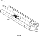
FIGS. 4 and5 are various perspective views of the track assembly ofFIG. 3 including an upper rail, a lower rail, and a latch assembly, according to an exemplary embodiment. -
FIG. 6 is a perspective view of the track assembly ofFIGS. 4 and5 including the upper rail, the latch assembly, and a carriage assembly, according to an exemplary embodiment. -
FIG. 7 is a perspective view of the track assembly ofFIGS. 4 and5 including the lower rail and the latch assembly, according to an exemplary embodiment. -
FIG. 8 is a cross-sectional view of the track assembly ofFIGS. 4 and5 , according to an exemplary embodiment. -
FIG. 9 is a perspective view of the carriage assembly ofFIG. 6 including two flanges each having a lower pocket body and an upper pocket body, according to an exemplary embodiment. -
FIG. 10 is a front view of one flange of the carriage assembly ofFIG. 9 , according to an exemplary embodiment. -
FIG. 11 is an interior perspective view of the lower pocket body of one of the flanges ofFIG. 9 , according to an exemplary embodiment. -
FIG. 12 is an exterior perspective view of the lower pocket body ofFIG. 11 , according to an exemplary embodiment. -
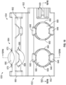
FIGS. 13 and 14 are cross-sectional views of the lower pocket body and the upper pocket body of the flange ofFIG. 10 along lines 13/14 ofFIG. 10 , according to an exemplary embodiment. -
FIGS. 15 and 16 are cross-sectional views of the lower pocket body of the flange ofFIG. 10 along lines 15/16 ofFIG. 10 , according to an exemplary embodiment. - Before turning to the figures, which illustrate certain exemplary embodiments in detail, it should be understood that the present disclosure is not limited to the details or methodology set forth in the description or illustrated in the figures. It should also be understood that the terminology used herein is for the purpose of description only and should not be regarded as limiting.
- According to an exemplary embodiment, a seat track assembly of the present disclosure includes a carriage assembly that slidably couples an upper rail and a lower rail together. Although designed to interact with one another seamlessly, manufacturing the upper rail and the lower rail can result in imperfections or variations in the profiles thereof that can cause improper interaction or looseness in between, which can permit lateral movement (i.e., up and down or side-to-side) between the upper rail and lower rail. Such imperfections or variations often require track manufacturers to manufacture, stock, and manage a variety of different carriage assemblies that each accommodate different and specific ball bearing diameters. The carriage assembly of the present disclosure not only facilitates this prevention of movement, but also includes a universal carriage that accommodates ball bearings across a wide range of bearing diameters, thereby eliminating the need to manufacture, stock, and manage many different carriage designs.
- As shown in
FIGS. 1 and2 , avehicle 10 includes an interior cabin, shown aspassenger cabin 20. In one embodiment, thevehicle 10 is configured as an on-road vehicle such as a sedan, a sport utility vehicle ("SUV"), a pickup truck, a van, and/or still another type of passenger vehicle. In other embodiments, thevehicle 10 is configured as another type of on-road vehicle such as a semi-truck, a bus, or the like. In still other embodiments, thevehicle 10 is configured as an off-road vehicle such as construction machinery, farming machinery, or the like. - As shown in
FIG. 2 , thepassenger cabin 20 includes a support surface, shown ascabin floor 30, that supports one or more seating assemblies, shown asseats 40, including one or more first seating assemblies, shown asfront seats 42, and one or more second seating assemblies, shown asrear seats 44. In some embodiments, thefront seats 42 are different than therear seats 44. In other embodiments, thefront seats 42 and therear seats 44 are the same or utilize similar components (e.g., to facilitate increased scaling for manufacturing and, therefore, a reduction in production costs). By way of example, thefront seats 42 and therear seats 44 may utilize a similar track assembly, however, the track assembly for one of thefront seats 42 or therear seats 44 may include one or more additional components (e.g., for added strength, to meet or exceed industry standards, etc.). In some embodiments, thepassenger cabin 20 does not include therear seats 44. In some embodiments, thepassenger cabin 20 only includes a singlefront seat 42. - As shown in
FIGS. 2 and3 , each of theseats 40 includes a plurality of padded components (e.g., a seat back pad or cushion, a seat bottom pad or cushion, etc.), shown as seat cushions 50, and a framing assembly, shown asframe assembly 100. As shown inFIG. 3 , theframe assembly 100 includes (i) a first frame portion, shown asseat frame assembly 110, configured to support the seat cushions 50 and (ii) a second frame portion, shown astrack assembly 200, configured to support and couple to theseat frame assembly 110 and, thereby, couple theseat 40 to thecabin floor 30. According to an exemplary embodiment, thetrack assembly 200 is adjustable (e.g., manually adjustable, electronically adjustable, etc.) such that the position of theseat 40 can be selectively adjusted (e.g., theseat 40 can be slid forward, rearward, etc.). - As shown in
FIGS. 4-7 , thetrack assembly 200 includes a first track, shown asupper rail 300, a second track, shown aslower rail 400, a securing mechanism, shown aslatch assembly 500, and a plurality of sliding couplers, shown ascarriage assemblies 600. According to an exemplary embodiment, thelatch assembly 500 is configured to selectively secure or lock theupper rail 300 in a desired position along thelower rail 400 and prevent relative movement therebetween. According to an exemplary embodiment, thecarriage assemblies 600 are configured to slidably couple theupper rail 300 to thelower rail 400 and facilitate translational or sliding movement therebetween (i.e., when thelatch assembly 500 is disengaged). - As shown in
FIGS. 6 and8 , theupper rail 300 has (i) a first end, shown asend 302, and an opposing second end, shown asend 304, that are spaced longitudinally apart and (ii) a cross-sectional profile defined by (a) a first wall, shown astop wall 306, (b) a second wall, shown asfirst sidewall 308, extending downward from a first side of thetop wall 306 and terminating with a first lip, shown asfirst flange 310, and (c) a third wall, shown assecond sidewall 312, extending downward from an opposing second side of thetop wall 306 and terminating with a second lip, shown assecond flange 314. According to the exemplary embodiment shown inFIGS. 6 and8 , thefirst sidewall 308 is longer or taller than thesecond sidewall 312 such that the cross-sectional profile is non-uniform or non-symmetrical (e.g., an "r" shaped profile, etc.). In other embodiments, the cross-sectional profile is uniform or symmetrical. - As shown in
FIGS. 7 and8 , thelower rail 400 has (i) a first end, shown asend 402, and an opposing second end, shown asend 404, that are spaced longitudinally apart and (ii) a cross-sectional profile defined by (a) a first wall, shown asbottom wall 406, (b) a second wall, shown asfirst sidewall 408, extending upward from a first side of thebottom wall 406 and terminating with a first lip, shown asfirst flange 410, and (c) a third wall, shown assecond sidewall 412, extending upward from an opposing second side of thebottom wall 406 and terminating with a second lip, shown assecond flange 414. According to the exemplary embodiment shown inFIGS. 7 and8 , thesecond sidewall 412 is longer or taller than thefirst sidewall 408 such that the cross-sectional profile is non-uniform or non-symmetrical. In other embodiments, the cross-sectional profile is uniform or symmetrical. - As shown in
FIG. 6 , thetop wall 306 of theupper rail 300 defines a plurality of apertures, shown asattachment apertures 320. According to an exemplary embodiment, theattachment apertures 320 are configured to facilitate coupling theupper rail 300, and thereby thetrack assembly 200, to theseat frame assembly 110 of theframe assembly 100 of theseat 40 using fasteners (e.g., bolts, screws, rivets, etc.). In other embodiments, theupper rail 300 is welded or otherwise coupled to theseat frame assembly 110. According to an exemplary embodiment, thebottom wall 406 of thelower rail 400 defines a plurality of apertures (e.g., similar to the attachment apertures 320). The plurality of apertures of thebottom wall 406 are configured to facilitate coupling thelower rail 400, and thereby theseat 40, to thecabin floor 30 of thevehicle 10. In other embodiments, thelower rail 400 is welded or otherwise coupled to thecabin floor 30 of thevehicle 10. - As shown in
FIG. 8 , (i) thefirst flange 410 of thelower rail 400 receives thefirst flange 310 of theupper rail 300 and (ii) thesecond flange 414 of thelower rail 400 receives thesecond flange 314 of theupper rail 300, thereby coupling thelower rail 400 and theupper rail 300 together. Afirst carriage assembly 600 is positioned between thefirst sidewall 408 of thelower rail 400 and thefirst flange 310 of theupper rail 300. Asecond carriage assembly 600 is positioned between thesecond sidewall 412 of thelower rail 400 and thesecond flange 314 of theupper rail 300. Thefirst carriage assembly 600 and thesecond carriage assembly 600 slidably couple thelower rail 400 and theupper rail 300 together. - As shown in
FIGS. 9-16 , thecarriage assembly 600 includes a bearing support, shown ascarriage 610, that supports a first plurality of bearings, shown aslower ball bearings 680, and a second plurality bearings, shown asupper ball bearings 690. As shown inFIGS. 8-12 , thecarriage 610 includes (i) an elongated body or member, shown asslide rail 620, having a first end, shown asend 622, and an opposing second end, shown asend 624, and (ii) a pair of bearing holders or flanges, shown as bearingflanges 630, with a respective one of the bearingflanges 630 positioned at each of theend 622 and theend 624 of theslide rail 620. As shown inFIGS. 8-16 , the bearingflanges 630 have a first side, shown asinner side 632, and an opposing side, shown asouter side 634. As shown inFIG. 8 , theinner side 632 of the bearingflanges 630 faces thefirst flange 310 and thesecond flange 314 of theupper rail 300, and theouter side 634 of the bearingflanges 630 faces thefirst sidewall 408 and thesecond sidewall 412 of thelower rail 400. - As shown in
FIGS. 8-16 , each of the bearingflanges 630 includes (i) a first or lower portion, shown aslower pocket body 640, coupled to theend 622 and theend 624 of theslide rail 620 and (ii) a second or upper portion, shown asupper pocket body 660, extending from thelower pocket body 640. According to the exemplary embodiment shown inFIGS. 8 ,9 ,13, and 14 , theupper pocket body 660 extends from thelower pocket body 640 at an angle such that the bearingflanges 630 have a curved or cup-like cross-sectional shape that corresponds to the shapes and profiles of thefirst sidewall 408 of thelower rail 400, thesecond sidewall 412 of thelower rail 400, thefirst flange 310 of theupper rail 300, and thesecond flange 314 of theupper rail 300. - As shown in
FIGS. 10-16 , thelower pocket body 640 of the bearingflanges 630 includes a first face, shown asinner face 642, and an opposing second face, shown asouter face 644. As shown inFIGS. 10-16 , thelower pocket body 640 defines one or more first interfaces or apertures, shown aslower pockets 646, that receive thelower ball bearings 680. According to the exemplary embodiment shown inFIGS. 10-12 ,15, and 16 , thelower pocket body 640 defines twolower pockets 646. In other embodiments, thelower pocket body 640 defines a different number of the lower pockets 646 (e.g., one, three, four, etc.). As shown inFIGS. 10 ,11 ,13, and 14 , thelower pocket body 640 includes one or more first retainers or tabs, shown as lowerinner snaps 648, protruding outward from theinner face 642 thereof and extending at least partially over each of the lower pockets 646. As shown inFIGS. 10 ,12 ,15, and 16 , thelower pocket body 640 includes one or more second retainers or tabs, shown as lowerouter snaps 650, protruding outward from theouter face 644 thereof and extending at least partially over each of the lower pockets 646. As shown inFIGS. 10-16 , the lowerinner snaps 648 and the lowerouter snaps 650 are configured (e.g., positioned, shaped, curved, etc.) to retain thelower ball bearings 680 within the lower pockets 646. - According to the exemplary embodiment shown in
FIGS. 10-12 , thelower pocket body 640 includes (i) two lowerinner snaps 648 positioned on opposing vertical sides of thelower pockets 646 and (ii) two lowerouter snaps 650 positioned on opposing horizontal sides of thelower pockets 646 such that the lowerouter snaps 650 are rotationally offset (e.g., 90 degrees) from the lowerinner snaps 648. In other embodiments, the two lowerinner snaps 648 are positioned on opposing horizontal sides of thelower pockets 646 and the two lowerouter snaps 650 are positioned on opposing vertical sides of the lower pockets 646. In still other embodiments, thelower pocket body 640 includes a different number of the lower inner snaps 648 (e.g., one, three, four, etc.) and/or the lower outer snaps 650 (e.g., one, three, four, etc.) positioned about the lower pockets 646. In such embodiments, thelower pocket body 640 may include a first number of lowerinner snaps 648 positioned about thelower pockets 646 and a second, different number of lowerouter snaps 650 positioned about the lower pockets 646. In an alternative embodiment, thelower pocket body 640 does not include one of the lowerinner snaps 648 or the lower outer snaps 650. - As shown in
FIGS. 10 ,13, and 14 , theupper pocket body 660 of the bearingflanges 630 includes a first face, shown asinner face 662, and an opposing second face, shown asouter face 664. As shown inFIGS. 10 ,13, and 14 , theupper pocket body 660 defines one or more first interfaces or apertures, shown asupper pockets 666, that receive theupper ball bearings 690. According to the exemplary embodiment shown inFIG. 10 , theupper pocket body 660 defines a singleupper pocket 666. In other embodiments, theupper pocket body 660 defines a different number of the upper pockets 666 (e.g., two, three, four, etc.). As shown inFIGS. 10 ,13, and 14 , theupper pocket body 660 includes one or more third retainers or tabs, shown as upperinner snaps 668, protruding outward from theinner face 662 thereof and extending at least partially over each of theupper pockets 666. As shown inFIG. 10 , theupper pocket body 660 includes one or more fourth retainers or tabs, shown as upperouter snaps 670, protruding outward from theouter face 664 thereof and extending at least partially over each of theupper pockets 666. As shown inFIGS. 10 ,13, and 14 , the upperinner snaps 668 and the upperouter snaps 670 are configured (e.g., positioned, shaped, curved, etc.) to retain theupper ball bearings 690 within theupper pockets 666. - According to the exemplary embodiment shown in
FIGS. 10 ,13, and 14 , theupper pocket body 660 includes (i) two upperinner snaps 668 positioned on opposing vertical sides of theupper pockets 666 and (ii) two upperouter snaps 670 positioned on opposing horizontal sides of theupper pockets 666 such that the upperouter snaps 670 are rotationally offset (e.g., 90 degrees) from the upper inner snaps 668. In other embodiments, the two upperinner snaps 668 are positioned on opposing horizontal sides of theupper pockets 666 and the two upperouter snaps 670 are positioned on opposing vertical sides of theupper pockets 666. In still other embodiments, theupper pocket body 660 includes a different number of the upper inner snaps 668 (e.g., one, three, four, etc.) and/or the upper outer snaps 670 (e.g., one, three, four, etc.). In such embodiments, theupper pocket body 660 may include a first number of upperinner snaps 668 and a second, different number of upper outer snaps 670. In an alternative embodiment, theupper pocket body 660 does not include one of the upperinner snaps 668 or the upper outer snaps 670. - As shown in
FIG. 8 , (i) one of thecarriage assemblies 600 is positioned (e.g., pressed, sandwiched, disposed, etc.) between thefirst sidewall 408 of thelower rail 400 and thefirst flange 310 of theupper rail 300 where (a) theouter side 634 of the bearingflanges 630 faces thefirst sidewall 408 of thelower rail 400 and (b) theinner side 632 of the bearingflanges 630 faces thefirst flange 310 of theupper rail 300 and (ii) one of thecarriage assemblies 600 is positioned (e.g., pressed, sandwiched, disposed, etc.) between thesecond sidewall 412 of thelower rail 400 and thesecond flange 314 of theupper rail 300 where (a) theouter side 634 of the bearingflanges 630 faces thesecond sidewall 412 of thelower rail 400 and (b) theinner side 632 of the bearingflanges 630 faces thesecond flange 314 of theupper rail 300. Thelower ball bearings 680 and theupper ball bearings 690 engage with (i) thefirst sidewall 408 of thelower rail 400 and thefirst flange 310 of theupper rail 300 and (ii) thesecond sidewall 412 of thelower rail 400 and thesecond flange 314 of theupper rail 300 to facilities sliding or translating movement of theupper rail 300 relative to thelower rail 400. - To ensure there is no looseness in the
track assembly 200, thelower ball bearings 680 and theupper ball bearings 690 must be under depression for the entire range of the profiles of theupper rails 300 and the lower rails 400. Such depression, however, cannot be too much as this will increase sliding efforts. In addition, the profiles of theupper rails 300 and thelower rails 400 may slightly vary during the manufacturing process and/or the profiles of theupper rails 300 and thelower rails 400 may slightly vary for different applications. Typically, to accommodate such variations, track manufacturers select the diameter of ball bearings based on the profile variation, which forces them to design, manufacture, and stock/manage inventory of a variety of different carriages to accommodate the range of bearing diameters. - According to an exemplary embodiment, (i) the
lower pockets 646, the lowerinner snaps 648, and the lowerouter snaps 650 and (ii) theupper pockets 666, the upperinner snaps 668, and the upperouter snaps 670 are configured (e.g., sized, shaped, flexible, etc.) to accommodate a wide range of bearing diameters, thereby facilitating the manufacturing, stocking, and managing of a single carriage design (i.e., the carriage 610). Specifically, with thecarriage 610, a track manufacturer can simply (i) identify what diameter of thelower ball bearings 680 and theupper ball bearings 690 are needed to accommodate the profiles of a respectiveupper rail 300 and a respective lower rail 400 (which diameters may be the same or different), (ii) insert thelower ball bearings 680 into thelower pockets 646 by pressing thelower ball bearings 680 against either the lowerinner snaps 648 or the lower outer snaps 650 (which are configured to flex inward under such pressure) until thelower ball bearings 680 drop into thelower pockets 646, and (iii) insert theupper ball bearings 690 into theupper pockets 666 by pressing the upper ball bearings 690 (which may be the same as or different than the lower ball bearings 680) against either the upperinner snaps 668 or the upper outer snaps 670 (which are configured to flex inward under such pressure) until theupper ball bearings 690 drop into theupper pockets 666. Once inserted, (i) the lowerinner snaps 648 and the lowerouter snaps 650 and (ii) the upperinner snaps 668 and the upperouter snaps 670 are configured to secure and hold thelower ball bearings 680 and theupper ball bearings 690, respectively, within thelower pockets 646 and theupper pockets 666, while still permitting free rotation of the largest diameter bearings and retaining the smallest diameter bearings. - As shown in
FIGS. 13-16 , (i) each of thelower pockets 646 define a first diameter, shown asmaximum pocket diameter 720, and (ii) the lowerinner snaps 648 and the lowerouter snaps 650 of each respectivelower pocket 646 define a second diameter, shown asminimum pocket diameter 730, which is defined between the free ends of the opposing lowerinner snaps 648 and the free ends of the opposing lower outer snaps 650. In some embodiments, the shape and size of the lowerinner snaps 648 and the lowerouter snaps 650 are the same such that the distance between the free ends of the opposing lowerinner snaps 648 and the distance between the free ends of the opposing lowerouter snaps 650 are the same. In other embodiments, the shape and size of the lowerinner snaps 648 and the lowerouter snaps 650 are different or varied such that the distance between the free ends of the opposing lowerinner snaps 648 and the distance between the free ends of the opposing lowerouter snaps 650 are not the same. According to an exemplary embodiment, themaximum pocket diameter 720 is about 5.4 mm (e.g., slightly greater than about 5.4 mm, 5.419 mm, 5.451 mm, between 5.4 mm and 5.5 mm, etc.) and theminimum pocket diameter 730 is about 4.0 mm (e.g., slightly less than about 4.0 mm, 3.924 mm, 3.936 mm, between 3.9 mm and 4.1 mm, etc.). - As shown in
FIG. 13 , themaximum pocket diameter 720 of thelower pockets 646 is configured to accommodate alower ball bearing 680 having a first diameter, shown asmaximum bearing diameter 700. As shown inFIG. 14 , theminimum pocket diameter 730 of thelower pockets 646 is configured to accommodate alower ball bearing 680 having a second diameter, shown asminimum bearing diameter 710. According to an exemplary embodiment, themaximum bearing diameter 700 is about 5.4 mm and theminimum bearing diameter 710 is about 4.6 mm. In other embodiments, themaximum bearing diameter 700 is larger or smaller and/orminimum bearing diameter 710 is larger or smaller based on the design of thelower pockets 646, the lowerinner snaps 648, and/or the lower outer snaps 650 (i.e., themaximum pocket diameter 720 and/or the minimum pocket diameter 730). - Further, it should be understood that the disclosure herein regarding (i) the
maximum bearing diameter 700 of thelower ball bearings 680, (ii) theminimum bearing diameter 710 of thelower ball bearings 680, (iii) themaximum pocket diameter 720 defined by thelower pockets 646, and (iv) theminimum pocket diameter 730 defined by the lowerinner snaps 648 and the lowerouter snaps 650 may similarly apply to theupper ball bearings 690, theupper pockets 666, the upperinner snaps 668, and the upper outer snaps 670. However, it should be understood that themaximum pocket diameter 720 and/or theminimum pocket diameter 730 of thelower pockets 646 and the upper pockets 666 (i) may be the same such that thelower pockets 646 and theupper pockets 666 accommodate the same range of bearing diameters or (ii) may be different such that thelower pockets 646 and theupper pockets 666 accommodate a different range of bearing diameters. - As utilized herein, the terms "approximately," "about," "substantially", and similar terms are intended to have a broad meaning in harmony with the common and accepted usage by those of ordinary skill in the art to which the subject matter of this disclosure pertains. It should be understood by those of skill in the art who review this disclosure that these terms are intended to allow a description of certain features described and claimed without restricting the scope of these features to the precise numerical ranges provided. Accordingly, these terms should be interpreted as indicating that insubstantial or inconsequential modifications or alterations of the subject matter described and claimed are considered to be within the scope of the disclosure as recited in the appended claims.
- It should be noted that the term "exemplary" and variations thereof, as used herein to describe various embodiments, are intended to indicate that such embodiments are possible examples, representations, or illustrations of possible embodiments (and such terms are not intended to connote that such embodiments are necessarily extraordinary or superlative examples).
- The term "coupled" and variations thereof, as used herein, means the joining of two members directly or indirectly to one another. Such joining may be stationary (e.g., permanent or fixed) or moveable (e.g., removable or releasable). Such joining may be achieved with the two members coupled directly to each other, with the two members coupled to each other using a separate intervening member and any additional intermediate members coupled with one another, or with the two members coupled to each other using an intervening member that is integrally formed as a single unitary body with one of the two members. If "coupled" or variations thereof are modified by an additional term (e.g., directly coupled), the generic definition of "coupled" provided above is modified by the plain language meaning of the additional term (e.g., "directly coupled" means the joining of two members without any separate intervening member), resulting in a narrower definition than the generic definition of "coupled" provided above. Such coupling may be mechanical, electrical, or fluidic.
- The term "or," as used herein, is used in its inclusive sense (and not in its exclusive sense) so that when used to connect a list of elements, the term "or" means one, some, or all of the elements in the list. Language such as the phrases "at least one of X, Y, and Z" and "at least one of X, Y, or Z," unless specifically stated otherwise, are understood to convey that an element may be either X; Y; Z; X and Y; X and Z; Y and Z; or X, Y, and Z (i.e., any combination of X, Y, and Z). Thus, such language is not generally intended to imply that certain embodiments require at least one of X, at least one of Y, and at least one of Z to each be present, unless otherwise indicated.
- References herein to the positions of elements (e.g., "top," "bottom," "above," "below") are merely used to describe the orientation of various elements in the FIGURES. It should be noted that the orientation of various elements may differ according to other exemplary embodiments, and that such variations are intended to be encompassed by the present disclosure.
- It is important to note that the construction and arrangement of the
seat 40 and components thereof (e.g., theframe assembly 100, thetrack assembly 200, etc.) as shown in the various exemplary embodiments is illustrative only. Additionally, any element disclosed in one embodiment may be incorporated or utilized with any other embodiment disclosed herein.
Claims (15)
- A carriage for a seat track assembly, the carriage comprising:an elongated body having a first end and an opposing second end; anda flange coupled to the first end of the elongated body, the flange including:a first portion having a first face and an opposing second face, the first portion defining a first aperture having a first diameter, the first portion including (i) at least two first retainers protruding outward from the first face and extending at least partially over the first aperture and (ii) at least two second retainers protruding outward from the opposing second face and extending at least partially over the first aperture, the at least two first retainers and the at least two second retainers defining a second diameter that is less than the first diameter; anda second portion extending from the first portion at an angle, the second portion having a third face and an opposing fourth face, the second portion defining a second aperture having a third diameter, the second portion including (i) at least two third retainers protruding outward from the third face and extending at least partially over the second aperture and (ii) at least two fourth retainers protruding outward from the opposing fourth face and extending at least partially over the second aperture, the at least two third retainers and the at least two fourth retainers defining a fourth diameter that is less than the third diameter;wherein at least one of (i) the first aperture, the at least two first retainers, and the at least two second retainers or (ii) the second aperture, the at least two third retainers, and the at least two fourth retainers are configured to accommodate ball bearings having diameters between about 4.6 mm and about 5.4 mm.
- The carriage of Claim 1, wherein the at least two first retainers are rotationally offset relative to the at least two second retainers.
- The carriage of Claim 1 or 2, wherein the at least two first retainers include only two first retainers and the at least two second retainers include only two second retainers.
- The carriage of Claim 3, wherein the two first retainers are positioned on opposing sides of the first aperture and the two second retainers are positioned on opposing sides of the first aperture.
- The carriage of Claim 3 or 4, wherein the two first retainers are rotationally offset 90 degrees relative to the two second retainers.
- The carriage of any one of Claims 1 to 5, wherein the first diameter is the same as the third diameter.
- The carriage of any one of Claims 1 to 5, wherein the first diameter is different than the third diameter.
- The carriage of any one of Claims 1 to 7, wherein the second diameter is the same as the fourth diameter.
- The carriage of any one of Claims 1 to 7, wherein the second diameter is different than the fourth diameter.
- The carriage of any one of Claims 1 to 9, wherein the first diameter is about 5.4 mm.
- The carriage of any one of Claims 1 to 10, wherein the second diameter is about 4.0 mm.
- The carriage of any one of Claims 1 to 11, wherein the first portion defines a third aperture adjacent the first aperture, wherein the first portion includes (i) at least two fifth retainers protruding outward from the first face and extending at least partially over the third aperture and (ii) at least two sixth retainers protruding outward from the opposing second face and extending at least partially over the third aperture.
- The carriage of Claim 12, wherein the third aperture has the first diameter, and wherein the at least two fifth retainers and the at least two sixth retainers define the second diameter.
- The carriage of any one of Claims 1 to 13, wherein the flange is a first flange, further comprising a second flange coupled to the opposing second end of the elongated body.
- The carriage of Claim 14, wherein the second flange is the same as the first flange.
Applications Claiming Priority (1)
| Application Number | Priority Date | Filing Date | Title |
|---|---|---|---|
| US202263343781P | 2022-05-19 | 2022-05-19 |
Publications (1)
| Publication Number | Publication Date |
|---|---|
| EP4279331A1 true EP4279331A1 (en) | 2023-11-22 |
Family
ID=86426050
Family Applications (1)
| Application Number | Title | Priority Date | Filing Date |
|---|---|---|---|
| EP23174036.6A Pending EP4279331A1 (en) | 2022-05-19 | 2023-05-17 | Universal ball bearing carriage for seat track assembly |
Country Status (2)
| Country | Link |
|---|---|
| US (1) | US20230375040A1 (en) |
| EP (1) | EP4279331A1 (en) |
Citations (2)
| Publication number | Priority date | Publication date | Assignee | Title |
|---|---|---|---|---|
| US6364086B1 (en) * | 1998-05-29 | 2002-04-02 | Rexroth Star Gmbh | Chain of rolling elements chain arrangement |
| US20190001842A1 (en) * | 2015-12-21 | 2019-01-03 | Adient Luxembourg Holding S.À R.L. | Bearing cage and seat rail pair for a vehicle seat |
Family Cites Families (7)
| Publication number | Priority date | Publication date | Assignee | Title |
|---|---|---|---|---|
| US2557476A (en) * | 1946-02-25 | 1951-06-19 | Schwitter Josef | Bearing |
| JP2003065350A (en) * | 2001-08-28 | 2003-03-05 | Ntn Corp | Tripod type constant velocity universal joint |
| US8251336B2 (en) * | 2008-07-09 | 2012-08-28 | Shiroki Corporation | Seat track mechanism for vehicle |
| US9738180B2 (en) * | 2016-01-27 | 2017-08-22 | Brose Fahzeugteile GmbH & Co. KG, Coburg | Adjuster track assembly for a vehicle seat |
| DE102016208364B4 (en) * | 2016-05-17 | 2021-11-18 | Lear Corporation | Seat track assembly and method of making a seat track assembly |
| US10279706B2 (en) * | 2016-09-29 | 2019-05-07 | Brose Fahrzeugteile Gmbh & Co. Kg, Coburg | Adjusting device for longitudinal adjustment of a vehicle seat and retainer for use in such an adjusting device |
| CN112224098B (en) * | 2020-10-19 | 2022-05-27 | 恺博(常熟)座椅机械部件有限公司 | Sliding rail with enhanced rigidity modulus |
-
2023
- 2023-05-16 US US18/318,467 patent/US20230375040A1/en active Pending
- 2023-05-17 EP EP23174036.6A patent/EP4279331A1/en active Pending
Patent Citations (2)
| Publication number | Priority date | Publication date | Assignee | Title |
|---|---|---|---|---|
| US6364086B1 (en) * | 1998-05-29 | 2002-04-02 | Rexroth Star Gmbh | Chain of rolling elements chain arrangement |
| US20190001842A1 (en) * | 2015-12-21 | 2019-01-03 | Adient Luxembourg Holding S.À R.L. | Bearing cage and seat rail pair for a vehicle seat |
Also Published As
| Publication number | Publication date |
|---|---|
| US20230375040A1 (en) | 2023-11-23 |
Similar Documents
| Publication | Publication Date | Title |
|---|---|---|
| US9789790B2 (en) | Tuned flexible support member and flexible suspension features for comfort carriers | |
| US12263762B2 (en) | Reinforced track assembly for vehicle seat | |
| EP1946960A1 (en) | Occupant weight measurement device for vehicle seat | |
| US20190291605A1 (en) | Longitudinal adjuster and vehicle seat | |
| WO2008061233A2 (en) | Vehicle seat back frame and method | |
| CN101448675A (en) | vehicle seat rail | |
| US9387779B2 (en) | Seat track assembly having selectable end stop positions | |
| US8146994B2 (en) | Recliner mechanism | |
| US12351083B2 (en) | Anti-chuck mechanism for seat track assembly | |
| US8899542B2 (en) | Seat track system | |
| US11214175B2 (en) | System comprising a vehicle seat track and a support | |
| US20230375040A1 (en) | Universal ball bearing carriage for seat track assembly | |
| KR20160020536A (en) | Device for adjusting the seat inclination of a motor vehicle seat | |
| EP2295289A2 (en) | Method, system and devices for fitting a bunk in a limited space | |
| EP4650218A2 (en) | Rail assembly for longitudinal adjustment of a vehicle seat | |
| CN210310056U (en) | Automobile side back cushion | |
| US20240190302A1 (en) | Seat rail | |
| US12630060B2 (en) | Locking assembly for recliner | |
| US11975638B2 (en) | Locking assembly for recliner | |
| EP4173890B1 (en) | Headrest for a backrest and backrest | |
| US20180361883A1 (en) | Seat for vehicle | |
| KR101361499B1 (en) | Seat Track for Motor Vehicle | |
| US11420536B2 (en) | Vehicle seat gearbox bracket | |
| EP2158105A1 (en) | Vehicle seat track | |
| KR20230144771A (en) | Long slide rail system for vehicle |
Legal Events
| Date | Code | Title | Description |
|---|---|---|---|
| PUAI | Public reference made under article 153(3) epc to a published international application that has entered the european phase |
Free format text: ORIGINAL CODE: 0009012 |
|
| STAA | Information on the status of an ep patent application or granted ep patent |
Free format text: STATUS: REQUEST FOR EXAMINATION WAS MADE |
|
| 17P | Request for examination filed |
Effective date: 20230517 |
|
| AK | Designated contracting states |
Kind code of ref document: A1 Designated state(s): AL AT BE BG CH CY CZ DE DK EE ES FI FR GB GR HR HU IE IS IT LI LT LU LV MC ME MK MT NL NO PL PT RO RS SE SI SK SM TR |
|
| RBV | Designated contracting states (corrected) |
Designated state(s): AL AT BE BG CH CY CZ DE DK EE ES FI FR GB GR HR HU IE IS IT LI LT LU LV MC ME MK MT NL NO PL PT RO RS SE SI SK SM TR |
|
| GRAP | Despatch of communication of intention to grant a patent |
Free format text: ORIGINAL CODE: EPIDOSNIGR1 |
|
| STAA | Information on the status of an ep patent application or granted ep patent |
Free format text: STATUS: GRANT OF PATENT IS INTENDED |
|
| RIC1 | Information provided on ipc code assigned before grant |
Ipc: B60N 2/07 20060101AFI20250708BHEP Ipc: F16C 29/04 20060101ALI20250708BHEP Ipc: F16C 33/38 20060101ALI20250708BHEP |
|
| INTG | Intention to grant announced |
Effective date: 20250808 |
|
| GRAS | Grant fee paid |
Free format text: ORIGINAL CODE: EPIDOSNIGR3 |