EP4279319A1 - Wear indicator system - Google Patents
Wear indicator system Download PDFInfo
- Publication number
- EP4279319A1 EP4279319A1 EP23168952.2A EP23168952A EP4279319A1 EP 4279319 A1 EP4279319 A1 EP 4279319A1 EP 23168952 A EP23168952 A EP 23168952A EP 4279319 A1 EP4279319 A1 EP 4279319A1
- Authority
- EP
- European Patent Office
- Prior art keywords
- assembly
- magnet
- switch
- conductor bar
- unit
- Prior art date
- Legal status (The legal status is an assumption and is not a legal conclusion. Google has not performed a legal analysis and makes no representation as to the accuracy of the status listed.)
- Pending
Links
Images


Classifications
-
- G—PHYSICS
- G08—SIGNALLING
- G08B—SIGNALLING SYSTEMS, e.g. PERSONAL CALLING SYSTEMS; ORDER TELEGRAPHS; ALARM SYSTEMS
- G08B21/00—Alarms responsive to a single specified undesired or abnormal condition and not otherwise provided for
- G08B21/18—Status alarms
-
- B—PERFORMING OPERATIONS; TRANSPORTING
- B60—VEHICLES IN GENERAL
- B60L—PROPULSION OF ELECTRICALLY-PROPELLED VEHICLES; SUPPLYING ELECTRIC POWER FOR AUXILIARY EQUIPMENT OF ELECTRICALLY-PROPELLED VEHICLES; ELECTRODYNAMIC BRAKE SYSTEMS FOR VEHICLES IN GENERAL; MAGNETIC SUSPENSION OR LEVITATION FOR VEHICLES; MONITORING OPERATING VARIABLES OF ELECTRICALLY-PROPELLED VEHICLES; ELECTRIC SAFETY DEVICES FOR ELECTRICALLY-PROPELLED VEHICLES
- B60L3/00—Electric devices on electrically-propelled vehicles for safety purposes; Monitoring operating variables, e.g. speed, deceleration or energy consumption
- B60L3/0023—Detecting, eliminating, remedying or compensating for drive train abnormalities, e.g. failures within the drive train
-
- B—PERFORMING OPERATIONS; TRANSPORTING
- B60—VEHICLES IN GENERAL
- B60L—PROPULSION OF ELECTRICALLY-PROPELLED VEHICLES; SUPPLYING ELECTRIC POWER FOR AUXILIARY EQUIPMENT OF ELECTRICALLY-PROPELLED VEHICLES; ELECTRODYNAMIC BRAKE SYSTEMS FOR VEHICLES IN GENERAL; MAGNETIC SUSPENSION OR LEVITATION FOR VEHICLES; MONITORING OPERATING VARIABLES OF ELECTRICALLY-PROPELLED VEHICLES; ELECTRIC SAFETY DEVICES FOR ELECTRICALLY-PROPELLED VEHICLES
- B60L3/00—Electric devices on electrically-propelled vehicles for safety purposes; Monitoring operating variables, e.g. speed, deceleration or energy consumption
- B60L3/12—Recording operating variables ; Monitoring of operating variables
-
- B—PERFORMING OPERATIONS; TRANSPORTING
- B60—VEHICLES IN GENERAL
- B60L—PROPULSION OF ELECTRICALLY-PROPELLED VEHICLES; SUPPLYING ELECTRIC POWER FOR AUXILIARY EQUIPMENT OF ELECTRICALLY-PROPELLED VEHICLES; ELECTRODYNAMIC BRAKE SYSTEMS FOR VEHICLES IN GENERAL; MAGNETIC SUSPENSION OR LEVITATION FOR VEHICLES; MONITORING OPERATING VARIABLES OF ELECTRICALLY-PROPELLED VEHICLES; ELECTRIC SAFETY DEVICES FOR ELECTRICALLY-PROPELLED VEHICLES
- B60L5/00—Current collectors for power supply lines of electrically-propelled vehicles
- B60L5/04—Current collectors for power supply lines of electrically-propelled vehicles using rollers or sliding shoes in contact with trolley wire
-
- B—PERFORMING OPERATIONS; TRANSPORTING
- B60—VEHICLES IN GENERAL
- B60L—PROPULSION OF ELECTRICALLY-PROPELLED VEHICLES; SUPPLYING ELECTRIC POWER FOR AUXILIARY EQUIPMENT OF ELECTRICALLY-PROPELLED VEHICLES; ELECTRODYNAMIC BRAKE SYSTEMS FOR VEHICLES IN GENERAL; MAGNETIC SUSPENSION OR LEVITATION FOR VEHICLES; MONITORING OPERATING VARIABLES OF ELECTRICALLY-PROPELLED VEHICLES; ELECTRIC SAFETY DEVICES FOR ELECTRICALLY-PROPELLED VEHICLES
- B60L5/00—Current collectors for power supply lines of electrically-propelled vehicles
- B60L5/38—Current collectors for power supply lines of electrically-propelled vehicles for collecting current from conductor rails
-
- B—PERFORMING OPERATIONS; TRANSPORTING
- B60—VEHICLES IN GENERAL
- B60L—PROPULSION OF ELECTRICALLY-PROPELLED VEHICLES; SUPPLYING ELECTRIC POWER FOR AUXILIARY EQUIPMENT OF ELECTRICALLY-PROPELLED VEHICLES; ELECTRODYNAMIC BRAKE SYSTEMS FOR VEHICLES IN GENERAL; MAGNETIC SUSPENSION OR LEVITATION FOR VEHICLES; MONITORING OPERATING VARIABLES OF ELECTRICALLY-PROPELLED VEHICLES; ELECTRIC SAFETY DEVICES FOR ELECTRICALLY-PROPELLED VEHICLES
- B60L5/00—Current collectors for power supply lines of electrically-propelled vehicles
- B60L5/40—Current collectors for power supply lines of electrically-propelled vehicles for collecting current from lines in slotted conduits
-
- B—PERFORMING OPERATIONS; TRANSPORTING
- B60—VEHICLES IN GENERAL
- B60L—PROPULSION OF ELECTRICALLY-PROPELLED VEHICLES; SUPPLYING ELECTRIC POWER FOR AUXILIARY EQUIPMENT OF ELECTRICALLY-PROPELLED VEHICLES; ELECTRODYNAMIC BRAKE SYSTEMS FOR VEHICLES IN GENERAL; MAGNETIC SUSPENSION OR LEVITATION FOR VEHICLES; MONITORING OPERATING VARIABLES OF ELECTRICALLY-PROPELLED VEHICLES; ELECTRIC SAFETY DEVICES FOR ELECTRICALLY-PROPELLED VEHICLES
- B60L9/00—Electric propulsion with power supply external to the vehicle
- B60L9/005—Interference suppression
-
- B—PERFORMING OPERATIONS; TRANSPORTING
- B66—HOISTING; LIFTING; HAULING
- B66C—CRANES; LOAD-ENGAGING ELEMENTS OR DEVICES FOR CRANES, CAPSTANS, WINCHES, OR TACKLES
- B66C15/00—Safety gear
- B66C15/06—Arrangements or use of warning devices
- B66C15/065—Arrangements or use of warning devices electrical
-
- G—PHYSICS
- G08—SIGNALLING
- G08B—SIGNALLING SYSTEMS, e.g. PERSONAL CALLING SYSTEMS; ORDER TELEGRAPHS; ALARM SYSTEMS
- G08B7/00—Signalling systems according to two or more of groups G08B3/00 - G08B6/00
- G08B7/06—Signalling systems according to two or more of groups G08B3/00 - G08B6/00 using electric transmission, e.g. involving audible and visible signalling through the use of sound and light sources
-
- H—ELECTRICITY
- H01—ELECTRIC ELEMENTS
- H01H—ELECTRIC SWITCHES; RELAYS; SELECTORS; EMERGENCY PROTECTIVE DEVICES
- H01H1/00—Contacts
- H01H1/0015—Means for testing or for inspecting contacts, e.g. wear indicator
-
- H—ELECTRICITY
- H02—GENERATION; CONVERSION OR DISTRIBUTION OF ELECTRIC POWER
- H02B—BOARDS, SUBSTATIONS OR SWITCHING ARRANGEMENTS FOR THE SUPPLY OR DISTRIBUTION OF ELECTRIC POWER
- H02B1/00—Frameworks, boards, panels, desks, casings; Details of substations or switching arrangements
- H02B1/20—Bus-bar or other wiring layouts, e.g. in cubicles, in switchyards
-
- B—PERFORMING OPERATIONS; TRANSPORTING
- B60—VEHICLES IN GENERAL
- B60L—PROPULSION OF ELECTRICALLY-PROPELLED VEHICLES; SUPPLYING ELECTRIC POWER FOR AUXILIARY EQUIPMENT OF ELECTRICALLY-PROPELLED VEHICLES; ELECTRODYNAMIC BRAKE SYSTEMS FOR VEHICLES IN GENERAL; MAGNETIC SUSPENSION OR LEVITATION FOR VEHICLES; MONITORING OPERATING VARIABLES OF ELECTRICALLY-PROPELLED VEHICLES; ELECTRIC SAFETY DEVICES FOR ELECTRICALLY-PROPELLED VEHICLES
- B60L2200/00—Type of vehicles
- B60L2200/26—Rail vehicles
-
- B—PERFORMING OPERATIONS; TRANSPORTING
- B60—VEHICLES IN GENERAL
- B60L—PROPULSION OF ELECTRICALLY-PROPELLED VEHICLES; SUPPLYING ELECTRIC POWER FOR AUXILIARY EQUIPMENT OF ELECTRICALLY-PROPELLED VEHICLES; ELECTRODYNAMIC BRAKE SYSTEMS FOR VEHICLES IN GENERAL; MAGNETIC SUSPENSION OR LEVITATION FOR VEHICLES; MONITORING OPERATING VARIABLES OF ELECTRICALLY-PROPELLED VEHICLES; ELECTRIC SAFETY DEVICES FOR ELECTRICALLY-PROPELLED VEHICLES
- B60L2200/00—Type of vehicles
- B60L2200/30—Trolleys
-
- B—PERFORMING OPERATIONS; TRANSPORTING
- B60—VEHICLES IN GENERAL
- B60L—PROPULSION OF ELECTRICALLY-PROPELLED VEHICLES; SUPPLYING ELECTRIC POWER FOR AUXILIARY EQUIPMENT OF ELECTRICALLY-PROPELLED VEHICLES; ELECTRODYNAMIC BRAKE SYSTEMS FOR VEHICLES IN GENERAL; MAGNETIC SUSPENSION OR LEVITATION FOR VEHICLES; MONITORING OPERATING VARIABLES OF ELECTRICALLY-PROPELLED VEHICLES; ELECTRIC SAFETY DEVICES FOR ELECTRICALLY-PROPELLED VEHICLES
- B60L2250/00—Driver interactions
- B60L2250/10—Driver interactions by alarm
Definitions
- Embodiments of the subject matter herein relate to electrical power transfer systems that utilize moving current collectors.
- Some items of industrial equipment include moving assemblies that run on electrical power supplied from a source offboard the moving assembly.
- One example is an overhead or gantry crane that moves along a set of tracks, where power must be supplied to the crane to operate a winch motor.
- Another example is a vehicle that receives electrical power, while moving, from an overhead line or a wayside rail.
- the moving assembly includes one or more current collector shoes, typically made of a carbon composite or carbon-metal composite material.
- the collector shoes slide along respective, stationary conductor bars (i.e., power rails or tracks), which are typically copper or steel and connected to a utility grid or other power source to provide, e.g., electrical ground and one or more positive voltage connections.
- collector shoes Due to friction between the collector shoes and metal conductor bars, the collector shoes wear out over time and must be replaced when they have reached a designated wear state (e.g., a designated remaining thickness of the collector shoe, 10-20% life left, etc., depending on the application and end-user policies).
- a designated wear state e.g., a designated remaining thickness of the collector shoe, 10-20% life left, etc., depending on the application and end-user policies.
- collector shoes may be mounted high above ground, and thus are difficult to inspect from ground level and can be overlooked by maintenance personnel, or even not included in regular maintenance assessments. Untimely collector shoe replacement may result in insufficient power delivered to the equipment, thereby degrading its performance and resulting in possible safety issues.
- a collector shoe wears down completely this may result in electrical arcing between the shoe mount and the conductor bar, and damage to the conductor bar.
- collector shoe wear indicator system may be desirable to have a collector shoe wear indicator system that differs from existing systems.
- a wear indicator system includes a switch assembly having a housing, a wear indicator circuit, and an actuator assembly.
- the housing is configured for connection to a collector shoe assembly having a collector shoe that slides in contact along a conductor bar of a conductor bar assembly for a transfer of electrical power between the collector shoe and the conductor bar.
- the wear indicator circuit is at least partially housed in the housing and includes a communication unit and a switch unit.
- the actuator assembly is operably coupled to the housing and to the switch unit.
- the actuator assembly is configured to track along the conductor bar assembly when the collector shoe assembly moves and to contact the conductor bar assembly to depress to a position to activate the switch unit when the collector shoe reaches a designated wear level.
- the wear indicator circuit is configured for the communication unit to communicate a signal indicative of the designated wear level when the switch unit is activated.
- Embodiments of the subject matter described herein relate to wear indicator systems, e.g., for alerting maintenance personnel when a collector shoe has reached a designated wear level where the collector shoe may need to be replaced.
- the collector shoe may wear down over time due to sliding in contact along a conductor bar of a conductor bar assembly, for a transfer of electrical power between the collector shoe and the conductor bar, to power a device attached to the collector shoe (such as a gantry crane or vehicle).
- the wear indicator system includes a switch assembly having a housing, a wear indicator circuit, and an actuator assembly.
- the housing is configured for connection to a collector shoe assembly having a collector shoe that slides in contact along a conductor bar of a conductor bar assembly for a transfer of electrical power between the collector shoe and the conductor bar.
- the wear indicator circuit is at least partially housed in the housing and includes a communication unit and a switch unit.
- the actuator assembly is operably coupled to the housing and to the switch unit.
- the actuator assembly is configured to track along the conductor bar assembly when the collector shoe assembly moves and to contact the conductor bar assembly to depress to a position to activate the switch unit when the collector shoe reaches a designated wear level.
- the wear indicator circuit is configured for the communication unit to communicate a signal indicative of the designated wear level when the switch unit is activated.
- the actuator assembly when it tracks along the conductor bar assembly when the collector shoe assembly moves, may move relative to the conductor bar assembly but not in contact with the conductor bar assembly, or it may move relative to the conductor bar assembly and also in contact with the conductor bar assembly.
- the actuator assembly when the collector shoe is new, the actuator assembly moves with the collector shoe assembly but not in contact with the conductor bar assembly, and when the collector shoe has worn down to a particular level (e.g., the designated wear level, or some intermediate wear level that is less than the designated wear level) the actuator assembly moves with the collector shoe assembly in contact with the conductor bar assembly.
- the actuator assembly may reduce wear on the actuator assembly and thereby prolong the period before maintenance or replacement of the actuator assembly is required.
- the actuator assembly may always contact the conductor bar assembly, regardless of collector shoe wear level.
- the designated wear level is a selected or determined level or degree of wear of a collector shoe that is indicative of or otherwise relates to a condition of the collector shoe where the collector shoe needs to be replaced, or is within a wear threshold (e.g., one to two weeks of normal use) of needing to be replaced.
- the level of wear corresponding to when the shoe should be replaced may vary from application to application. Factors include manufacturer specifications, the end use application of where the shoe is used, environmental conditions, local equipment maintenance regulations, designated safety criteria, collector shoe and conductor bar material specifications, and so on.
- the designated wear level may reflect avoiding the collector shoe completely wearing through, and it may also reflect providing a wear buffer (as mentioned above) such that even after the designated wear level is detected and a signal (e.g., maintenance alert signal) is communicated, the collector shoe will not completely wear through even with additional normal duty-cycle use for a designated time period (e.g., one week).
- a signal e.g., maintenance alert signal
- the collector shoe will not completely wear through even with additional normal duty-cycle use for a designated time period (e.g., one week).
- the communication unit includes a light element (that is, an electronic or electrical device that emits visible light or other light, such as an LED or incandescent light bulb), and the signal is embodied as changes in light emitted by the light element, e.g., from a deactivated state of the light element where no light is emitted to an activated state of the light element where light is emitted, and/or vice versa, including the possibility of repeating patterns of emitted light and lack of emitted light (e.g., a flashing light). Other possibilities include changes in light intensity, changes in emitted light coloration, etc.
- a light element that is, an electronic or electrical device that emits visible light or other light, such as an LED or incandescent light bulb
- the signal is embodied as changes in light emitted by the light element, e.g., from a deactivated state of the light element where no light is emitted to an activated state of the light element where light is emitted, and/or vice versa
- the communication unit alternatively or additionally includes a sound element (that is, an electronic or electrical device that emits sound waves, such as a speaker), and the signal is embodied as changes in sound waves emitted by the sound element, e.g., from a deactivated state of the sound element where no sound waves are emitted to an activated state of the sound element where sound waves are emitted, and/or vice versa, including the possibility of sound waves with varying intensity or varying frequency.
- a sound element that is, an electronic or electrical device that emits sound waves, such as a speaker
- the communication unit includes a wireless communication unit, e.g., having an antenna and a transceiver.
- the signal may include RF signals or other wireless signals that are configured for receipt by a second communication unit located apart from the wear indicator circuit, e.g., at a different location in a facility than where the wear indicator circuit (and related equipment) is located.
- the wireless signals include information that is configured for processing by a remote/off-board electronics device (meaning apart from the wear indicator circuit) attached to the second communication unit, for the electronics device to generate a local alert, local alarm, other local notification, or other local control signal relating to the designated wear level of the collector shoe.
- the remote electronics device may include a computer, a tablet, a cellphone/smartphone, an electronic display, etc. that is configured to convey an alert to maintenance personnel upon receiving the control signal.
- the remote electronics device may be configured, responsive to receiving the signal, to automatically: schedule a maintenance operation for maintenance personnel to replace the collector shoe (or multiple collector shoes); order replacement collector shoes (e.g., relative to a known inventory level of replacement collector shoes); track and analyze data of collector shoe usage over time; and/or the like.
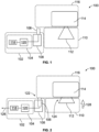
- an embodiment of a wear indicator system 100 includes a switch assembly 102 having a wear indicator circuit 104, an actuator assembly 106, and a housing 108.
- the housing is configured for connection to a collector shoe assembly 110 having a collector shoe 112 that slides in contact along a conductor bar 114 of a conductor bar assembly 116, for a transfer of electrical power between the collector shoe and the conductor bar.
- the wear indicator circuit is at least partially housed in the housing and has a communication unit 118 and a switch unit 120.
- the actuator assembly is operably coupled to the housing and to the switch unit, and is configured, as shown in FIG. 1 , to track along the conductor bar assembly when the collector shoe assembly moves, and, as shown in FIG.
- the wear indicator circuit is configured for the communication unit to communicate a signal 126 (e.g., flashing light, RF signal, or the like) indicative of the designated wear level when the switch unit is activated.
- a signal 126 e.g., flashing light, RF signal, or the like
- the switch assembly 102 since the switch assembly 102 is attached to the collector shoe assembly 110, it moves laterally along with the collector shoe assembly as the collector shoe assembly slides along and moves relative to the conductor bar 114.
- the collector shoe assembly may move, for example, under operation of one or more electric motors that are configured to drive a movement or positioning mechanism of the equipment, e.g., crane or vehicle, powered by the collector shoe-conductor bar power transfer.
- an axial distance between the actuator assembly 106 and the conductor bar assembly 116 is established by the collector shoe 112, such that when the collector shoe is new, as shown in FIG.
- the actuator assembly is located further away from the actuator assembly (and, in some embodiments, not in contact with the actuator assembly), and as the collector shoe wears down over time due to frictional interaction sliding along the conductor bar, the actuator assembly corresponding moves closer to the conductor bar assembly (see arrow 128 in FIG. 2 ). At the point when the collector shoe has worn down to the designated wear level, the actuator assembly is positioned to activate the switch unit.
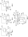
- the actuator assembly 106 may be slidingly received in an aperture 130 in the housing 108.
- the actuator assembly tracks along the conductor bar assembly (along with the collector shoe assembly) but not in contact with the conductor bar assembly.
- the actuator assembly contacts the conductor bar assembly, but does not activate the switch unit, when the collector shoe has worn down to the second wear level.
- the actuator assembly continues to contact the bar assembly and is also gradually depressed into the housing.
- FIG. 5 when the collector shoe reaches the designated wear level, the actuator assembly reaches a position in the housing to actuate the switch unit for powering the communication unit to transmit the signal.
- the actuator assembly 106 may include a plunger arm 134 and an actuator head 136.
- the plunger arm has a first end 138 disposed in the aperture 130 in the housing 108 and a distal, second end 140.
- the actuator head is attached to the second end of the plunger arm outside the housing and is configured for contact with the conductor bar assembly.
- the actuator head may be positioned and oriented so that when the switch assembly is attached to the conductor bar assembly and the collector shoe has worn down to the designated wear level, the actuator head contacts the conductor bar assembly.
- the actuator head may have a profile or shape that reduces frictional interaction between the actuator head and conductor bar assembly when the actuator head is in contact with and laterally slides along the conductor bar assembly, relative to actuator heads with other profiles or shapes.
- the actuator head includes an elongate body 142 having a first end 144 and a distal, second end 146.
- the first and second ends 144, 146 define respective sloped end surfaces (e.g., rounded or angled) 148 that are configured to present leading and trailing gaps 150, 152 between the ends of the actuator head and the conductor bar assembly when the actuator head slides in contact along the conductor bar assembly.
- the gaps established by the sloped end surfaces may facilitate the actuator assembly transitioning across gaps between adjacent sections of conductor bar (e.g., a facility may have different sections/blocks of conductor bar that are electrically isolated from one another) or transitioning over bumps or other irregularities.
- a long axis 154 of the actuator head defines a length of the actuator head.
- the length of the actuator head is from 10 cm to 20 cm long. According to one aspect, this may allow the actuator head to traverse, or more smoothly or readily traverse, gaps between adjacent sections of conductor bar, relative to an actuator head having a smaller length.
- the actuator assembly 106 may further include a first resilient member 156 (e.g., a compression spring, a rubbery polymer bushing or other polymer bushing, or the like) and a lever arm 158.
- the lever arm has a first end 160 and a second end 162 and is pivotally attached inside the housing between the first and second ends of the lever arm.
- the first end 138 of the plunger arm 134 contacts the first end of the lever arm.
- the first resilient member 156 is disposed between the housing and the first end of the lever arm and biases (pushes) the lever arm and the plunger arm upwards.
- the switch unit 120 includes a magnet switch 164, a magnet unit 166, and a second resilient member 168 (e.g., a compression spring, a rubbery polymer bushing or other polymer bushing, or the like).
- the magnet unit is slidably disposed in a slot 170 in the housing, and the second resilient member is disposed in the slot in engagement with the magnet unit.
- the magnet switch may include a normally-open magnet switch, or it may include a normally-closed magnet switch. If the magnet switch includes a normally-open magnet switch, the second resilient member may be configured to bias the magnet unit towards the magnet switch. If the magnet switch includes a normally-closed magnet switch, the second resilient member may be configured to bias the magnet unit away from the magnet switch.
- the second end of the lever arm is configured, in a first operational position when the lever arm is pivoted for the actuator assembly to be positioned fully upwards (see, e.g., FIGS. 7 and 9 ), to engage the magnet unit and retain it against the second resilient member.
- the second end of the lever arm is further configured, in a second operational position when the first end of the lever arm is pivoted downwards by the actuator assembly when the collector shoe reaches the designated wear level (see, e.g., FIGS. 8 and 10 ), to disengage from the magnet unit for the second resilient member to move the magnet unit towards the magnet switch (if the magnet switch is normally open) or to move the magnet unit away from the magnet switch (if the magnet switch is normally closed).
- a configuration with a normally-open magnet switch is shown in FIGS. 7 , 8 , 9 , and 10 .
- the second end 162 of the pivoting lever arm 158 may include a latch 172 (or other retaining member) for engaging the magnet unit and retaining it against the second resilient member when the lever arm is in its first operational position (pivoted for the actuator assembly to be positioned fully upwards).
- the latch may be a member that extends down from the second end of the lever arm and that is shaped to engage a shoulder 174 or other engagement feature of the magnet unit.
- the magnet unit may include a magnet carrier 176 (e.g., a cylindrical member configured to slide in the slot 170) and a magnet 178 disposed in and/or attached to the magnet carrier, with the magnet having a smaller diameter than the magnet carrier and protruding out from an end of the magnet carrier to thereby form the shoulder 174 between the magnet and magnet carrier.
- the magnet unit may include just the magnet (e.g., with a shoulder formed in the magnet), and/or the engagement feature could include an upper slot or other aperture formed in the magnet unit and configured to receive the end of the latch 172.
- the second end of the lever arm could include a pin that is configured to be received in a hole or other aperture formed in the magnet unit (as the engagement feature).
- FIGS. 7 , 8 , and 12 show two operational states A and B.
- the first resilient member 156 biases the actuator assembly upwards, maintaining the latch 172 in place against the shoulder 174 of the magnet unit 166.
- the magnet unit is located far enough away from the magnet switch for the magnet switch to remain open.
- the magnet unit is thereby held in place against operation of the second resilient member 168, i.e., the second resilient member pushes on the magnet unit but the latch of the lever arm prevents the magnet unit from moving.
- the magnet switch 164 being normally open, is open.
- the actuator head 136 in contact with the conductor bar assembly 116, is pushed downwards. This causes the plunger arm 134 to move downwards against the bias of the first resilient member 156. This in turn causes the lever arm to pivot, disengaging the latch 172 from the shoulder 174 of the magnet unit. The magnet unit is thereby free to move in the slot and is pushed towards the magnet switch by the second resilient member 168.
- the magnet switch is configured to close when the magnet unit is proximate, thereby closing an electrical circuit to activate the communication unit 118.
- FIG. 13 Operation of an embodiment of the wear indicator system having a normally-closed magnet switch 164 is shown in FIG. 13 (showing two operational states A and B).
- the first resilient member biases the actuator assembly upwards, maintaining the latch 172 in place against the shoulder 174 of the magnet unit 166.
- the magnet unit is located close enough to the magnet switch for the magnet switch to remain open.
- the magnet unit is thereby held in place against operation of the second resilient member 168, i.e., the second resilient member pushes on the magnet unit but the latch of the lever arm prevents the magnet unit from moving.
- the magnet switch 164 being normally closed, is open.
- the switch assembly may further include a reset member 180 slidably disposed in a reset receptacle 182 in the housing.
- the reset member is configured, when actuated, to re-engage the second end of the lever arm with the magnet unit.
- the reset member may include a reset shaft 184 and a reset actuation knob 186.
- the shaft is set in the reset receptacle. A first end of the shaft is connected to the magnet unit, and a distal, second end of the shaft is connected to the knob. In a first operational position, as shown in FIG. 7 and when the magnet unit is engaged by the lever arm, the knob is retracted into a recess in the housing.
- the reset member moves along with the magnet unit, pushing at least a portion of the knob out of the recess in the housing.
- This second operational position of the reset member is shown in FIG. 8 .
- the knob is pushed inwards back into the recess. This causes the reset shaft to push the magnet unit back to its original position, against operation of the second resilient unit. If the actuator assembly is no longer in contact with the collector bar assembly, the lever arm is free to re-engage the magnet unit to retain it in place until the lever arm is once again actuated.
- the reset member will be actuated by maintenance personnel after the wear detection system has been activated responsive to the collector shoe reaching the designated wear level, and then being replaced.
- FIG. 14 shows an exemplary embodiment of the wear indicator circuit 104.
- the wear indicator circuit may include the switch unit 120, the communication unit 118, and a power source 188, all connected (for example) in electrical series.
- the power source may include a battery or other energy storage device, or a circuit for transforming power received from the conductor bar (or bars), or a low light/low voltage solar cell, for example.
- the communication unit may include one or more light elements, in which case the communication unit may also include electrical circuity for driving the light elements (e.g., flashing, off-to-on, or the like) upon receipt of electrical power from the power source.
- the circuit is configured so that the switch unit is normally open, but when the collector shoe has worn to the designated wear level, the switch unit closes for closing (e.g., establishing a closed conductive pathway along) the electrical circuit for the power source to electrically power the communication unit.
- the communication unit includes a pre-existing light element of the industrial equipment or other equipment powered by the collector shoe/conductor bar connection.
- a pre-existing light element of the industrial equipment or other equipment powered by the collector shoe/conductor bar connection For example, a light bulb of an overhead crane, where the light bulb is normally on when the crane is operational, but the circuitry of the communication unit is configured to cause the light bulb to start flashing when the switch unit is activated.
- FIG. 15 is a side elevation view of an embodiment of the wear indicator system, showing traversal of a gap 192 in adjacent sections 114, 190 of conductor bar.
- a power distribution facility may include one conductor bar 114 that is electrically isolated and/or spaced apart from a second, adjacent conductor bar 190 (with there being the gap 192 between the two).
- the actuator head 136 may be dimensioned to be long enough to span the gap 192. Additionally, the sloped end surfaces of the actuator head may facilitate traversal across the gap.
- a wear indicator system indicates when a power collector shoe has reached its designated wear level and needs to be replaced, giving the operators and maintenance staff advance notice (e.g., up to 7 days).
- the system is configured to initiate blinking of a high brightness LED when the shoe has reached a specific wear limit.
- a mechanical switch is installed to the side of each shoe on the power collection assembly. As the collector wears down (i.e., its height decreases), the mechanical switch slowly lowers vertically. Once the shoe has reached its designated height or wear level, the switch is activated mechanically and connects a battery to an LED activating circuit. This circuit then causes the LED to blink continuously until the shoe is changed or until the battery runs out (a fresh battery should run continuously for 3-7 days).
- the LED activating circuit can have one of the three possible locations: installed inside the mechanical switch assembly (30-80 ft above ground on the side of the power collection shoe) and include the LED with battery thus the system will have a direct and short switch-circuit-LED wiring; installed inside the crane's side panel box and include the LED with battery (or tap into power available inside the box) and include a direct but long switch-circuit-LED wiring (e.g., long wire between the switch 30-80 ft above ground and the activating circuit); or the activating circuit can be separated between the two locations and work wirelessly.
- the transmitter part of the circuit along with transmitter battery is installed in the mechanical switch assembly (e.g., 30-80 ft above ground on the side of the power collection shoe) and the receiver end of the circuit is installed inside the crane or other equipment's side panel box or inside a handheld device along with the LED and battery (if it is not possible to use power already available in the box or handheld device).
- the mechanical switch assembly e.g., 30-80 ft above ground on the side of the power collection shoe
- the receiver end of the circuit is installed inside the crane or other equipment's side panel box or inside a handheld device along with the LED and battery (if it is not possible to use power already available in the box or handheld device).
- methods of installation may include changes to a collector shoe mounting bracket, e.g., the addition of the mounting holes for indicator mechanical switch assembly; and/or modifications to the crane or other equipment's side panel box wiring and addition of a running wire along the collector arm.
Landscapes
- Engineering & Computer Science (AREA)
- Mechanical Engineering (AREA)
- Power Engineering (AREA)
- Transportation (AREA)
- Physics & Mathematics (AREA)
- General Physics & Mathematics (AREA)
- Life Sciences & Earth Sciences (AREA)
- Sustainable Development (AREA)
- Sustainable Energy (AREA)
- Business, Economics & Management (AREA)
- Emergency Management (AREA)
- Train Traffic Observation, Control, And Security (AREA)
- A Measuring Device Byusing Mechanical Method (AREA)
- Current-Collector Devices For Electrically Propelled Vehicles (AREA)
Abstract
A wear indicator system (100) may include a switch assembly (102) having a housing (108), a wear indicator circuit (104), and an actuator assembly (106). The housing (108) may connect to a collector shoe assembly (110) having a collector shoe (112) that slides in contact along a conductor bar (114) of a conductor bar assembly (116), for transferring electrical power between the collector shoe (112) and the conductor bar (114). The wear indicator circuit (104) may include a communication unit (118) and a switch unit (120). The actuator assembly (106) may be operably coupled to the housing (108) and to the switch unit (120) and may track along the conductor bar assembly (116) when the collector shoe assembly (110) moves and may contact the conductor bar assembly (116) to depress to a position to activate the switch unit (120) responsive to the collector shoe (112) reaching a designated wear level. The communication unit (118) may communicate a signal indicative of the designated wear level responsive to the switch unit (120) being activated.
Description
- This application claims priority to
U.S. Provisional Application No. 63/342,380 (filed 16-May-2022 - Embodiments of the subject matter herein relate to electrical power transfer systems that utilize moving current collectors.
- Some items of industrial equipment include moving assemblies that run on electrical power supplied from a source offboard the moving assembly. One example is an overhead or gantry crane that moves along a set of tracks, where power must be supplied to the crane to operate a winch motor. Another example is a vehicle that receives electrical power, while moving, from an overhead line or a wayside rail. To transfer power to the moving assembly, the moving assembly includes one or more current collector shoes, typically made of a carbon composite or carbon-metal composite material. The collector shoes slide along respective, stationary conductor bars (i.e., power rails or tracks), which are typically copper or steel and connected to a utility grid or other power source to provide, e.g., electrical ground and one or more positive voltage connections.
- Due to friction between the collector shoes and metal conductor bars, the collector shoes wear out over time and must be replaced when they have reached a designated wear state (e.g., a designated remaining thickness of the collector shoe, 10-20% life left, etc., depending on the application and end-user policies). For overhead applications, collector shoes may be mounted high above ground, and thus are difficult to inspect from ground level and can be overlooked by maintenance personnel, or even not included in regular maintenance assessments. Untimely collector shoe replacement may result in insufficient power delivered to the equipment, thereby degrading its performance and resulting in possible safety issues. In addition, if a collector shoe wears down completely, this may result in electrical arcing between the shoe mount and the conductor bar, and damage to the conductor bar.
- To avoid untimely collector shoe replacement, past systems have been outfitted with means for remotely monitoring collector shoe wear. Examples include optical sensors (e.g., cameras), and electrical alarm circuits embedded in the shoe body itself that are activated when the collector shoe reaches a designated wear level. However, the former is expensive to implement and difficult to calibrate (in terms of correctly visually assessing the relative wear level of the collector shoe through a camera feed), and the latter require extensive modifications to the collector shoe itself, which increases cost and may affect reliability and performance.
- It may be desirable to have a collector shoe wear indicator system that differs from existing systems.
- In an embodiment, a wear indicator system includes a switch assembly having a housing, a wear indicator circuit, and an actuator assembly. The housing is configured for connection to a collector shoe assembly having a collector shoe that slides in contact along a conductor bar of a conductor bar assembly for a transfer of electrical power between the collector shoe and the conductor bar. The wear indicator circuit is at least partially housed in the housing and includes a communication unit and a switch unit. The actuator assembly is operably coupled to the housing and to the switch unit. The actuator assembly is configured to track along the conductor bar assembly when the collector shoe assembly moves and to contact the conductor bar assembly to depress to a position to activate the switch unit when the collector shoe reaches a designated wear level. The wear indicator circuit is configured for the communication unit to communicate a signal indicative of the designated wear level when the switch unit is activated.
- The inventive subject matter may be understood from reading the following description of non-limiting embodiments, with reference to the attached drawings, wherein below:
-
FIG. 1 is a schematic view of a first embodiment of a wear indicator system in a first operational state; -
FIG. 2 is a schematic view of the first embodiment of the wear indicator system in a second operational state; -
FIGS. 3, 4, and 5 are schematic views of a second embodiment of a wear indicator system in first, second, and third operational states, respectively; -
FIG. 6 is a schematic view of an embodiment of an actuator assembly; -
FIGS. 7 and8 are side elevation views, partially in cut-away to show internal parts, of a third embodiment of a wear indicator system in first and second operational states, respectively; -
FIGS. 9 and10 are end views of another embodiment of a wear indicator system in first and second operational states, respectively; -
FIG. 11 is a schematic view of an embodiment of a magnet unit in combination with a lever arm; -
FIG. 12 , having parts (A) and (B), is a schematic view of another embodiment of a wear indicator system in first and second operational states, respectively; -
FIG. 13 , having parts (A) and (B), is a schematic view of another embodiment of a wear indicator system in first and second operational states, respectively; -
FIG. 14 is a simplified electrical circuit diagram showing an embodiment of a wear indicator circuit; and -
FIG. 15 is a side elevation view, partially in cut-away to show internal parts, of another embodiment of a wear indicator system, showing traversal of a gap in adjacent sections of conductor bar. - Embodiments of the subject matter described herein relate to wear indicator systems, e.g., for alerting maintenance personnel when a collector shoe has reached a designated wear level where the collector shoe may need to be replaced. For example, the collector shoe may wear down over time due to sliding in contact along a conductor bar of a conductor bar assembly, for a transfer of electrical power between the collector shoe and the conductor bar, to power a device attached to the collector shoe (such as a gantry crane or vehicle).
- In one embodiment, the wear indicator system includes a switch assembly having a housing, a wear indicator circuit, and an actuator assembly. The housing is configured for connection to a collector shoe assembly having a collector shoe that slides in contact along a conductor bar of a conductor bar assembly for a transfer of electrical power between the collector shoe and the conductor bar. The wear indicator circuit is at least partially housed in the housing and includes a communication unit and a switch unit. The actuator assembly is operably coupled to the housing and to the switch unit. The actuator assembly is configured to track along the conductor bar assembly when the collector shoe assembly moves and to contact the conductor bar assembly to depress to a position to activate the switch unit when the collector shoe reaches a designated wear level. The wear indicator circuit is configured for the communication unit to communicate a signal indicative of the designated wear level when the switch unit is activated.
- According to various aspects, the actuator assembly, when it tracks along the conductor bar assembly when the collector shoe assembly moves, may move relative to the conductor bar assembly but not in contact with the conductor bar assembly, or it may move relative to the conductor bar assembly and also in contact with the conductor bar assembly. In embodiments, when the collector shoe is new, the actuator assembly moves with the collector shoe assembly but not in contact with the conductor bar assembly, and when the collector shoe has worn down to a particular level (e.g., the designated wear level, or some intermediate wear level that is less than the designated wear level) the actuator assembly moves with the collector shoe assembly in contact with the conductor bar assembly. (Minimizing or otherwise reducing an amount of time in which the actuator assembly contacts the conductor bar assembly may reduce wear on the actuator assembly and thereby prolong the period before maintenance or replacement of the actuator assembly is required.) In other embodiments, the actuator assembly may always contact the conductor bar assembly, regardless of collector shoe wear level.
- According to one aspect, the designated wear level is a selected or determined level or degree of wear of a collector shoe that is indicative of or otherwise relates to a condition of the collector shoe where the collector shoe needs to be replaced, or is within a wear threshold (e.g., one to two weeks of normal use) of needing to be replaced. The level of wear corresponding to when the shoe should be replaced may vary from application to application. Factors include manufacturer specifications, the end use application of where the shoe is used, environmental conditions, local equipment maintenance regulations, designated safety criteria, collector shoe and conductor bar material specifications, and so on. In embodiments, the designated wear level may reflect avoiding the collector shoe completely wearing through, and it may also reflect providing a wear buffer (as mentioned above) such that even after the designated wear level is detected and a signal (e.g., maintenance alert signal) is communicated, the collector shoe will not completely wear through even with additional normal duty-cycle use for a designated time period (e.g., one week). This recognizes that it may not be possible to immediately replace a collector shoe (e.g., due to required continued use of the equipment in question, or due to unavailability of maintenance personnel or equipment), and that maintenance personnel may not be immediately cognizant of the communicated signal.
- In embodiments, the communication unit includes a light element (that is, an electronic or electrical device that emits visible light or other light, such as an LED or incandescent light bulb), and the signal is embodied as changes in light emitted by the light element, e.g., from a deactivated state of the light element where no light is emitted to an activated state of the light element where light is emitted, and/or vice versa, including the possibility of repeating patterns of emitted light and lack of emitted light (e.g., a flashing light). Other possibilities include changes in light intensity, changes in emitted light coloration, etc. In other embodiments, the communication unit alternatively or additionally includes a sound element (that is, an electronic or electrical device that emits sound waves, such as a speaker), and the signal is embodied as changes in sound waves emitted by the sound element, e.g., from a deactivated state of the sound element where no sound waves are emitted to an activated state of the sound element where sound waves are emitted, and/or vice versa, including the possibility of sound waves with varying intensity or varying frequency.
- In other embodiments, the communication unit includes a wireless communication unit, e.g., having an antenna and a transceiver. Here, the signal may include RF signals or other wireless signals that are configured for receipt by a second communication unit located apart from the wear indicator circuit, e.g., at a different location in a facility than where the wear indicator circuit (and related equipment) is located. The wireless signals include information that is configured for processing by a remote/off-board electronics device (meaning apart from the wear indicator circuit) attached to the second communication unit, for the electronics device to generate a local alert, local alarm, other local notification, or other local control signal relating to the designated wear level of the collector shoe. For example, the remote electronics device may include a computer, a tablet, a cellphone/smartphone, an electronic display, etc. that is configured to convey an alert to maintenance personnel upon receiving the control signal. According on one aspect, the remote electronics device may be configured, responsive to receiving the signal, to automatically: schedule a maintenance operation for maintenance personnel to replace the collector shoe (or multiple collector shoes); order replacement collector shoes (e.g., relative to a known inventory level of replacement collector shoes); track and analyze data of collector shoe usage over time; and/or the like.
- Now with reference to the
FIGS. 1 and 2 , an embodiment of awear indicator system 100 includes aswitch assembly 102 having awear indicator circuit 104, anactuator assembly 106, and ahousing 108. The housing is configured for connection to acollector shoe assembly 110 having acollector shoe 112 that slides in contact along aconductor bar 114 of aconductor bar assembly 116, for a transfer of electrical power between the collector shoe and the conductor bar. The wear indicator circuit is at least partially housed in the housing and has acommunication unit 118 and aswitch unit 120. The actuator assembly is operably coupled to the housing and to the switch unit, and is configured, as shown inFIG. 1 , to track along the conductor bar assembly when the collector shoe assembly moves, and, as shown inFIG. 2 , to contact the conductor bar assembly to depress to aposition 122 to activate the switch unit when the collector shoe reaches a designatedwear level 124. The wear indicator circuit is configured for the communication unit to communicate a signal 126 (e.g., flashing light, RF signal, or the like) indicative of the designated wear level when the switch unit is activated. - According to an aspect, since the
switch assembly 102 is attached to thecollector shoe assembly 110, it moves laterally along with the collector shoe assembly as the collector shoe assembly slides along and moves relative to theconductor bar 114. (The collector shoe assembly may move, for example, under operation of one or more electric motors that are configured to drive a movement or positioning mechanism of the equipment, e.g., crane or vehicle, powered by the collector shoe-conductor bar power transfer.) Also, an axial distance between theactuator assembly 106 and theconductor bar assembly 116 is established by thecollector shoe 112, such that when the collector shoe is new, as shown inFIG. 1 , the actuator assembly is located further away from the actuator assembly (and, in some embodiments, not in contact with the actuator assembly), and as the collector shoe wears down over time due to frictional interaction sliding along the conductor bar, the actuator assembly corresponding moves closer to the conductor bar assembly (see arrow 128 inFIG. 2 ). At the point when the collector shoe has worn down to the designated wear level, the actuator assembly is positioned to activate the switch unit. - In embodiments, with reference to
FIGS. 3, 4, and 5 , theactuator assembly 106 may be slidingly received in anaperture 130 in thehousing 108. Initially, as shown inFIG. 3 , when thecollector shoe 112 is new, or has worn down to a level less than asecond wear level 132 that is less than the designatedwear level 124, the actuator assembly tracks along the conductor bar assembly (along with the collector shoe assembly) but not in contact with the conductor bar assembly. As shown inFIG. 4 , the actuator assembly contacts the conductor bar assembly, but does not activate the switch unit, when the collector shoe has worn down to the second wear level. As the collector shoe continues to wear down between the second wear level and the designated wear level, the actuator assembly continues to contact the bar assembly and is also gradually depressed into the housing. As shown inFIG. 5 , when the collector shoe reaches the designated wear level, the actuator assembly reaches a position in the housing to actuate the switch unit for powering the communication unit to transmit the signal. - In embodiments, with reference to
FIG. 6 , theactuator assembly 106 may include aplunger arm 134 and anactuator head 136. The plunger arm has afirst end 138 disposed in theaperture 130 in thehousing 108 and a distal,second end 140. The actuator head is attached to the second end of the plunger arm outside the housing and is configured for contact with the conductor bar assembly. (For example, the actuator head may be positioned and oriented so that when the switch assembly is attached to the conductor bar assembly and the collector shoe has worn down to the designated wear level, the actuator head contacts the conductor bar assembly. Also, the actuator head may have a profile or shape that reduces frictional interaction between the actuator head and conductor bar assembly when the actuator head is in contact with and laterally slides along the conductor bar assembly, relative to actuator heads with other profiles or shapes.) The actuator head includes anelongate body 142 having afirst end 144 and a distal,second end 146. The first and second ends 144, 146 define respective sloped end surfaces (e.g., rounded or angled) 148 that are configured to present leading and trailinggaps - A
long axis 154 of the actuator head defines a length of the actuator head. In embodiments, the length of the actuator head is from 10 cm to 20 cm long. According to one aspect, this may allow the actuator head to traverse, or more smoothly or readily traverse, gaps between adjacent sections of conductor bar, relative to an actuator head having a smaller length. - In embodiments, with reference to
FIGS. 7 ,8 ,9 , and10 , theactuator assembly 106 may further include a first resilient member 156 (e.g., a compression spring, a rubbery polymer bushing or other polymer bushing, or the like) and alever arm 158. The lever arm has afirst end 160 and asecond end 162 and is pivotally attached inside the housing between the first and second ends of the lever arm. Thefirst end 138 of theplunger arm 134 contacts the first end of the lever arm. The firstresilient member 156 is disposed between the housing and the first end of the lever arm and biases (pushes) the lever arm and the plunger arm upwards. Theswitch unit 120 includes amagnet switch 164, amagnet unit 166, and a second resilient member 168 (e.g., a compression spring, a rubbery polymer bushing or other polymer bushing, or the like). The magnet unit is slidably disposed in aslot 170 in the housing, and the second resilient member is disposed in the slot in engagement with the magnet unit. The magnet switch may include a normally-open magnet switch, or it may include a normally-closed magnet switch. If the magnet switch includes a normally-open magnet switch, the second resilient member may be configured to bias the magnet unit towards the magnet switch. If the magnet switch includes a normally-closed magnet switch, the second resilient member may be configured to bias the magnet unit away from the magnet switch. - The second end of the lever arm is configured, in a first operational position when the lever arm is pivoted for the actuator assembly to be positioned fully upwards (see, e.g.,
FIGS. 7 and9 ), to engage the magnet unit and retain it against the second resilient member. The second end of the lever arm is further configured, in a second operational position when the first end of the lever arm is pivoted downwards by the actuator assembly when the collector shoe reaches the designated wear level (see, e.g.,FIGS. 8 and10 ), to disengage from the magnet unit for the second resilient member to move the magnet unit towards the magnet switch (if the magnet switch is normally open) or to move the magnet unit away from the magnet switch (if the magnet switch is normally closed). A configuration with a normally-open magnet switch is shown inFIGS. 7 ,8 ,9 , and10 . - As shown in
FIGS. 7 ,8 , and11 , in embodiments, thesecond end 162 of the pivotinglever arm 158 may include a latch 172 (or other retaining member) for engaging the magnet unit and retaining it against the second resilient member when the lever arm is in its first operational position (pivoted for the actuator assembly to be positioned fully upwards). The latch may be a member that extends down from the second end of the lever arm and that is shaped to engage ashoulder 174 or other engagement feature of the magnet unit. ("Engagement feature" means a structure of the magnet unit shaped to engage a latch or other retaining member attached to the second end of the lever arm.) For example, the magnet unit may include a magnet carrier 176 (e.g., a cylindrical member configured to slide in the slot 170) and amagnet 178 disposed in and/or attached to the magnet carrier, with the magnet having a smaller diameter than the magnet carrier and protruding out from an end of the magnet carrier to thereby form theshoulder 174 between the magnet and magnet carrier. Alternatively, the magnet unit may include just the magnet (e.g., with a shoulder formed in the magnet), and/or the engagement feature could include an upper slot or other aperture formed in the magnet unit and configured to receive the end of thelatch 172. In other embodiments, the second end of the lever arm could include a pin that is configured to be received in a hole or other aperture formed in the magnet unit (as the engagement feature). - Operation of an embodiment of the wear indicator system having a normally-
open magnet switch 164 is shown inFIGS. 7 ,8 , and12 (showing two operational states A and B). InFIGS. 7 and12(A) , before the collector shoe has worn down to the designated wear level, the firstresilient member 156 biases the actuator assembly upwards, maintaining thelatch 172 in place against theshoulder 174 of themagnet unit 166. Here, the magnet unit is located far enough away from the magnet switch for the magnet switch to remain open. The magnet unit is thereby held in place against operation of the secondresilient member 168, i.e., the second resilient member pushes on the magnet unit but the latch of the lever arm prevents the magnet unit from moving. Themagnet switch 164, being normally open, is open. With reference toFIGS. 8 and12(B) , when the collector shoe wears down to the designated wear level, theactuator head 136, in contact with theconductor bar assembly 116, is pushed downwards. This causes theplunger arm 134 to move downwards against the bias of the firstresilient member 156. This in turn causes the lever arm to pivot, disengaging thelatch 172 from theshoulder 174 of the magnet unit. The magnet unit is thereby free to move in the slot and is pushed towards the magnet switch by the secondresilient member 168. The magnet switch is configured to close when the magnet unit is proximate, thereby closing an electrical circuit to activate thecommunication unit 118. - Operation of an embodiment of the wear indicator system having a normally-closed
magnet switch 164 is shown inFIG. 13 (showing two operational states A and B). InFIG. 13(A) , before the collector shoe has worn down to the designated wear level, the first resilient member biases the actuator assembly upwards, maintaining thelatch 172 in place against theshoulder 174 of themagnet unit 166. Here, the magnet unit is located close enough to the magnet switch for the magnet switch to remain open. The magnet unit is thereby held in place against operation of the secondresilient member 168, i.e., the second resilient member pushes on the magnet unit but the latch of the lever arm prevents the magnet unit from moving. Themagnet switch 164, being normally closed, is open. With reference toFIG. 13(B) , when the collector shoe wears down to the designated wear level, theactuator head 136, in contact with theconductor bar assembly 116, is pushed downwards. This causes theplunger arm 134 to move downwards against the bias of the firstresilient member 156. This in turn causes the lever arm to pivot, disengaging thelatch 172 from theshoulder 174 of the magnet unit. The magnet unit is thereby free to move in the slot and is pushed away from the magnet switch by the secondresilient member 168. The magnet switch is configured to close when the magnet unit is moved away, thereby closing an electrical circuit to activate thecommunication unit 118. - In embodiments, the switch assembly may further include a
reset member 180 slidably disposed in areset receptacle 182 in the housing. The reset member is configured, when actuated, to re-engage the second end of the lever arm with the magnet unit. For example, with reference toFIGS. 7 and8 , the reset member may include areset shaft 184 and areset actuation knob 186. The shaft is set in the reset receptacle. A first end of the shaft is connected to the magnet unit, and a distal, second end of the shaft is connected to the knob. In a first operational position, as shown inFIG. 7 and when the magnet unit is engaged by the lever arm, the knob is retracted into a recess in the housing. When the lever arm is actuated to release the magnet unit, the reset member moves along with the magnet unit, pushing at least a portion of the knob out of the recess in the housing. This second operational position of the reset member is shown inFIG. 8 . To reset the magnet unit, the knob is pushed inwards back into the recess. This causes the reset shaft to push the magnet unit back to its original position, against operation of the second resilient unit. If the actuator assembly is no longer in contact with the collector bar assembly, the lever arm is free to re-engage the magnet unit to retain it in place until the lever arm is once again actuated. Typically, the reset member will be actuated by maintenance personnel after the wear detection system has been activated responsive to the collector shoe reaching the designated wear level, and then being replaced. -
FIG. 14 shows an exemplary embodiment of thewear indicator circuit 104. The wear indicator circuit may include theswitch unit 120, thecommunication unit 118, and apower source 188, all connected (for example) in electrical series. The power source may include a battery or other energy storage device, or a circuit for transforming power received from the conductor bar (or bars), or a low light/low voltage solar cell, for example. The communication unit, as noted above, may include one or more light elements, in which case the communication unit may also include electrical circuity for driving the light elements (e.g., flashing, off-to-on, or the like) upon receipt of electrical power from the power source. The circuit is configured so that the switch unit is normally open, but when the collector shoe has worn to the designated wear level, the switch unit closes for closing (e.g., establishing a closed conductive pathway along) the electrical circuit for the power source to electrically power the communication unit. - In embodiments, the communication unit includes a pre-existing light element of the industrial equipment or other equipment powered by the collector shoe/conductor bar connection. For example, a light bulb of an overhead crane, where the light bulb is normally on when the crane is operational, but the circuitry of the communication unit is configured to cause the light bulb to start flashing when the switch unit is activated.
-
FIG. 15 is a side elevation view of an embodiment of the wear indicator system, showing traversal of agap 192 inadjacent sections conductor bar 114 that is electrically isolated and/or spaced apart from a second, adjacent conductor bar 190 (with there being thegap 192 between the two). Theactuator head 136 may be dimensioned to be long enough to span thegap 192. Additionally, the sloped end surfaces of the actuator head may facilitate traversal across the gap. - In embodiments, a wear indicator system indicates when a power collector shoe has reached its designated wear level and needs to be replaced, giving the operators and maintenance staff advance notice (e.g., up to 7 days). In embodiments, the system is configured to initiate blinking of a high brightness LED when the shoe has reached a specific wear limit.
- In embodiments, a mechanical switch is installed to the side of each shoe on the power collection assembly. As the collector wears down (i.e., its height decreases), the mechanical switch slowly lowers vertically. Once the shoe has reached its designated height or wear level, the switch is activated mechanically and connects a battery to an LED activating circuit. This circuit then causes the LED to blink continuously until the shoe is changed or until the battery runs out (a fresh battery should run continuously for 3-7 days). The LED activating circuit can have one of the three possible locations: installed inside the mechanical switch assembly (30-80 ft above ground on the side of the power collection shoe) and include the LED with battery thus the system will have a direct and short switch-circuit-LED wiring; installed inside the crane's side panel box and include the LED with battery (or tap into power available inside the box) and include a direct but long switch-circuit-LED wiring (e.g., long wire between the switch 30-80 ft above ground and the activating circuit); or the activating circuit can be separated between the two locations and work wirelessly. The transmitter part of the circuit along with transmitter battery is installed in the mechanical switch assembly (e.g., 30-80 ft above ground on the side of the power collection shoe) and the receiver end of the circuit is installed inside the crane or other equipment's side panel box or inside a handheld device along with the LED and battery (if it is not possible to use power already available in the box or handheld device).
- In embodiments, methods of installation may include changes to a collector shoe mounting bracket, e.g., the addition of the mounting holes for indicator mechanical switch assembly; and/or modifications to the crane or other equipment's side panel box wiring and addition of a running wire along the collector arm.
- The singular forms "a", "an", and "the" include plural references unless the context clearly dictates otherwise. "Optional" or "optionally" means that the subsequently described event or circumstance may or may not occur, and that the description may include instances where the event occurs and instances where it does not. Approximating language, as used herein throughout the specification, may be applied to modify any quantitative representation that could permissibly vary without resulting in a change in the basic function to which it may be related. Accordingly, a value modified by a term or terms, such as "about," "substantially," and "approximately," may be not to be limited to the precise value specified. In at least some instances, the approximating language may correspond to the precision of an instrument for measuring the value. Here and throughout the specification, range limitations may be combined and/or interchanged, such ranges may be identified and include all the sub-ranges contained therein unless context or language indicates otherwise.
- This written description uses examples to disclose the embodiments, including the best mode, and to enable a person of ordinary skill in the art to practice the embodiments, including making and using any devices or systems and performing any incorporated methods.
Claims (15)
- A wear indicator system (100), comprising:a switch assembly (102) comprising a housing (108) configured for connection to a collector shoe assembly (110) having a collector shoe (112) that slides in contact along a conductor bar (114) of a conductor bar assembly (116) for a transfer of electrical power between the collector shoe (112) and the conductor bar (114),the switch assembly (102) including a wear indicator circuit (104) at least partially housed in the housing (108) and having a communication unit (118) and a switch unit (120), the switch assembly (102) including an actuator assembly (106) operably coupled to the housing (108) and to the switch unit (120),the actuator assembly (106) configured to track along the conductor bar assembly (116) while the collector shoe assembly (110) moves and to contact the conductor bar assembly (116) to depress to a position to activate the switch unit (120) responsive to the collector shoe (112) reaching a designated wear level,the wear indicator circuit (104) is configured for the communication unit (118) to communicate a signal indicative of the designated wear level responsive to activation of the switch unit (120).
- The system (100) of claim 1, wherein the communication unit (118) comprises a wireless transmitter configured to be activated responsive to the activation of the switch unit (120), and the signal comprises a radio frequency (RF) signal generated by the wireless transmitter and configured for receipt by an off-board electronic device.
- The system (100) of claim 1, wherein the actuator assembly (106) is configured to:track along the conductor bar assembly (116) while the collector shoe assembly (110) moves but not contact the conductor bar assembly (116) while the collector shoe (112) has a wear level less than a second wear level that is less than the designated wear level; andcontact the conductor bar assembly (116), but not activate the switch unit (120), while the wear level is more than the second wear level and less than the designated wear level.
- The system (100) of claim 1, wherein the actuator assembly (106) comprises a plunger arm (134) and an actuator head (136), the plunger arm (134) having a first end (138) disposed in an aperture (130) in the housing (108) and a second end (140), the actuator head (136) attached to the second end (140) of the plunger arm (134) outside the housing (108) and configured for contact with the conductor bar assembly (116),the actuator head (136) including an elongate body (142) having a first end (144) and a distal, second end (146),the first and second end (144, 146) of the actuator head body (142) defining respective sloped end surfaces that are configured to present leading and trailing gaps between the actuator head (136) and the conductor bar assembly (116) while the actuator head (136) moves in contact along the conductor bar assembly (116).
- The system (100) of claim 4, wherein a length of the actuator head (136) is between ten and twenty centimeters.
- The system (100) of claim 1, wherein the actuator assembly (106) comprises a plunger arm (134) and an actuator head (136), the plunger arm (134) having a first end (138) disposed in an aperture (130) in the housing (108) and a second end (140), the actuator head (136) attached to the second end (140) of the plunger arm (134) outside the housing (108) and configured for contact with the conductor bar assembly (116),the actuator assembly (106) further comprising a first resilient member (156) and a lever arm (158), the lever arm (158) having a first end (160) and a second end (162) and pivotally attached inside the housing (108) between the first and second ends (160, 162) of the lever arm (158), the first end (138) of the plunger arm (134) contacting the first end (160) of the lever arm (158), and the first resilient member (156) disposed between the housing (108) and the first end (138) of the lever arm (158) and biasing the lever arm (158) and the plunger arm (134) upwards,the switch unit (120) comprising a magnet switch (164), a magnet unit (166), and a second resilient member (168), the magnet unit (166) slidably disposed in a slot (170) in the housing (108), and the second resilient member (168) disposed in the slot (170) in engagement with the magnet unit (166) and one of biasing the magnet unit (166) towards or away from the magnet switch (164),the second end (140) of the lever arm (158) is configured, in a first operational position while the lever arm (158) is pivoted for the actuator assembly (106) to be positioned fully upwards, to engage the magnet unit (166) and retain the magnet unit (166) against the second resilient member (168),the second end (140) of the lever arm (158) is further configured, in a second operational position while the first end (138) of the lever arm (158) is pivoted downward by the actuator assembly (106) responsive to the collector shoe (112) reaching the designated wear level, to disengage from the magnet unit (166) for the second resilient member (168) to one of move the magnet unit (166) toward or away from the magnet switch (164).
- The system (100) of claim 6, wherein the magnet unit (166) comprises a magnet carrier (176) and a magnet (178) attached to the magnet carrier (176), wherein one or more of the magnet carrier (176), the magnet (178), or the magnet (178) in conjunction with the magnet carrier (176) define an engagement feature, and the second end (162) of the lever arm (158) defines a latch shoulder that is configured to selectively engage with the engagement feature of the magnet unit (166).
- The system (100) of claim 6, wherein the switch assembly (102) further comprises a reset member (180) slidably disposed in a reset receptacle (182) in the housing (108), the reset member (180) configured to re-engage the second end (162) of the lever arm (158) with the magnet unit (166) responsive to activation of the reset member (180).
- The system (100) of claim 6, wherein the switch assembly (102) further comprises a reset member (180) slidably disposed in a reset receptacle (182) in the housing (108), the reset member (180) having a first end manually accessible outside the housing (108) and a distal, second end within the reset receptacle (182),
the reset member (180) configured, while the second end (162) of the lever arm (158) is in the first operational position and disengaged from the magnet unit (166), to move the second end of the reset member (180) further into the reset receptacle (182) to push the magnet unit (166) against action of the second resilient member to a position of the magnet unit (166) where the second end (140) of the lever arm (158) engages and retains the magnet unit (166) upon movement of the first end (138) of the reset member (180) towards the housing (108). - The system (100) of claim 6, wherein the magnet switch (164) comprises a normally-open magnet switch, the second resilient member (168) biases the magnet unit (166) towards the magnet switch (164), and in the second operational position the second end (162) of the lever arm (158) is configured to disengage from the magnet unit (166) for the second resilient member (168) to move the magnet unit (166) towards the magnet (178) switch to close the magnet switch (164).
- The system (100) of claim 6, wherein the magnet switch (164) comprises a normally-closed magnet switch, the second resilient member (168) biases the magnet unit (166) away from the magnet switch (164), and in the second operational position the second end (162) of the lever arm (158) is configured to disengage from the magnet unit (166) for the second resilient member (168) to move the magnet unit (166) away from the magnet switch (164) to close the magnet switch (164).
- A wear indicator system (100) comprising:a switch assembly (102) comprising a housing (108) connected to a collector shoe assembly (110) having a collector shoe (112) that slides in contact along a conductor bar (114) of a conductor bar assembly (116) for a transfer of electrical power between the collector shoe (112) and the conductor bar (114),the switch assembly (102) including a wear indicator circuit (104) at least partially housed in the housing (108) and having a communication unit (118) and a switch unit (120), the switch assembly (102) including an actuator assembly (106) operably coupled to the housing (108) and to the switch unit (120),the actuator assembly (106) configured to track along the conductor bar assembly (116) while the collector shoe assembly (110) moves and to contact the conductor bar assembly (116) to depress to a position to activate the switch unit (120) responsive to the collector shoe (112) reaching a designated wear level,the wear indicator circuit (104) configured for the communication unit (118) to communicate a signal indicative of the designated wear level responsive to the switch unit (120) being activated.
- The system (100) of claim 12, wherein the communication unit (118) comprises a wireless transmitter configured to be activated responsive to the activation of the switch unit (120), and the signal comprises a radio frequency (RF) signal generated by the wireless transmitter and configured for receipt by an off-board electronic device.
- The system (100) of claim 12, wherein the actuator assembly (106) is configured to:track along the conductor bar assembly (116) while the collector shoe assembly (110) moves but not contact the conductor bar assembly (116) while the collector shoe (112) has a wear level less than a second wear level that is less than the designated wear level; andcontact the conductor bar assembly (116), but not activate the switch unit (120), while the wear level is more than the second wear level and less than the designated wear level.
- The system (100) of claim 12, wherein the actuator assembly (106) comprises a plunger arm (134) and an actuator head (136), the plunger arm (134) having a first end (138) disposed in an aperture (130) in the housing (108) and a second end (140), the actuator head (136) attached to the second end (140) of the plunger arm (134) outside the housing (108) and configured for contact with the conductor bar assembly (116),the actuator head (136) including an elongate body having a first end (138) and a distal, second end (140),the first and second end (140)s of the actuator head (136) body defining respective sloped end surfaces that are configured to present leading and trailing gaps between the actuator head (136) and the conductor bar assembly (116) while the actuator head (136) moves in contact along the conductor bar assembly (116).
Applications Claiming Priority (2)
| Application Number | Priority Date | Filing Date | Title |
|---|---|---|---|
| US202263342380P | 2022-05-16 | 2022-05-16 | |
| US17/961,250 US12518611B2 (en) | 2022-05-16 | 2022-10-06 | Wear indicator system |
Publications (1)
| Publication Number | Publication Date |
|---|---|
| EP4279319A1 true EP4279319A1 (en) | 2023-11-22 |
Family
ID=86095851
Family Applications (1)
| Application Number | Title | Priority Date | Filing Date |
|---|---|---|---|
| EP23168952.2A Pending EP4279319A1 (en) | 2022-05-16 | 2023-04-20 | Wear indicator system |
Country Status (3)
| Country | Link |
|---|---|
| US (2) | US12518611B2 (en) |
| EP (1) | EP4279319A1 (en) |
| JP (1) | JP2023169108A (en) |
Cited By (1)
| Publication number | Priority date | Publication date | Assignee | Title |
|---|---|---|---|---|
| AT527801A1 (en) * | 2023-12-11 | 2025-06-15 | Siemens Mobility Austria Gmbh | pantograph for a vehicle |
Families Citing this family (1)
| Publication number | Priority date | Publication date | Assignee | Title |
|---|---|---|---|---|
| US12518611B2 (en) * | 2022-05-16 | 2026-01-06 | Transportation Ip Holdings, Llc | Wear indicator system |
Citations (4)
| Publication number | Priority date | Publication date | Assignee | Title |
|---|---|---|---|---|
| KR20140146379A (en) * | 2013-06-17 | 2014-12-26 | 이재각 | Apparatus for detecting the abration of a brush for current corrector |
| DE102016118735A1 (en) * | 2016-10-04 | 2018-04-05 | Stemmann-Technik Gmbh | Current collector for a rail vehicle |
| DE102017115748B3 (en) * | 2017-07-13 | 2018-12-27 | Conductix-Wampfler Gmbh | Device for detecting a state of wear of a sliding contact |
| US20200036258A1 (en) * | 2017-07-13 | 2020-01-30 | Conductix-Wampfler Gmbh | Device and method for the detection of wear on a sliding contact and brushgear system |
Family Cites Families (6)
| Publication number | Priority date | Publication date | Assignee | Title |
|---|---|---|---|---|
| DE3907673A1 (en) * | 1988-11-30 | 1990-05-31 | Buero Patent Ag | MONITORING DEVICE FOR AT LEAST ONE COLLECTOR OF A CONVEYOR WAGON OF A RAIL-MOUNTED CONVEYOR SYSTEM |
| CN110116626B (en) * | 2018-02-06 | 2021-08-10 | 比亚迪股份有限公司 | Collector shoe, rail vehicle with collector shoe and rail transit system |
| DE102021208308A1 (en) * | 2021-07-30 | 2023-02-02 | Siemens Mobility GmbH | Current collector for an electric traction vehicle and traction vehicle equipped with such |
| JP2024532576A (en) * | 2021-09-13 | 2024-09-05 | シュンク トランジット ジステムズ ゲーエムベーハー | Current collector and operation method |
| CN117073514A (en) * | 2022-05-16 | 2023-11-17 | Ip传输控股公司 | Wear indicator system |
| US12518611B2 (en) * | 2022-05-16 | 2026-01-06 | Transportation Ip Holdings, Llc | Wear indicator system |
-
2022
- 2022-10-06 US US17/961,250 patent/US12518611B2/en active Active
-
2023
- 2023-03-27 JP JP2023050351A patent/JP2023169108A/en active Pending
- 2023-04-20 EP EP23168952.2A patent/EP4279319A1/en active Pending
-
2025
- 2025-12-16 US US19/421,866 patent/US20260105829A1/en active Pending
Patent Citations (4)
| Publication number | Priority date | Publication date | Assignee | Title |
|---|---|---|---|---|
| KR20140146379A (en) * | 2013-06-17 | 2014-12-26 | 이재각 | Apparatus for detecting the abration of a brush for current corrector |
| DE102016118735A1 (en) * | 2016-10-04 | 2018-04-05 | Stemmann-Technik Gmbh | Current collector for a rail vehicle |
| DE102017115748B3 (en) * | 2017-07-13 | 2018-12-27 | Conductix-Wampfler Gmbh | Device for detecting a state of wear of a sliding contact |
| US20200036258A1 (en) * | 2017-07-13 | 2020-01-30 | Conductix-Wampfler Gmbh | Device and method for the detection of wear on a sliding contact and brushgear system |
Cited By (1)
| Publication number | Priority date | Publication date | Assignee | Title |
|---|---|---|---|---|
| AT527801A1 (en) * | 2023-12-11 | 2025-06-15 | Siemens Mobility Austria Gmbh | pantograph for a vehicle |
Also Published As
| Publication number | Publication date |
|---|---|
| US12518611B2 (en) | 2026-01-06 |
| US20260105829A1 (en) | 2026-04-16 |
| JP2023169108A (en) | 2023-11-29 |
| US20230368634A1 (en) | 2023-11-16 |
Similar Documents
| Publication | Publication Date | Title |
|---|---|---|
| US20260105829A1 (en) | Wear indicator system | |
| US10656299B2 (en) | Method for operating a sensor device, and sensor device | |
| US7123144B2 (en) | Monitored transmitter and receiver system and method for safety devices | |
| US8866469B2 (en) | Electric field monitoring system and method | |
| CN109541415B (en) | Partial discharge detection device | |
| US20080296442A1 (en) | Methods and systems for verifying the operation of a railroad gate | |
| CN1876333A (en) | Robot controller having portable operating part | |
| CN102001346B (en) | Apparatus for detecting railway foreign intrusion | |
| CN117073514A (en) | Wear indicator system | |
| US6166506A (en) | Wireless safety clutch | |
| US20230399038A1 (en) | Crossing gate mechanism with integrated cover or door detection scheme | |
| CN103986087A (en) | Transmission line patrol system and method based on optical transmission | |
| CN109406995A (en) | A kind of three column rotary high-voltage isolating switch in-place closing confirmation methods based on laser optical path | |
| US20120112875A1 (en) | System and method for an automatic door operator having a wireless safety sensor | |
| KR102034671B1 (en) | An Energyy Saving Type Control Box for Street Lights and Solar Street Light System Having the Same | |
| CN118945947A (en) | Tunnel intelligent lighting monitoring system and method | |
| CN214380299U (en) | Power supply system | |
| JP2021144467A (en) | Vehicle detection terminal and parking lot system using the same | |
| JP5127869B2 (en) | Transponder ground child | |
| US11543243B2 (en) | System and method for determining alignment for railway wayside signal applications | |
| EP0928126B1 (en) | Method and arrangement for observing the operational status of an electrical device | |
| CN203773338U (en) | THDS detection station extension and THDS detection station intelligent management system | |
| JP2008144786A (en) | Electromagnetic brake and electromagnetic clutch provided with friction plate wear detecting means | |
| CN114044444B (en) | A locking device to prevent insufficient safety distance between the working crane and the high-voltage live equipment | |
| CN113834507A (en) | Code disc type disconnecting link state laser monitoring device |
Legal Events
| Date | Code | Title | Description |
|---|---|---|---|
| PUAI | Public reference made under article 153(3) epc to a published international application that has entered the european phase |
Free format text: ORIGINAL CODE: 0009012 |
|
| STAA | Information on the status of an ep patent application or granted ep patent |
Free format text: STATUS: REQUEST FOR EXAMINATION WAS MADE |
|
| 17P | Request for examination filed |
Effective date: 20230420 |
|
| AK | Designated contracting states |
Kind code of ref document: A1 Designated state(s): AL AT BE BG CH CY CZ DE DK EE ES FI FR GB GR HR HU IE IS IT LI LT LU LV MC ME MK MT NL NO PL PT RO RS SE SI SK SM TR |
|
| STAA | Information on the status of an ep patent application or granted ep patent |
Free format text: STATUS: EXAMINATION IS IN PROGRESS |
|
| 17Q | First examination report despatched |
Effective date: 20251223 |