EP4279006A2 - Plasma guide wire - Google Patents
Plasma guide wire Download PDFInfo
- Publication number
- EP4279006A2 EP4279006A2 EP23202090.9A EP23202090A EP4279006A2 EP 4279006 A2 EP4279006 A2 EP 4279006A2 EP 23202090 A EP23202090 A EP 23202090A EP 4279006 A2 EP4279006 A2 EP 4279006A2
- Authority
- EP
- European Patent Office
- Prior art keywords
- insulating resin
- resin tube
- coil
- core shaft
- guide wire
- Prior art date
- Legal status (The legal status is an assumption and is not a legal conclusion. Google has not performed a legal analysis and makes no representation as to the accuracy of the status listed.)
- Withdrawn
Links
- 239000011347 resin Substances 0.000 claims abstract description 194
- 229920005989 resin Polymers 0.000 claims abstract description 194
- 238000003466 welding Methods 0.000 claims description 14
- 238000009413 insulation Methods 0.000 description 13
- 239000000463 material Substances 0.000 description 11
- 229910001220 stainless steel Inorganic materials 0.000 description 10
- 239000010935 stainless steel Substances 0.000 description 10
- 210000004204 blood vessel Anatomy 0.000 description 8
- 229910045601 alloy Inorganic materials 0.000 description 6
- 239000000956 alloy Substances 0.000 description 6
- 229910000679 solder Inorganic materials 0.000 description 6
- 239000000853 adhesive Substances 0.000 description 4
- 230000001070 adhesive effect Effects 0.000 description 4
- 229910000859 α-Fe Inorganic materials 0.000 description 4
- 238000005452 bending Methods 0.000 description 3
- 229920001721 polyimide Polymers 0.000 description 3
- 239000009719 polyimide resin Substances 0.000 description 3
- 229910001566 austenite Inorganic materials 0.000 description 2
- 238000007887 coronary angioplasty Methods 0.000 description 2
- 238000010586 diagram Methods 0.000 description 2
- 229910001039 duplex stainless steel Inorganic materials 0.000 description 2
- -1 for example Substances 0.000 description 2
- PCHJSUWPFVWCPO-UHFFFAOYSA-N gold Chemical compound [Au] PCHJSUWPFVWCPO-UHFFFAOYSA-N 0.000 description 2
- 229910052737 gold Inorganic materials 0.000 description 2
- 239000010931 gold Substances 0.000 description 2
- KHYBPSFKEHXSLX-UHFFFAOYSA-N iminotitanium Chemical compound [Ti]=N KHYBPSFKEHXSLX-UHFFFAOYSA-N 0.000 description 2
- 229910000734 martensite Inorganic materials 0.000 description 2
- 229910001000 nickel titanium Inorganic materials 0.000 description 2
- BASFCYQUMIYNBI-UHFFFAOYSA-N platinum Chemical compound [Pt] BASFCYQUMIYNBI-UHFFFAOYSA-N 0.000 description 2
- 238000004881 precipitation hardening Methods 0.000 description 2
- WFKWXMTUELFFGS-UHFFFAOYSA-N tungsten Chemical compound [W] WFKWXMTUELFFGS-UHFFFAOYSA-N 0.000 description 2
- 229910052721 tungsten Inorganic materials 0.000 description 2
- 239000010937 tungsten Substances 0.000 description 2
- 238000004804 winding Methods 0.000 description 2
- 239000004925 Acrylic resin Substances 0.000 description 1
- 229920000178 Acrylic resin Polymers 0.000 description 1
- 229910001316 Ag alloy Inorganic materials 0.000 description 1
- 229910000838 Al alloy Inorganic materials 0.000 description 1
- YCKRFDGAMUMZLT-UHFFFAOYSA-N Fluorine atom Chemical compound [F] YCKRFDGAMUMZLT-UHFFFAOYSA-N 0.000 description 1
- 229910020816 Sn Pb Inorganic materials 0.000 description 1
- 229910020836 Sn-Ag Inorganic materials 0.000 description 1
- 229910020922 Sn-Pb Inorganic materials 0.000 description 1
- 229910020988 Sn—Ag Inorganic materials 0.000 description 1
- 229910008783 Sn—Pb Inorganic materials 0.000 description 1
- HCHKCACWOHOZIP-UHFFFAOYSA-N Zinc Chemical compound [Zn] HCHKCACWOHOZIP-UHFFFAOYSA-N 0.000 description 1
- 230000002308 calcification Effects 0.000 description 1
- 230000001010 compromised effect Effects 0.000 description 1
- 239000004020 conductor Substances 0.000 description 1
- 230000003247 decreasing effect Effects 0.000 description 1
- 239000003822 epoxy resin Substances 0.000 description 1
- 229910052731 fluorine Inorganic materials 0.000 description 1
- 239000011737 fluorine Substances 0.000 description 1
- 229920006015 heat resistant resin Polymers 0.000 description 1
- 229910052751 metal Inorganic materials 0.000 description 1
- 239000002184 metal Substances 0.000 description 1
- 229910052697 platinum Inorganic materials 0.000 description 1
- 229920000647 polyepoxide Polymers 0.000 description 1
- 229910052725 zinc Inorganic materials 0.000 description 1
- 239000011701 zinc Substances 0.000 description 1
Images




Classifications
-
- A—HUMAN NECESSITIES
- A61—MEDICAL OR VETERINARY SCIENCE; HYGIENE
- A61B—DIAGNOSIS; SURGERY; IDENTIFICATION
- A61B18/00—Surgical instruments, devices or methods for transferring non-mechanical forms of energy to or from the body
- A61B18/04—Surgical instruments, devices or methods for transferring non-mechanical forms of energy to or from the body by heating
- A61B18/12—Surgical instruments, devices or methods for transferring non-mechanical forms of energy to or from the body by heating by passing a current through the tissue to be heated, e.g. high-frequency current
- A61B18/14—Probes or electrodes therefor
-
- A—HUMAN NECESSITIES
- A61—MEDICAL OR VETERINARY SCIENCE; HYGIENE
- A61B—DIAGNOSIS; SURGERY; IDENTIFICATION
- A61B18/00—Surgical instruments, devices or methods for transferring non-mechanical forms of energy to or from the body
- A61B18/04—Surgical instruments, devices or methods for transferring non-mechanical forms of energy to or from the body by heating
- A61B18/042—Surgical instruments, devices or methods for transferring non-mechanical forms of energy to or from the body by heating using additional gas becoming plasma
-
- A—HUMAN NECESSITIES
- A61—MEDICAL OR VETERINARY SCIENCE; HYGIENE
- A61B—DIAGNOSIS; SURGERY; IDENTIFICATION
- A61B17/00—Surgical instruments, devices or methods
- A61B17/22—Implements for squeezing-off ulcers or the like on inner organs of the body; Implements for scraping-out cavities of body organs, e.g. bones; for invasive removal or destruction of calculus using mechanical vibrations; for removing obstructions in blood vessels, not otherwise provided for
-
- A—HUMAN NECESSITIES
- A61—MEDICAL OR VETERINARY SCIENCE; HYGIENE
- A61M—DEVICES FOR INTRODUCING MEDIA INTO, OR ONTO, THE BODY; DEVICES FOR TRANSDUCING BODY MEDIA OR FOR TAKING MEDIA FROM THE BODY; DEVICES FOR PRODUCING OR ENDING SLEEP OR STUPOR
- A61M25/00—Catheters; Hollow probes
- A61M25/01—Introducing, guiding, advancing, emplacing or holding catheters
- A61M25/09—Guide wires
-
- A—HUMAN NECESSITIES
- A61—MEDICAL OR VETERINARY SCIENCE; HYGIENE
- A61B—DIAGNOSIS; SURGERY; IDENTIFICATION
- A61B17/00—Surgical instruments, devices or methods
- A61B17/22—Implements for squeezing-off ulcers or the like on inner organs of the body; Implements for scraping-out cavities of body organs, e.g. bones; for invasive removal or destruction of calculus using mechanical vibrations; for removing obstructions in blood vessels, not otherwise provided for
- A61B2017/22038—Implements for squeezing-off ulcers or the like on inner organs of the body; Implements for scraping-out cavities of body organs, e.g. bones; for invasive removal or destruction of calculus using mechanical vibrations; for removing obstructions in blood vessels, not otherwise provided for with a guide wire
- A61B2017/22042—Details of the tip of the guide wire
-
- A—HUMAN NECESSITIES
- A61—MEDICAL OR VETERINARY SCIENCE; HYGIENE
- A61B—DIAGNOSIS; SURGERY; IDENTIFICATION
- A61B18/00—Surgical instruments, devices or methods for transferring non-mechanical forms of energy to or from the body
- A61B2018/00053—Mechanical features of the instrument of device
- A61B2018/00059—Material properties
- A61B2018/00071—Electrical conductivity
- A61B2018/00083—Electrical conductivity low, i.e. electrically insulating
-
- A—HUMAN NECESSITIES
- A61—MEDICAL OR VETERINARY SCIENCE; HYGIENE
- A61B—DIAGNOSIS; SURGERY; IDENTIFICATION
- A61B18/00—Surgical instruments, devices or methods for transferring non-mechanical forms of energy to or from the body
- A61B2018/00315—Surgical instruments, devices or methods for transferring non-mechanical forms of energy to or from the body for treatment of particular body parts
- A61B2018/00345—Vascular system
- A61B2018/00404—Blood vessels other than those in or around the heart
- A61B2018/0041—Removal of thrombosis
-
- A—HUMAN NECESSITIES
- A61—MEDICAL OR VETERINARY SCIENCE; HYGIENE
- A61B—DIAGNOSIS; SURGERY; IDENTIFICATION
- A61B18/00—Surgical instruments, devices or methods for transferring non-mechanical forms of energy to or from the body
- A61B18/04—Surgical instruments, devices or methods for transferring non-mechanical forms of energy to or from the body by heating
- A61B18/12—Surgical instruments, devices or methods for transferring non-mechanical forms of energy to or from the body by heating by passing a current through the tissue to be heated, e.g. high-frequency current
- A61B18/14—Probes or electrodes therefor
- A61B2018/1405—Electrodes having a specific shape
- A61B2018/1417—Ball
-
- A—HUMAN NECESSITIES
- A61—MEDICAL OR VETERINARY SCIENCE; HYGIENE
- A61M—DEVICES FOR INTRODUCING MEDIA INTO, OR ONTO, THE BODY; DEVICES FOR TRANSDUCING BODY MEDIA OR FOR TAKING MEDIA FROM THE BODY; DEVICES FOR PRODUCING OR ENDING SLEEP OR STUPOR
- A61M25/00—Catheters; Hollow probes
- A61M25/01—Introducing, guiding, advancing, emplacing or holding catheters
- A61M25/09—Guide wires
- A61M2025/09058—Basic structures of guide wires
- A61M2025/09083—Basic structures of guide wires having a coil around a core
-
- A—HUMAN NECESSITIES
- A61—MEDICAL OR VETERINARY SCIENCE; HYGIENE
- A61M—DEVICES FOR INTRODUCING MEDIA INTO, OR ONTO, THE BODY; DEVICES FOR TRANSDUCING BODY MEDIA OR FOR TAKING MEDIA FROM THE BODY; DEVICES FOR PRODUCING OR ENDING SLEEP OR STUPOR
- A61M25/00—Catheters; Hollow probes
- A61M25/01—Introducing, guiding, advancing, emplacing or holding catheters
- A61M25/09—Guide wires
- A61M2025/09108—Methods for making a guide wire
-
- A—HUMAN NECESSITIES
- A61—MEDICAL OR VETERINARY SCIENCE; HYGIENE
- A61M—DEVICES FOR INTRODUCING MEDIA INTO, OR ONTO, THE BODY; DEVICES FOR TRANSDUCING BODY MEDIA OR FOR TAKING MEDIA FROM THE BODY; DEVICES FOR PRODUCING OR ENDING SLEEP OR STUPOR
- A61M25/00—Catheters; Hollow probes
- A61M25/01—Introducing, guiding, advancing, emplacing or holding catheters
- A61M25/09—Guide wires
- A61M2025/09175—Guide wires having specific characteristics at the distal tip
Definitions
- the present invention relates to a plasma guide wire.
- Patent Document 1 discloses a plasma guide wire 100 as shown in Fig. 6 including a guide wire body 120 and an insulating resin tube 130 covering the guide wire body 120.
- a coil 124 is wound around on the outer periphery of a region at the front end side of a core shaft 122, and a tip 126 is joined to the front end of the core shaft 122 and the front end of the coil 124.
- the rear end of the coil 124 is joined to the core shaft 122 at a coil-core shaft joining region 125.
- the insulating resin tube 130 includes a first insulating resin tube 131 and a second insulating resin tube 132.
- the first insulating resin tube 131 is disposed on the outer periphery of the coil 124, and extends from the tip 126 to the rearward of the coil-core shaft joining region 125.
- the second insulating resin tube 132 is disposed on the outer periphery of the core shaft 122, and joined to the rear end of the first insulating resin tube 131, and extends from the rear end of the first insulating resin tube 131 to the rearward of the core shaft 122.
- the plasma guide wire 100 as described above may be used to generate plasma between the front end of the tip 126 and an electrode of a separate member facing that front end when a high-frequency generator is connected to the rear end of the core shaft 122. This enables plasma to perforate an occluded portion of a blood vessel.
- Patent Document 1 WO2016/134152
- the operativity of a portion of the guide wire body 120 where the coil 124 is wound around may be decreased if the first insulating resin tube 131 and the second insulating resin tube 132 are composed of the same relatively hard resin.
- a stiffness gap may be created at a portion of the first insulating resin tube 131 where the coil 124 is not present if the second insulating resin tube 132 is configured to be softer than the first insulating resin tubes 131. This may result in the following problem: the first insulating resin tube 131, which is soft, may be bend at this portion when the plasma guide wire 100 is pushed to the front-end direction. This, in turn, will decrease operativity.
- a main object of the present invention is to improve operativity of a front end side (that is, a portion of a core shaft where a coil is wound around or/and a portion of a first insulating resin tube where a coil is not present) of a plasma guide wire.
- a plasma guide wire according to an aspect of the present invention includes:
- a stiffness gap created at a portion of the relatively soft first insulating resin tube where the coil is not present can be reduced by virtue of the presence of the third insulating resin tube. This can prevent bending at this portion.
- the third insulating resin tube is not disposed at a portion of the relatively soft first insulating resin tube where the relatively soft first insulating resin tube covers the coil. This can improve the operativity of the front end side of the plasma guide wire, i.e., a portion of the core shaft where the coil is wound around and/or a portion of the first insulating resin tube where the coil is not present.
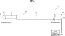
- Fig. 1 shows a front elevational view of a plasma guide wire 10
- Fig. 2 shows a cross-sectional view along A-A of Fig. 1
- Fig. 3 shows an enlarged view of the portion B of Fig. 2 .
- the plasma guide wire 10 includes a guide wire body 20 and an insulating resin tube 30 covering the guide wire body 20.
- the plasma guide wire 10 has a total length of, for example, 1,800 to 2,000 mm.
- the plasma guide wire 10 may also be referred to as a high-frequency (RF) guide wire.
- the guide wire body 20 includes a core shaft 22, a coil 24, a coil-core shaft joining region 25, and a tip 26.
- the core shaft 22 is composed of an electrically conductive material, and includes a shaft rear-end portion 22a and a shaft front-end portion 22b.
- the shaft front-end portion 22b has alternately disposed tubular and tapered portions, and a tubular portion arranged closer to the front end has a smaller diameter.
- the core shaft 22 is composed of a material such as, for example, stainless steel (austenite-based stainless steel, martensite-based stainless steel, ferrite-based stainless steel, austenite-ferrite duplex stainless steel, precipitation-hardening stainless steel, and the like), a superelastic alloy (a Ni-Ti alloy and the like), a piano wire, and tungsten.
- the coil 24 includes a single element wire spirally wound around on the outer periphery of a region at the front end side of the core shaft 22.
- the coil 24 may serve to confer flexibility on the plasma guide wire 10.
- An electric current from a high frequency generator 40 will flow thorough the core shaft 22 to reach the coil core shaft joining region 25, and then will branch and flow to the core shaft 22 and the coil 24. Therefore, the electric current flowing through the coil 24 is smaller than that flowing from the rear end of the core shaft 22 to the coil-core shaft joining region 25.
- the total length of the coil 24 is, for example, 40 mm to 50 mm, and the outer diameter of the coil 24 is, for example, 0.24 mm to 0.25 mm, and the diameter of the element wire is, for example, 0.03 to 0.08 mm.
- the element wire is composed of a material such as, for example, stainless steel (austenite-based stainless steel, martensite-based stainless steel, ferrite-based stainless steel, austenite-ferrite duplex stainless steel, precipitation-hardening stainless steel, and the like), a superelastic alloy (a Ni-Ti alloy and the like), and a radiopacity metal (platinum, gold, tungsten, and the like).
- stainless steel austenite-based stainless steel, martensite-based stainless steel, ferrite-based stainless steel, austenite-ferrite duplex stainless steel, precipitation-hardening stainless steel, and the like
- a superelastic alloy a Ni-Ti alloy and the like
- a radiopacity metal platinum, gold, tungsten, and the like.
- the coil 24 may be formed by spirally winding a plurality of element wires. Further, the coil 24 may be formed by spirally winding a stranded wire having a plurality of element wires twisted.
- the coil-core shaft joining region 25 joins the rear end of the coil 24 with the core shaft 22, and is composed of a solder material.
- Solder materials include, for example, aluminum-alloy solder, silver solder, gold solder, zinc, Sn-Pb alloys, Pb-Ag alloys, Sn-Ag alloys, and the like. It is noted that the coil 24 may also be joined to the core shaft 22 through a solder material at the front end of the coil 24 and/or the middle portion of the coil 24 in addition to at the rear end of the coil 24.
- the tip 26 is a member having a curved surface and formed by welding the front end of the core shaft 22 and the front end of the coil 24.
- arc welding is preferred.
- arc welding may be of non-consumable electrode types such as TIG welding and plasma welding, or may be of consumable electrode types such as coated arc welding, MAG welding, CO 2 gas arc welding, argon-CO 2 gas arc welding, MIG welding, and submerged arc welding.
- Non-consumable electrode types are, however, preferred, and TIG welding is more preferred.
- the insulating resin tube 30 includes a first insulating resin tube 31, a second insulating resin tube 32, and a third insulating resin tube 33.
- the first insulating resin tube 31 is disposed on the outer periphery of the coil 24, and extends from the tip 26 to the rearward of the coil-core shaft joining region 25. The front end of the first insulating resin tube 31 is joined to the tip 26.
- the first insulating resin tube 31 is composed of, for example, a fluorine-based resin (PFA).
- PFA fluorine-based resin
- the total length of the first insulating resin tube 31 is, for example, 100 mm to 115 mm, and the outer diameter of the first insulating resin tube 31 is, for example, 0.3 mm to 0.35 mm, and the thickness of the first insulating resin tube 31 is, for example, 0.015 mm to 0.02 mm.
- the second insulating resin tube 32 is disposed on the outer periphery of the core shaft 22, and extends from the rear end of the first insulating resin tube 31 to the rearward of the core shaft 22.
- the second insulating resin tube 32 is bonded with the first insulating resin tube 31 through a joining region 34.
- the joining region 34 is formed by bonding the inner surface of the second insulating resin tube 32 at the front end with the outer surface of the first insulating resin tube 31 at the rear end via an adhesive.
- Adhesives include, for example, epoxy resin, acrylic resin, and the like.
- the second insulating resin tube 32 is composed of, for example, polyimide resin.
- the total length of the second insulating resin tube 32 is, for example, 1800 mm to 1900 mm, and the outer diameter of the second insulating resin tube 32 is, for example, 0.32 mm to 0.36 mm, and the thickness of the second insulating resin tube 32 is, for example, 0.005 mm to 0.015 mm.
- the second insulating resin tube 32 is harder than the first insulating resin tube 31. It is noted that the joining region 34 may be bonded with the core shaft 22 via an adhesive.
- the third insulating resin tube 33 is arranged inside the first insulating resin tube 31.
- the front end of the third insulating resin tube 33 comes into contact with the coil-core shaft joining region 25.
- the third insulating resin tube 33 is disposed so as to cover throughout a region X of the inner periphery of the first insulating resin tube 31, the region X being located rearwardly relative to a position P facing the rear end of the coil 24.
- the third insulating resin tube 33 further extends to the rearward of the rear end of the first insulating resin tube 31, and covers, from the inside, the joining region 34 between the first insulating resin tube 31 between the second insulating resin tube 32.
- the third insulating resin tube 33 can serve to prevent the first insulating resin tube 31 from making contact with the core shaft 22.
- the third insulating resin tube 33 is composed of, for example, polyimide resin.
- the total length of the third insulating resin tube 33 is, for example, 60 mm to 80 mm, and the outer diameter of the third insulating resin tube 33 is, for example, 0.23 mm to 0.24 mm, and the thickness of the third insulating resin tube 33 is, for example, 0.015 mm to 0.02 mm.
- the third insulating resin tube 33 is harder than the first insulating resin tube 31.
- the third insulating resin tube 33 may have a front end and a rear end bonded with the core shaft 22 via an adhesive.
- the plasma guide wire 10 which can serve as a medical mechanical device for use in percutaneous transluminal coronary angioplasty (PCI), may be used for guiding a device such as a balloon and a stent to an occluded portion of a blood vessel.
- PCI percutaneous transluminal coronary angioplasty
- the front end portion of the core shaft 22 corresponds to the distal portion
- the rear end portion of the core shaft 22 corresponds to the proximal portion.
- the distal portion of the plasma guide wire 10 is inserted into a blood vessel, and the proximal portion is operated by an operator such as a physician.
- an operator pushes, pulls, and/or rotates the plasma guide wire 10 so that the tip 26 may penetrate the occluded portion.
- these operations alone may not be sufficient enough to penetrate the occluded portion if the occluded portion is hardened due to calcification.
- a separate plasma guide wire 10 may be introduced into the blood vessel from the opposite side to place the tip 26 of the separate plasma guide wire 10 in the side opposite to the occluded portion. This leads to a state where a pair of the tips 26 are arranged to be opposed to each other across the occluded portion. High-frequency voltage is then applied between the pair of tips 26 to generate plasma between the pair of tips 26, thereby destroying the occluded portion.
- a stiffness gap may be created in the plasma guide wire 10 at a portion of the relatively soft first insulating resin tubes 31 where the coil 24 is not present, but the stiffness gap can be reduced by virtue of the presence of the third insulating resin tube 33. This can prevent bending at this portion. Further, the third insulating resin tube 33 is not disposed on a portion of the relatively soft first insulating resin tubes 31 where the relatively soft first insulating resin tubes 31 covers the coil 24. This can improve the operativity of the front end side of the plasma guide wire 10, i.e., a portion of the core shaft 22 where the coil 24 is wound around.
- the operativity of the front end side of the plasma guide wire 10 can be improved (i.e., a portion of the core shafts 22 where the coil 24 is wound around or/and a portion of the first insulating resin tube where the coil is not present).
- the first insulating resin tube 31 which is relatively soft and thus has low thermal resistance, may not be able to maintain insulation when making direct contact with the core shaft 22 which is heated to high temperature due to the flow of high-frequency current.
- the third insulating resin tube 33 can serve to prevent the first insulating resin tube 31 from making contact with the core shaft 22. Therefore, insulation of the first insulating resin tube 31 can be better ensured. It is noted that the first insulating resin tube 31 may actually make contact with the coil 24, but the coil 24 is unlikely to be heated to such high temperature. Therefore, insulation will not be compromised. This is because an electric current flowing through the coil 24 upon plasma generation is smaller than that flowing from the rear end of the core shaft 22 through the coil-core shaft joining region 25.
- the third insulating resin tube 33 which is harder than the first insulating resin tube 31, can further reduce the stiffness gap created at a portion of the first insulating resin tubes 31 where the coil 24 is not present.
- the third insulating resin tube 33 which is disposed so as to cover, from the inside, the joining region 34 between the first insulating resin tube 31 and the second insulating resin tube 32, can better ensure insulation at the joining region.
- the third insulating resin tube 33 which comes into contact with the coil-core shaft joining region 25 under a large electric load due to the confluence of an electric current flowing through the coil 24 and an electric current flowing through the core shaft 22, can better ensure insulation at the coil-core shaft joining region 25.
- the third insulating resin tube 33 which is disposed throughout at the region X of the inner periphery of the first insulating resin tube 31, the region X being located rearwardly relative to the position P facing the rear end of the coil 24, can further reduce the stiffness gap created at a portion of the first insulating resin tube 31 where the coil 24 is not present, and can also better ensure insulation of the first insulating resin tube 31.
- the third insulating resin tube 33 is disposed throughout at the region X of the inner periphery of the first insulating resin tube 31, the region X being located rearwardly relative to the position P facing the rear end of the coil 24.
- the third insulating resin tube 33 may be disposed at a portion of the region X.
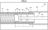
- the third insulating resin tube 33 may be divided into third insulating resin tubes 35, 36, 37 as shown in Fig. 4 . It is noted that in Fig. 4 , the same reference symbols are given to the same components as the aforementioned embodiments.
- the stiffness gap at a portion of the first insulating resin tubes 31 where the coil 24 is not present can be reduced by virtue of the presence of the third insulating resin tubes 35, 36, 37. This can prevent bending at this portion.
- the third insulating resin tubes 35, 36, 37 are not disposed on a portion of the first insulating resin tubes 31 where the first insulating resin tubes 31 covers the coil 24. This can improve the operativity of the front end side of the plasma guide wire 10, i.e., a portion of the core shaft 22 where the coil 24 is wound around. It is not noted that the third insulating resin tubes 35, 36, 37 are preferably disposed so as to prevent the first insulating resin tube 31 from making contact with the core shaft 22.
- any one or two of the third insulating resin tubes 35, 36, 37 may be used.
- the third insulating resin tube 35 insulation at the coil-core shaft joining region 25 can be better ensured.
- the third insulating resin tube 37 insulation at the joining region 34 can be better ensured.
- the tip 26 of the plasma guide wire 10 and the tip 26 of the separate plasma guide wire 10 are arranged to be opposed to each other across an occluded portion inside a blood vessel, and then plasma is generated between the pair of the tips 26 while that state is maintained.
- plasma may be generated by another way.
- plasma may be generated between the tip 26 of the plasma guide wire 10 inserted into a patient's blood vessel and an electrode arranged on the patient's skin.
- two of the plasma guide wires 10 are delivered through a blood vessel in a parallel fashion, and plasma may be generated between the tips 26 of them near an occluded portion to destroy the occluded portion.
- a collar 38 having a ring-like shape and composed of a heat resistant resin may be disposed at the front end of the first insulating resin tube 31, and the collar 38 may be joined to the tip 26 as shown in Fig. 5 .
- a heat resistant resin for example, polyimide resin and others
- the second insulating resin tube 32 may extend to the end face of the shaft rear-end portion 22a.
- a portion of the shaft rear-end portion 22a of the core shaft 22, the portion being not coated with the second insulating resin tube 32 may be coated with another insulating resin tube (a fourth insulating resin tube).
- one harder than the first insulating resin tube 31 is used as the third insulating resin tube 33.
- the configuration shall not be limited to this.
- one having the same hardness as the first insulating resin tube 31 may be used as the third insulating resin tube 33, or one softer than the first insulating resin tube 31 may be used. Even if these configurations are used, the stiffness gap at a portion of the first insulating resin tubes 31 where the coil 24 is not present can be reduced, leading to improved operativity of the front end side of the plasma guide wire 10.
- one harder than the first insulating resin tube 31 is preferably used as the third insulating resin tube 33 because the stiffness gap can be further reduced.
- a material harder than that of the first insulating resin tube 31 is used for the third insulating resin tube 33.
- the material shall not be limited to this.
- one made of the same material as first insulating resin tube 31 but thicker than the first insulating resin tube 31 may be used as the third insulating resin tube 33.
- the third insulating resin tube 33 can be made harder than the first insulating resin tube 31.
- the hardness for the materials of the first insulating resin tube 31, the second insulating resin tube 32, and the third insulating resin tube 33 means the hardness in terms of Shore hardness or the hardness in terms of durometer hardness. Therefore, the hardness for these materials can be measured using a known testing machine.
- plasma guide wire according to an embodiment of the present invention can also be configured, without limitation but for example, as follows.
- the third insulating resin tube may be disposed so as to prevent the first insulating resin tube from making contact with the core shaft.
- a softer resin tends to have lower thermal resistance while a harder resin tends to have higher thermal resistance.
- the first insulating resin tube which is relatively soft and thus has low thermal resistance, may not be able to maintain insulation when making direct contact with the core shaft which is heated to high temperature due to the flow of high-frequency current.
- the third insulating resin tube is disposed so as to prevent the first insulating resin tube from making contact with the core shaft, leading to better ensured insulation of the first insulating resin tube.
- the third insulating resin tube may be harder than the first insulating resin tube. This can further reduce the stiffness gap created at a portion of the first insulating resin tube where the coil is not present.
- the third insulating resin tube may be disposed so as to cover a joining position between the first insulating resin tube and the second insulating resin tube. This can better ensure insulation at the joining position between the first insulating resin tube and the second insulating resin tube.
- the third insulating resin tube may come into contact with the coil-core shaft joining region.
- This configuration where the third insulating resin tube comes into contact with the coil-core shaft joining region under a large electric load due to the confluence of an electric current flowing through the coil and an electric current flowing through the core shaft, can better ensure insulation at the coil-core shaft joining region.
- the third insulating resin tube may be disposed throughout at a region of the inner periphery of the first insulating resin tube, the region being located rearwardly relative to a position facing the rear end of the coil. This can further reduce the stiffness gap created at a portion of the first insulating resin tube where the coil is not present, and can also better ensure insulation of the first insulating resin tube.
- the present invention can be implemented as a medical mechanical device for use in, for example, percutaneous transluminal coronary angioplasty (PCI).
- PCI percutaneous transluminal coronary angioplasty
- PLASMA GUIDE WIRE 20 GUIDE WIRE BODY, 22 CORE SHAFT, 22A SHAFT REAR-END PORTION, 22B SHAFT FRONT-END PORTION, 24 COIL, 25 COIL-CORE SHAFT JOINING REGION, 26 TIP, 30 INSULATING RESIN TUBE ,31 FIRST INSULATING-RESIN TUBE, 32 SECOND INSULATING RESIN TUBE, 33 THIRD INSULATING RESIN TUBE, 34 JOINING REGION, 35, 36, 37 THIRD INSULATING RESIN TUBE, 38 COLLAR, 40 HIGH FREQUENCY GENERATOR, 100 PLASMA GUIDE WIRE, 120 GUIDE WIRE BODY, 122 CORE SHAFT, 124 COIL, 125 COIL-CORE SHAFT JOINING REGION, 126 TIP, 130 INSULATING RESIN TUBE, 131 FIRST INSULATING RESIN TUBE,
Landscapes
- Health & Medical Sciences (AREA)
- Life Sciences & Earth Sciences (AREA)
- Surgery (AREA)
- Engineering & Computer Science (AREA)
- Animal Behavior & Ethology (AREA)
- General Health & Medical Sciences (AREA)
- Veterinary Medicine (AREA)
- Public Health (AREA)
- Biomedical Technology (AREA)
- Heart & Thoracic Surgery (AREA)
- Medical Informatics (AREA)
- Molecular Biology (AREA)
- Nuclear Medicine, Radiotherapy & Molecular Imaging (AREA)
- Physics & Mathematics (AREA)
- Otolaryngology (AREA)
- Plasma & Fusion (AREA)
- Orthopedic Medicine & Surgery (AREA)
- Vascular Medicine (AREA)
- Biophysics (AREA)
- Pulmonology (AREA)
- Anesthesiology (AREA)
- Hematology (AREA)
- Media Introduction/Drainage Providing Device (AREA)
- Surgical Instruments (AREA)
Abstract
[Solution] Provided is a plasma guide wire comprising a core shaft, a coil, a tip, a coil-core shaft joining region, and the first to third insulating resin tubes. The first insulating resin tube is disposed on the outer periphery of the coil, and extends from the tip to the rearward of the coil-core shaft joining region. The second insulating resin tube is disposed on the outer periphery of the core shaft, and joined to the rear end of the first insulating resin tube, and extends from the rear end of the first insulating resin tube to the rearward of the core shaft. The second insulating resin tube is harder than the first insulating resin tube. The third insulating resin tube is disposed on at least a portion of a region of the inner periphery of the first insulating resin tube, the region being located rearwardly relative to a location facing the rear end of the coil.
Description
- The present invention relates to a plasma guide wire.
- Conventionally, plasma guide wires are known. For example, Patent Document 1 discloses a
plasma guide wire 100 as shown inFig. 6 including aguide wire body 120 and aninsulating resin tube 130 covering theguide wire body 120. In theguide wire body 120, acoil 124 is wound around on the outer periphery of a region at the front end side of acore shaft 122, and atip 126 is joined to the front end of thecore shaft 122 and the front end of thecoil 124. The rear end of thecoil 124 is joined to thecore shaft 122 at a coil-coreshaft joining region 125. Theinsulating resin tube 130 includes a firstinsulating resin tube 131 and a secondinsulating resin tube 132. The firstinsulating resin tube 131 is disposed on the outer periphery of thecoil 124, and extends from thetip 126 to the rearward of the coil-coreshaft joining region 125. The secondinsulating resin tube 132 is disposed on the outer periphery of thecore shaft 122, and joined to the rear end of the firstinsulating resin tube 131, and extends from the rear end of the firstinsulating resin tube 131 to the rearward of thecore shaft 122. Theplasma guide wire 100 as described above may be used to generate plasma between the front end of thetip 126 and an electrode of a separate member facing that front end when a high-frequency generator is connected to the rear end of thecore shaft 122. This enables plasma to perforate an occluded portion of a blood vessel. - Patent Document 1:
WO2016/134152 - Nonetheless, a configuration where the first
insulating resin tube 131 and the secondinsulating resin tube 132 are composed of different materials is not mentioned in any way in Patent Document 1. Consequently, the operativity of a portion of theguide wire body 120 where thecoil 124 is wound around may be decreased if the first insulatingresin tube 131 and the secondinsulating resin tube 132 are composed of the same relatively hard resin. On the other hand, a stiffness gap may be created at a portion of the firstinsulating resin tube 131 where thecoil 124 is not present if the secondinsulating resin tube 132 is configured to be softer than the firstinsulating resin tubes 131. This may result in the following problem: the firstinsulating resin tube 131, which is soft, may be bend at this portion when theplasma guide wire 100 is pushed to the front-end direction. This, in turn, will decrease operativity. - The present invention is made to order to solve the problem as described above. A main object of the present invention is to improve operativity of a front end side (that is, a portion of a core shaft where a coil is wound around or/and a portion of a first insulating resin tube where a coil is not present) of a plasma guide wire.
- A plasma guide wire according to an aspect of the present invention includes:
- a core shaft,
- a coil wound around on an outer periphery of a region of a front end side of the core shaft,
- a tip joined to a front end of the core shaft and a front end of the coil,
- a coil-core shaft joining region joining a rear end of the coil with the core shaft,
- a first insulating resin tube disposed on an outer periphery of the coil and extending from the tip to a rearward of the coil-core shaft joining region,
- a second insulating resin tube disposed on an outer periphery of the core shaft, and joined to a rear end of the first insulating resin tube, and extending from the rear end of the first insulating resin tube to a rearward of the core shaft, the second insulating resin tube being harder than the first insulating resin tube, and
- a third insulating resin tube disposed on at least a portion of a region of an inner periphery of the first insulating resin tube, the region being located rearwardly relative to a position facing the rear end of the coil.
- According to the above plasma guide wire, a stiffness gap created at a portion of the relatively soft first insulating resin tube where the coil is not present can be reduced by virtue of the presence of the third insulating resin tube. This can prevent bending at this portion. Further, the third insulating resin tube is not disposed at a portion of the relatively soft first insulating resin tube where the relatively soft first insulating resin tube covers the coil. This can improve the operativity of the front end side of the plasma guide wire, i.e., a portion of the core shaft where the coil is wound around and/or a portion of the first insulating resin tube where the coil is not present.
-
-
Fig. 1 shows a front elevational view of aplasma guide wire 10. -
Fig. 2 shows a cross-sectional view along A-A ofFig. 1 . -
Fig. 3 shows an enlarged view of the portion B ofFig. 2 . -
Fig. 4 shows an explanatory diagram of another embodiment. -
Fig. 5 shows an explanatory diagram of another embodiment. -
Fig. 6 shows a cross-sectional view of a conventionalplasma guide wire 100. - Below, the suitable embodiments of the present invention will be described with reference to the figures.
Fig. 1 shows a front elevational view of aplasma guide wire 10, andFig. 2 shows a cross-sectional view along A-A ofFig. 1 , andFig. 3 shows an enlarged view of the portion B ofFig. 2 . - As shown in
Fig. 1 , theplasma guide wire 10 according to the present embodiment includes aguide wire body 20 and aninsulating resin tube 30 covering theguide wire body 20. Theplasma guide wire 10 has a total length of, for example, 1,800 to 2,000 mm. Theplasma guide wire 10 may also be referred to as a high-frequency (RF) guide wire. - As shown in
Fig. 2 , theguide wire body 20 includes acore shaft 22, acoil 24, a coil-coreshaft joining region 25, and atip 26. - The
core shaft 22 is composed of an electrically conductive material, and includes a shaft rear-end portion 22a and a shaft front-end portion 22b. The shaft front-end portion 22b has alternately disposed tubular and tapered portions, and a tubular portion arranged closer to the front end has a smaller diameter. Thecore shaft 22 is composed of a material such as, for example, stainless steel (austenite-based stainless steel, martensite-based stainless steel, ferrite-based stainless steel, austenite-ferrite duplex stainless steel, precipitation-hardening stainless steel, and the like), a superelastic alloy (a Ni-Ti alloy and the like), a piano wire, and tungsten. - The
coil 24 includes a single element wire spirally wound around on the outer periphery of a region at the front end side of thecore shaft 22. Thecoil 24 may serve to confer flexibility on theplasma guide wire 10. An electric current from ahigh frequency generator 40 will flow thorough thecore shaft 22 to reach the coil coreshaft joining region 25, and then will branch and flow to thecore shaft 22 and thecoil 24. Therefore, the electric current flowing through thecoil 24 is smaller than that flowing from the rear end of thecore shaft 22 to the coil-coreshaft joining region 25. The total length of thecoil 24 is, for example, 40 mm to 50 mm, and the outer diameter of thecoil 24 is, for example, 0.24 mm to 0.25 mm, and the diameter of the element wire is, for example, 0.03 to 0.08 mm. The element wire is composed of a material such as, for example, stainless steel (austenite-based stainless steel, martensite-based stainless steel, ferrite-based stainless steel, austenite-ferrite duplex stainless steel, precipitation-hardening stainless steel, and the like), a superelastic alloy (a Ni-Ti alloy and the like), and a radiopacity metal (platinum, gold, tungsten, and the like). It is noted that thecoil 24 may be formed by spirally winding a plurality of element wires. Further, thecoil 24 may be formed by spirally winding a stranded wire having a plurality of element wires twisted. - The coil-core
shaft joining region 25 joins the rear end of thecoil 24 with thecore shaft 22, and is composed of a solder material. Solder materials include, for example, aluminum-alloy solder, silver solder, gold solder, zinc, Sn-Pb alloys, Pb-Ag alloys, Sn-Ag alloys, and the like. It is noted that thecoil 24 may also be joined to thecore shaft 22 through a solder material at the front end of thecoil 24 and/or the middle portion of thecoil 24 in addition to at the rear end of thecoil 24. - The
tip 26 is a member having a curved surface and formed by welding the front end of thecore shaft 22 and the front end of thecoil 24. For welding, arc welding is preferred. Further, arc welding may be of non-consumable electrode types such as TIG welding and plasma welding, or may be of consumable electrode types such as coated arc welding, MAG welding, CO2 gas arc welding, argon-CO2 gas arc welding, MIG welding, and submerged arc welding. Non-consumable electrode types are, however, preferred, and TIG welding is more preferred. - As shown in
Fig. 2 , the insulatingresin tube 30 includes a first insulatingresin tube 31, a second insulatingresin tube 32, and a third insulatingresin tube 33. - The first insulating
resin tube 31 is disposed on the outer periphery of thecoil 24, and extends from thetip 26 to the rearward of the coil-coreshaft joining region 25. The front end of the first insulatingresin tube 31 is joined to thetip 26. The first insulatingresin tube 31 is composed of, for example, a fluorine-based resin (PFA). The total length of the first insulatingresin tube 31 is, for example, 100 mm to 115 mm, and the outer diameter of the first insulatingresin tube 31 is, for example, 0.3 mm to 0.35 mm, and the thickness of the first insulatingresin tube 31 is, for example, 0.015 mm to 0.02 mm. - The second insulating
resin tube 32 is disposed on the outer periphery of thecore shaft 22, and extends from the rear end of the first insulatingresin tube 31 to the rearward of thecore shaft 22. The second insulatingresin tube 32 is bonded with the first insulatingresin tube 31 through a joiningregion 34. The joiningregion 34 is formed by bonding the inner surface of the second insulatingresin tube 32 at the front end with the outer surface of the first insulatingresin tube 31 at the rear end via an adhesive. Adhesives include, for example, epoxy resin, acrylic resin, and the like. The second insulatingresin tube 32 is composed of, for example, polyimide resin. The total length of the second insulatingresin tube 32 is, for example, 1800 mm to 1900 mm, and the outer diameter of the second insulatingresin tube 32 is, for example, 0.32 mm to 0.36 mm, and the thickness of the second insulatingresin tube 32 is, for example, 0.005 mm to 0.015 mm. The second insulatingresin tube 32 is harder than the first insulatingresin tube 31. It is noted that the joiningregion 34 may be bonded with thecore shaft 22 via an adhesive. - The third insulating
resin tube 33 is arranged inside the first insulatingresin tube 31. The front end of the third insulatingresin tube 33 comes into contact with the coil-coreshaft joining region 25. As shown inFig. 3 , the third insulatingresin tube 33 is disposed so as to cover throughout a region X of the inner periphery of the first insulatingresin tube 31, the region X being located rearwardly relative to a position P facing the rear end of thecoil 24. The third insulatingresin tube 33 further extends to the rearward of the rear end of the first insulatingresin tube 31, and covers, from the inside, the joiningregion 34 between the first insulatingresin tube 31 between the second insulatingresin tube 32. The third insulatingresin tube 33 can serve to prevent the first insulatingresin tube 31 from making contact with thecore shaft 22. The third insulatingresin tube 33 is composed of, for example, polyimide resin. The total length of the third insulatingresin tube 33 is, for example, 60 mm to 80 mm, and the outer diameter of the third insulatingresin tube 33 is, for example, 0.23 mm to 0.24 mm, and the thickness of the third insulatingresin tube 33 is, for example, 0.015 mm to 0.02 mm. The third insulatingresin tube 33 is harder than the first insulatingresin tube 31. The third insulatingresin tube 33 may have a front end and a rear end bonded with thecore shaft 22 via an adhesive. - Next, an exemplary use of the
plasma guide wire 10. Theplasma guide wire 10, which can serve as a medical mechanical device for use in percutaneous transluminal coronary angioplasty (PCI), may be used for guiding a device such as a balloon and a stent to an occluded portion of a blood vessel. In theplasma guide wire 10, the front end portion of thecore shaft 22 corresponds to the distal portion, and the rear end portion of thecore shaft 22 corresponds to the proximal portion. The distal portion of theplasma guide wire 10 is inserted into a blood vessel, and the proximal portion is operated by an operator such as a physician. Once the distal portion reaches an occluded portion in a blood vessel, an operator pushes, pulls, and/or rotates theplasma guide wire 10 so that thetip 26 may penetrate the occluded portion. However, these operations alone may not be sufficient enough to penetrate the occluded portion if the occluded portion is hardened due to calcification. If that is the case, a separateplasma guide wire 10 may be introduced into the blood vessel from the opposite side to place thetip 26 of the separateplasma guide wire 10 in the side opposite to the occluded portion. This leads to a state where a pair of thetips 26 are arranged to be opposed to each other across the occluded portion. High-frequency voltage is then applied between the pair oftips 26 to generate plasma between the pair oftips 26, thereby destroying the occluded portion. - Here, a stiffness gap may be created in the
plasma guide wire 10 at a portion of the relatively soft first insulatingresin tubes 31 where thecoil 24 is not present, but the stiffness gap can be reduced by virtue of the presence of the third insulatingresin tube 33. This can prevent bending at this portion. Further, the third insulatingresin tube 33 is not disposed on a portion of the relatively soft first insulatingresin tubes 31 where the relatively soft first insulatingresin tubes 31 covers thecoil 24. This can improve the operativity of the front end side of theplasma guide wire 10, i.e., a portion of thecore shaft 22 where thecoil 24 is wound around. - In the
plasma guide wire 10 according to the present embodiment as described above, the operativity of the front end side of theplasma guide wire 10 can be improved (i.e., a portion of thecore shafts 22 where thecoil 24 is wound around or/and a portion of the first insulating resin tube where the coil is not present). - Further, a softer resin generally tends to have lower thermal resistance while a harder resin tends to have higher thermal resistance. The first insulating
resin tube 31, which is relatively soft and thus has low thermal resistance, may not be able to maintain insulation when making direct contact with thecore shaft 22 which is heated to high temperature due to the flow of high-frequency current. However, the third insulatingresin tube 33 can serve to prevent the first insulatingresin tube 31 from making contact with thecore shaft 22. Therefore, insulation of the first insulatingresin tube 31 can be better ensured. It is noted that the first insulatingresin tube 31 may actually make contact with thecoil 24, but thecoil 24 is unlikely to be heated to such high temperature. Therefore, insulation will not be compromised. This is because an electric current flowing through thecoil 24 upon plasma generation is smaller than that flowing from the rear end of thecore shaft 22 through the coil-coreshaft joining region 25. - Further, the third insulating
resin tube 33, which is harder than the first insulatingresin tube 31, can further reduce the stiffness gap created at a portion of the first insulatingresin tubes 31 where thecoil 24 is not present. - Still further, the third insulating
resin tube 33, which is disposed so as to cover, from the inside, the joiningregion 34 between the first insulatingresin tube 31 and the second insulatingresin tube 32, can better ensure insulation at the joining region. - Yet further, the third insulating
resin tube 33, which comes into contact with the coil-coreshaft joining region 25 under a large electric load due to the confluence of an electric current flowing through thecoil 24 and an electric current flowing through thecore shaft 22, can better ensure insulation at the coil-coreshaft joining region 25. - Even further, the third insulating
resin tube 33, which is disposed throughout at the region X of the inner periphery of the first insulatingresin tube 31, the region X being located rearwardly relative to the position P facing the rear end of thecoil 24, can further reduce the stiffness gap created at a portion of the first insulatingresin tube 31 where thecoil 24 is not present, and can also better ensure insulation of the first insulatingresin tube 31. - It is noted that the present invention shall not be limited to the aforementioned embodiments, and the present invention can be implemented according to various aspects as long as they fall within the technical scope of the present invention.
- According to the aforementioned embodiments, the third insulating
resin tube 33 is disposed throughout at the region X of the inner periphery of the first insulatingresin tube 31, the region X being located rearwardly relative to the position P facing the rear end of thecoil 24. However, the third insulatingresin tube 33 may be disposed at a portion of the region X. For example, the third insulatingresin tube 33 may be divided into third insulatingresin tubes Fig. 4 . It is noted that inFig. 4 , the same reference symbols are given to the same components as the aforementioned embodiments. Even in the case of this configuration, the stiffness gap at a portion of the first insulatingresin tubes 31 where thecoil 24 is not present can be reduced by virtue of the presence of the third insulatingresin tubes resin tubes resin tubes 31 where the first insulatingresin tubes 31 covers thecoil 24. This can improve the operativity of the front end side of theplasma guide wire 10, i.e., a portion of thecore shaft 22 where thecoil 24 is wound around. It is not noted that the third insulatingresin tubes resin tube 31 from making contact with thecore shaft 22. Further, any one or two of the third insulatingresin tubes resin tube 35 is used, insulation at the coil-coreshaft joining region 25 can be better ensured. When the third insulatingresin tube 37 is used, insulation at the joiningregion 34 can be better ensured. - In the aforementioned embodiments, the
tip 26 of theplasma guide wire 10 and thetip 26 of the separateplasma guide wire 10 are arranged to be opposed to each other across an occluded portion inside a blood vessel, and then plasma is generated between the pair of thetips 26 while that state is maintained. However, plasma may be generated by another way. For example, plasma may be generated between thetip 26 of theplasma guide wire 10 inserted into a patient's blood vessel and an electrode arranged on the patient's skin. Alternatively, two of theplasma guide wires 10 are delivered through a blood vessel in a parallel fashion, and plasma may be generated between thetips 26 of them near an occluded portion to destroy the occluded portion. - In the aforementioned embodiments, a
collar 38 having a ring-like shape and composed of a heat resistant resin (for example, polyimide resin and others) may be disposed at the front end of the first insulatingresin tube 31, and thecollar 38 may be joined to thetip 26 as shown inFig. 5 . It is noted that inFig. 5 , the same reference symbols are given to the same components as the aforementioned embodiments. This configuration can prevent heat damage of the front end of the first insulatingresin tube 31. - In the aforementioned embodiments, the second insulating
resin tube 32 may extend to the end face of the shaft rear-end portion 22a. Alternatively, a portion of the shaft rear-end portion 22a of thecore shaft 22, the portion being not coated with the second insulatingresin tube 32, may be coated with another insulating resin tube (a fourth insulating resin tube). - In the aforementioned embodiments, one harder than the first insulating
resin tube 31 is used as the third insulatingresin tube 33. However, the configuration shall not be limited to this. For example, one having the same hardness as the first insulatingresin tube 31 may be used as the third insulatingresin tube 33, or one softer than the first insulatingresin tube 31 may be used. Even if these configurations are used, the stiffness gap at a portion of the first insulatingresin tubes 31 where thecoil 24 is not present can be reduced, leading to improved operativity of the front end side of theplasma guide wire 10. However, one harder than the first insulatingresin tube 31 is preferably used as the third insulatingresin tube 33 because the stiffness gap can be further reduced. - In the aforementioned embodiments, a material harder than that of the first insulating
resin tube 31 is used for the third insulatingresin tube 33. However, the material shall not be limited to this. For example, one made of the same material as first insulatingresin tube 31 but thicker than the first insulatingresin tube 31 may be used as the third insulatingresin tube 33. Even if this configuration is used, the third insulatingresin tube 33 can be made harder than the first insulatingresin tube 31. It is noted that the hardness for the materials of the first insulatingresin tube 31, the second insulatingresin tube 32, and the third insulatingresin tube 33 means the hardness in terms of Shore hardness or the hardness in terms of durometer hardness. Therefore, the hardness for these materials can be measured using a known testing machine. - It is noted that the plasma guide wire according to an embodiment of the present invention can also be configured, without limitation but for example, as follows.
- In the plasma guide wire according to an embodiment of the present invention, the third insulating resin tube may be disposed so as to prevent the first insulating resin tube from making contact with the core shaft. In general, a softer resin tends to have lower thermal resistance while a harder resin tends to have higher thermal resistance. The first insulating resin tube, which is relatively soft and thus has low thermal resistance, may not be able to maintain insulation when making direct contact with the core shaft which is heated to high temperature due to the flow of high-frequency current. Here, the third insulating resin tube is disposed so as to prevent the first insulating resin tube from making contact with the core shaft, leading to better ensured insulation of the first insulating resin tube.
- In the plasma guide wire according to an embodiment of the present invention, the third insulating resin tube may be harder than the first insulating resin tube. This can further reduce the stiffness gap created at a portion of the first insulating resin tube where the coil is not present.
- In the plasma guide wire according to an embodiment of the present invention, the third insulating resin tube may be disposed so as to cover a joining position between the first insulating resin tube and the second insulating resin tube. This can better ensure insulation at the joining position between the first insulating resin tube and the second insulating resin tube.
- In the plasma guide wire according to an embodiment of the present invention, the third insulating resin tube may come into contact with the coil-core shaft joining region. This configuration where the third insulating resin tube comes into contact with the coil-core shaft joining region under a large electric load due to the confluence of an electric current flowing through the coil and an electric current flowing through the core shaft, can better ensure insulation at the coil-core shaft joining region.
- In the plasma guide wire according to an embodiment of the present invention, the third insulating resin tube may be disposed throughout at a region of the inner periphery of the first insulating resin tube, the region being located rearwardly relative to a position facing the rear end of the coil. This can further reduce the stiffness gap created at a portion of the first insulating resin tube where the coil is not present, and can also better ensure insulation of the first insulating resin tube.
- The present invention can be implemented as a medical mechanical device for use in, for example, percutaneous transluminal coronary angioplasty (PCI).
- 10 PLASMA GUIDE WIRE, 20 GUIDE WIRE BODY, 22 CORE SHAFT, 22A SHAFT REAR-END PORTION, 22B SHAFT FRONT-END PORTION, 24 COIL, 25 COIL-CORE SHAFT JOINING REGION, 26 TIP, 30 INSULATING RESIN TUBE ,31 FIRST INSULATING-RESIN TUBE, 32 SECOND INSULATING RESIN TUBE, 33 THIRD INSULATING RESIN TUBE, 34 JOINING REGION, 35, 36, 37 THIRD INSULATING RESIN TUBE, 38 COLLAR, 40 HIGH FREQUENCY GENERATOR, 100 PLASMA GUIDE WIRE, 120 GUIDE WIRE BODY, 122 CORE SHAFT, 124 COIL, 125 COIL-CORE SHAFT JOINING REGION, 126 TIP, 130 INSULATING RESIN TUBE, 131 FIRST INSULATING RESIN TUBE, 132 SECOND INSULATING RESIN TUBE.
Claims (7)
- A plasma guide wire (10), comprising:a core shaft (22);a coil (24) wound around on an outer periphery of a region of a front end side of the core shaft (22);a tip (26) joined to a front end of the core shaft (22) and a front end of the coil (24);a coil-core shaft joining region (25) joining a rear end of the coil (24) with the core shaft (22);a first insulating resin tube (31) disposed on an outer periphery of the coil (24); anda third insulating resin tube (33 -Fig. 3; 35, 36, 37 -Fig. 4);characterized in thatthe first insulating resin tube (31) extends from the tip (26) to a portion located rearwardly and away from the rear end of the coil (24); andthe third insulating resin tube (33 -Fig. 3; 35, 36, 37 -Fig. 4) is disposed on at least a portion of a region of an inner periphery of the first insulating resin tube (31), the region being located rearwardly relative to a position facing the rear end of the coil (24), the third insulating resin tube (33 -Fig. 3; 35, 36, 37 -Fig. 4) being harder than the first insulating resin tube (31).
- The plasma guide wire (10) according to claim 1, wherein the third insulating resin tube (33 -Fig. 3; 35, 36, 37 - Fig. 4) is disposed so as to prevent the first insulating resin tube (31) from making contact with the core shaft (22).
- The plasma guide wire (10) according to claim 1 or 2, wherein the third insulating resin tube (33 -Fig. 3; 35, 36, 37 - Fig. 4) extends rearwardly relative to the rear end of the first insulating resin tube (31).
- The plasma guide wire (10) according to claim 3, further comprising a second insulating resin tube (32) disposed on an outer periphery of the core shaft (22), wherein the second insulating resin tube (32) extends rearwardly relative to the rear end of the first insulating resin tube (31) to a rear end side of the core shaft (22).
- The plasma guide wire (10) according to claim 4, wherein the second insulating resin tube (32) is harder than the first insulating resin tube (31).
- The plasma guide wire (10) according to any one of claims 1 to 5, wherein the third insulating resin tube (33 -Fig. 3; 35, 36, 37 - Fig. 4) is disposed throughout at the region of the inner periphery of the first insulating resin tube (31), the region being located rearwardly relative to the position facing the rear end of the coil (24).
- The plasma guide wire (10) according to any one of claims 1 to 6, wherein the tip (26) is formed by welding the front end of the core shaft (22) and the front end of the coil (24).
Priority Applications (1)
| Application Number | Priority Date | Filing Date | Title |
|---|---|---|---|
| EP23202090.9A EP4279006A3 (en) | 2017-06-29 | 2017-06-29 | Plasma guide wire |
Applications Claiming Priority (3)
| Application Number | Priority Date | Filing Date | Title |
|---|---|---|---|
| EP23202090.9A EP4279006A3 (en) | 2017-06-29 | 2017-06-29 | Plasma guide wire |
| EP17915536.1A EP3646808A4 (en) | 2017-06-29 | 2017-06-29 | Plasma guide wire |
| PCT/JP2017/023928 WO2019003382A1 (en) | 2017-06-29 | 2017-06-29 | Plasma guide wire |
Related Parent Applications (1)
| Application Number | Title | Priority Date | Filing Date |
|---|---|---|---|
| EP17915536.1A Division EP3646808A4 (en) | 2017-06-29 | 2017-06-29 | Plasma guide wire |
Publications (2)
| Publication Number | Publication Date |
|---|---|
| EP4279006A2 true EP4279006A2 (en) | 2023-11-22 |
| EP4279006A3 EP4279006A3 (en) | 2024-02-21 |
Family
ID=64741212
Family Applications (2)
| Application Number | Title | Priority Date | Filing Date |
|---|---|---|---|
| EP17915536.1A Withdrawn EP3646808A4 (en) | 2017-06-29 | 2017-06-29 | Plasma guide wire |
| EP23202090.9A Withdrawn EP4279006A3 (en) | 2017-06-29 | 2017-06-29 | Plasma guide wire |
Family Applications Before (1)
| Application Number | Title | Priority Date | Filing Date |
|---|---|---|---|
| EP17915536.1A Withdrawn EP3646808A4 (en) | 2017-06-29 | 2017-06-29 | Plasma guide wire |
Country Status (5)
| Country | Link |
|---|---|
| US (1) | US11653970B2 (en) |
| EP (2) | EP3646808A4 (en) |
| JP (1) | JP6724251B2 (en) |
| CN (1) | CN110831532B (en) |
| WO (1) | WO2019003382A1 (en) |
Families Citing this family (3)
| Publication number | Priority date | Publication date | Assignee | Title |
|---|---|---|---|---|
| WO2020246037A1 (en) * | 2019-06-07 | 2020-12-10 | 朝日インテック株式会社 | Guidewire |
| JP7770906B2 (en) * | 2021-12-22 | 2025-11-17 | 朝日インテック株式会社 | Plasma Guidewire |
| JP2023169523A (en) * | 2022-05-17 | 2023-11-30 | 朝日インテック株式会社 | plasma guide wire |
Citations (1)
| Publication number | Priority date | Publication date | Assignee | Title |
|---|---|---|---|---|
| WO2016134152A1 (en) | 2015-02-18 | 2016-08-25 | Retrovascular, Inc. | Radiofrequency guidewire with controlled plasma generation and methods of use thereof |
Family Cites Families (29)
| Publication number | Priority date | Publication date | Assignee | Title |
|---|---|---|---|---|
| US5368035A (en) * | 1988-03-21 | 1994-11-29 | Boston Scientific Corporation | Ultrasound imaging guidewire |
| US4955862A (en) * | 1989-05-22 | 1990-09-11 | Target Therapeutics, Inc. | Catheter and catheter/guide wire device |
| EP0626823B1 (en) * | 1992-02-21 | 2000-04-19 | Boston Scientific Limited | Ultrasound imaging guidewire |
| US5372144A (en) * | 1992-12-01 | 1994-12-13 | Scimed Life Systems, Inc. | Navigability improved guidewire construction and method of using same |
| US5658264A (en) * | 1994-11-10 | 1997-08-19 | Target Therapeutics, Inc. | High performance spiral-wound catheter |
| WO1997024978A1 (en) * | 1996-01-11 | 1997-07-17 | Intella Interventional Systems | Guide wire with adjustable stiffness and method |
| US6251086B1 (en) * | 1999-07-27 | 2001-06-26 | Scimed Life Systems, Inc. | Guide wire with hydrophilically coated tip |
| US6402706B2 (en) * | 1998-12-30 | 2002-06-11 | Advanced Cardiovascular Systems, Inc. | Guide wire with multiple polymer jackets over distal and intermediate core sections |
| US10820925B2 (en) * | 2003-01-21 | 2020-11-03 | Baylis Medical Company Inc. | Transseptal needle |
| US7112197B2 (en) * | 2003-01-21 | 2006-09-26 | Baylis Medical Company Inc. | Surgical device with pressure monitoring ability |
| JP4677205B2 (en) * | 2003-07-17 | 2011-04-27 | テルモ株式会社 | Guide wire |
| JP4455002B2 (en) * | 2003-10-06 | 2010-04-21 | オリンパス株式会社 | High frequency knife |
| CN101001658A (en) * | 2004-08-10 | 2007-07-18 | 株式会社钟化 | Catheter tube for medical treatment and method of manufacturing the same |
| CN1939551B (en) * | 2005-09-28 | 2012-01-18 | 朝日印帝克股份有限公司 | Medical leading wire and manufacture thereof |
| WO2008034010A2 (en) * | 2006-09-13 | 2008-03-20 | Boston Scientific Limited | Crossing guidewire |
| IL181760A0 (en) * | 2007-03-07 | 2007-07-04 | Ran Carmeli | Medical device |
| US9283034B2 (en) * | 2007-09-26 | 2016-03-15 | Retrovascular, Inc. | Recanalization system using radiofrequency energy |
| JP5248932B2 (en) * | 2008-06-20 | 2013-07-31 | 株式会社パイオラックスメディカルデバイス | Guide wire and manufacturing method thereof |
| WO2011033881A1 (en) * | 2009-09-15 | 2011-03-24 | オリンパスメディカルシステムズ株式会社 | High-frequency treatment tool |
| JP4913198B2 (en) * | 2009-10-27 | 2012-04-11 | 株式会社パテントストラ | Medical guide wire, method for manufacturing medical guide wire, assembly of medical guide wire, microcatheter and guiding catheter, and assembly of medical guide wire, balloon catheter and guiding catheter |
| JP4889062B2 (en) * | 2010-02-19 | 2012-02-29 | 朝日インテック株式会社 | Guide wire |
| CN102441222A (en) * | 2010-10-08 | 2012-05-09 | 北京天地和协科技有限公司 | Coaxial composite wire and manufacturing method and application thereof |
| US9186149B2 (en) * | 2010-10-12 | 2015-11-17 | Boston Scientific Scimed, Inc. | Vaso-occlusive device |
| JP2014236757A (en) * | 2011-09-29 | 2014-12-18 | テルモ・クリニカルサプライ株式会社 | Guide wire |
| JP2013106854A (en) * | 2011-11-22 | 2013-06-06 | Asahi Intecc Co Ltd | Guidewire |
| JP6104884B2 (en) * | 2012-03-16 | 2017-03-29 | テルモ株式会社 | Guide wire |
| JP5404840B2 (en) * | 2012-03-29 | 2014-02-05 | 日本ライフライン株式会社 | Medical guidewire |
| EP4032491B1 (en) * | 2013-03-14 | 2025-08-20 | Boston Scientific Medical Device Limited | Electrosurgical device having a lumen |
| JP6722350B2 (en) * | 2017-04-20 | 2020-07-15 | 朝日インテック株式会社 | catheter |
-
2017
- 2017-06-29 WO PCT/JP2017/023928 patent/WO2019003382A1/en not_active Ceased
- 2017-06-29 JP JP2019526063A patent/JP6724251B2/en active Active
- 2017-06-29 CN CN201780092569.7A patent/CN110831532B/en active Active
- 2017-06-29 EP EP17915536.1A patent/EP3646808A4/en not_active Withdrawn
- 2017-06-29 EP EP23202090.9A patent/EP4279006A3/en not_active Withdrawn
-
2019
- 2019-11-08 US US16/677,758 patent/US11653970B2/en active Active
Patent Citations (1)
| Publication number | Priority date | Publication date | Assignee | Title |
|---|---|---|---|---|
| WO2016134152A1 (en) | 2015-02-18 | 2016-08-25 | Retrovascular, Inc. | Radiofrequency guidewire with controlled plasma generation and methods of use thereof |
Also Published As
| Publication number | Publication date |
|---|---|
| JPWO2019003382A1 (en) | 2019-11-07 |
| US11653970B2 (en) | 2023-05-23 |
| JP6724251B2 (en) | 2020-07-15 |
| CN110831532A (en) | 2020-02-21 |
| EP3646808A1 (en) | 2020-05-06 |
| EP3646808A4 (en) | 2021-01-13 |
| CN110831532B (en) | 2023-03-21 |
| US20200069361A1 (en) | 2020-03-05 |
| WO2019003382A1 (en) | 2019-01-03 |
| EP4279006A3 (en) | 2024-02-21 |
Similar Documents
| Publication | Publication Date | Title |
|---|---|---|
| CN104857613B (en) | Guide wire | |
| JP5954748B2 (en) | catheter | |
| CN104519818A (en) | Electrode catheter and method for manufacturing same | |
| US11653970B2 (en) | Plasma guide wire | |
| CN111683716A (en) | Catheter and method of making the same | |
| JP2012130392A (en) | Electrode catheter | |
| US20230090889A1 (en) | Guide wire | |
| EP2921197B1 (en) | Guidewire | |
| US11484687B2 (en) | Catheter | |
| JP6200140B2 (en) | Electrode catheter | |
| JP5561784B2 (en) | Electrode catheter | |
| JP6918185B2 (en) | Guide wire for plasma | |
| CN111163832B (en) | Guide wire | |
| EP3744379B1 (en) | Catheter | |
| US9855407B2 (en) | Guide wire | |
| EP4438099B1 (en) | Guide wire | |
| JP5174487B2 (en) | catheter | |
| JP6219805B2 (en) | Electrode catheter | |
| JP2023169523A (en) | plasma guide wire | |
| HK1184401B (en) | Catheter | |
| HK1184401A1 (en) | Catheter | |
| JP2016096874A (en) | Electrode catheter |
Legal Events
| Date | Code | Title | Description |
|---|---|---|---|
| PUAI | Public reference made under article 153(3) epc to a published international application that has entered the european phase |
Free format text: ORIGINAL CODE: 0009012 |
|
| STAA | Information on the status of an ep patent application or granted ep patent |
Free format text: STATUS: REQUEST FOR EXAMINATION WAS MADE |
|
| 17P | Request for examination filed |
Effective date: 20231006 |
|
| AC | Divisional application: reference to earlier application |
Ref document number: 3646808 Country of ref document: EP Kind code of ref document: P |
|
| AK | Designated contracting states |
Kind code of ref document: A2 Designated state(s): AL AT BE BG CH CY CZ DE DK EE ES FI FR GB GR HR HU IE IS IT LI LT LU LV MC MK MT NL NO PL PT RO RS SE SI SK SM TR |
|
| PUAL | Search report despatched |
Free format text: ORIGINAL CODE: 0009013 |
|
| AK | Designated contracting states |
Kind code of ref document: A3 Designated state(s): AL AT BE BG CH CY CZ DE DK EE ES FI FR GB GR HR HU IE IS IT LI LT LU LV MC MK MT NL NO PL PT RO RS SE SI SK SM TR |
|
| RIC1 | Information provided on ipc code assigned before grant |
Ipc: A61B 18/14 20060101AFI20240115BHEP |
|
| STAA | Information on the status of an ep patent application or granted ep patent |
Free format text: STATUS: THE APPLICATION IS DEEMED TO BE WITHDRAWN |
|
| 18D | Application deemed to be withdrawn |
Effective date: 20240822 |