EP4278917A1 - Personal protection device - Google Patents
Personal protection device Download PDFInfo
- Publication number
- EP4278917A1 EP4278917A1 EP23174182.8A EP23174182A EP4278917A1 EP 4278917 A1 EP4278917 A1 EP 4278917A1 EP 23174182 A EP23174182 A EP 23174182A EP 4278917 A1 EP4278917 A1 EP 4278917A1
- Authority
- EP
- European Patent Office
- Prior art keywords
- protection device
- elements
- inflatable
- inflatable elements
- adjacent
- Prior art date
- Legal status (The legal status is an assumption and is not a legal conclusion. Google has not performed a legal analysis and makes no representation as to the accuracy of the status listed.)
- Pending
Links
- 238000000926 separation method Methods 0.000 claims abstract description 20
- 239000012530 fluid Substances 0.000 claims description 15
- 238000005304 joining Methods 0.000 claims description 13
- 238000004891 communication Methods 0.000 claims description 12
- 238000009423 ventilation Methods 0.000 claims description 11
- 230000001464 adherent effect Effects 0.000 claims description 5
- 239000012528 membrane Substances 0.000 abstract description 3
- 239000007789 gas Substances 0.000 description 12
- 239000000463 material Substances 0.000 description 7
- 230000004913 activation Effects 0.000 description 4
- 238000004026 adhesive bonding Methods 0.000 description 4
- 230000006835 compression Effects 0.000 description 2
- 238000007906 compression Methods 0.000 description 2
- 238000005516 engineering process Methods 0.000 description 2
- 230000006870 function Effects 0.000 description 2
- 238000003780 insertion Methods 0.000 description 2
- 230000037431 insertion Effects 0.000 description 2
- 238000009940 knitting Methods 0.000 description 2
- 238000004519 manufacturing process Methods 0.000 description 2
- 238000000034 method Methods 0.000 description 2
- 229920001200 poly(ethylene-vinyl acetate) Polymers 0.000 description 2
- 239000004814 polyurethane Substances 0.000 description 2
- 229920002725 thermoplastic elastomer Polymers 0.000 description 2
- 229920001468 Cordura Polymers 0.000 description 1
- 238000005299 abrasion Methods 0.000 description 1
- 230000002411 adverse Effects 0.000 description 1
- DQXBYHZEEUGOBF-UHFFFAOYSA-N but-3-enoic acid;ethene Chemical compound C=C.OC(=O)CC=C DQXBYHZEEUGOBF-UHFFFAOYSA-N 0.000 description 1
- 230000001419 dependent effect Effects 0.000 description 1
- 238000001514 detection method Methods 0.000 description 1
- 238000007688 edging Methods 0.000 description 1
- 230000000694 effects Effects 0.000 description 1
- 239000005038 ethylene vinyl acetate Substances 0.000 description 1
- 239000004744 fabric Substances 0.000 description 1
- 239000001307 helium Substances 0.000 description 1
- 229910052734 helium Inorganic materials 0.000 description 1
- SWQJXJOGLNCZEY-UHFFFAOYSA-N helium atom Chemical compound [He] SWQJXJOGLNCZEY-UHFFFAOYSA-N 0.000 description 1
- 238000007731 hot pressing Methods 0.000 description 1
- 238000005192 partition Methods 0.000 description 1
- 229920002635 polyurethane Polymers 0.000 description 1
- 230000009993 protective function Effects 0.000 description 1
- 238000007789 sealing Methods 0.000 description 1
- 210000000323 shoulder joint Anatomy 0.000 description 1
- 229920002994 synthetic fiber Polymers 0.000 description 1
- 239000004753 textile Substances 0.000 description 1
- 239000002699 waste material Substances 0.000 description 1
Images


Classifications
-
- A—HUMAN NECESSITIES
- A41—WEARING APPAREL
- A41D—OUTERWEAR; PROTECTIVE GARMENTS; ACCESSORIES
- A41D13/00—Professional, industrial or sporting protective garments, e.g. surgeons' gowns or garments protecting against blows or punches
- A41D13/015—Professional, industrial or sporting protective garments, e.g. surgeons' gowns or garments protecting against blows or punches with shock-absorbing means
- A41D13/018—Professional, industrial or sporting protective garments, e.g. surgeons' gowns or garments protecting against blows or punches with shock-absorbing means inflatable automatically
-
- A—HUMAN NECESSITIES
- A41—WEARING APPAREL
- A41D—OUTERWEAR; PROTECTIVE GARMENTS; ACCESSORIES
- A41D13/00—Professional, industrial or sporting protective garments, e.g. surgeons' gowns or garments protecting against blows or punches
- A41D13/015—Professional, industrial or sporting protective garments, e.g. surgeons' gowns or garments protecting against blows or punches with shock-absorbing means
- A41D13/0158—Professional, industrial or sporting protective garments, e.g. surgeons' gowns or garments protecting against blows or punches with shock-absorbing means having ventilation features
-
- A—HUMAN NECESSITIES
- A41—WEARING APPAREL
- A41D—OUTERWEAR; PROTECTIVE GARMENTS; ACCESSORIES
- A41D2300/00—Details of garments
- A41D2300/20—Inserts
- A41D2300/24—Folded inserts
-
- A—HUMAN NECESSITIES
- A41—WEARING APPAREL
- A41D—OUTERWEAR; PROTECTIVE GARMENTS; ACCESSORIES
- A41D2400/00—Functions or special features of garments
- A41D2400/10—Heat retention or warming
- A41D2400/14—Heat retention or warming inflatable
-
- A—HUMAN NECESSITIES
- A41—WEARING APPAREL
- A41D—OUTERWEAR; PROTECTIVE GARMENTS; ACCESSORIES
- A41D31/00—Materials specially adapted for outerwear
- A41D31/04—Materials specially adapted for outerwear characterised by special function or use
- A41D31/06—Thermally protective, e.g. insulating
-
- A—HUMAN NECESSITIES
- A41—WEARING APPAREL
- A41D—OUTERWEAR; PROTECTIVE GARMENTS; ACCESSORIES
- A41D31/00—Materials specially adapted for outerwear
- A41D31/04—Materials specially adapted for outerwear characterised by special function or use
- A41D31/14—Air permeable, i.e. capable of being penetrated by gases
Definitions
- the present disclosure relates in general to a personal protection device for protecting a user, wherein the device is preferably of the type which is wearable and/or can be associated with a wearable article, such as a garment.
- the protection device includes in particular an inflatable body which in the inflated condition, is designed to protect from impacts and/or falls a motorcycle rider or passenger or similar user, during a sporting and/or working and/or any other activity.
- the inflatable body is designed to provide protection from the cold.
- a known protection device is, for example, that described in European Patent EP3291697B1 .
- Such a device includes an inflatable element designed to assume an active inflated condition and a deflated rest condition.
- the inflatable element includes a knitted body, namely a body made by means of a knitting process.
- Said knitted body is a closed or at least tubular structure defining an inner region or area or chamber. This inner chamber is occupied at least partially by a plurality of joining threads which connect together opposite portions of the knitted body.
- the fact of providing a single knitted body has the advantage of limiting the manufacturing waste and minimizing the production time; in fact, the joining threads and meshes may be processed using a single knitting machine.
- the joining threads form part of single thread connected to the opposite portions of the knitted body. In particular, the thread passes along alternate sections and continuously between a first portion and a second portion of the knitted body.
- the inflatable element also includes sealing walls which are arranged externally and allow the inflation fluid to be contained for a predetermined period of time.
- the walls consist, for example, of a first sheet, or first wall, and of a second sheet, or second wall, which are fixed together along respective perimetral edges.
- Said first and second sheets made of impermeable material cover and line the knitted body on an outer side or outer surface.
- Such a wearable protection device is known from EP2373189B1 .
- Both the wearable devices have the advantage that they have, in the inflated condition, a flat mattress-like form which is particularly suitable and appropriate for insertion in a garment.
- An inflatable element designed in this manner while being very advantageous from many points of view, nevertheless has the drawback that it covers the body also in the deflated condition and does not always allow suitable breathability in the article of clothing in which it is incorporated or inserted.
- the inflatable element in the deflated condition may create a kind of bag around the user's body which does not allow a suitable throughflow of ventilation air.
- a technical problem underlying the present disclosure is that of providing a protection device for protecting a user, which is configured in such a way that the inflatable body is able to maintain in the inflated condition a substantially mattress-like - and therefore substantially flat - form and at the same time is able to overcome the drawbacks of the prior art and which ensures a greater breathability and/or achieves further advantages.
- the personal protection device includes a mattress body including a plurality of inflatable elements arranged adjacent in sequence, wherein each inflatable element has an elongated envelope - preferably substantially tubular - shape so as to define an internal chamber which is channel-like, namely shaped in the manner of a channel.
- the mattress body is designed to assume a first rest configuration in which the inflatable elements are in a deflated condition close to or stacked on top of each other.
- the mattress body is designed to assume also an active configuration in which said inflatable elements are in an inflated condition.
- the form of the mattress body which, as mentioned, is formed overall by a plurality of tubular elements arranged adjacent in sequence, favours unfolding from the stacked condition into the inflated condition where they are extended and unfolded.
- Each inflatable element has an elongated, preferably tubular, form and therefore the internal channel-shaped chamber, when the inflatable element is substantially inflated, has a form corresponding to the internal hollow zone of a tubular element.
- the tubular elements are in fact narrow and long separate bodies which are joined together in sequence side-by-side. More particularly, they consist of elements which are straight in the inflated condition, namely have a straight and/or rectilinear - and not curved - form. In this way, the tubular elements may easily pass from a compact stacked condition into an extended or unfolded condition in which the inflatable elements are fully expanded so as to obtain the flat-shaped mattress body, with an inflated panel-like configuration.
- each inflatable element has mutual connection zones and separation zones.
- the mutual connection zones are configured to maintain a mutual connection between the adjacent inflatable elements, while the separation zones are configured to maintain a separation between adjacent inflatable elements.
- the separation zones defines a plurality of through-channels passing between adjacent inflatable elements.
- the protection device also includes a covering sleeve or simple cover, which defines an internal zone where the mattress body is housed.
- the set of inflatable elements is therefore lined with at least one cover, or covering sleeve, configured to provide the airbag with greater dimensional stability and therefore resistance to high pressures.
- it may provide greater abrasion resistance and therefore, for example, may be made of a material such as a synthetic fabric, for example Cordura, but may also be made of a material with fireproof/flame-proof properties so as to ensure greater fire resistance.
- it may be formed by a pair of sheets arranged opposite each other and joined together along a respective perimeter or may be a single body.
- the covering sleeve therefore defines an internal zone or region where the mattress body including the plurality of inflatable elements is arranged.
- the device furthermore includes one or more tie elements connected to the covering sleeve and each slidably and/or freely inserted inside a respective through-channel.
- each tie element is not fixed directly to the inflatable elements, but surrounds the outer sleeve so as to help provide the flat form of the mattress body and give the entire device a greater dimensional stability and consequently resistance to high pressures. Owing to the sliding and free insertion inside the respective through-channel, the tie element may adjust the form of the protection device, without however directly acting on the inflatable elements so as to avoid excessive tensioning of the inflatable elements.
- the mutual connection zones are adherence areas.
- the inflatable elements therefore have side walls adhering in pairs and two opposite walls which, once the inflatable elements are joined together, form opposite external surfaces of the mattress body, namely a surface or wall exposed to an impact or to the cold and a rear wall facing the user.
- the two opposite surfaces are substantially flat in the inflated condition.
- the tie elements protrude from the opposite surfaces and are connected to the cover.
- the inflatable element may be easily combined with other protection devices or elements, for example rigid plate-type protection bodies, separate from the inflatable element and having a form matching that of the inflatable element in the inflated condition, or inserted inside the pocket of the wearable article.
- other protection devices or elements for example rigid plate-type protection bodies, separate from the inflatable element and having a form matching that of the inflatable element in the inflated condition, or inserted inside the pocket of the wearable article.
- a further advantage consists in the fact that the tie elements and the partially adhering walls of the inflatable elements ensure a limited expansion of the inflatable element in an inflated condition so as to obtain a smaller overall size, and in particular a limited thickness, while at the same time ensuring adequate protection for a user.
- a wearable article such as a garment, a jacket, a suit or other article of clothing.
- This smaller size moreover ensures, in the event of accidental inflation of the inflatable element, less inconvenience and risk for a user while driving a vehicle. In other words, a limited expansion of the inflatable element does not adversely affect control of a vehicle by the user and therefore does not pose the risk of an accident.
- Another advantage consists in the fact that, by controlling the form of the inflatable element. it is possible to control (and in particular limit) also the amount of gas needed for inflation of the inflatable element.
- the inflatable mattress body is therefore a flexible body which, in the inflated condition, maintains this condition at least for a given time period.
- it consists of a body which is impermeable to an inflation gas.
- a breather valve is provided for deflation of the mattress body.
- a body made of a pressure-resistant material which is able to ensure the gas-tightness for at least a certain period of time, may be used as the material for the mattress body.
- Said material may be, for example, PU (polyurethane), EVA (ethylene vinyl acetate) or TPE (thermoplastic elastomer).
- PU polyurethane
- EVA ethylene vinyl acetate
- TPE thermoplastic elastomer
- These membranes may also be impregnated with non-extensible fine meshes in order to ensure greater tightness of the inflatable elements (in terms of expansion resistance).
- a wall of an inflatable element of the plurality of inflatable elements is fixed so as to adhere only locally to a wall of an adjacent inflatable element of the plurality of inflatable elements, so as to define a mutual connection zone between two adjacent inflatable elements.
- each inflatable element, or part of them includes at least two walls which are joined together along a perimeter so as to define a perimetral joining edge.
- said adherence zone between two adjacent inflatable elements alternates with a perimetral joining edge of the two inflatable element walls.
- the inflatable element is in fact a double-leaf body, namely similar to a body with two flat sheets joined together along the perimeter so as form a long and narrow body. It can be understood that the prechosen geometrical form of an inflatable element with a double leaf joined together along the perimetral edge favours the compression of one wall against another one in the deflated condition like a concertina and at the same time the opening into the inflated condition again in the manner of a concertina.
- the protection device preferably also includes one or more gas sources connected to the inflatable mattress body so as to inflate the mattress body between the deflated condition and the inflated condition.
- the gas source may be housed inside the internal channel-like chamber of an inflatable element.
- the gas source may be a pressurised gas generator or a manual inflation device which can be activated by a user, such as an air pump.
- the inflatable elements may each have independent access to one or more gas sources.
- the adjacent inflatable elements are in fluid communication with each other for common inflation.
- the mattress body includes through-holes or fluid communication holes in the adhering walls of two said adjacent inflatable elements so as to provide the fluid communication.
- an inflation device comprising a fluid generator may be arranged outside the inflatable elements and connected there in fluid communication by means of a suitable connection.
- the protection device can be housed in a receiving area of the garment or in a garment portion.
- Said portion is understood as being a garment portion which covers a part of the body, such as the torso (neck region, chest region, shoulder joint region, back and arms).
- the garment portion includes said layer and is made using a predefined textile technology able to provide the garment with given properties, such as breathability, or with ventilation openings.
- wearable article is understood as meaning any article or portion thereof which may be worn by a user, such as an article of clothing, a garment or other wearable accessory.
- the wearable article includes a protection device such as that described above and at least one layer defining a zone for receiving the body of a user, i.e. intended to receive the body of a user for a protective function, whether it be protection from impacts or protection from the cold or the like.
- the protection device is associated with said layer, on one side, which may be identified as the inner layer of said layer, facing said receiving area.
- the layer of the wearable article also has a breathability property or has at least one ventilation opening.
- the receiving area includes a first part and a second part open towards the first part, and the breathability property or ventilation opening is associated at least with said second part of the receiving area so as to allow ventilation at least in said second part.
- the mattress body performs its protection function in the inflated condition, while ventilation and breathability may be ensured when the mattress body is in the deflated condition.
- the second part of the receiving area is configured to receive the mattress body in the extended and inflated condition, while it remains free to allow breathability when the mattress body is in the rest configuration.
- the mattress body occupies both said first part of the receiving area and said second part of the receiving area and preferably the whole of the second part of the receiving area.
- the mattress body occupies only the first part of the receiving area. Consequently, once housed inside the garment and the mattress body is in the deflated condition, the second part of the receiving area, which is normally devoid of mattress body, is able to allow the breathability and ventilation of the garment.
- the reference number 100 indicates a wearable article, in the present case a waistcoat, including a personal protection device 10 according to the present disclosure in accordance with a respective embodiment of the present disclosure.
- a portion of the wearable article 100 for example the chest portion, or back portion, according to the present disclosure includes at least one layer 11 defining an area for receiving the body of a user.
- the layer is a layer of the waistcoat or a lining of the waistcoat.
- the layer 11 is to be understood as being a layer of the waistcoat, in general, made of fabric or other material. Preferably, as will be explained more clearly below, at least part of the layer 11 allows breathability and the entry of air inside the wearable article 100.
- the waistcoat or similar wearable article 100 includes an area - indicated by means of broken lines and the reference number 12 - which is intended to receive the body of a user for a protection function, whether it be protection from impacts, protection from the cold, or any other kind of protection.
- the receiving area 12 is, in the embodiment shown, an area intended to receive the torso of a user.
- the layer 11 also has, as mentioned, a breathability property or has at least one ventilation opening 15.
- the protection device 10 is associated with said layer 11, on an inner side of said layer towards the receiving area, as shown in Figures 7 and 8 .
- the personal protection device 10 includes a mattress body 16, including a plurality of inflatable elements 18, arranged adjacent in sequence, wherein each inflatable element has the form of a long and narrow envelope, preferably tubular shaped, i.e. in the form of a closed tube, so as to each define an internal chamber 19 shaped like a channel.
- the inflatable elements 18 and the respective internal chambers 19 are preferably in fluid communication by means of through-holes so as to form a single inflation chamber for said inflatable elements 18.
- the inflatable elements 18 which form the mattress body 16 are identical to each other in terms of shape and size, namely they all have the same form and the same dimensions.
- the inflatable elements 19 may have a different shape and/or size, for example at least one of the inflatable elements 18 may have dimensions greater than or smaller than other inflatable elements 18 of the mattress body 16, or may be shaped differently from other inflatable elements 18 of the mattress body 16.
- the inflatable elements 18 may be organized or grouped together in groups of inflatable elements, wherein each group of inflatable elements may comprise, or group together, inflatable elements 18 with the same shape and/or size.
- the inflatable elements 18 may be grouped together in at least two groups in which the inflatable elements of each group have dimensions greater than or smaller than those of the inflatable elements of another group.
- the tubular-shaped elements 18 of one group may have a height and/or diameter greater or smaller than the inflatable elements 18 of another group.
- Each group of inflatable elements may also be arranged alongside and/or associated with a further group of inflatable elements.
- a first group of inflatable elements with a first shape and/or size may be associated with or arranged alongside a second group of inflatable elements, wherein the second group of inflatable elements comprises inflatable elements with a second shape and/or size, wherein preferably the second shape and/or size is different from the first shape and/or size.
- each inflatable element 18 has at last one mutual connection zone 20 and at least one separation zone 21.
- the mutual connection zones are configured to maintain a mutual connection, namely one where they are joined together and preferably totally adherent, between the adjacent inflatable elements 18, while the separation zones 21 are configured to maintain a separation between adjacent inflatable elements 18. Consequently, the separation zones 21 define a plurality of through-channels 28 passing between adjacent inflatable elements 18.
- the adjacent inflatable elements 18 have mutual connection zones 20 where the adjacent inflatable elements 18 are connected for example by means of gluing together, stitching or similar joining systems, and separation zones 21, where the adjacent inflatable elements 18 are kept separate and/or disconnected.
- at least one through-channel 28 is defined in each of the separation zones 21, so as to define a plurality of through-channels 28 between adjacent inflatable elements 28.
- the set of inflatable elements 18 is also covered by at least one or more membranes or a sheet designed to form a cover 50 or a covering sleeve and provide the mattress body 16 with greater dimensional stability and hence resistance to high pressures.
- the protection device 10 includes a cover 50 which defines an internal zone and said internal zone receives the mattress body 16.
- the device furthermore includes one or more tie elements 52 connected to the cover 50 or covering sleeve and each slidably and/or freely inserted inside a respective through-channel 28 between the inflatable elements 18.
- the one or more tie elements 52 surround(s) the cover 50 and is free to slide with respect to the inflatable elements 18 so as to allow form control (since it is fixed to the cover 50) but without creating a tension on the inflatable elements 18.
- each of the inflatable elements 18 has ta least one side wall 18a, 18b partially adhering to an adjacent side wall 18a, 18b of an adjacent inflatable element and two opposite walls 18c, 18d which, once the sequence of inflatable elements 18 has been defined, form opposite external surfaces, namely a surface or wall exposed to an impact, or to the cold, and a rear wall facing the user.
- the tie elements 52 protrude from the external surface and are connected to the cover 50.
- adherent side walls 18a, 18b of adjacent inflatable elements comprise the mutual connection zones 20, and the separation zones 21, together with the tie elements 52, help to act as components for controlling the form of the protection device 10 between the two external surfaces and to provide control of the mattress or flat form for the mattress body, without creating excessive tension on the tie elements.
- the one or more tie elements 52 are parts of an elongated body such as, for example, a band. Namely a plurality of tie elements 52 are connected together to form an elongated body 53 which, in the outer zones, may also surround the cover 50 on the outside in the manner of a hoop.
- the tie elements 52 are inserted slidably and freely inside the respective through-channels 28 and are also part of an elongated body which may surround on the outside at least partially each of the inflatable elements 18.
- the elongated body 53 may maintain and/or stabilize a desired shape of the inflatable elements 18 in the inflated condition, owing to the fact that it surrounds and encircles the tie elements.
- the inflatable elements have through-channels 28 which are aligned and the elongated body 53 is inserted slidably and/or freely inside aligned through-channels 28 between adjacent inflatable elements 18.
- the inflatable elements 18 have through-channels 28 aligned with each other in rows.
- the elongated body 53 is slidably inserted in a sinusoidal manner from above and from below the group of inflatable elements inside the respective aligned through-channels 28.
- the elongated body portions 53 which are inserted inside the through-channels 28 act as or form the tie element 52.
- the elongated body 53 which forms the tie elements 52 of a series of aligned channels 52 is inserted in a sinusoidal manner in the through-channels 28, namely, once inside the aligned through-channels 28, it may form a sinusoid which surrounds at least partially the inflatable elements 18 on the outside.
- the elongated body 53 has a plurality of connecting elements 52a configured to be associated with each other in a removable manner so as keep the internal band portions in positions corresponding to the one or more tie elements 52 inserted inside said through-channels 28, without the risk of them sliding out.
- the connecting elements 52a may be loops or annular elements which are associated with the one or more tie elements 52 and which may be connected together removably, for example, by means of one or more clasps or hooks 55 or any element suitable for keeping at least two loops or two annular elements joined together.
- the connecting elements 52a may removably connect the one or more tie elements 52 so as to prevent the tie elements 52 from coming out of the respective through-channels 28.
- this configuration not only prevents a fixed connection between the tie elements 52 and the inflatable elements 18, but also avoids having to associate the one or more tie elements 52 with the covering sleeve at too many points, for example by means of stitches, which may be difficult to execute owing to the proximity to the inflatable elements 18.
- a single stitch along the elongated body 53 may be provided, or no stitches and only hooks, fasteners or other locking devices are present.
- the mattress body 16 is designed to assume a first rest configuration in which the inflatable elements 18 are in a deflated condition close to or stacked on top of each other as shown in Figure 7 inside a first part 12a of the receiving area 12 underneath said layer 11, leaving free a second part 12b of the receiving area which is open towards the first part.
- the mattress body 16 is also designed to assume an active configuration in which said inflatable elements 18 are in an inflated condition and occupy both said first part 12a of the receiving area and the second part 12b of said receiving area 12.
- said at least one layer 11 has said breathability property or said ventilation opening 15 at least in said second part 12b of the receiving area 12, and said second part of the receiving area, when the mattress body 1 is in the deflated configuration, is devoid of the mattress body 16.
- the second part 12b of the receiving area 12 is configured to receive the protection device in the extended and inflated condition, while it remains free to allow breathability when the protection device 10 is in the deflated rest configuration.
- the mattress body 16, which overall is formed by a plurality of tubular elements 18 arranged adjacent in sequence, favours the unfolding from the stacked condition, into the extended and unfolded condition. As shown in Figure 8 , in the inflated condition, the mattress body occupies preferably the whole of the second part 12b of the receiving area.
- each inflatable element 18 has a tubular shape and therefore the internal chamber 19, when the inflatable element is substantially inflated, has a channel-like shape corresponding to the empty volume of a tubular element.
- the tubular elements 18 are in fact narrow and long. As can be seen, they are elements which are straight and not curved; in this way, not only when they are extended, the mattress body 16 has a flat shape, but they may also pass easily from a compact stacked condition into an extended condition.
- the inflatable elements 18 therefore have side walls 18a, 18b adhering to each other in pairs and two opposite walls18c, 18d which, once the inflatable elements 18 are joined together, form and act as opposite external surfaces, i.e. a surface or wall exposed to an impact or to the cold and a rear wall facing the user.
- the adjacent side walls 18a, 18b adhering to each other act as tensioning components between the two external surfaces, so as to provide control of the mattress or flat form of the mattress body.
- the mattress body 16 is inflated preferably so as to tension the side walls 18a, 18b which adhere to each other.
- the maximum tension of the tie components determines the maximum distance which is possible between the external surfaces.
- the geometry of the parts described above enables a structure which is as flat as possible to be obtained, and the inflatable elements 18 are arranged alongside each other and at the same time define, by means of the adherent walls 18a, 1b, internal separating walls or partitions suitably arranged so as to create a plurality of housings.
- the mattress body 16 includes through-holes 22 or fluid communication holes in the adherent walls 18a, 18b of two said adjacent inflatable elements, so as to form the fluid communication.
- the holes 22 are formed in the mutual connection zones 20 of the tubular elements 18.
- each inflatable element 18 includes at least two sheets 28, 29 or walls which are joined together along a perimeter so as to define a perimetral joining edge 30, defining for each inflatable element the aforementioned internal chamber 19 in fluid communication with an adjacent internal chamber.
- an adherence area 31 alternates with a perimetral joining edge 30 of the two walls 28, 29 of the inflatable element.
- the inflatable element 18 is in fact therefore a body of the double-leaf type, i.e. it is like a body having two flat sheets which are joined along the perimeter and which form a long and narrow body.
- the joining together of the two walls or sheets 28, 29 may be performed using technology known in the sector, for example by means of gluing and/or by means of suitable edging with tape or by means of spot gluing or gluing along one edge, or by means of hot pressing.
- the protection device 10 may find an application in numerous areas, also for protection of the head.
- the protection device 10 such as that described above, may be curved so as form a kind of "C" or open ring, in order to protect the head.
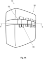
- Figure 14 shows a direction of expansion of the protection device 10, from a deflated condition, in which the inflatable elements are collapsed onto each other, and an inflated condition, in which the inflatable elements are extended so as to create a protection mattress, as described above.
- the protection device 10 may be housed in the collar of an article of clothing, in a backpack or other housing seat and extend upwards so as to protect the head when required.
- the protection device preferably includes also a gas source (not shown) connected to the inflatable mattress body so as to inflate the mattress body 16 between the deflated condition and the inflated condition.
- the gas source may be housed inside an inflatable element.
- the protection device 10 in order to perform inflation of the mattress body, in the event of a sudden fall and/or sliding and/or an impact involving a user or a vehicle being ridden/driven by the user, the protection device 10 is designed to cooperate with special activation means (not shown) which are operationally connected for example to the gas source (as mentioned, not shown), such as a canister containing compressed cold gas, for example helium.
- the canister may be provided with a respective shut-off valve (not shown).
- the inflation fluid source may comprise gas generators preferably of the pyrotechnic or hybrid type or other types known according to the state of the art. Opening of the shut-off valve of each inflation canister is preferably controlled by a control unit depending on the detection of the state of the vehicle/rider system; for example said control unit may implement a system for predicting the fall which allows early identification of the fall event and a reliable prediction of this event by means of accelerometer sensors fixed to the vehicle (or rider) and a unit for processing the signals produced by the said sensors.
- the device according to the present disclosure may also be applied using an activation cable connected to a vehicle ridden/driven by a user, which cable activates inflation of the inflatable element following the movement of the user away from the vehicle, for example following a fall or a sudden impact.
- an activation cable connected to a vehicle ridden/driven by a user, which cable activates inflation of the inflatable element following the movement of the user away from the vehicle, for example following a fall or a sudden impact.
- Use of a cable is employed in particular in the horse-riding sector.
- activation and inflation means may be incorporated in the protection device according to the present invention or located on the outside thereof.
Abstract
A protection device (10) for protecting a user, which can be associated with a wearable article, is described. The protection device (10) includes a mattress body (16) including a plurality of inflatable elements (18) arranged adjacent side-by-side in sequence. Each inflatable element (18) has a tubular form so as to each define an internal chamber (19) shaped like a channel. The mattress body (16) assumes a first rest configuration in which the inflatable elements (18) are in a deflated condition close to or stacked on top of each other. The mattress body (16) also assumes an active configuration in which the inflatable elements (18) are in an inflated condition. Moreover, each inflatable element (18) has mutual connection zones and separation zones, where the mutual connection zones are configured to maintain a mutual connection between inflatable elements (18) adjacent to each other, while the separation zones are configured to maintain a separation between adjacent inflatable elements (18). The separation zones define a plurality of through-channels passing between adjacent inflatable elements (18).The set of inflatable elements (18) is covered by at least one membrane or sheet (50) designed to form a covering sleeve and provide the mattress body (16) with dimensional stability.The device includes one or more tie elements (52) connected to the covering sleeve and each inserted slidably and/or freely inside a respective through-channel.
Description
- The present disclosure relates in general to a personal protection device for protecting a user, wherein the device is preferably of the type which is wearable and/or can be associated with a wearable article, such as a garment.
- It therefore concerns a protection device which preferably forms part of a wearable article, such as a garment or other article of clothing. The protection device includes in particular an inflatable body which in the inflated condition, is designed to protect from impacts and/or falls a motorcycle rider or passenger or similar user, during a sporting and/or working and/or any other activity. Alternatively, the inflatable body is designed to provide protection from the cold.
- A known protection device is, for example, that described in European Patent
EP3291697B1 . Such a device includes an inflatable element designed to assume an active inflated condition and a deflated rest condition. The inflatable element includes a knitted body, namely a body made by means of a knitting process. Said knitted body is a closed or at least tubular structure defining an inner region or area or chamber. This inner chamber is occupied at least partially by a plurality of joining threads which connect together opposite portions of the knitted body. The fact of providing a single knitted body has the advantage of limiting the manufacturing waste and minimizing the production time; in fact, the joining threads and meshes may be processed using a single knitting machine. The joining threads form part of single thread connected to the opposite portions of the knitted body. In particular, the thread passes along alternate sections and continuously between a first portion and a second portion of the knitted body. - The inflatable element also includes sealing walls which are arranged externally and allow the inflation fluid to be contained for a predetermined period of time. The walls consist, for example, of a first sheet, or first wall, and of a second sheet, or second wall, which are fixed together along respective perimetral edges. Said first and second sheets made of impermeable material cover and line the knitted body on an outer side or outer surface.
- Such a wearable protection device is known from
EP2373189B1 . - Both the wearable devices have the advantage that they have, in the inflated condition, a flat mattress-like form which is particularly suitable and appropriate for insertion in a garment. An inflatable element designed in this manner, while being very advantageous from many points of view, nevertheless has the drawback that it covers the body also in the deflated condition and does not always allow suitable breathability in the article of clothing in which it is incorporated or inserted. In particular, the inflatable element in the deflated condition may create a kind of bag around the user's body which does not allow a suitable throughflow of ventilation air.
- A technical problem underlying the present disclosure is that of providing a protection device for protecting a user, which is configured in such a way that the inflatable body is able to maintain in the inflated condition a substantially mattress-like - and therefore substantially flat - form and at the same time is able to overcome the drawbacks of the prior art and which ensures a greater breathability and/or achieves further advantages.
- This problem is solved by a protection device for protecting a user and by wearable article according to the respective independent claims. Secondary characteristic features forming the subject of the present disclosure are defined in the respective dependent claims.
- According to one aspect of the present disclosure, the personal protection device includes a mattress body including a plurality of inflatable elements arranged adjacent in sequence, wherein each inflatable element has an elongated envelope - preferably substantially tubular - shape so as to define an internal chamber which is channel-like, namely shaped in the manner of a channel.
- The mattress body is designed to assume a first rest configuration in which the inflatable elements are in a deflated condition close to or stacked on top of each other. The mattress body is designed to assume also an active configuration in which said inflatable elements are in an inflated condition. The form of the mattress body, which, as mentioned, is formed overall by a plurality of tubular elements arranged adjacent in sequence, favours unfolding from the stacked condition into the inflated condition where they are extended and unfolded.
- Each inflatable element has an elongated, preferably tubular, form and therefore the internal channel-shaped chamber, when the inflatable element is substantially inflated, has a form corresponding to the internal hollow zone of a tubular element. The tubular elements are in fact narrow and long separate bodies which are joined together in sequence side-by-side. More particularly, they consist of elements which are straight in the inflated condition, namely have a straight and/or rectilinear - and not curved - form. In this way, the tubular elements may easily pass from a compact stacked condition into an extended or unfolded condition in which the inflatable elements are fully expanded so as to obtain the flat-shaped mattress body, with an inflated panel-like configuration.
- Furthermore, each inflatable element has mutual connection zones and separation zones. In particular, the mutual connection zones are configured to maintain a mutual connection between the adjacent inflatable elements, while the separation zones are configured to maintain a separation between adjacent inflatable elements. In particular, the separation zones defines a plurality of through-channels passing between adjacent inflatable elements.
- The protection device also includes a covering sleeve or simple cover, which defines an internal zone where the mattress body is housed.
- The set of inflatable elements is therefore lined with at least one cover, or covering sleeve, configured to provide the airbag with greater dimensional stability and therefore resistance to high pressures. Furthermore, it may provide greater abrasion resistance and therefore, for example, may be made of a material such as a synthetic fabric, for example Cordura, but may also be made of a material with fireproof/flame-proof properties so as to ensure greater fire resistance. For example it may be formed by a pair of sheets arranged opposite each other and joined together along a respective perimeter or may be a single body. The covering sleeve therefore defines an internal zone or region where the mattress body including the plurality of inflatable elements is arranged.
- The device furthermore includes one or more tie elements connected to the covering sleeve and each slidably and/or freely inserted inside a respective through-channel.
- In other words, each tie element is not fixed directly to the inflatable elements, but surrounds the outer sleeve so as to help provide the flat form of the mattress body and give the entire device a greater dimensional stability and consequently resistance to high pressures. Owing to the sliding and free insertion inside the respective through-channel, the tie element may adjust the form of the protection device, without however directly acting on the inflatable elements so as to avoid excessive tensioning of the inflatable elements.
- Preferably, the mutual connection zones are adherence areas. The inflatable elements therefore have side walls adhering in pairs and two opposite walls which, once the inflatable elements are joined together, form opposite external surfaces of the mattress body, namely a surface or wall exposed to an impact or to the cold and a rear wall facing the user.
- The two opposite surfaces are substantially flat in the inflated condition. The tie elements protrude from the opposite surfaces and are connected to the cover.
- Consequently, when the mattress element is in the inflated condition, owing to the combination of characteristic features such as:
- the mutually adhering side walls of two adjacent inflatable elements;
- and the tie elements which act as ties between the two external surfaces;
- Owing to the form control, the inflatable element may be easily combined with other protection devices or elements, for example rigid plate-type protection bodies, separate from the inflatable element and having a form matching that of the inflatable element in the inflated condition, or inserted inside the pocket of the wearable article.
- A further advantage consists in the fact that the tie elements and the partially adhering walls of the inflatable elements ensure a limited expansion of the inflatable element in an inflated condition so as to obtain a smaller overall size, and in particular a limited thickness, while at the same time ensuring adequate protection for a user.
- Since it relates in fact to an inflatable device, such a solution is particularly advantageous, for a wearable article, such as a garment, a jacket, a suit or other article of clothing.
- This smaller size moreover ensures, in the event of accidental inflation of the inflatable element, less inconvenience and risk for a user while driving a vehicle. In other words, a limited expansion of the inflatable element does not adversely affect control of a vehicle by the user and therefore does not pose the risk of an accident.
- Another advantage consists in the fact that, by controlling the form of the inflatable element. it is possible to control (and in particular limit) also the amount of gas needed for inflation of the inflatable element.
- The inflatable mattress body is therefore a flexible body which, in the inflated condition, maintains this condition at least for a given time period. Preferably, it consists of a body which is impermeable to an inflation gas. In this case, a breather valve is provided for deflation of the mattress body.
- More particularly, a body made of a pressure-resistant material, which is able to ensure the gas-tightness for at least a certain period of time, may be used as the material for the mattress body. Said material may be, for example, PU (polyurethane), EVA (ethylene vinyl acetate) or TPE (thermoplastic elastomer). These membranes may also be impregnated with non-extensible fine meshes in order to ensure greater tightness of the inflatable elements (in terms of expansion resistance).
- As mentioned, in order to create the mattress body, a wall of an inflatable element of the plurality of inflatable elements is fixed so as to adhere only locally to a wall of an adjacent inflatable element of the plurality of inflatable elements, so as to define a mutual connection zone between two adjacent inflatable elements. Preferably, each inflatable element, or part of them, includes at least two walls which are joined together along a perimeter so as to define a perimetral joining edge. As regards the geometry of the parts described there, along the sequence of adjacent inflatable elements, namely along a direction of expansion of the mattress body or direction of side-by-side arrangement, it may be understood that said adherence zone between two adjacent inflatable elements alternates with a perimetral joining edge of the two inflatable element walls. A mattress body with a concertina-like structure is therefore formed.
- In other words, according to this preferred embodiment, the inflatable element is in fact a double-leaf body, namely similar to a body with two flat sheets joined together along the perimeter so as form a long and narrow body. It can be understood that the prechosen geometrical form of an inflatable element with a double leaf joined together along the perimetral edge favours the compression of one wall against another one in the deflated condition like a concertina and at the same time the opening into the inflated condition again in the manner of a concertina.
- The protection device preferably also includes one or more gas sources connected to the inflatable mattress body so as to inflate the mattress body between the deflated condition and the inflated condition. The gas source may be housed inside the internal channel-like chamber of an inflatable element.
- For example, the gas source may be a pressurised gas generator or a manual inflation device which can be activated by a user, such as an air pump.
- Alternatively, for inflation, the inflatable elements may each have independent access to one or more gas sources. Alternatively, the adjacent inflatable elements are in fluid communication with each other for common inflation. For example, the mattress body includes through-holes or fluid communication holes in the adhering walls of two said adjacent inflatable elements so as to provide the fluid communication. Alternatively, an inflation device comprising a fluid generator may be arranged outside the inflatable elements and connected there in fluid communication by means of a suitable connection.
- The protection device can be housed in a receiving area of the garment or in a garment portion. Said portion is understood as being a garment portion which covers a part of the body, such as the torso (neck region, chest region, shoulder joint region, back and arms). The garment portion includes said layer and is made using a predefined textile technology able to provide the garment with given properties, such as breathability, or with ventilation openings.
- In the continuation of the present disclosure "wearable article" is understood as meaning any article or portion thereof which may be worn by a user, such as an article of clothing, a garment or other wearable accessory.
- Preferably, the wearable article, or a portion thereof, includes a protection device such as that described above and at least one layer defining a zone for receiving the body of a user, i.e. intended to receive the body of a user for a protective function, whether it be protection from impacts or protection from the cold or the like. The protection device is associated with said layer, on one side, which may be identified as the inner layer of said layer, facing said receiving area. The layer of the wearable article also has a breathability property or has at least one ventilation opening.
- The receiving area includes a first part and a second part open towards the first part, and the breathability property or ventilation opening is associated at least with said second part of the receiving area so as to allow ventilation at least in said second part. In the first part of the receiving area and in the second part of the receiving area the mattress body performs its protection function in the inflated condition, while ventilation and breathability may be ensured when the mattress body is in the deflated condition.
- Basically, the second part of the receiving area is configured to receive the mattress body in the extended and inflated condition, while it remains free to allow breathability when the mattress body is in the rest configuration. Expressed in yet other words, in the inflated condition, the mattress body occupies both said first part of the receiving area and said second part of the receiving area and preferably the whole of the second part of the receiving area. In the deflated condition, the mattress body occupies only the first part of the receiving area. Consequently, once housed inside the garment and the mattress body is in the deflated condition, the second part of the receiving area, which is normally devoid of mattress body, is able to allow the breathability and ventilation of the garment.
- Further characteristic features, advantages and modes of use forming the subject of the present disclosure will become clear from the following detailed description of a number of preferred examples of embodiment thereof, provided by way of a nonlimiting example. It is nevertheless evident that each embodiment may have one or more of the advantages listed above; in any case it is nevertheless not necessary that each embodiment should have simultaneously all the advantages listed.
- Reference will be made to the figures of the attached drawings in which:
-
Figure 1A shows a perspective view of a protection device in the inflated condition according to an embodiment of the present disclosure; -
Figure 1B shows a detailed view of the protection device according toFigure 1A ; -
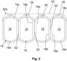
Figure 2 shows a schematic cross-sectional view along the line II-II of the protection device according toFigure 1A ; -
Figure 3 shows a perspective view from the rear of the protection device according toFigure 1A ; -
Figure 4 shows a schematic cross-sectional view along the line IV-IV of the protection device according toFigure 3 ; -
Figure 5 shows a partially transparent schematic view of a garment including a protection device according to the present disclosure in the deflated condition; -
Figure 6 shows a partially transparent schematic view of the garment according toFigure 5 including a protection device according to the present disclosure in the inflated condition; -
Figures 7 and 8 show in schematic form a protection device associated with a layer of a wearable article in the deflated condition and inflated condition, respectively; -
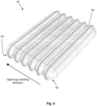
Figure 9 shows an axonometric view of a protection device according to a further embodiment of the present disclosure, in which the covering sleeve and the through-channels are not shown; -
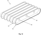
Figure 10 shows a partially sectioned axonometric view of the protection device according toFigure 9 ; -
Figure 11 shows a partially transparent side view of the protection device according toFigure 9 ; -
Figures 12-14 show a corresponding number of views of an application of the protection device according to the present disclosure for protecting the head; -
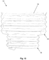
Figures 15 and16 show a top plan and side view, respectively, of an embodiment of a protection device according to the present disclosure. - With reference to the accompanying figures, the
reference number 100 indicates a wearable article, in the present case a waistcoat, including apersonal protection device 10 according to the present disclosure in accordance with a respective embodiment of the present disclosure. - A portion of the
wearable article 100, for example the chest portion, or back portion, according to the present disclosure includes at least onelayer 11 defining an area for receiving the body of a user. The layer is a layer of the waistcoat or a lining of the waistcoat. Thelayer 11 is to be understood as being a layer of the waistcoat, in general, made of fabric or other material. Preferably, as will be explained more clearly below, at least part of thelayer 11 allows breathability and the entry of air inside thewearable article 100. - In other words, the waistcoat or similar
wearable article 100 includes an area - indicated by means of broken lines and the reference number 12 - which is intended to receive the body of a user for a protection function, whether it be protection from impacts, protection from the cold, or any other kind of protection. The receivingarea 12 is, in the embodiment shown, an area intended to receive the torso of a user. - The
layer 11 also has, as mentioned, a breathability property or has at least oneventilation opening 15. Theprotection device 10 is associated with saidlayer 11, on an inner side of said layer towards the receiving area, as shown inFigures 7 and 8 . - More particularly, the
personal protection device 10 includes amattress body 16, including a plurality ofinflatable elements 18, arranged adjacent in sequence, wherein each inflatable element has the form of a long and narrow envelope, preferably tubular shaped, i.e. in the form of a closed tube, so as to each define aninternal chamber 19 shaped like a channel. Theinflatable elements 18 and the respectiveinternal chambers 19 are preferably in fluid communication by means of through-holes so as to form a single inflation chamber for saidinflatable elements 18. - Preferably, the
inflatable elements 18 which form themattress body 16 are identical to each other in terms of shape and size, namely they all have the same form and the same dimensions. - In an alternative embodiment, the
inflatable elements 19 may have a different shape and/or size, for example at least one of theinflatable elements 18 may have dimensions greater than or smaller than otherinflatable elements 18 of themattress body 16, or may be shaped differently from otherinflatable elements 18 of themattress body 16. With particular reference toFigures 15 and16 , for example, theinflatable elements 18 may be organized or grouped together in groups of inflatable elements, wherein each group of inflatable elements may comprise, or group together,inflatable elements 18 with the same shape and/or size. For example, theinflatable elements 18 may be grouped together in at least two groups in which the inflatable elements of each group have dimensions greater than or smaller than those of the inflatable elements of another group. For example, the tubular-shapedelements 18 of one group may have a height and/or diameter greater or smaller than theinflatable elements 18 of another group. Each group of inflatable elements may also be arranged alongside and/or associated with a further group of inflatable elements. For example, a first group of inflatable elements with a first shape and/or size may be associated with or arranged alongside a second group of inflatable elements, wherein the second group of inflatable elements comprises inflatable elements with a second shape and/or size, wherein preferably the second shape and/or size is different from the first shape and/or size. In this way it is possible for themattress body 16 to assume specific or desired shapes and/or obtain a variable thickness, when theinflatable elements 18 are in the deflated or inflated condition. - Furthermore, each
inflatable element 18 has at last onemutual connection zone 20 and at least oneseparation zone 21. In particular, the mutual connection zones are configured to maintain a mutual connection, namely one where they are joined together and preferably totally adherent, between the adjacentinflatable elements 18, while theseparation zones 21 are configured to maintain a separation between adjacentinflatable elements 18. Consequently, theseparation zones 21 define a plurality of through-channels 28 passing between adjacentinflatable elements 18. - In other words, the adjacent
inflatable elements 18 havemutual connection zones 20 where the adjacentinflatable elements 18 are connected for example by means of gluing together, stitching or similar joining systems, andseparation zones 21, where the adjacentinflatable elements 18 are kept separate and/or disconnected. In this way, at least one through-channel 28 is defined in each of theseparation zones 21, so as to define a plurality of through-channels 28 between adjacentinflatable elements 28. - The set of
inflatable elements 18 is also covered by at least one or more membranes or a sheet designed to form acover 50 or a covering sleeve and provide themattress body 16 with greater dimensional stability and hence resistance to high pressures. In other words, theprotection device 10 includes acover 50 which defines an internal zone and said internal zone receives themattress body 16. - The device furthermore includes one or
more tie elements 52 connected to thecover 50 or covering sleeve and each slidably and/or freely inserted inside a respective through-channel 28 between theinflatable elements 18. - In other words, the one or
more tie elements 52 surround(s) thecover 50 and is free to slide with respect to theinflatable elements 18 so as to allow form control (since it is fixed to the cover 50) but without creating a tension on theinflatable elements 18. - As regards the geometry of the parts described above, each of the
inflatable elements 18 has ta least oneside wall adjacent side wall opposite walls inflatable elements 18 has been defined, form opposite external surfaces, namely a surface or wall exposed to an impact, or to the cold, and a rear wall facing the user. Thetie elements 52 protrude from the external surface and are connected to thecover 50. - Furthermore, the
adherent side walls mutual connection zones 20, and theseparation zones 21, together with thetie elements 52, help to act as components for controlling the form of theprotection device 10 between the two external surfaces and to provide control of the mattress or flat form for the mattress body, without creating excessive tension on the tie elements. - According to a preferred embodiment, the one or
more tie elements 52 are parts of an elongated body such as, for example, a band. Namely a plurality oftie elements 52 are connected together to form anelongated body 53 which, in the outer zones, may also surround thecover 50 on the outside in the manner of a hoop. - In other words, the
tie elements 52 are inserted slidably and freely inside the respective through-channels 28 and are also part of an elongated body which may surround on the outside at least partially each of theinflatable elements 18. Theelongated body 53 may maintain and/or stabilize a desired shape of theinflatable elements 18 in the inflated condition, owing to the fact that it surrounds and encircles the tie elements. - Preferably, the inflatable elements have through-
channels 28 which are aligned and theelongated body 53 is inserted slidably and/or freely inside aligned through-channels 28 between adjacentinflatable elements 18. In other words, theinflatable elements 18 have through-channels 28 aligned with each other in rows. Theelongated body 53 is slidably inserted in a sinusoidal manner from above and from below the group of inflatable elements inside the respective aligned through-channels 28. Theelongated body portions 53 which are inserted inside the through-channels 28 act as or form thetie element 52. - Expressed differently, the
elongated body 53 which forms thetie elements 52 of a series of alignedchannels 52 is inserted in a sinusoidal manner in the through-channels 28, namely, once inside the aligned through-channels 28, it may form a sinusoid which surrounds at least partially theinflatable elements 18 on the outside. - According to a preferred embodiment, the
elongated body 53 has a plurality of connectingelements 52a configured to be associated with each other in a removable manner so as keep the internal band portions in positions corresponding to the one ormore tie elements 52 inserted inside said through-channels 28, without the risk of them sliding out. For example, the connectingelements 52a may be loops or annular elements which are associated with the one ormore tie elements 52 and which may be connected together removably, for example, by means of one or more clasps or hooks 55 or any element suitable for keeping at least two loops or two annular elements joined together. In other words, the connectingelements 52a may removably connect the one ormore tie elements 52 so as to prevent thetie elements 52 from coming out of the respective through-channels 28. - Advantageously, this configuration not only prevents a fixed connection between the
tie elements 52 and theinflatable elements 18, but also avoids having to associate the one ormore tie elements 52 with the covering sleeve at too many points, for example by means of stitches, which may be difficult to execute owing to the proximity to theinflatable elements 18. - For example, a single stitch along the
elongated body 53 may be provided, or no stitches and only hooks, fasteners or other locking devices are present. - As mentioned above, according to one aspect of the present disclosure, the
mattress body 16 is designed to assume a first rest configuration in which theinflatable elements 18 are in a deflated condition close to or stacked on top of each other as shown inFigure 7 inside afirst part 12a of the receivingarea 12 underneath saidlayer 11, leaving free asecond part 12b of the receiving area which is open towards the first part. - The
mattress body 16 is also designed to assume an active configuration in which saidinflatable elements 18 are in an inflated condition and occupy both saidfirst part 12a of the receiving area and thesecond part 12b of said receivingarea 12. - Even more particularly, said at least one
layer 11 has said breathability property or saidventilation opening 15 at least in saidsecond part 12b of the receivingarea 12, and said second part of the receiving area, when themattress body 1 is in the deflated configuration, is devoid of themattress body 16. Basically thesecond part 12b of the receivingarea 12 is configured to receive the protection device in the extended and inflated condition, while it remains free to allow breathability when theprotection device 10 is in the deflated rest configuration. Themattress body 16, which overall is formed by a plurality oftubular elements 18 arranged adjacent in sequence, favours the unfolding from the stacked condition, into the extended and unfolded condition. As shown inFigure 8 , in the inflated condition, the mattress body occupies preferably the whole of thesecond part 12b of the receiving area. - As mentioned, each
inflatable element 18 has a tubular shape and therefore theinternal chamber 19, when the inflatable element is substantially inflated, has a channel-like shape corresponding to the empty volume of a tubular element. Thetubular elements 18 are in fact narrow and long. As can be seen, they are elements which are straight and not curved; in this way, not only when they are extended, themattress body 16 has a flat shape, but they may also pass easily from a compact stacked condition into an extended condition. - The
inflatable elements 18 therefore haveside walls inflatable elements 18 are joined together, form and act as opposite external surfaces, i.e. a surface or wall exposed to an impact or to the cold and a rear wall facing the user. As a result, when themattress body 16 is in the inflated condition, theadjacent side walls mattress body 16 is inflated preferably so as to tension theside walls - In particular, the geometry of the parts described above enables a structure which is as flat as possible to be obtained, and the
inflatable elements 18 are arranged alongside each other and at the same time define, by means of theadherent walls 18a, 1b, internal separating walls or partitions suitably arranged so as to create a plurality of housings. - Preferably, in order to achieve the fluid communication, the
mattress body 16 includes through-holes 22 or fluid communication holes in theadherent walls holes 22 are formed in themutual connection zones 20 of thetubular elements 18. - Again preferably, as shown in
Figure 9 in detail, eachinflatable element 18 includes at least twosheets perimetral joining edge 30, defining for each inflatable element the aforementionedinternal chamber 19 in fluid communication with an adjacent internal chamber. As regards the geometry of the parts described there, along the sequence of adjacent inflatable elements, anadherence area 31 alternates with aperimetral joining edge 30 of the twowalls inflatable element 18 is in fact therefore a body of the double-leaf type, i.e. it is like a body having two flat sheets which are joined along the perimeter and which form a long and narrow body. It can be understood that the geometrical form chosen, of an inflatable element with double leaf joined together along theperimetral edge 30, favours the compression of one wall against the other one in the deflated condition or configuration in the manner of a concertina, and at the same time the opening, like said concertina, towards the inflated condition. - The joining together of the two walls or
sheets - It is pointed out that the
protection device 10 according to the present disclosure may find an application in numerous areas, also for protection of the head. In particular, with reference toFigures 12-14 , theprotection device 10, such as that described above, may be curved so as form a kind of "C" or open ring, in order to protect the head.Figure 14 shows a direction of expansion of theprotection device 10, from a deflated condition, in which the inflatable elements are collapsed onto each other, and an inflated condition, in which the inflatable elements are extended so as to create a protection mattress, as described above. In the deflated condition, theprotection device 10 may be housed in the collar of an article of clothing, in a backpack or other housing seat and extend upwards so as to protect the head when required. - It is to be understood that the protection device preferably includes also a gas source (not shown) connected to the inflatable mattress body so as to inflate the
mattress body 16 between the deflated condition and the inflated condition. The gas source may be housed inside an inflatable element. - In particular, in order to perform inflation of the mattress body, in the event of a sudden fall and/or sliding and/or an impact involving a user or a vehicle being ridden/driven by the user, the
protection device 10 is designed to cooperate with special activation means (not shown) which are operationally connected for example to the gas source (as mentioned, not shown), such as a canister containing compressed cold gas, for example helium. The canister may be provided with a respective shut-off valve (not shown). - Alternatively, the inflation fluid source may comprise gas generators preferably of the pyrotechnic or hybrid type or other types known according to the state of the art. Opening of the shut-off valve of each inflation canister is preferably controlled by a control unit depending on the detection of the state of the vehicle/rider system; for example said control unit may implement a system for predicting the fall which allows early identification of the fall event and a reliable prediction of this event by means of accelerometer sensors fixed to the vehicle (or rider) and a unit for processing the signals produced by the said sensors.
- Alternatively, the device according to the present disclosure may also be applied using an activation cable connected to a vehicle ridden/driven by a user, which cable activates inflation of the inflatable element following the movement of the user away from the vehicle, for example following a fall or a sudden impact. Use of a cable is employed in particular in the horse-riding sector.
- In any case the aforementioned activation and inflation means may be incorporated in the protection device according to the present invention or located on the outside thereof.
- It should also be noted that the activation modes, although being an aspect of particular importance for effective operation of the device, will not be further described in greater detail since they are methods which are essentially already known to a person skilled in the art of protection of a person from sudden impacts. The subject-matter of the present disclosure has been described hitherto with reference to its embodiments. It is to be understood that other embodiments relating to the same inventive idea may exist, all of these falling within the scope of protection of the claims which are attached below.
Claims (16)
- Protection device (10) for the personal protection of a user, wherein said device includes a mattress body (16) including a plurality of inflatable elements (18), arranged adjacent side-by-side in sequence, wherein each inflatable element (18) has an elongated envelope shape so as to each define an internal chamber (19) shaped like a channel, and wherein the mattress body (16) is designed to assume a first rest configuration in which the inflatable elements (18) are in a deflated condition close to or stacked on top of each other, and wherein the mattress body (16) is designed to assume an active configuration in which said inflatable elements (18) are in an inflated condition with a straight and/or rectilinear form, wherein each inflatable element (18) has at least one mutual connection zone (20) and at least one separation zone (21), wherein said mutual connection zones (20) are configured to maintain a mutual connection between inflatable elements (18) adjacent to each other and said separation zones (21) are configured to maintain a separation between adjacent inflatable elements (18), and wherein said separation zones (21) define a plurality of through-channels (28) passing between adjacent inflatable elements(18),and wherein the protection device (10) comprises a cover (50) defining an internal zone, the internal zone being configured to receive the mattress body (16),and wherein the device includes one or more tie elements (52) connected to the cover (50) and each inserted slidably and/or freely inside a respective through-channel (28) passing between adjacent inflatable elements (18).
- Protection device (10) according to claim 1, wherein each of the inflatable elements (18) has at least one side wall (18a, 18b) partially adhering to a side wall (18a, 18b) of an adjacent inflatable element and two opposite walls (18c, 18d) which, once the sequence of inflatable elements (18) has been defined, form opposite external surfaces, namely a surface or wall exposed to an impact or to the cold and a rear wall facing the user,
and wherein the partially adhering side walls (18a, 18b) of adjacent inflatable elements comprise said mutual connection zones (20) and said separation zones (21) and said one or more tie elements (52) protrude from opposite sides beyond said two external surfaces and are connected to the cover (50). - Protection device (10) according to any one of the preceding claims, wherein said one or more tie elements (52) are parts of an elongated body (53).
- Protection device (10) according to any one of the preceding claims, wherein the tie elements (52) are part of an elongated body (53) inserted in a sinusoidal arrangement inside respective through-channels (28) passing between adjacent inflatable elements (18).
- Protection device (10) according to the preceding claim, wherein a part of said single elongated body (53) which protrudes from the cover (50) has respective connecting elements (52a) configured to be associated with each other in a removable manner in such a way as to keep remaining portions of said elongated body forming said tie elements (52) inserted inside said through-channels (28).
- Protection device (10) according to the preceding claim, wherein said connecting elements (52a) are associated with each other in a removable manner by means of one or more clasp or hook elements (55).
- Protection device (10) according to claim 4 or 5 or 6, wherein a part of said single elongated body (53) is external to the cover and encircles or surrounds said cover (50).
- Protection device according to claim 4, wherein a plurality of said adjacent inflatable elements (18) have through-channels (28) aligned with each other in rows and said elongated body (53) is slidably inserted in a sinusoidal manner from above and from below the sequence of inflatable elements (18) inside the respective through-channels aligned to form a sinusoid which at least partially surrounds the inflatable elements (18) on the outside and wherein said protection device comprises connecting elements (52a) for joining together adjacent portions of the elongated body (52) which protrude from respective through-channels (28) passing between adjacent inflatable elements (18).
- Protection device (10) according to any one of the preceding claims, wherein the inflatable elements (18) and the respective internal chambers (19) are in fluid communication so as to form a single inflation chamber for said inflatable elements (18).
- Protection device (10) according to any one of the preceding claims, wherein the mattress body (16) includes through-holes (22) or fluid communication holes in the adherent walls (18a, 18b) of two said adjacent inflatable elements, so as to form the fluid communication.
- Protection device (10) according to any one of the preceding claims, wherein each inflatable element (18) or part of the inflatable elements includes at least two walls or sheets (28, 29) joined together along a perimeter so as to define a perimetral joining edge (30) and wherein along the sequence of adjacent inflatable elements (18), an adherence area (31) alternates with a perimetral joining edge (30) of the two walls (28, 29) of the inflatable element (18).
- Protection device (10) according to the preceding claim, wherein said opposite walls (18c, 18d) comprise said perimetral joining edge (30) and wherein said partially adhering side walls (18a, 18b) comprise said adherence area (31).
- Protection device (10) according to any one of the preceding claims, wherein said protection device is an impact protection device, including a pressurised gas source, said protection device being configured to determine said inflated condition in the event of danger or impact.
- Protection device (10) according to any one of the preceding claims 1 to 11, wherein said protection device is a cold protection device, including a gas source, said protection device being configured to determine said inflated condition for protecting a user from the cold.
- Wearable article (100) including a protection device (10) according to any one of the preceding claims.
- Wearable article (100) according to the preceding claim, including at least one layer (11) defining at least partially a receiving area (12) for receiving the body of a user, wherein the layer (11) has a breathability property and/or at least one ventilation opening (15) and wherein said protection device (10) is associated with said layer (11) on one side of said layer towards said receiving area (12), and wherein said receiving area (12) includes a first part (12a) and a second part (12b) open towards the first part (12a) and wherein said breathability property and/or at least one ventilation opening (15) is/are associated at least with said second part (12b); and wherein said inflatable elements occupy in the deflated condition said first part (12a) of the receiving area (12) below said layer (11) and in the inflated condition occupy said first part (12a) of the receiving area and said second part (12b) of said receiving area (12) and wherein a situation in which said second part (12b) of the receiving area (12) is devoid of the mattress body (16) corresponds to a situation in which the mattress body (16) is in said deflated condition.
Applications Claiming Priority (1)
| Application Number | Priority Date | Filing Date | Title |
|---|---|---|---|
| IT202200010424 | 2022-05-19 |
Publications (1)
| Publication Number | Publication Date |
|---|---|
| EP4278917A1 true EP4278917A1 (en) | 2023-11-22 |
Family
ID=82943260
Family Applications (1)
| Application Number | Title | Priority Date | Filing Date |
|---|---|---|---|
| EP23174182.8A Pending EP4278917A1 (en) | 2022-05-19 | 2023-05-18 | Personal protection device |
Country Status (1)
| Country | Link |
|---|---|
| EP (1) | EP4278917A1 (en) |
Citations (6)
| Publication number | Priority date | Publication date | Assignee | Title |
|---|---|---|---|---|
| US3319260A (en) * | 1964-06-10 | 1967-05-16 | Gen Dynamics Corp | Survival garment |
| EP1767108A1 (en) * | 2005-09-21 | 2007-03-28 | Hajdar Ademaj | Inflatable protective garment |
| EP2373189B1 (en) | 2008-12-09 | 2012-07-04 | Dainese S.p.A. | Personal protection device and garment including such a device |
| EP3291697B1 (en) | 2015-05-06 | 2018-12-05 | Dainese S.p.A. | Protection device and method for manufacturing such a protection device |
| WO2021116931A1 (en) * | 2019-12-13 | 2021-06-17 | D-Air Lab S.r.l. | Protective device and method for making said protective device |
| WO2021260002A1 (en) * | 2020-06-26 | 2021-12-30 | Alpinestars Research S.p.A. | Wearable protection device |
-
2023
- 2023-05-18 EP EP23174182.8A patent/EP4278917A1/en active Pending
Patent Citations (6)
| Publication number | Priority date | Publication date | Assignee | Title |
|---|---|---|---|---|
| US3319260A (en) * | 1964-06-10 | 1967-05-16 | Gen Dynamics Corp | Survival garment |
| EP1767108A1 (en) * | 2005-09-21 | 2007-03-28 | Hajdar Ademaj | Inflatable protective garment |
| EP2373189B1 (en) | 2008-12-09 | 2012-07-04 | Dainese S.p.A. | Personal protection device and garment including such a device |
| EP3291697B1 (en) | 2015-05-06 | 2018-12-05 | Dainese S.p.A. | Protection device and method for manufacturing such a protection device |
| WO2021116931A1 (en) * | 2019-12-13 | 2021-06-17 | D-Air Lab S.r.l. | Protective device and method for making said protective device |
| WO2021260002A1 (en) * | 2020-06-26 | 2021-12-30 | Alpinestars Research S.p.A. | Wearable protection device |
Similar Documents
| Publication | Publication Date | Title |
|---|---|---|
| US9554602B2 (en) | Garment combined with a device for the personal protection of a user | |
| CN113194772B (en) | Wearable air bag device | |
| CA2501746C (en) | Life preserver system | |
| EP2727815B1 (en) | A personal protection system including a garment with body armour and a personal flotation device | |
| WO2000051454A8 (en) | Protective garment | |
| EP4072364B1 (en) | Protective device and method for making said protective device | |
| EP3167730B1 (en) | Wearable protection device | |
| CN109068771A (en) | The balloon actuator being mounted in customization buckle for personal anti-collision system | |
| US8998667B2 (en) | Personal floatation device having selectively inflatable bladders | |
| EP1417123B1 (en) | Multi-chambered flotation device | |
| EP3795020B1 (en) | Protection device and process for manufacturing such protection device | |
| US6678895B1 (en) | Protective garment, which is worn with shoulder pad having inflatable bladder, for firefighter or for emergency worker | |
| EP4278917A1 (en) | Personal protection device | |
| KR20240024764A (en) | wearable protective devices | |
| US20150011136A1 (en) | Personal Flotation Device Having Selectively Inflatable Bladders | |
| EP3835140B1 (en) | Protective device and method for manufaturing such protective device | |
| EP4029396A1 (en) | Head protection device | |
| EP4197378A1 (en) | Personal protection device | |
| JPH03128743A (en) | Air bag | |
| EP3434123A1 (en) | Protective device | |
| WO2018197718A1 (en) | Lifejacket | |
| JP7472841B2 (en) | Wearable airbag device | |
| CN2627451Y (en) | Multifunctional bullet-proof vest | |
| JP2004090773A (en) | Continuous wear type life vest and buoyant material for life vest |
Legal Events
| Date | Code | Title | Description |
|---|---|---|---|
| PUAI | Public reference made under article 153(3) epc to a published international application that has entered the european phase |
Free format text: ORIGINAL CODE: 0009012 |
|
| STAA | Information on the status of an ep patent application or granted ep patent |
Free format text: STATUS: THE APPLICATION HAS BEEN PUBLISHED |
|
| AK | Designated contracting states |
Kind code of ref document: A1 Designated state(s): AL AT BE BG CH CY CZ DE DK EE ES FI FR GB GR HR HU IE IS IT LI LT LU LV MC ME MK MT NL NO PL PT RO RS SE SI SK SM TR |