EP4278570B1 - Method for assigning electrical signals in a network - Google Patents
Method for assigning electrical signals in a network Download PDFInfo
- Publication number
- EP4278570B1 EP4278570B1 EP21847491.4A EP21847491A EP4278570B1 EP 4278570 B1 EP4278570 B1 EP 4278570B1 EP 21847491 A EP21847491 A EP 21847491A EP 4278570 B1 EP4278570 B1 EP 4278570B1
- Authority
- EP
- European Patent Office
- Prior art keywords
- signals
- data
- network
- signal
- assigning
- Prior art date
- Legal status (The legal status is an assumption and is not a legal conclusion. Google has not performed a legal analysis and makes no representation as to the accuracy of the status listed.)
- Active
Links
Images




Classifications
-
- H—ELECTRICITY
- H04—ELECTRIC COMMUNICATION TECHNIQUE
- H04L—TRANSMISSION OF DIGITAL INFORMATION, e.g. TELEGRAPHIC COMMUNICATION
- H04L12/00—Data switching networks
- H04L12/28—Data switching networks characterised by path configuration, e.g. LAN [Local Area Networks] or WAN [Wide Area Networks]
- H04L12/40—Bus networks
-
- H—ELECTRICITY
- H04—ELECTRIC COMMUNICATION TECHNIQUE
- H04L—TRANSMISSION OF DIGITAL INFORMATION, e.g. TELEGRAPHIC COMMUNICATION
- H04L12/00—Data switching networks
- H04L12/02—Details
- H04L12/10—Current supply arrangements
-
- H—ELECTRICITY
- H04—ELECTRIC COMMUNICATION TECHNIQUE
- H04L—TRANSMISSION OF DIGITAL INFORMATION, e.g. TELEGRAPHIC COMMUNICATION
- H04L12/00—Data switching networks
- H04L12/28—Data switching networks characterised by path configuration, e.g. LAN [Local Area Networks] or WAN [Wide Area Networks]
- H04L12/40—Bus networks
- H04L2012/40208—Bus networks characterized by the use of a particular bus standard
- H04L2012/40215—Controller Area Network CAN
-
- H—ELECTRICITY
- H04—ELECTRIC COMMUNICATION TECHNIQUE
- H04L—TRANSMISSION OF DIGITAL INFORMATION, e.g. TELEGRAPHIC COMMUNICATION
- H04L12/00—Data switching networks
- H04L12/28—Data switching networks characterised by path configuration, e.g. LAN [Local Area Networks] or WAN [Wide Area Networks]
- H04L12/40—Bus networks
- H04L2012/40267—Bus for use in transportation systems
- H04L2012/40273—Bus for use in transportation systems the transportation system being a vehicle
Definitions
- the invention relates to a method for assigning electrical signals in a network for electrical signals, in particular in a signal bus of a vehicle, and to a computer program product for assigning electrical signals in a network for electrical signals, in particular in a signal bus of a vehicle, and to a data processing system.
- ECU electronice control units
- CAN bus controller area network
- the powertrain is removed or replaced by another powertrain, some specific electronic control units are omitted.
- the vehicle's remaining ECUs need data from the removed ECUs, such as oil pressure or engine speed. If certain data is not sent, errors are reported. To prevent this, the removed ECUs can be simulated, for example. To be able to simulate the ECUs, it must be known where signals essential for operation, for example of the drive units, are located in the messages.
- Another example is the door status of a vehicle.
- the air-conditioning system must be informed whether a door is open, as the air-conditioning system must then switch to recirculation so that the doors can be properly locked again.
- An object of the invention is to provide an improved method for assigning electrical signals in a network for electrical signals, in particular in a signal bus of a vehicle.
- Another object is to provide a computer program product for executing such a method.
- Another object is to provide a data processing system for carrying out such a method.
- a method for assigning electrical signals in a network for electrical signals in a system, for ensuring safe functioning of the system with the network when one or more new signal sources are connected to the existing network, in particular in a signal bus of a vehicle, wherein at least the steps are performed of (i) generating first signals from data sources of the network as reference signals; (ii) generating second signals from the data sources of the network; (iii) assigning at least one of the second signals by comparing with at least one of the first signals and/or by comparing the at least one of the second signals with differences of the second signals in data traces for the second signal due to at least two known different network states; (iv) if a number of unassigned second signals after said assigning is equal to zero, terminating said assigning of said second signals; (v) as long as said number of unassigned second signals after said assigning is greater than zero, generating further first signals and second signals having modified known different network states and/or output conditions of said network and assign
- the virtual signals are suitably generated from first signals, for example, on the basis of logical relationships of the network and/or by modification by means of mathematical operations, so as to be checked for similarity with second signals.
- Generating, assigning, comparing can each be done in separate modules or blocks.
- the method according to the invention allows an assignment of unknown electrical signals in a network, in particular a signal bus, especially a signal bus of a vehicle, in a very efficient way.
- the signal bus can be designed as a CAN bus, for example.
- CAN buses are widely used in vehicles, for example. Other signal buses or networks can also be provided for routing signals. Likewise, the method is not tied to be used in vehicles.
- Electrical signals on the network can come from, for example, control units, signal generators, sensors, electronic components, and/or audio components.
- the signals link the functions of the individual components on the network to each other.
- Messages can transmit data packets, in particular signals, which can be addressed to specific components on the network, for example, or can be addressed to all components.
- the functions of components on the network can only run error-free if certain signals from a component are responded to in an expected manner by an addressed component. If this expected reaction fails to occur, an error is generated, for example, or certain functions in components on the network are switched off. This error-free operation is advantageously made possible by the method according to the invention.
- signals can also be used to exchange physical measured values or to transmit diagnostic data.
- components such as the electric rear axle, high-voltage battery, high-voltage auxiliary units, charging components, and the like can be integrated into a used vehicle and put into operation in a very short time.
- the assignment of unknown signals in the network allows components to be connected to an otherwise unknown network and/or provides the network with the signals necessary for smooth operation.
- the assignment of unknown signals in the network enables signals from control units required in the network to be detected and control units, for example of a new powertrain, to be connected to the vehicle's network.
- This implementation enables, for example, defined and secure communication of a new electric powertrain in a used or new vehicle that was previously equipped with an internal combustion engine.
- the process is independent of the vehicle type (bus, commercial vehicle or passenger car, or new vehicle or used vehicle).
- the invention is not limited to this implementation, but also makes it possible to connect one or more new signal sources to an existing network and to ensure the safe functioning of the system with the network.
- the method according to the invention can also be used to analyze the communication between sensors and actuators in the home automation sector or in the industrial sector, for example on a PLC bus.
- machine learning methods are used which analyze the unknown signals.
- the methods neural networks, support vector machines (SVMs) and/or decision trees, e.g. for evaluating the lengths of data packets, can be used for this purpose.
- SVMs support vector machines
- decision trees e.g. for evaluating the lengths of data packets
- the method is based on a defined procedure with which the data can be analyzed and assigned to features. Different machine learning methods are applied to the signals to decide which method is best suited for the corresponding problem.
- the method is process-safe and allows fulfillment of the requirements for functional safety of vehicles according to the ISO 26262:2018 standard from 2018.
- the method advantageously offers, for example, a significant reduction in the development time of an aftermarket powertrain for a vehicle model.
- the invention allows the functional safety of electronics, control units, electronic systems and components to be maintained, in particular for safety-critical applications in vehicles.
- Time-independent data sources may include, for example: data memory, known database file of a known network, subscriber on the network, circuit diagram. Time-dependent data sources may include, for example: data trace, analog electrical voltage, diagnostic data, trigger input, network state.
- At least the steps of (i) correlating data packets, in particular messages; (ii) generating database files; (iii) categorizing the second signals; (iv) storing the categorized second signals in the data memory can be performed for generating second signals.
- the second signals can be determined from a measurement of data traces and/or analog voltages on the network.
- signals on data traces provide the basis for assignment for the second signals.
- Signals due to analog voltages can additionally be used to identify second signals in order to increase the assignment probability.
- the steps can be performed of (i) determining a probability for a similarity of data packets present on a data trace; (ii) creating a routing table; (iii) discarding duplicate data packets.
- Data packets which are available in particular in the form of messages on data traces, can be checked for similarity in this way.
- duplicate data packets can be identified and discarded in this way, so that the number of unassigned second signals can be reduced.
- features when generating a database file, may be generated comprising at least a frequency of bit changes, a histogram of second signals, a histogram of time derivatives of the second signals, which features are stored in a buffer.
- the method when generating a database file with an algorithm of at least one machine learning method, it can be evaluated whether it is a second signal of a specified length.
- each message can be divided into signals of different, predetermined lengths.
- signal candidates are generated.
- features are generated which include at least a frequency of bit changes, a histogram of second signals, a histogram of time derivatives of the second signals.
- the algorithm of at least one machine learning method can be used to evaluate whether the signal is of the specified length.
- the evaluation is stored in the buffer.
- a profile of the second signals can be used to evaluate which second signals are present in a data packet.
- the profile can only be created once it has been determined that it is a second signal of a specified length.
- Second signals can be advantageously evaluated for a wanted length of the signal based on the features. This testing and evaluation can advantageously be done with one of the machine learning methods.
- At least one of the methods of the type neural networks, support vector machines, decision tree can be used as at least one machine learning method. These methods represent very widely used machine learning methods, which can be used in a broad field and for which corresponding tools are also commercially available.
- the algorithm can be trained to recognize unassigned second signals in data traces based on the first signals.
- the recognition can advantageously be performed by means of the machine learning algorithm.
- the algorithm can be trained to generate a database file based on a profile of unassigned second signals using the first signals.
- an efficient generation of a database file based on a profile of unassigned second signals can be achieved.
- each second signal when categorizing the second signals by means of the algorithm, can be evaluated according to which signal type it is and, depending on the signal type, a data type can be determined by means of the features and the algorithm.
- ⁇ Physical or “logical” can be assigned as the signal type.
- the data format “unsigned integer” or “signed integer” can be assigned, for example.
- a physical unit inherent in the second signal can be determined by means of the algorithm on the basis of data traces with specific network states and curve shapes.
- the unit of the second signals for example, in the case of a signal of the signal type "physical", the physical unit can be assigned.
- the algorithm can be trained to categorize unassigned second signals based on the first signals.
- an efficient categorization of unassigned second signals can be achieved.
- the algorithm can be trained to determine an inherent physical unit of unassigned second signals based on the first signals.
- an efficient determination of an inherent physical unit of unassigned second signals can be achieved.
- the probability of similarity between at least one of the second signals and at least one of the first signals or at least one of the virtual signals can be determined and, if the probability of similarity is high, an identity of the causative data source between the first signal or the virtual signal and the second signal can be checked. In this way, a similarity or even identity between a first signal or a virtual signal and a second signal can be detected very efficiently and thus the second signal can be assigned.
- differences of the second signals in the at least two network states can be evaluated.
- At least one data transmission link in particular a CAN bus
- CAN bus architectures are widely used in vehicles and represent the most commonly used network type.
- Messages are known in CAN networks as CAN messages.
- Data traces are known as CAN traces, among other things. Data traces contain signals depending on time, for example a diagnostic extract in csv files, or videos.
- the generation of a database file from second signals can be automated using the at least one machine learning algorithm.
- a computer program product for assigning electrical signals in a network for electrical signals in a system, for ensuring safe functioning of the system with the network when one or more new signal sources are connected to the existing network, in particular in a signal bus of a vehicle, the computer program product comprising at least one computer-readable storage medium comprising program instructions executable on a computer system and causing the computer system to perform a method as described above.
- the virtual signals are suitably generated from first signals, for example, on the basis of logical relationships of the network and/or by modification by means of mathematical operations, so as to be checked for similarity with second signals.
- the computer program product advantageously serves to implement the method according to the invention. To avoid unnecessary repetition, reference is made to the description of the method.
- a data processing system for executing a data processing program comprising computer-readable program instructions is proposed for executing a method for assigning electrical signals in a network for electrical signals, in particular in a signal bus of a vehicle, in particular as described above.
- the data processing system is advantageously used to carry out the method according to the invention. To avoid unnecessary repetition, reference is made to the description of the method.
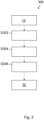
- Figure 1 shows an overall sequence of the method according to the invention for assigning electrical signals 60 in a network for electrical signals 60, in particular in a signal bus, in particular of a vehicle.
- a network for electrical signals 60, in particular in a signal bus, in particular of a vehicle.
- Several electronic components for example control units, are connected to the network.
- the network may, for example, take the form of at least one CAN bus, such as is typically used in vehicles, in particular in the drive sector.
- the method is not limited to the application to networks with CAN buses or networks in vehicles.
- the method has at least the steps described below.
- Signals and/or data from time-dependent data sources 10 of the network are preprocessed in step S100.
- Signals and/or data from time-independent data sources 30 of the network are preprocessed in step S102.
- first signals 50 are generated in the module 200 as reference signals 50. Further, second signals 60 are generated, which are unknown and cannot yet be fully assigned.
- the number of first signals 50, the reference signals 50, is denoted by R v and the number of unknown second signals 60 is denoted by U v .
- First signals 50 and second signals 60 are fed as input to block 900 for assigning the second signals 60.
- module 700 at least one of the second signals 60 is compared to at least one of the first signals 50.
- module 800 the at least one of the second signals 60 is compared to differences in the second signals 60 in data traces 12, 13 ( Figure 8 ) for the second signal 60 based on at least two known different network states 20.
- the block 900 is performed once, whereby a number U n of unassigned second signals 60 after being assigned in the block 900 is less than or equal to a number U v of unassigned second signals 60 before being assigned in the block 900, and thereby a number Zn of assigned second signals 62 after being assigned in the block 900 is greater than or equal to a number Z v of assigned second signals 62 before being assigned in the block 900.
- step S106 it is checked whether the number U n of unassigned second signals 60 is zero after assigning. If this is the case, the assignment is terminated.
- step S104 a modification is made in step S104 by known different network states 20 ( Figure 2 ) and/or output conditions of the network before further first signals 50 and second signals 60 are generated in module 200. Thereafter, the block 900 for assigning the second signals 60 is performed again.
- module 700 at least one of the further second signals 60 is compared to at least one of the further first signals 50
- module 800 the at least one of the further second signals 60 is compared to differences of the further second signals 60 in data traces 12, 13 for the second signal 60 due to at least two known different network conditions 20.
- step S106 If the number U n of unassigned second signals 60 after assigning in block 900 is zero when interrogated in step S106, then the assignment of the unknown second signals 60 is complete and the process is terminated in step S108.
- the assigning block 900 of second signals 60 can be automated, so that manual input of information can be largely eliminated. As a result, the time required to assign unknown second signals 60 in a network can be significantly reduced.
- Figure 2 shows a flowchart for generating first and second signals 50, 60 in module 200 of the method.
- Data sources 10, 30 for generating first and second signals 50, 60 may include at least one time-independent data source 30 from the group of the type: data memory 32, known database file 34 of a known network, subscriber 36 on the network, circuit diagram 38. Further, the data sources 10, 30 may comprise at least one time-dependent data source 10 from the group of the type: data trace 12, analog electrical voltage 14, diagnostic data 16, trigger input 18, network state 20.
- Diagnostic data 16 may be provided via the network or via files, such as a data trace linked to a data memory 32.
- Trigger inputs 18 may be provided via a manual input when a network condition has changed, such as when a vehicle door has been operated.
- First and second signals 50, 60 are provided as time-dependent signals 40.
- a first signal 50 may be generated in step S206 from an entry in a data memory 32 associated with a data trace 12.
- Senders of a data packet, in particular of a message can be identified in step S202 via inputs from subscribers 36 on the network as well as via data from data traces 12, for example by specifically disconnecting control units connected to the network from the network using a CAN router or the like.
- step S204 verification of potentially similar signals 50, 60 from an already known model from already known database files 34 and the new model is performed.
- First signals 50 are generated using the database file 34 and data traces 12 with similar network states, a known model and a new model. By comparing the signal traces and their origin (for example, from a control unit), a first signal 50 can be generated as a reference signal 50 if a match is found and stored in the data memory 32.
- Other first signals 50 may be generated via inputs of analog voltages 14, for example oscillograms, measured voltage levels from a measurement box, and circuit diagrams 38. In step S208, this is done by determining which one of the signals represents the voltage, for example.
- Diagnostic data 16 is decoded and processed in step S210 so as to be provided as a further first signal 50.
- Trigger inputs 18 are also used to generate first signals 50.
- Signals 50 may be generated for this purpose, in the case of a vehicle CAN bus, for example, via an ABS active signal, messages in the electronic dash board, a door OPEN/CLOSED signal.
- a network state 20 may be provided directly as a first signal 50.
- data packets in particular messages, are correlated on the basis of data traces 12.
- Data packets can in particular be formed as CAN messages in a CAN network.
- database files 34 are generated from messages from module 300 and identified senders of messages from step S202.
- second signals 60 are categorized in module 600.
- the categorized second signals 60 are stored in the data memory 32.
- Figure 3 shows a flowchart for correlating data packets in module 300 ( Figure 2 ) of the method.
- Data packets are obtained via data traces 12.
- Data packets can, in particular, take the form of CAN messages in a CAN network.
- step S302 an algorithm is first used to determine a probability 70 for a similarity of data packets present on the data trace 12.
- step S304 a routing table is then created based on the probabilities determined above.
- a buffer contains the similarity probability with each other data packet for each data packet.
- the routing table includes messages which occur at least twice in the data trace 12.
- step S306 the data packets are checked for duplicates and duplicate data packets are discarded.
- the routing table is stored in data memory 32.
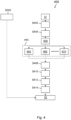
- Figure 4 shows a flowchart for generating database files in module 400 ( Figure 2 ) of the method.
- the module 400 is based on input of data packets from data traces12, in particular CAN messages on so-called CAN traces in the case of a CAN network, and can run automated with at least one algorithm 450, 460, 470 of at least one machine learning method.
- At least one of the methods of the neural network type, support vector machines, decision tree, can be advantageously used.
- the so-called "least significant bits" of each data packet are determined, for example via a bit change frequency, to find out where signals 60 start.
- step S404 second signals 60 of different lengths are generated for each existing data packet.
- features 22 are generated in the module 500 that include at least a frequency of bit changes, a histogram of second signals 60, a histogram of time derivatives of the second signals 60.
- the features 22 are stored in a buffer.
- the generated second signals 60 are evaluated according to whether the signal 60 is a signal 60 of the wanted length.
- Various machine learning methods 450, 460, 470 can be used for this purpose.
- step S408 the data is stored in a buffer.
- step S410 for each length of a signal 60, for each bit, each network state, and each machine learning method 450, 460, 470, it is determined in how many data traces 12 a signal 60 was found at that bit with that method 450, 460, 470 and that network state.
- this information is combined to a profile.
- step S414 the machine learning method 450, 460, 470 is used to evaluate which signals 60 are present in a data packet based on the profile.
- This information is stored in the data memory 32 together with the information about the signal origins determined in step S202 in Figure 2 about the identification of the senders of data packets.
- Figure 5 shows a flowchart for generating features 22 in module 500 ( Figure 4 ) of the method.
- features 22 are generated for time-dependent signals 40, which may be first and second signals 50, 60 (see Figure 2 ).
- a frequency of bit changes is generated in step S502, which indicates how often a bit of a signal 50, 60 has changed value.
- step S504 a histogram of the values of signals 60 is generated, and in step S506, a histogram of time derivatives of signals 60 is generated. In step S508, other characteristics, such as a difference of bit changes, or a status of whether the bit has ever toggled, may be added.
- the features 22 are stored in the buffer.
- Figure 6 shows a flowchart for categorizing second signals 60 in module 600 ( Figure 2 ) of the method.
- features 22 are first generated in module 500 as described in Figure 5 .
- each second signal 60 is evaluated based on the feature 22 as to which signal type it is.
- the signal type can be, for example, "physical”, “logical”, a counter “counter”, cyclic redundancy check "CRC”.
- the second signal 60 is directly classified under associated second signals 62 and stored in the data memory 32.
- the second signal 60 is stored directly in the data memory 32.
- step S606 every second signal 60 is evaluated by means of the machine learning method 450, 460, 470 on the basis of the feature 22 according to which data type it is.
- the data may be in "unsigned integer” or "signed integer” format.
- step S608 still checks whether a specific network state 20 is available.
- step S610 a physical unit inherent to the second signal 60 is determined using the machine learning method 450, 460, 470 based on data traces 12, 13 having specific states 20 and curve shapes.
- the second signals 60 are stored in the data memory 32.
- signals 60 are stored directly in data memory 32.
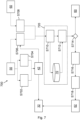
- Figure 7 shows a flowchart for comparing signals 50, 60 in module 700 of the method.
- first signals 50 are modified as reference signals on the basis of logical relationships.
- Logic diagrams, physical conditions, for example, can be used for this purpose.
- first signals 50 may be modified, for example, by undersampling, low-pass filtering, mathematical operations, bit shifts.
- First signals 50 and virtual signals 42 are selected and timed in step S706 and, together with second signals 60, which are also selected and timed in step S708, serve as input to a block 720 for determining a correlation.
- a probability of similarity between at least one of the second signals 60 and at least one of the first signals 50 and/or the virtual signal 42 is determined at step S710.
- the probability for the similarity is stored in the buffer 70.
- step S712 If there is a high probability of similarity, an identity between the first signal 50 and/or the virtual signal 42 and the second signal 60 is checked in step S712.
- step S714 If the signal 60 is assignable, which is checked in step S714, a factor and an offset are optionally determined in step S716.
- step S7108 verification is performed with a matching network state. Then, if the verification is successful, the signal 60 is stored under associated second signals 62 in the data memory 32.
- step S714 If the signal 60 is not assignable in step S714, it is further routed among unassigned signals 60.
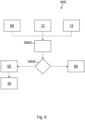
- Figure 8 shows a flowchart for evaluating differences of second signals 60 in data traces 12, 13 based on at least two known different network states 20 according to the method of the invention.
- step S804 it is then checked whether the signal 60 can be assigned. If this is the case, the signal 60 is classified under assigned signals 62 and stored in the data memory 32.
Landscapes
- Engineering & Computer Science (AREA)
- Computer Networks & Wireless Communication (AREA)
- Signal Processing (AREA)
- Small-Scale Networks (AREA)
Description
- The invention relates to a method for assigning electrical signals in a network for electrical signals, in particular in a signal bus of a vehicle, and to a computer program product for assigning electrical signals in a network for electrical signals, in particular in a signal bus of a vehicle, and to a data processing system.
- The control of drive units, for example in vehicles such as buses or trucks, is usually performed by electronic control units (ECU). These send data packets cyclically as so-called messages and thus control the operation of the engine, for example. These messages are usually sent via a controller area network (CAN bus). If, in the course of retrofitting, the powertrain is removed or replaced by another powertrain, some specific electronic control units are omitted. In order to operate without error, the vehicle's remaining ECUs need data from the removed ECUs, such as oil pressure or engine speed. If certain data is not sent, errors are reported. To prevent this, the removed ECUs can be simulated, for example. To be able to simulate the ECUs, it must be known where signals essential for operation, for example of the drive units, are located in the messages.
- Another example is the door status of a vehicle. Here, for example, the air-conditioning system must be informed whether a door is open, as the air-conditioning system must then switch to recirculation so that the doors can be properly locked again.
- Since no unified standard exists, this analysis must be performed for each vehicle model. Since the CAN bus of a vehicle can have well over a hundred different and unknown messages, a manual analysis is very time-consuming.
- General background art in the field of CAN buses is described in the publications by Verma M.E. et al.: "CAN-0: A Modular Four-Step Pipeline for Comprehensively Decoding Controller Area Network Data", ARXIV.ORG, CORNELL UNIVERSITY LIBRARY, 201 OLIN LIBRARY CORNELL UNIVERSITY ITHACA, NY 14853, 10 June 2020, XP081694669, and by Pesé M.D. et al.: "LibreCAN Automated CAN Message Translator", DESIGNING INTERACTIVE SYSTEMS CONFERENCE, ACM, 2 PENN PLAZA, SUITE 701 NEW YORKNY10121-0701 USA, 6 November 2019, pages 2283-2300, XP058637838, DOI: 10.1145/3319535.3363190, ISBN: 978-1-4503-5850-7.
- The publication by Young C. et al.: "Towards Reverse Engineering Controller Area Network Messages Using Machine Learning", 2020 IEEE 6TH WORLD FORUM ON INTERNET OF THINGS (WF-IOT), IEEE, 2 June 2020, pages 1-6, XP033840995, DOI: 10.1109/WF-IOT48130.2020.9221383, describes reverse engineering methods for analyzing CAN messages according to their functionality based on machine learning methods.
- An object of the invention is to provide an improved method for assigning electrical signals in a network for electrical signals, in particular in a signal bus of a vehicle.
- Another object is to provide a computer program product for executing such a method.
- Another object is to provide a data processing system for carrying out such a method.
- The objects are solved by the features of the independent claims. Favorable embodiments and advantages of the invention result from the further claims, the description and the drawing.
- According to one aspect of the invention, a method is proposed for assigning electrical signals in a network for electrical signals in a system, for ensuring safe functioning of the system with the network when one or more new signal sources are connected to the existing network, in particular in a signal bus of a vehicle, wherein at least the steps are performed of (i) generating first signals from data sources of the network as reference signals; (ii) generating second signals from the data sources of the network; (iii) assigning at least one of the second signals by comparing with at least one of the first signals and/or by comparing the at least one of the second signals with differences of the second signals in data traces for the second signal due to at least two known different network states;
(iv) if a number of unassigned second signals after said assigning is equal to zero, terminating said assigning of said second signals; (v) as long as said number of unassigned second signals after said assigning is greater than zero, generating further first signals and second signals having modified known different network states and/or output conditions of said network and assigning by comparing at least one of said further second signals with at least one of said further first signals and/or by comparing said at least one of said further second signals with differences of said further second signals in data traces for said second signal based on at least two known different network states, wherein for comparison with at least one of the first signals virtual signals are generated from a combination of first signals which are used for comparison with unassigned second signals. - By generating virtual signals from a combination of first signals for comparison with at least one of the first signals, which are used for comparison with unassigned second signals, the virtual signals are suitably generated from first signals, for example, on the basis of logical relationships of the network and/or by modification by means of mathematical operations, so as to be checked for similarity with second signals.
- Generating, assigning, comparing can each be done in separate modules or blocks.
- The method according to the invention allows an assignment of unknown electrical signals in a network, in particular a signal bus, especially a signal bus of a vehicle, in a very efficient way. The signal bus can be designed as a CAN bus, for example.
- CAN buses are widely used in vehicles, for example. Other signal buses or networks can also be provided for routing signals. Likewise, the method is not tied to be used in vehicles.
- Electrical signals on the network, especially in a network in a vehicle, can come from, for example, control units, signal generators, sensors, electronic components, and/or audio components. The signals link the functions of the individual components on the network to each other. Messages can transmit data packets, in particular signals, which can be addressed to specific components on the network, for example, or can be addressed to all components.
- The functions of components on the network can only run error-free if certain signals from a component are responded to in an expected manner by an addressed component. If this expected reaction fails to occur, an error is generated, for example, or certain functions in components on the network are switched off. This error-free operation is advantageously made possible by the method according to the invention.
- However, signals can also be used to exchange physical measured values or to transmit diagnostic data.
- By sending simulated messages into a CAN bus as a signal bus, it is possible, for example, to renew drive units in commercial vehicles such as buses or trucks, e.g. to replace combustion engines with alternative drives, without affecting the function of the other components connected to the bus.
- This means that components such as the electric rear axle, high-voltage battery, high-voltage auxiliary units, charging components, and the like can be integrated into a used vehicle and put into operation in a very short time.
- The assignment of unknown signals in the network allows components to be connected to an otherwise unknown network and/or provides the network with the signals necessary for smooth operation.
- For example, the assignment of unknown signals in the network enables signals from control units required in the network to be detected and control units, for example of a new powertrain, to be connected to the vehicle's network.
- This implementation enables, for example, defined and secure communication of a new electric powertrain in a used or new vehicle that was previously equipped with an internal combustion engine. The process is independent of the vehicle type (bus, commercial vehicle or passenger car, or new vehicle or used vehicle).
- However, the invention is not limited to this implementation, but also makes it possible to connect one or more new signal sources to an existing network and to ensure the safe functioning of the system with the network. For example, the method according to the invention can also be used to analyze the communication between sensors and actuators in the home automation sector or in the industrial sector, for example on a PLC bus.
- In the method according to the invention, machine learning methods are used which analyze the unknown signals. For example, the methods neural networks, support vector machines (SVMs) and/or decision trees, e.g. for evaluating the lengths of data packets, can be used for this purpose.
- The method is based on a defined procedure with which the data can be analyzed and assigned to features. Different machine learning methods are applied to the signals to decide which method is best suited for the corresponding problem.
- This eliminates the need for time-consuming, manual programming when assigning unknown signals in the network. The method is process-safe and allows fulfillment of the requirements for functional safety of vehicles according to the ISO 26262:2018 standard from 2018.
- The method advantageously offers, for example, a significant reduction in the development time of an aftermarket powertrain for a vehicle model. The invention allows the functional safety of electronics, control units, electronic systems and components to be maintained, in particular for safety-critical applications in vehicles.
- According to an advantageous embodiment of the method, at least one time-independent data source and at least one time-dependent data source may be used as the data source. Time-independent data sources may include, for example: data memory, known database file of a known network, subscriber on the network, circuit diagram. Time-dependent data sources may include, for example: data trace, analog electrical voltage, diagnostic data, trigger input, network state.
- In this way, available information can be used expediently to extract both first signals as reference signals and second signals from the data traces and to process them appropriately.
- According to an advantageous embodiment of the method, at least the steps of (i) correlating data packets, in particular messages; (ii) generating database files; (iii) categorizing the second signals; (iv) storing the categorized second signals in the data memory can be performed for generating second signals.
- These complex steps conveniently allow to generate second signals which can be identified and assigned with high probability by means of the following assignment steps. The correlation, generation as well as categorization is advantageously carried out in a respective module.
- According to an advantageous embodiment of the method, the second signals can be determined from a measurement of data traces and/or analog voltages on the network. In particular, signals on data traces provide the basis for assignment for the second signals.
- Signals due to analog voltages can additionally be used to identify second signals in order to increase the assignment probability.
- According to an advantageous embodiment of the method, for correlating data packets at least the steps can be performed of (i) determining a probability for a similarity of data packets present on a data trace; (ii) creating a routing table; (iii) discarding duplicate data packets. Data packets, which are available in particular in the form of messages on data traces, can be checked for similarity in this way. In particular, duplicate data packets can be identified and discarded in this way, so that the number of unassigned second signals can be reduced.
- According to an advantageous embodiment of the method, when generating a database file, features may be generated comprising at least a frequency of bit changes, a histogram of second signals, a histogram of time derivatives of the second signals, which features are stored in a buffer.
- According to an advantageous embodiment of the method, when generating a database file with an algorithm of at least one machine learning method, it can be evaluated whether it is a second signal of a specified length.
- Advantageously, for generating a data memory, each message can be divided into signals of different, predetermined lengths. Thus signal candidates are generated. For the signal candidates, features are generated which include at least a frequency of bit changes, a histogram of second signals, a histogram of time derivatives of the second signals.
- Based on these features, the algorithm of at least one machine learning method can be used to evaluate whether the signal is of the specified length. The evaluation is stored in the buffer.
- In addition, a profile of the second signals can be used to evaluate which second signals are present in a data packet. However, the profile can only be created once it has been determined that it is a second signal of a specified length.
- Second signals can be advantageously evaluated for a wanted length of the signal based on the features. This testing and evaluation can advantageously be done with one of the machine learning methods.
- According to an advantageous embodiment of the method, at least one of the methods of the type neural networks, support vector machines, decision tree can be used as at least one machine learning method. These methods represent very widely used machine learning methods, which can be used in a broad field and for which corresponding tools are also commercially available.
- According to an advantageous embodiment of the method, the algorithm can be trained to recognize unassigned second signals in data traces based on the first signals. The recognition can advantageously be performed by means of the machine learning algorithm.
- According to an advantageous embodiment of the method, the algorithm can be trained to generate a database file based on a profile of unassigned second signals using the first signals. Thus, an efficient generation of a database file based on a profile of unassigned second signals can be achieved.
- According to an advantageous embodiment of the method, when categorizing the second signals by means of the algorithm, each second signal can be evaluated according to which signal type it is and, depending on the signal type, a data type can be determined by means of the features and the algorithm.
- For example, "physical" or "logical" can be assigned as the signal type. For the data type, the data format "unsigned integer" or "signed integer" can be assigned, for example. In addition, a physical unit inherent in the second signal can be determined by means of the algorithm on the basis of data traces with specific network states and curve shapes.
- As the unit of the second signals, for example, in the case of a signal of the signal type "physical", the physical unit can be assigned.
- According to an advantageous embodiment of the method, the algorithm can be trained to categorize unassigned second signals based on the first signals. Thus, an efficient categorization of unassigned second signals can be achieved.
- According to an advantageous embodiment of the method, the algorithm can be trained to determine an inherent physical unit of unassigned second signals based on the first signals. Thus, an efficient determination of an inherent physical unit of unassigned second signals can be achieved.
- According to an advantageous embodiment of the method, when comparing signals by means of the algorithm, the probability of similarity between at least one of the second signals and at least one of the first signals or at least one of the virtual signals can be determined and, if the probability of similarity is high, an identity of the causative data source between the first signal or the virtual signal and the second signal can be checked. In this way, a similarity or even identity between a first signal or a virtual signal and a second signal can be detected very efficiently and thus the second signal can be assigned.
- According to an advantageous embodiment of the method, when comparing the at least one of the second signals with differences of the second signals in data traces for the second signal based on at least two known, different network states, differences of the second signals in the at least two network states can be evaluated.
- In this way, differences in signals between two network states can be effectively detected, for example, network states where signals have changed in only one data trace.
- According to an advantageous embodiment of the method, at least one data transmission link, in particular a CAN bus, can be used as the network. CAN bus architectures are widely used in vehicles and represent the most commonly used network type. Messages are known in CAN networks as CAN messages. Data traces are known as CAN traces, among other things. Data traces contain signals depending on time, for example a diagnostic extract in csv files, or videos.
- According to an advantageous embodiment of the method, the generation of a database file from second signals can be automated using the at least one machine learning algorithm.
- In this way, manual recognition of the second signals can be advantageously dispensed with, so that a significant time saving can be achieved when assigning second signals on an unknown network.
- According to another aspect of the invention, a computer program product is proposed for assigning electrical signals in a network for electrical signals in a system, for ensuring safe functioning of the system with the network when one or more new signal sources are connected to the existing network, in particular in a signal bus of a vehicle, the computer program product comprising at least one computer-readable storage medium comprising program instructions executable on a computer system and causing the computer system to perform a method as described above.
- At least the steps of (i) generating first signals from data sources of the network as reference signals; (ii) generating second signals from the data sources of the network; (iii) assigning at least one of the second signals by comparing with at least one of the first signals and/or by comparing the at least one of the second signals with differences of the second signals in data traces for the second signal due to at least two known different network conditions; (iv) if a number of unassigned second signals after assigning is equal to zero, terminating the assigning of the second signals; (v) as long as a number of unassigned second signals after said assigning is greater than zero, generating further first signals and second signals having modified known different network states and/or initial conditions of said network, and assigning by comparing at least one of said further second signals with at least one of said further first signals and/or by comparing said at least one of said further second signals with differences of said further second signals in data traces for said second signal based on at least two known different network states, wherein for comparison with at least one of the first signals virtual signals are generated from a combination of first signals which are used for comparison with unassigned second signals.
- By generating virtual signals from a combination of first signals for comparison with at least one of the first signals, which are used for comparison with unassigned second signals, the virtual signals are suitably generated from first signals, for example, on the basis of logical relationships of the network and/or by modification by means of mathematical operations, so as to be checked for similarity with second signals.
- The computer program product advantageously serves to implement the method according to the invention. To avoid unnecessary repetition, reference is made to the description of the method.
- According to another aspect of the invention, a data processing system for executing a data processing program comprising computer-readable program instructions is proposed for executing a method for assigning electrical signals in a network for electrical signals, in particular in a signal bus of a vehicle, in particular as described above.
- The data processing system is advantageously used to carry out the method according to the invention. To avoid unnecessary repetition, reference is made to the description of the method.
- Further advantages can be seen from the following description of the drawings. The figures show examples of embodiments of the invention. The figures, the description and the claims contain numerous features in combination. The skilled person will expediently also consider the features individually and combine them to form useful further combinations.
-
- Fig. 1
- an overall sequence of the method according to the invention for allocating electrical signals in a network for electrical signals, in particular in a signal bus of a vehicle;
- Fig. 2
- a flowchart for generating first and second signals according to the method of the invention;
- Fig. 3
- a flowchart for correlating data packets according to the method of the invention;
- Fig. 4
- a flowchart for generating database files according to the method of the invention;
- Fig. 5
- a flowchart for generating features according to the method of the invention;
- Fig. 6
- a flowchart for categorizing signals according to the method of the invention;
- Fig. 7
- a flowchart for comparing signals according to the method of the invention; and
- Fig. 8
- a flowchart for evaluating differences of second signals in data traces based on at least two known different network states according to the method according to the invention.
- In the figures, components of the same kind or having the same effect are numbered with the same reference signs. The figures show examples only and are not to be understood as limiting.
- Directional terminology used in the following, with terms such as "left", "right", "above", "below", "before" "behind", "after" and the like, is merely for better understanding of the figures and is in no way intended to represent a limitation of generality. The components and elements shown, their design and use may vary in accordance with the considerations of a person skilled in the art and may be adapted to the particular applications.
-
Figure 1 shows an overall sequence of the method according to the invention for assigningelectrical signals 60 in a network forelectrical signals 60, in particular in a signal bus, in particular of a vehicle. Several electronic components, for example control units, are connected to the network. The network may, for example, take the form of at least one CAN bus, such as is typically used in vehicles, in particular in the drive sector. However, it is understood that the method is not limited to the application to networks with CAN buses or networks in vehicles. - The method has at least the steps described below.
- Signals and/or data from time-
dependent data sources 10 of the network are preprocessed in step S100. Signals and/or data from time-independent data sources 30 of the network are preprocessed in step S102. - From the signals and/or data preprocessed in S100 and S102, first signals 50 are generated in the
module 200 as reference signals 50. Further, second signals 60 are generated, which are unknown and cannot yet be fully assigned. The number offirst signals 50, the reference signals 50, is denoted by Rv and the number of unknownsecond signals 60 is denoted by Uv. - First signals 50 and
second signals 60 are fed as input to block 900 for assigning the second signals 60. Inmodule 700, at least one of the second signals 60 is compared to at least one of the first signals 50. Alternatively or additionally, inmodule 800, the at least one of the second signals 60 is compared to differences in thesecond signals 60 in data traces 12, 13 (Figure 8 ) for thesecond signal 60 based on at least two known different network states 20. - The
block 900 is performed once, whereby a number Un of unassignedsecond signals 60 after being assigned in theblock 900 is less than or equal to a number Uv of unassignedsecond signals 60 before being assigned in theblock 900, and thereby a number Zn of assigned second signals 62 after being assigned in theblock 900 is greater than or equal to a number Zv of assigned second signals 62 before being assigned in theblock 900. - In step S106, it is checked whether the number Un of unassigned
second signals 60 is zero after assigning. If this is the case, the assignment is terminated. - If the number Un of unassigned
second signals 60 is greater than zero after assigning inblock 900, a modification is made in step S104 by known different network states 20 (Figure 2 ) and/or output conditions of the network before furtherfirst signals 50 andsecond signals 60 are generated inmodule 200. Thereafter, theblock 900 for assigning the second signals 60 is performed again. Inmodule 700, at least one of the furthersecond signals 60 is compared to at least one of the furtherfirst signals 50, while inmodule 800, the at least one of the furthersecond signals 60 is compared to differences of the furthersecond signals 60 in data traces 12, 13 for thesecond signal 60 due to at least two knowndifferent network conditions 20. - If the number Un of unassigned
second signals 60 after assigning inblock 900 is zero when interrogated in step S106, then the assignment of the unknownsecond signals 60 is complete and the process is terminated in step S108. - The assigning
block 900 ofsecond signals 60 can be automated, so that manual input of information can be largely eliminated. As a result, the time required to assign unknownsecond signals 60 in a network can be significantly reduced. -
Figure 2 shows a flowchart for generating first andsecond signals module 200 of the method. -
Data sources second signals data memory 32, knowndatabase file 34 of a known network,subscriber 36 on the network, circuit diagram 38. Further, the data sources 10, 30 may comprise at least one time-dependent data source 10 from the group of the type:data trace 12, analogelectrical voltage 14,diagnostic data 16, triggerinput 18,network state 20. -
Diagnostic data 16 may be provided via the network or via files, such as a data trace linked to adata memory 32.Trigger inputs 18 may be provided via a manual input when a network condition has changed, such as when a vehicle door has been operated. - First and
second signals dependent signals 40. - For example, a
first signal 50 may be generated in step S206 from an entry in adata memory 32 associated with adata trace 12. - Senders of a data packet, in particular of a message, can be identified in step S202 via inputs from
subscribers 36 on the network as well as via data from data traces 12, for example by specifically disconnecting control units connected to the network from the network using a CAN router or the like. - In step S204, verification of potentially
similar signals database file 34 and data traces 12 with similar network states, a known model and a new model. By comparing the signal traces and their origin (for example, from a control unit), afirst signal 50 can be generated as areference signal 50 if a match is found and stored in thedata memory 32. - Other
first signals 50 may be generated via inputs ofanalog voltages 14, for example oscillograms, measured voltage levels from a measurement box, and circuit diagrams 38. In step S208, this is done by determining which one of the signals represents the voltage, for example. -
Diagnostic data 16 is decoded and processed in step S210 so as to be provided as a furtherfirst signal 50. -
Trigger inputs 18 are also used to generate first signals 50.Signals 50 may be generated for this purpose, in the case of a vehicle CAN bus, for example, via an ABS active signal, messages in the electronic dash board, a door OPEN/CLOSED signal. - A
network state 20 may be provided directly as afirst signal 50. - To generate
second signals 60, at least the following steps are performed. - In
module 300, data packets, in particular messages, are correlated on the basis of data traces 12. Data packets can in particular be formed as CAN messages in a CAN network. - In
module 400, database files 34 are generated from messages frommodule 300 and identified senders of messages from step S202. - In the next step, second signals 60 are categorized in
module 600. - The categorized second signals 60 are stored in the
data memory 32. -
Figure 3 shows a flowchart for correlating data packets in module 300 (Figure 2 ) of the method. - Data packets are obtained via data traces 12. Data packets can, in particular, take the form of CAN messages in a CAN network.
- In step S302, an algorithm is first used to determine a
probability 70 for a similarity of data packets present on thedata trace 12. - In step S304, a routing table is then created based on the probabilities determined above. A buffer contains the similarity probability with each other data packet for each data packet. The routing table includes messages which occur at least twice in the
data trace 12. - Then, in step S306, the data packets are checked for duplicates and duplicate data packets are discarded.
- The routing table is stored in
data memory 32. -
Figure 4 shows a flowchart for generating database files in module 400 (Figure 2 ) of the method. - The
module 400 is based on input of data packets from data traces12, in particular CAN messages on so-called CAN traces in the case of a CAN network, and can run automated with at least onealgorithm - As a machine learning method, at least one of the methods of the neural network type, support vector machines, decision tree, can be advantageously used.
- In the first step S402 the so-called "least significant bits" of each data packet are determined, for example via a bit change frequency, to find out where signals 60 start.
- In the next step S404,
second signals 60 of different lengths are generated for each existing data packet. - Thereafter, features 22 are generated in the
module 500 that include at least a frequency of bit changes, a histogram ofsecond signals 60, a histogram of time derivatives of the second signals 60. Thefeatures 22 are stored in a buffer. - Subsequently, in
block 440, the generated second signals 60 are evaluated according to whether thesignal 60 is asignal 60 of the wanted length. Variousmachine learning methods - In step S408, the data is stored in a buffer.
- In the following step S410, for each length of a
signal 60, for each bit, each network state, and eachmachine learning method signal 60 was found at that bit with thatmethod - In the next step S412 this information is combined to a profile.
- In step S414, the
machine learning method - This information is stored in the
data memory 32 together with the information about the signal origins determined in step S202 inFigure 2 about the identification of the senders of data packets. -
Figure 5 shows a flowchart for generatingfeatures 22 in module 500 (Figure 4 ) of the method. - In
module 500, features 22 are generated for time-dependent signals 40, which may be first andsecond signals 50, 60 (seeFigure 2 ). - For this purpose, a frequency of bit changes is generated in step S502, which indicates how often a bit of a
signal - In step S504, a histogram of the values of
signals 60 is generated, and in step S506, a histogram of time derivatives ofsignals 60 is generated. In step S508, other characteristics, such as a difference of bit changes, or a status of whether the bit has ever toggled, may be added. - The
features 22 are stored in the buffer. -
Figure 6 shows a flowchart for categorizingsecond signals 60 in module 600 (Figure 2 ) of the method. - For unknown
second signals 60, features 22 are first generated inmodule 500 as described inFigure 5 . - Thereafter, in step S602, using the
machine learning method second signal 60 is evaluated based on thefeature 22 as to which signal type it is. The signal type can be, for example, "physical", "logical", a counter "counter", cyclic redundancy check "CRC". - Depending on the signal type, branching takes place in step S604.
- In the case of the "counter" or "CRC" type, the
second signal 60 is directly classified under associated second signals 62 and stored in thedata memory 32. - In the case of the "Logical" signal type, the
second signal 60 is stored directly in thedata memory 32. - In the case of the signal type "physical", in step S606 every
second signal 60 is evaluated by means of themachine learning method feature 22 according to which data type it is. For example, the data may be in "unsigned integer" or "signed integer" format. - After that, step S608 still checks whether a
specific network state 20 is available. - If so, in step S610, a physical unit inherent to the
second signal 60 is determined using themachine learning method specific states 20 and curve shapes. - Thereafter, the
second signals 60 are stored in thedata memory 32. - If no
specific network state 20 is available, signals 60 are stored directly indata memory 32. -
Figure 7 shows a flowchart for comparingsignals module 700 of the method. - In step S702, first signals 50 are modified as reference signals on the basis of logical relationships. Logic diagrams, physical conditions, for example, can be used for this purpose.
- In step S704, first signals 50 may be modified, for example, by undersampling, low-pass filtering, mathematical operations, bit shifts.
- By means of both steps S702 and S704,
virtual signals 42 are generated from thefirst signals 50, which are stored in thedata memory 32. - First signals 50 and
virtual signals 42 are selected and timed in step S706 and, together withsecond signals 60, which are also selected and timed in step S708, serve as input to ablock 720 for determining a correlation. - At
block 720, a probability of similarity between at least one of thesecond signals 60 and at least one of thefirst signals 50 and/or thevirtual signal 42 is determined at step S710. The probability for the similarity is stored in thebuffer 70. - If there is a high probability of similarity, an identity between the
first signal 50 and/or thevirtual signal 42 and thesecond signal 60 is checked in step S712. - If the
signal 60 is assignable, which is checked in step S714, a factor and an offset are optionally determined in step S716. - In step S718, verification is performed with a matching network state. Then, if the verification is successful, the
signal 60 is stored under associated second signals 62 in thedata memory 32. - If the
signal 60 is not assignable in step S714, it is further routed amongunassigned signals 60. -
Figure 8 shows a flowchart for evaluating differences ofsecond signals 60 in data traces 12, 13 based on at least two known different network states 20 according to the method of the invention. - According to the diagram shown in the Figure, when the at least one of the second signals 60 is compared in the
module 800 to differences of thesecond signals 60 in data traces 12, 13 for thesecond signal 60, differences of thesecond signals 60 in the at least two network states 20 are evaluated based on at least two known different network states 20. - For this purpose, inputs of at least a
second signal 60, as well as data traces 12, 13 from respectively different network states 20, are introduced into the evaluation step S802. The differences of thesignals 60 in both network states 20, for example states which have only changed in onedata trace - In step S804, it is then checked whether the
signal 60 can be assigned. If this is the case, thesignal 60 is classified under assignedsignals 62 and stored in thedata memory 32. - If this is not the case, the
signal 60 will continue under unassigned signals 60. -
- 10
- time-dependent data sources
- 12
- data trace
- 13
- data trace
- 14
- analog voltage
- 16
- diagnostic data
- 18
- trigger input
- 20
- network state
- 22
- feature
- 30
- time-independent data sources
- 32
- data memory
- 34
- database file
- 36
- subscriber on signal bus
- 38
- circuit diagram
- 40
- time-dependent signal
- 42
- virtual signal
- 50
- first signal
- 60
- second signal
- 62
- assigned signal
- 70
- buffer
- 200
- module generate signals
- 300
- module correlation of data packets
- 400
- module generate database file
- 440
- block evaluate signals by length
- 450
- algorithm of a machine learning method 1
- 460
- algorithm of machine learning method 2
- 470
- algorithm of machine learning method 3
- 500
- module generating feature module
- 600
- module categorize signals
- 700
- module compare signals
- 720
- block correlation
- 800
- module comparison between states
- 900
- block assign
- S100
- preprocessing
- S102
- preprocessing
- S104
- modify network state
- S106
- check if unassigned signals are present
- S108
- end
- S202
- identify sender
- S204
- verification
- S206
- generate signals
- S208
- compare with schematic
- S210
- decoding
- S212
- generate signals
- S302
- determine similarity probability
- S304
- create routing table
- S306
- discard duplicate data packets
- S402
- determine least significant bit
- S404
- generate signals of different lengths
- S408
- buffer data
- S410
- determine number of data traces for each signal
- S412
- summarize to profile
- S414
- evaluate which signals in data packet
- S502
- generate bit change frequency
- S504
- generate histogram values
- S506
- generate histogram derivatives
- S508
- other characteristics
- S602
- evaluate signal type
- S604
- check signal type
- S606
- evaluate data type
- S608
- check data type
- S610
- determine unit
- S702
- change first signals
- S704
- change first signals
- S706
- select signals
- S708
- select signals
- S710
- determine similarity probability
- S712
- check equality
- S714
- check signal assignable
- S716
- determine factor, offset
- S718
- verification
- S802
- determine differences
- S804
- check signal assignable
Claims (17)
- A method for assigning electrical signals (60) in a network for electrical signals (60) in a system, for ensuring safe functioning of the system with the network when one or more new signal sources are connected to the existing network, wherein at least the steps are performed(i) generating first signals (50) from data sources (10, 30) of the network as reference signals (50);(ii) generating second signals (60) from the data sources (10, 30) of the network;(iii) assigning at least one of the second signals (60) by comparing it to at least one of the first signals (50) and/or by comparing the at least one of the second signals (60) with differences in the second signals (60) in data traces (12, 13) for the second signal (60) based on at least two known, different network states (20);(iv) if a number (Un) of unassigned second signals (60) is equal to zero after assigning, terminating assigning of the second signals (60);(v) as long as the number (Un) of unassigned second signals (60) is greater than zero after assigninggenerating of further first signals (50) and second signals (60) with modified known different network states (20) and/or output conditions of the network and assigning by comparing at least one of the further second signals (60) with at least one of the further first signals (50) and/or by comparing the at least one of the further second signals (60) with differences of the further second signals (60) in data traces (12, 13) for the second signal (60) based on at least two known different network states (20),
wherein for comparison with at least one of the first signals (50) virtual signals (42) are generated from a combination of first signals (50) which are used for comparison with unassigned second signals (60). - The method according to claim 1, wherein at least one time-independent data source (30) selected from the group consisting of: data memory (32), known database file (34) of a known network, subscriber (36) on the network, circuit diagram (38), and
at least one time-dependent data source (10) selected from the group of the type: data trace (12), analog electrical voltage (14), diagnostic data (16), trigger input (18), network state (20) is used as data source (10, 30). - The method according to any one of the preceding claims, wherein for generating second signals (60) at least the steps are performed(i) correlating data packets, especially messages(ii) generating database files (34);(iii) categorizing the second signals (60);(iv) storing the categorized second signals (60) in a data memory (32), in particular,wherein the second signals (60) are determined from a measurement of data traces (12, 13) and/or analog voltages (14) on the network.
- The method according to claim 3, wherein for correlating data packets at least the steps are performed(i) determining a probability for a similarity of data packets present on a data trace (12);(ii) creating a routing table based on the determined probability;(iii) discarding duplicate data packets.
- The method according to any one of claims 3 to 4,
wherein, when generating a database file (34), features (22) are generated, the features (22) comprising at least a frequency of bit changes, a histogram of second signals (60), a histogram of time derivatives of the second signals (60), which features (22) are stored in a buffer. - The method of any one of claims 3 to 5,wherein, when generating a database file (34) with an algorithm (450, 460, 470) of at least one machine learning method, it is evaluated whether it is a second signal (60) of a specified length, orwherein, when generating a database file (34) with an algorithm (450, 460, 470) of at least one machine learning method, it is evaluated whether it is a second signal (60) of a specified length and, based on a profile of the second signals (60), it is evaluated which second signals (60) are present in a data packet,
in particularwherein as at least one machine learning method at least one of the methods of the type neural networks, support vector machines, decision tree, is used. - The method of claim 6, wherein the algorithm (450, 460, 470) is trained to detect unassigned second signals (60) in data traces (12, 13) based on the first signals (50).
- The method of any one of claims 6 to 7, wherein the algorithm (450, 460, 470) is trained on generating a database file (34) based on a profile of unassigned second signals (60) using the first signals (50).
- The method according to any one of claims 6 to 8, wherein, when categorizing the second signals (60) by means of the algorithm (450, 460, 470), each second signal (60) is evaluated according to which signal type it is and, depending on the signal type, a data type is determined by means of the features (22) and the algorithm (450, 460, 470), and wherein a physical unit inherent in the second signal (60) is determined by means of the algorithm (450, 460, 470) on the basis of data traces (12, 13) with specific network states (20) and curve shapes.
- The method of any one of claims 6 to 9, wherein the algorithm (450, 460, 470) is trained to categorize unassigned second signals (60) based on the first signals (50).
- The method of any one of claims 6 to 10, wherein the algorithm (450, 460, 470) is trained to determine an inherent physical unit of unassigned second signals (60) based on the first signals (50).
- The method according to any one of claims 6 to 11, wherein, when comparing signals (50, 60), the probability of similarity between at least one of the second signals (60) and at least one of the first signals (50) or at least one of the virtual signals (42) is determined and, if the probability of similarity is high, an identity of the causative data source (10, 30) between the first signal (50) or the virtual signal (42) and the second signal (60) is checked.
- The method according to any one of the preceding claims, wherein, when comparing the at least one of the second signals (60) to differences of the second signals (60) in data traces (12, 13) for the second signal (60) based on at least two known different network states (20), differences of the second signals (60) in the at least two network states (20) are evaluated.
- The method according to any one of the preceding claims, wherein at least one data transmission link, in particular a CAN bus, is used as the network.
- The method of any one of claims 6 to 14, wherein generating a database file (34) from second signals (60) using the algorithm (450, 460, 470) is automated.
- A computer program product for assigning electrical signals (60) in a network for electrical signals (60) in a system, for ensuring safe functioning of the system with the network when one or more new signal sources are connected to the existing network, the computer program product comprising at least one computer-readable storage medium comprising program instructions executable on a computer system and causing the computer system to execute a method according to at least one of the preceding claims, wherein at least the steps are performed of(i) generating first signals (50) from data sources (10, 30) of the network as reference signals (50);(ii) generating second signals (60) from the data sources (10, 30) of the network;(iii) assigning at least one of the second signals (60) by comparing it to at least one of the first signals (50) and/or by comparing the at least one of the second signals (60) to differences in the second signals (60) in data traces (12, 13) for the second signal (60) based on at least two known, different network states (20);(iv) if a number (Un) of unassigned second signals (60) is equal to zero after assigning, terminating assigning the second signals (60);(v) as long as the number (Un) of unassigned second signals (60) is greater than zero after assigning,generating further first signals (50) and second signals (60) with modified known different network states (20) and/or output conditions of the network and assigning by comparing at least one of the further second signals (60) with at least one of the further first signals (50) and/or by comparing the at least one of the further second signals (60) with differences of the further second signals (60) in data traces (12, 13) for the second signal (60) based on at least two known different network states (20),
wherein for comparison with at least one of the first signals (50) virtual signals (42) are generated from a combination of first signals (50) which are used for comparison with unassigned second signals (60). - A data processing system for executing a data processing program comprising computer-readable program instructions for executing a method for assigning electrical signals (60) in a network for electrical signals (60), in particular in a signal bus of a vehicle according to at least one of claims 1 to 15.
Applications Claiming Priority (2)
| Application Number | Priority Date | Filing Date | Title |
|---|---|---|---|
| DE102021100656.2A DE102021100656A1 (en) | 2021-01-14 | 2021-01-14 | METHOD OF ASSIGNING ELECTRICAL SIGNALS IN A NETWORK |
| PCT/EP2021/087579 WO2022152547A1 (en) | 2021-01-14 | 2021-12-23 | Method for assigning electrical signals in a network |
Publications (3)
| Publication Number | Publication Date |
|---|---|
| EP4278570A1 EP4278570A1 (en) | 2023-11-22 |
| EP4278570C0 EP4278570C0 (en) | 2024-12-04 |
| EP4278570B1 true EP4278570B1 (en) | 2024-12-04 |
Family
ID=79830807
Family Applications (1)
| Application Number | Title | Priority Date | Filing Date |
|---|---|---|---|
| EP21847491.4A Active EP4278570B1 (en) | 2021-01-14 | 2021-12-23 | Method for assigning electrical signals in a network |
Country Status (5)
| Country | Link |
|---|---|
| US (1) | US12542689B2 (en) |
| EP (1) | EP4278570B1 (en) |
| DE (1) | DE102021100656A1 (en) |
| PL (1) | PL4278570T3 (en) |
| WO (1) | WO2022152547A1 (en) |
Family Cites Families (5)
| Publication number | Priority date | Publication date | Assignee | Title |
|---|---|---|---|---|
| DE19643410B4 (en) | 1996-10-21 | 2005-08-25 | Robert Bosch Gmbh | A method of decoding a digital signal and using it in a bus system |
| JP2013123132A (en) * | 2011-12-09 | 2013-06-20 | Toyota Motor Corp | Communication device, communication system, and communication method |
| DE102014211851A1 (en) | 2014-06-20 | 2015-12-24 | Robert Bosch Gmbh | Method and device for outputting an audible warning signal of a rail vehicle and warning system for a rail vehicle |
| US11251989B2 (en) * | 2019-03-20 | 2022-02-15 | Nxp B.V. | Secure bridging of controller area network buses |
| US20240364784A1 (en) * | 2023-04-26 | 2024-10-31 | Robert Bosch Gmbh | Method and system to measure service usage and bill for associated used services based on a intrusion detection system |
-
2021
- 2021-01-14 DE DE102021100656.2A patent/DE102021100656A1/en active Pending
- 2021-12-23 WO PCT/EP2021/087579 patent/WO2022152547A1/en not_active Ceased
- 2021-12-23 EP EP21847491.4A patent/EP4278570B1/en active Active
- 2021-12-23 US US18/271,137 patent/US12542689B2/en active Active
- 2021-12-23 PL PL21847491.4T patent/PL4278570T3/en unknown
Also Published As
| Publication number | Publication date |
|---|---|
| PL4278570T3 (en) | 2025-06-09 |
| CN116868544A (en) | 2023-10-10 |
| WO2022152547A1 (en) | 2022-07-21 |
| DE102021100656A1 (en) | 2022-07-14 |
| EP4278570A1 (en) | 2023-11-22 |
| EP4278570C0 (en) | 2024-12-04 |
| US12542689B2 (en) | 2026-02-03 |
| US20230403172A1 (en) | 2023-12-14 |
Similar Documents
| Publication | Publication Date | Title |
|---|---|---|
| CN109074519B (en) | Information processing apparatus, information processing method, and program | |
| US11997119B2 (en) | Vehicle log transmission device, vehicle log analysis server, vehicle log analysis system, and vehicle log transmission/reception method | |
| Verma et al. | CAN-D: A modular four-step pipeline for comprehensively decoding controller area network data | |
| US12021886B2 (en) | Vehicle log transmission device, vehicle log analysis system, and vehicle log transmission/reception method | |
| Schmittner et al. | FMVEA for safety and security analysis of intelligent and cooperative vehicles | |
| Ezeobi et al. | Reverse engineering controller area network messages using unsupervised machine learning | |
| US20250039015A1 (en) | Zonal control architecture for software-defined vehicle | |
| US11302122B2 (en) | Apparatus and method for predicting injury level | |
| US20150243110A1 (en) | Method and apparatus for checking vehicle specification | |
| US12542689B2 (en) | Method for assigning electrical signals in a network | |
| WO2014077330A1 (en) | Method for determining discarded electric wire and program | |
| CN116868544B (en) | Method for distributing electrical signals in a network | |
| CN113515307A (en) | Calibratable can information processing system and method based on hybrid electric vehicle | |
| CN112765217A (en) | Data processing method and system based on edge calculation and path analysis | |
| Roque et al. | CAN-Modes: In-vehicle datasets generation and analysis in different driving situations | |
| CN110011888B (en) | A modular CAN network load rate optimization method and device | |
| CN120615189A (en) | A method for adjusting test cases for security checks | |
| CN117111584A (en) | A remote diagnosis method, device, equipment and storage medium | |
| WO2022037955A1 (en) | Method for determining an indicator of a technical system, determination unit and construction system | |
| US11079438B2 (en) | Circuitry for monitoring battery systems | |
| CN115730395A (en) | Automobile interface model generation method and device, computer equipment and storage medium | |
| Rishvanth et al. | Design of an in-vehicle network (Using LIN, CAN and FlexRay), gateway and its diagnostics using vector CANoe | |
| KR101040194B1 (en) | Apparatus and method for developing hardware topologies using verification-based process techniques in vehicle ECC systems | |
| CN116800651B (en) | An automotive bus testing system, method, electronic device, and storage medium. | |
| Wang et al. | Machine Learning with Real-time and Small Footprint Anomaly Detection System for In-Vehicle Gateway |
Legal Events
| Date | Code | Title | Description |
|---|---|---|---|
| STAA | Information on the status of an ep patent application or granted ep patent |
Free format text: STATUS: UNKNOWN |
|
| STAA | Information on the status of an ep patent application or granted ep patent |
Free format text: STATUS: THE INTERNATIONAL PUBLICATION HAS BEEN MADE |
|
| PUAI | Public reference made under article 153(3) epc to a published international application that has entered the european phase |
Free format text: ORIGINAL CODE: 0009012 |
|
| STAA | Information on the status of an ep patent application or granted ep patent |
Free format text: STATUS: REQUEST FOR EXAMINATION WAS MADE |
|
| 17P | Request for examination filed |
Effective date: 20230814 |
|
| AK | Designated contracting states |
Kind code of ref document: A1 Designated state(s): AL AT BE BG CH CY CZ DE DK EE ES FI FR GB GR HR HU IE IS IT LI LT LU LV MC MK MT NL NO PL PT RO RS SE SI SK SM TR |
|
| DAV | Request for validation of the european patent (deleted) | ||
| DAX | Request for extension of the european patent (deleted) | ||
| GRAP | Despatch of communication of intention to grant a patent |
Free format text: ORIGINAL CODE: EPIDOSNIGR1 |
|
| STAA | Information on the status of an ep patent application or granted ep patent |
Free format text: STATUS: GRANT OF PATENT IS INTENDED |
|
| INTG | Intention to grant announced |
Effective date: 20240705 |
|
| RAP1 | Party data changed (applicant data changed or rights of an application transferred) |
Owner name: MEDLABIX GMBH |
|
| GRAS | Grant fee paid |
Free format text: ORIGINAL CODE: EPIDOSNIGR3 |
|
| GRAA | (expected) grant |
Free format text: ORIGINAL CODE: 0009210 |
|
| STAA | Information on the status of an ep patent application or granted ep patent |
Free format text: STATUS: THE PATENT HAS BEEN GRANTED |
|
| AK | Designated contracting states |
Kind code of ref document: B1 Designated state(s): AL AT BE BG CH CY CZ DE DK EE ES FI FR GB GR HR HU IE IS IT LI LT LU LV MC MK MT NL NO PL PT RO RS SE SI SK SM TR |
|
| REG | Reference to a national code |
Ref country code: CH Ref legal event code: EP |
|
| REG | Reference to a national code |
Ref country code: DE Ref legal event code: R096 Ref document number: 602021023049 Country of ref document: DE |
|
| REG | Reference to a national code |
Ref country code: IE Ref legal event code: FG4D |
|
| U01 | Request for unitary effect filed |
Effective date: 20241204 |
|
| U07 | Unitary effect registered |
Designated state(s): AT BE BG DE DK EE FI FR IT LT LU LV MT NL PT RO SE SI Effective date: 20241213 |
|
| U20 | Renewal fee for the european patent with unitary effect paid |
Year of fee payment: 4 Effective date: 20250121 |
|
| PG25 | Lapsed in a contracting state [announced via postgrant information from national office to epo] |
Ref country code: HR Free format text: LAPSE BECAUSE OF FAILURE TO SUBMIT A TRANSLATION OF THE DESCRIPTION OR TO PAY THE FEE WITHIN THE PRESCRIBED TIME-LIMIT Effective date: 20241204 |
|
| PG25 | Lapsed in a contracting state [announced via postgrant information from national office to epo] |
Ref country code: ES Free format text: LAPSE BECAUSE OF FAILURE TO SUBMIT A TRANSLATION OF THE DESCRIPTION OR TO PAY THE FEE WITHIN THE PRESCRIBED TIME-LIMIT Effective date: 20241204 |
|
| PG25 | Lapsed in a contracting state [announced via postgrant information from national office to epo] |
Ref country code: NO Free format text: LAPSE BECAUSE OF FAILURE TO SUBMIT A TRANSLATION OF THE DESCRIPTION OR TO PAY THE FEE WITHIN THE PRESCRIBED TIME-LIMIT Effective date: 20250304 |
|
| PG25 | Lapsed in a contracting state [announced via postgrant information from national office to epo] |
Ref country code: GR Free format text: LAPSE BECAUSE OF FAILURE TO SUBMIT A TRANSLATION OF THE DESCRIPTION OR TO PAY THE FEE WITHIN THE PRESCRIBED TIME-LIMIT Effective date: 20250305 |
|
| PG25 | Lapsed in a contracting state [announced via postgrant information from national office to epo] |
Ref country code: RS Free format text: LAPSE BECAUSE OF FAILURE TO SUBMIT A TRANSLATION OF THE DESCRIPTION OR TO PAY THE FEE WITHIN THE PRESCRIBED TIME-LIMIT Effective date: 20250304 |
|
| PG25 | Lapsed in a contracting state [announced via postgrant information from national office to epo] |
Ref country code: SM Free format text: LAPSE BECAUSE OF FAILURE TO SUBMIT A TRANSLATION OF THE DESCRIPTION OR TO PAY THE FEE WITHIN THE PRESCRIBED TIME-LIMIT Effective date: 20241204 |
|
| PGFP | Annual fee paid to national office [announced via postgrant information from national office to epo] |
Ref country code: PL Payment date: 20250304 Year of fee payment: 4 |
|
| PG25 | Lapsed in a contracting state [announced via postgrant information from national office to epo] |
Ref country code: IS Free format text: LAPSE BECAUSE OF FAILURE TO SUBMIT A TRANSLATION OF THE DESCRIPTION OR TO PAY THE FEE WITHIN THE PRESCRIBED TIME-LIMIT Effective date: 20250404 |
|
| PG25 | Lapsed in a contracting state [announced via postgrant information from national office to epo] |
Ref country code: SK Free format text: LAPSE BECAUSE OF FAILURE TO SUBMIT A TRANSLATION OF THE DESCRIPTION OR TO PAY THE FEE WITHIN THE PRESCRIBED TIME-LIMIT Effective date: 20241204 |
|
| PG25 | Lapsed in a contracting state [announced via postgrant information from national office to epo] |
Ref country code: CZ Free format text: LAPSE BECAUSE OF FAILURE TO SUBMIT A TRANSLATION OF THE DESCRIPTION OR TO PAY THE FEE WITHIN THE PRESCRIBED TIME-LIMIT Effective date: 20241204 |
|
| REG | Reference to a national code |
Ref country code: CH Ref legal event code: PL |
|
| PG25 | Lapsed in a contracting state [announced via postgrant information from national office to epo] |
Ref country code: MC Free format text: LAPSE BECAUSE OF FAILURE TO SUBMIT A TRANSLATION OF THE DESCRIPTION OR TO PAY THE FEE WITHIN THE PRESCRIBED TIME-LIMIT Effective date: 20241204 |
|
| PLBE | No opposition filed within time limit |
Free format text: ORIGINAL CODE: 0009261 |
|
| STAA | Information on the status of an ep patent application or granted ep patent |
Free format text: STATUS: NO OPPOSITION FILED WITHIN TIME LIMIT |
|
| PG25 | Lapsed in a contracting state [announced via postgrant information from national office to epo] |
Ref country code: CH Free format text: LAPSE BECAUSE OF NON-PAYMENT OF DUE FEES Effective date: 20241231 |
|
| PG25 | Lapsed in a contracting state [announced via postgrant information from national office to epo] |
Ref country code: IE Free format text: LAPSE BECAUSE OF NON-PAYMENT OF DUE FEES Effective date: 20241223 |
|
| 26N | No opposition filed |
Effective date: 20250905 |
|
| PG25 | Lapsed in a contracting state [announced via postgrant information from national office to epo] |
Ref country code: CY Free format text: LAPSE BECAUSE OF FAILURE TO SUBMIT A TRANSLATION OF THE DESCRIPTION OR TO PAY THE FEE WITHIN THE PRESCRIBED TIME-LIMIT Effective date: 20241204 |
|
| U21 | Renewal fee for the european patent with unitary effect paid with additional fee |
Year of fee payment: 5 Effective date: 20260409 |