EP4277697B1 - Multimodale stimulationssteuerung auf basis von caps - Google Patents
Multimodale stimulationssteuerung auf basis von caps Download PDFInfo
- Publication number
- EP4277697B1 EP4277697B1 EP22703747.0A EP22703747A EP4277697B1 EP 4277697 B1 EP4277697 B1 EP 4277697B1 EP 22703747 A EP22703747 A EP 22703747A EP 4277697 B1 EP4277697 B1 EP 4277697B1
- Authority
- EP
- European Patent Office
- Prior art keywords
- pulses
- stimulation
- train
- ecap
- pulse
- Prior art date
- Legal status (The legal status is an assumption and is not a legal conclusion. Google has not performed a legal analysis and makes no representation as to the accuracy of the status listed.)
- Active
Links
Images





Classifications
-
- A—HUMAN NECESSITIES
- A61—MEDICAL OR VETERINARY SCIENCE; HYGIENE
- A61N—ELECTROTHERAPY; MAGNETOTHERAPY; RADIATION THERAPY; ULTRASOUND THERAPY
- A61N1/00—Electrotherapy; Circuits therefor
- A61N1/18—Applying electric currents by contact electrodes
- A61N1/32—Applying electric currents by contact electrodes alternating or intermittent currents
- A61N1/36—Applying electric currents by contact electrodes alternating or intermittent currents for stimulation
- A61N1/3605—Implantable neurostimulators for stimulating central or peripheral nerve system
- A61N1/36128—Control systems
- A61N1/36135—Control systems using physiological parameters
- A61N1/36139—Control systems using physiological parameters with automatic adjustment
-
- A—HUMAN NECESSITIES
- A61—MEDICAL OR VETERINARY SCIENCE; HYGIENE
- A61N—ELECTROTHERAPY; MAGNETOTHERAPY; RADIATION THERAPY; ULTRASOUND THERAPY
- A61N1/00—Electrotherapy; Circuits therefor
- A61N1/18—Applying electric currents by contact electrodes
- A61N1/32—Applying electric currents by contact electrodes alternating or intermittent currents
- A61N1/36—Applying electric currents by contact electrodes alternating or intermittent currents for stimulation
- A61N1/3605—Implantable neurostimulators for stimulating central or peripheral nerve system
- A61N1/36128—Control systems
- A61N1/36146—Control systems specified by the stimulation parameters
- A61N1/36167—Timing, e.g. stimulation onset
- A61N1/36171—Frequency
-
- A—HUMAN NECESSITIES
- A61—MEDICAL OR VETERINARY SCIENCE; HYGIENE
- A61N—ELECTROTHERAPY; MAGNETOTHERAPY; RADIATION THERAPY; ULTRASOUND THERAPY
- A61N1/00—Electrotherapy; Circuits therefor
- A61N1/18—Applying electric currents by contact electrodes
- A61N1/32—Applying electric currents by contact electrodes alternating or intermittent currents
- A61N1/36—Applying electric currents by contact electrodes alternating or intermittent currents for stimulation
- A61N1/3605—Implantable neurostimulators for stimulating central or peripheral nerve system
- A61N1/36128—Control systems
- A61N1/36146—Control systems specified by the stimulation parameters
- A61N1/36167—Timing, e.g. stimulation onset
- A61N1/36178—Burst or pulse train parameters
Definitions
- This disclosure generally relates to electrical stimulation, and more specifically, control of electrical stimulation.
- Medical devices may be external or implanted and may be used to deliver electrical stimulation to patients via various tissue sites to treat a variety of symptoms or conditions such as chronic pain, tremor, Parkinson's disease, epilepsy, urinary or fecal incontinence, sexual dysfunction, obesity, or gastroparesis.
- a medical device may deliver electrical stimulation therapy via one or more leads that include electrodes located proximate to target locations associated with the brain, the spinal cord, pelvic nerves, peripheral nerves, or the gastrointestinal tract of a patient.
- Stimulation proximate the spinal cord, proximate the sacral nerve, within the brain, and proximate peripheral nerves are often referred to as spinal cord stimulation (SCS), sacral neuromodulation (SNM), deep brain stimulation (DBS), and peripheral nerve stimulation (PNS), respectively.
- Electrical stimulation may be delivered by the medical device as a train of pulses, and the values of the parameters defining the pulses may be altered.
- Documents WO 2019/246582 A1 and WO 2019/246579 A1 relate to electrical stimulation devices.
- a stimulation system may deliver different pulse trains defined by one or more different parameter values and/or delivered via different electrode combinations.
- one pulse train may be referred to as a prime pulse train and a second pulse train may be referred to as a base pulse train, where the prime pulse train and the base pulse train work together to provide multimodal stimulation therapy to the patient.
- these different pulse trains may deliver different stimulation pulses to the patient and to different tissues, the different pulse trains may be linked in how they are perceived by the patient or how they combine to provide a perceived effect for the patient.
- the patient may benefit from the system automatically adjusting the value of one or more stimulation parameters that define the prime pulse train and/or the base pulse train that are a part of the multimodal stimulation therapy.
- the system may sense an ECAP signal elicited by a pulse of the base pulse train, as the base pulse train may be delivered at a pulse frequency conducive to sensing the elicited ECAP signal.
- the system may then determine a characteristic value of the ECAP signal and adjust one or more parameters that define subsequent pulses of the prime pulse train and, in some examples, subsequent pulses of the base pulse train. For example, the system may adjust an amplitude of the prime pulse train pulses, an electrode combination used to deliver the subsequent prime pulse train, or any other parameters associated with the prime pulse train, the base pulse train, and/or any other aspect of the multimodal stimulation therapy.
- the system may automatically adjust the values of the different pulse trains based on evoked compound action potential (ECAP) signals sensed from a patient.
- ECAP evoked compound action potential
- the distance between implanted electrodes and target nerves changes. For example, electrodes implanted along the spinal column are closer to the spinal cord when a subject lies in a supine posture state as compared to a standing posture state.
- the implanted electrodes may move closer to the spinal cord when a subject coughs or sneezes. This changing distance between the electrodes and target tissue affects neural recruitment for a given intensity of delivered stimulation and can cause the patient's perception and/or therapeutic benefit to also change.
- a characteristic value of the ECAP signal can represent the change in distance
- a system can modulate electrical stimulation, such as adjusting a parameter of the prime pulse train and/or the base pulse train of the multimodal stimulation, using the characteristic value as feedback.
- the system can increase or decrease a parameter of the pulse trains, such as amplitude, in order to maintain a target ECAP value or keep pulse train amplitudes below a threshold ECAP value, as some examples.
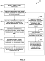
- a system includes processing circuitry configured to control delivery of a first train of electrical stimulation pulses at a first frequency to a first target tissue; control delivery of a second train of electrical stimulation pulses at a second frequency to a second target tissue different from the first target tissue, wherein at least some electrical stimulation pulses of the first train of electrical stimulation pulses are interleaved with at least some electrical stimulation pulses of the second train of electrical stimulation pulses, and wherein the first frequency is greater than the second frequency; receive an evoked compound action potential (ECAP) signal elicited by a pulse of the second train of electrical stimulation pulses; adjust, based on the ECAP signal, a first value of a parameter that at least partially defines the first train of electrical stimulation pulses to a second value; and responsive to adjusting the first value of the parameter to the second value, control delivery of subsequent pulses of the first train of electrical stimulation pulses according to the second value of the parameter.
- ECAP evoked compound action potential
- a method includes controlling, by processing circuitry, delivery of a first train of electrical stimulation pulses at a first frequency to a first target tissue; controlling, by the processing circuitry, delivery of a second train of electrical stimulation pulses at a second frequency to a second target tissue different from the first target tissue, wherein at least some electrical stimulation pulses of the first train of electrical stimulation pulses are interleaved with at least some electrical stimulation pulses of the second train of electrical stimulation pulses, and wherein the first frequency is greater than the second frequency; receiving, by the processing circuitry, an evoked compound action potential (ECAP) signal elicited by a pulse of the second train of electrical stimulation pulses; adjusting, by the processing circuitry and based on the ECAP signal, a first value of a parameter that at least partially defines the first train of electrical stimulation pulses to a second value; and responsive to adjusting the first value of the parameter to the second value, controlling, by the processing circuitry, delivery of subsequent pulses of the first train of electrical stimulation pulses according to the second
- a computer-readable storage medium including instructions that, when executed by processing circuitry, cause the processing circuitry to control delivery of a first train of electrical stimulation pulses at a first frequency to a first target tissue; control delivery of a second train of electrical stimulation pulses at a second frequency to a second target tissue different from the first target tissue, wherein at least some electrical stimulation pulses of the first train of electrical stimulation pulses are interleaved with at least some electrical stimulation pulses of the second train of electrical stimulation pulses, and wherein the first frequency is greater than the second frequency; receive an evoked compound action potential (ECAP) signal elicited by a pulse of the second train of electrical stimulation pulses; adjust, based on the ECAP signal, a first value of a parameter that at least partially defines the first train of electrical stimulation pulses to a second value; and responsive to adjusting the first value of the parameter to the second value, control delivery of subsequent pulses of the first train of electrical stimulation pulses according to the second value of the parameter.
- ECAP evoked compound action potential
- the disclosure describes examples of medical devices, systems, and techniques for adjusting electrical stimulation based on ECAP signals.
- Electrical stimulation therapy is typically delivered to a target tissue (e.g., nerves of the spinal cord or muscle) of a patient via two or more electrodes.
- Parameters of the electrical stimulation therapy e.g., electrode combination, voltage or current amplitude, pulse width, pulse frequency, etc.
- a medical device can provide therapy to a patient (e.g., pain relief therapy) by using multimodal stimulation (e.g., differential targeted multiplexed stimulation).
- multimodal stimulation e.g., differential targeted multiplexed stimulation
- Multiple modal stimulation includes different pulse trains (e.g., a prime pulse train and a base pulse train) defined by different stimulation parameters such as different frequencies and different electrode combinations. Since different types of cells, such as glial cells and neurons, respond differently to electrical fields, it is then possible to differentially modulate the response of these cell populations with distinctly different electrical parameters.
- the prime pulse train can be delivered to affect glial cells and the base pulse train can be delivered to affect neurons.
- the prime pulse train is delivered at a higher pulse frequency than the base pulse train, as described herein.
- neural recruitment at the nerves is a function of stimulation intensity (e.g., amplitude and/or pulse frequency) and distance between the target tissue and the electrodes
- stimulation intensity e.g., amplitude and/or pulse frequency
- distance between the target tissue and the electrodes movement of the electrode closer to the target tissue may result in increased neural recruitment (e.g., possible painful sensations or adverse motor function), and movement of the electrode further from the target tissue may result in decreased efficacy of the therapy for the patient.
- Certain patient postures (which may or may not include patient activity) may be representative of respective distances (or changes in distance) between electrodes and nerves and thus be an informative feedback variable for modulating stimulation therapy.
- a patient may experience discomfort or pain caused by transient patient conditions, which is referred to herein as transient overstimulation.
- the electrodes can move closer to the target tissue for a number of reasons including coughing, sneezing, laughing, valsalva maneuvers, leg lifting, cervical motions, deep breathing, or another transient patient movement. If a system is delivering stimulation during these movements, the patient may perceive the stimulation as stronger (and possibly uncomfortable) due to the decreased distance between electrodes and target tissue in a short amount of time. Although a patient may anticipate such movements and preemptively reduce stimulation intensity in an attempt to avoid these uncomfortable sensations, these patient actions interfere with normal activities and may not be sufficient to avoid uncomfortable stimulation at all times.
- ECAPs are a measure of neural recruitment because each ECAP signal represents the superposition of electrical potentials generated from a population of axons firing in response to an electrical stimulus (e.g., a stimulation pulse). Changes in a characteristic (e.g., an amplitude of a portion of the signal or area under the curve of the signal) of an ECAP signals occur as a function of how many axons have been activated by the delivered stimulation pulse. For a given set of parameter values that define the stimulation pulse and a given distance between the electrodes and target nerve, the detected ECAP signal may have a certain characteristic value (e.g., amplitude, or area under a curve).
- a characteristic value e.g., amplitude, or area under a curve
- a system can determine that the distance between electrodes and nerves has increased or decreased in response to determining that the measured ECAP characteristic value has increased or decreased. For example, if the set of parameter values stays the same and the ECAP characteristic value of amplitude increases, the system can determine that the distance between electrodes and the nerve has decreased.
- effective stimulation therapy such as multimodal therapy
- This effective stimulation therapy may provide relief from one or more conditions (e.g., patient perceived pain) without an unacceptable level of side effects (e.g., overwhelming perception of stimulation).
- side effects e.g., overwhelming perception of stimulation
- the patient changes posture or otherwise engages in physical activity the distance between the electrodes and the nerve changes as well. This change in distance can cause loss of effective therapy and/or side effects if the parameter values that define stimulation are not adjusted to compensate for the change in distance.
- the different distance between electrodes and the target nerve may also result in different sensitivities to stimulation intensity (e.g., smaller distances may result in greater sensitivities to changes in stimulation intensity).
- adjustments to stimulation parameter values may not be sufficient to maintain effective therapy or may provide stimulation that is too strong at that posture state. Therefore, it may be beneficial to maintain effective therapy by the system adjusting how stimulation intensity is changed within a given posture state and/or changing target ECAP characteristic values when a posture state of the patient has changed.
- a user adjusts a parameter value of one pulse train of therapy, the user may also need to adjust a parameter value of a second pulse train.
- the user may not even have access to adjusting amplitude of the control pulses, for example, It may be difficult for a system to employ ECAP sensing into higher frequency pulse trains or other stimulation paradigms that incorporate different areas of stimulation.
- systems, devices, and techniques provide solutions to one or more of the above-referenced problems by adjusting one or more parameters that define multimodal stimulation based on sensed ECAP signals elicited from respective pulses of one pulse train of the multimodal stimulation.
- Pulses that elicit detectable ECAP signals are described as control pulses, and pulses that can be adjusted (e.g., adjusting a value of one or more parameters that at least partially define these pulses) are referred to as informed pulses because they are informed by the ECAP elicited by the control pulses.
- informed pulse may elicit an ECAP, the system does not sense or use the ECAP elicited by an informed pulse to adjust any aspect of the stimulation.
- the base pulse train may be delivered at a lower frequency than the prime pulse train such that the system can sense an ECAP elicited from a pulse of the base pulse train.
- the base pulse train may be referred to a type of control pulses and the prime pulse train (or multiple prime pulse trains) may be referred to as a type of informed pulses herein.
- Electrical stimulation may be generally delivered to a patient by the medical device in a train of stimulation pulses, and parameters that define the stimulation pulses may include pulse amplitude (current and/or voltage), pulse frequency, pulse width, pulse shape, and/or electrode combination.
- the system may alter, adjust, change, or otherwise modulate one or more parameters of the stimulation pulses over time in order to maintain a desired level of stimulation efficacy for the patient.
- the system may adjust or modulate the value of a stimulation parameter that at least partially defines subsequent pulses of the prime pulse train, such as an amplitude, an electrode combination, a duty cycle, an interpulse interval, etc.
- the system may also adjust as aspect of the closed loop stimulation based on the ECAP characteristic value, such as a gain value that affects the response of the system to changes in the ECAP characteristic value.
- the system may determine the ECAP characteristic value from one or more aspects of the ECAP signal representative of changes in stimulation.
- sensing the ECAP at a far distance from the stimulating electrodes may avoid the artifact caused by a stimulation pulse with a long pulse width, but the ECAP signal may lose fidelity needed to detect changes to the ECAP signal that occur when the electrode to target tissue distance changes.
- the system may not be able to identify, at any distance from the stimulation electrodes, ECAPs elicited by certain stimulation pulses having relatively long pulse widths that interfere with detection of ECAP signals (e.g., stimulation pulses that may be configured to provide a therapeutic effect for the patient).
- a medical device may be configured to deliver a plurality of control pulses (e.g., at least some pulses of the base pulse train) and a plurality of informed pulses (e.g., at least one pulses of the prime pulse train(s)) in some examples.
- Informed pulses may be configured to contribute to a therapeutic effect for the patient, but the informed pulses may have a stimulation parameter, such as a pulse width or high pulse frequency, that causes at least a portion of the pulse to overlaps with the ECAP signal and prevents the system from detecting the ECAP signal or otherwise using the ECAP signal for direct feedback for modulating parameter values of the informed pulses.
- the plurality of control pulses may be configured to elicit detectable ECAP signals, and in the case of a base pulse train, configured to contribute to effective stimulation therapy along with the informed pulses.
- the control pulses may have a pulse width that is short enough, and a pulse frequency low enough, to avoid interfering with the ECAP signal detection.
- the control pulses may or may not contribute to a therapeutic effect for the patient.
- the system may be configured to adjust one or more parameters that define the informed pulses (e.g., the prime pulse train(s)) based on the detectable ECAP signals elicited by one or more control pulses (e.g., the base pulse train(s)).
- a medical device can deliver a plurality of informed pulses to provide a therapy to the patient and a plurality of control pulses.
- the control pulses may be interleaved with the delivery of the informed pulses, as is the case with the prime pulse train(s) and base pulse train(s) of multimodal stimulation.
- the medical device may alternate the delivery of informed pulses with control pulses such that a control pulse is delivered, and an ECAP signal is sensed, between consecutive informed pulses.
- one or more informed pulses may partially or completely overlap in time such that an ECAP signal elicited by a control pulse is unaffected by the delivery of an informed pulse over at least some of the same time.
- multiple control pulses are delivered, and respective ECAP signals sensed, between the delivery of consecutive informed pulses.
- multiple informed pulses will be delivered between consecutive control pulses.
- the informed pulses may be delivered according to a predetermined pulse frequency selected so that the informed pulses can produce a therapeutic result for the patient.
- One or more control pulses are then delivered, and the respective ECAP signals sensed, within one or more time windows between consecutive informed pulses delivered according to the predetermined pulse frequency.
- a medical device can administer informed pulses from the medical device uninterrupted while ECAPs are sensed from control pulses delivered during times at which the informed pulses are not being delivered.
- ECAPs are sensed by the medical device in response to the informed pulses delivered by the medical device, and control pulses are not used to elicit ECAPs.
- the system may monitor one or more characteristic values that represent detected ECAP signals and adjust a stimulation parameter value in an attempt to achieve a target ECAP characteristic value or avoid a threshold ECAP value.
- the system may adjust an informed parameter that at least partially defines subsequent informed pulses and may adjust a control parameter that at least partially defines subsequent control pulses.
- the system may employ a gain value that represents the magnitude, or rate, of change applied to a stimulation parameter in order to achieve the target ECAP characteristic value.
- the gain value may be the same or different for informed pulses and control pulses.
- the system may apply a scaling factor or otherwise adjust the gain value so that it is appropriate for informed pulses and control pulses that may have different amplitudes or other parameters. For example, if the control pulse has a higher amplitude value than the informed pulse, the system may effectively reduce the gain value, or reduce the effect of the gain value, on the change to the informed pulse amplitude because the lower amplitude value of the informed pulse may not need to be changes as much as the control pulse amplitude. The system can thus increase or decrease a stimulation parameter according to the gain value in order to maintain the target ECAP characteristic value.
- the gain value may be a multiplier applied to a difference between a target ECAP characteristic value and a detected ECAP characteristic value. If the gain value is constant, the result is a stimulation parameter value that changes linearly. For example, the system may select one gain value for any detected ECAP characteristic value that is less than the target ECAP characteristic value, and the system may select a different gain value for any detected ECAP characteristic value that is greater than the target ECAP characteristic value. In other examples, the gain value may be calculated using a function that may be linear or non-linear. Put another way, for a given input or set of inputs (e.g., the detected ECAP characteristic value and/or posture state may be an input that affects the calculated gain value) the system may calculate different gain values for increasing stimulation intensity and/or decreasing stimulation intensity.
- the system may determine a gain value that changes for different sensed ECAP characteristic values or different differences between the sensed ECAP characteristic value and a target ECAP characteristic value.
- a changing gain value via a linear or non-linear function
- the system may adjust the stimulation parameter value exponentially or logarithmically according to the difference between the sensed ECAP characteristic value and the threshold ECAP amplitude.
- the gain value is calculated by multiplying the difference between the sensed ECAP characteristic value and the threshold ECAP amplitude to a multiplier (e.g., a linear function) such that the gain value changes according to that difference between the sensed ECAP characteristic value and the threshold ECAP amplitude.
- a multiplier e.g., a linear function
- the gain value may represent a value selected from a table that stores gain values for respective difference values between the sensed ECAP characteristic value and the threshold ECAP amplitude. The table may result in a linear or non-linear function for determining the next stimulation parameter value.
- the system may employ a threshold ECAP characteristic value instead of a target ECAP characteristic value.
- the system may monitor characteristic values for sensed ECAI' signals and reduce one or more stimulation parameter values (e.g., informed parameter values and/or control parameter values) from a predetermined value only in response to the characteristic value exceeding the threshold ECAP characteristic value.
- the system may be configured to attempt to keep characteristic values of sensed ECAP signals below the threshold ECAP characteristic value and only increase the stimulation parameter back up to the predetermined value in response to the characteristic value dropping back below the threshold ECAP characteristic value.
- Informed pulses and control pulses are generally described herein as different stimulation pulses reflective of different types of electrical stimulation, such as prime pulse trains and base pulse trains, respectively.
- the control pulses may be at least partially interleaved with at least some of the informed pulses.
- the system may alternate delivery of one first pulse with delivery of one second pulse.
- the number of first pulses may differ from the number of second pulses by a ratio or percentage.
- the ratio could be 1:1 when the first and second pulses are fully interleaved.
- the ratio could be 10:1 first pulses to second pulses in examples in which the second pulses are delivered less frequently than the first pulses.
- the ratio could be 1:4 first pulses to second pulses when the second pulses, and respective sensed ECAP signals) occur more frequently than the first pulses.
- electrical stimulation is generally described herein in the form of electrical stimulation pulses, electrical stimulation may be delivered in non-pulse form in other examples.
- electrical stimulation may be delivered as a signal having various waveform shapes, frequencies, and amplitudes. Therefore, electrical stimulation in the form of a non-pulse signal may be a continuous signal than may have a sinusoidal waveform or other continuous waveform.
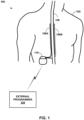
- FIG. 1 is a conceptual diagram illustrating example system 100 that includes implantable medical device (IMD) 110 to deliver electrical stimulation therapy to patient 102.
- IMD implantable medical device
- FIG. 1 is a conceptual diagram illustrating example system 100 that includes implantable medical device (IMD) 110 to deliver electrical stimulation therapy to patient 102.
- IMD implantable medical device
- FIG. 1 will refer to an implantable SCS system for purposes of illustration, but without limitation as to other types of medical devices or other therapeutic applications of medical devices.
- system 100 includes an IMD 110, leads 108A and 108B, and external programmer 104 shown in conjunction with a patient 102, who is ordinarily a human patient.
- IMD 110 is an implantable electrical stimulator that is configured to generate and deliver electrical stimulation therapy to patient 102 via one or more electrodes of electrodes of leads 108A and/or 108B (collectively, "leads 108"), e.g., for relief of chronic pain or other symptoms.
- leads 108 collectively, for relief of chronic pain or other symptoms.
- IMD 110 may be coupled to a single lead carrying multiple electrodes or more than two leads each carrying multiple electrodes.
- the stimulation signals, or pulses may be configured to elicit detectable ECAP signals that IMD 110 may use to determine the posture state occupied by patient 102 and/or determine how to adjust one or more parameters that define stimulation therapy.
- IMD 110 may be a chronic electrical stimulator that remains implanted within patient 102 for weeks, months, or even years. In other examples, IMD 110 may be a temporary, or trial, stimulator used to screen or evaluate the efficacy of electrical stimulation for chronic therapy.
- IMD 110 is implanted within patient 102, while in another example, IMD 110 is an external device coupled to percutaneously implanted leads. In some examples, IMD 110 uses one or more leads, while in other examples, IMD 110 is leadless.
- IMD 110 may be constructed of any polymer, metal, or composite material sufficient to house the components of IMD 110 (e.g., components illustrated in FIG. 2 ) within patient 102.
- IMD 110 may be constructed with a biocompatible housing, such as titanium or stainless steel, or a polymeric material such as silicone, polyurethane, or a liquid crystal polymer, and surgically implanted at a site in patient 102 near the pelvis, abdomen, or buttocks.
- IMD 110 may be implanted within other suitable sites within patient 102, which may depend, for example, on the target site within patient 102 for the delivery of electrical stimulation therapy.
- the outer housing of IMD 110 may be configured to provide a hermetic seal for components, such as a rechargeable or non-rechargeable power source.
- the outer housing of IMD 110 is selected from a material that facilitates receiving energy to charge the rechargeable power source.
- Electrical stimulation energy which may be constant current or constant voltage-based pulses, for example, is delivered from IMD 110 to one or more target tissue sites of patient 102 via one or more electrodes (not shown) of implantable leads 108.
- leads 108 carry electrodes that are placed adjacent to the target tissue of spinal cord 106.
- One or more of the electrodes may be disposed at a distal tip of a lead 108 and/or at other positions at intermediate points along the lead.
- Leads 108 may be implanted and coupled to IMD 110.
- the electrodes may transfer electrical stimulation generated by an electrical stimulation generator in IMD 110 to tissue of patient 102.
- leads 108 may each be a single lead, lead 108 may include a lead extension or other segments that may aid in implantation or positioning of lead 108.
- IMD 110 may be a leadless stimulator with one or more arrays of electrodes arranged on a housing of the stimulator rather than leads that extend from the housing.
- system 100 may include one lead or more than two leads, each coupled to IMD 110 and directed to similar or different target tissue sites.
- the electrodes of leads 108 may be electrode pads on a paddle lead, circular (e.g., ring) electrodes surrounding the body of the lead, conformable electrodes, cuff electrodes, segmented electrodes (e.g., electrodes disposed at different circumferential positions around the lead instead of a continuous ring electrode), any combination thereof (e.g., ring electrodes and segmented electrodes) or any other type of electrodes capable of forming unipolar, bipolar or multipolar electrode combinations for therapy. Ring electrodes arranged at different axial positions at the distal ends of lead 108 will be described for purposes of illustration.
- electrodes via leads 108 are described for purposes of illustration, but arrays of electrodes may be deployed in different ways.
- a housing associated with a leadless stimulator may carry arrays of electrodes, e.g., rows and/or columns (or other patterns), to which shifting operations may be applied.
- Such electrodes may be arranged as surface electrodes, ring electrodes, or protrusions.
- electrode arrays may be formed by rows and/or columns of electrodes on one or more paddle leads.
- electrode arrays include electrode segments, which are arranged at respective positions around a periphery of a lead, e.g., arranged in the form of one or more segmented rings around a circumference of a cylindrical lead.
- one or more of leads 108 are linear leads having 8 ring electrodes along the axial length of the lead.
- the electrodes are segmented rings arranged in a linear fashion along the axial length of the lead and at the periphery of the lead.
- the stimulation parameter set of a stimulation program that defines the stimulation pulses of electrical stimulation therapy by IMD 110 through the electrodes of leads 108 may include information identifying which electrodes have been selected for delivery of stimulation according to a stimulation program, the polarities of the selected electrodes, i.e., the electrode combination for the program, voltage or current amplitude, pulse frequency, pulse width, pulse shape of stimulation delivered by the electrodes.
- These stimulation parameters values that make up the stimulation parameter set that defines pulses may be predetermined parameter values defined by a user and/or automatically determined by system 1 00 based on one or more factors or user input. Informed pulses may be defined by a set of informed stimulation parameter values and control pulses may be defined by a set of control stimulation parameter values.
- system 100 may be configured to treat any other condition that may benefit from electrical stimulation therapy.
- system 100 may be configured to provide multimodal stimulation using prime stimulation and base stimulation together.
- system 100 may be used to treat tremor, Parkinson's disease, epilepsy, a pelvic floor disorder (e.g., urinary incontinence or other bladder dysfunction, fecal incontinence, pelvic pain, bowel dysfunction, or sexual dysfunction), obesity, gastroparesis, or psychiatric disorders (e.g., depression, mania, obsessive compulsive disorder, anxiety disorders, and the like).
- tremor e.g., Parkinson's disease, epilepsy, a pelvic floor disorder (e.g., urinary incontinence or other bladder dysfunction, fecal incontinence, pelvic pain, bowel dysfunction, or sexual dysfunction), obesity, gastroparesis, or psychiatric disorders (e.g., depression, mania, obsessive compulsive disorder, anxiety disorders, and the
- system 100 may be configured to provide therapy taking the form of deep brain stimulation (DBS), peripheral nerve stimulation (PNS), peripheral nerve field stimulation (PNFS), cortical stimulation (CS), pelvic floor stimulation, gastrointestinal stimulation, or any other stimulation therapy capable of treating a condition of patient 102.
- DBS deep brain stimulation
- PNS peripheral nerve stimulation
- PNFS peripheral nerve field stimulation
- CS cortical stimulation
- pelvic floor stimulation gastrointestinal stimulation, or any other stimulation therapy capable of treating a condition of patient 102.
- lead 108 includes one or more sensors configured to allow IMD 110 to monitor one or more parameters of patient 102, such as patient activity, pressure, temperature, or other characteristics.
- the one or more sensors may be provided in addition to, or in place of, therapy delivery by lead 108.
- IMD 110 is generally configured to deliver electrical stimulation therapy (e.g., informed pulses and/or control pulses in the form of a prime pulse train and base pulse train, respectively) to patient 102 via selected combinations of electrodes carried by one or both of leads 108, alone or in combination with an electrode carried by or defined by an outer housing of IMD 110.
- the target tissue for the electrical stimulation therapy may be any tissue affected by electrical stimulation, which may be in the form of electrical stimulation pulses or continuous waveforms.
- the target tissue includes nerves, smooth muscle or skeletal muscle. In the example illustrated by FIG.
- stimulation of spinal cord 106 or other anatomical structures associated with the spinal cord may provide relief from symptoms that may not produce paresthesia.
- IMD 110 may deliver stimulation with intensities (e.g., values of amplitude and/or pulse width) below a sensory or perception threshold (e.g., sub-threshold stimulation) that reduces pain without paresthesia.
- intensities e.g., values of amplitude and/or pulse width
- sub-threshold stimulation e.g., sub-threshold stimulation
- IMD 110 may deliver one pulse train at a higher frequency via one electrode combination and a second pulse train on an interleaved basis with a lower frequency via a second electrode combination, where both pulse trains are delivered at a sub-threshold intensity.
- IMD 110 is configured to generate and deliver electrical stimulation therapy to a target stimulation site within patient 102 via the electrodes of leads 108 to patient 102 according to one or more therapy stimulation programs.
- a therapy stimulation program may generally define informed pulses, but may also define control pulses if the control pulses also contribute to a therapeutic effect).
- a therapy stimulation program defines values for one or more parameters (e.g., a parameter set) that define an aspect of the therapy delivered by IMD 110 according to that program.
- a therapy stimulation program that controls delivery of stimulation by IMD 110 in the form of pulses may define values for voltage or current pulse amplitude, pulse width, pulse rate (e.g., pulse frequency), electrode combination, pulse shape, etc. for stimulation pulses delivered by IMD 110 according to that program.
- external programmer 104 may be characterized as a physician or clinician programmer if it is primarily intended for use by a physician or clinician. In other cases, external programmer 104 may be characterized as a patient programmer if it is primarily intended for use by a patient.
- a patient programmer may be generally accessible to patient 102 and, in many cases, may be a portable device that may accompany patient 102 throughout the patient's daily routine. For example, a patient programmer may receive input from patient 102 when the patient wishes to terminate or change electrical stimulation therapy, or when a patient perceives stimulation being delivered.
- IMD 110 and external programmer 104 may communicate via wireless communication using any techniques known in the art. Examples of communication techniques may include, for example, radiofrequency (RF) telemetry and inductive coupling, but other techniques are also contemplated.
- external programmer 104 includes a communication head that may be placed proximate to the patient's body near the IMD 110 implant site to improve the quality or security of communication between IMD 110 and external programmer 104. Communication between external programmer 104 and IMD 110 may occur during power transmission or separate from power transmission.
- IMD 110 in response to commands from external programmer 104, delivers electrical stimulation therapy (e.g., informed pulses and/or control pulses) according to a plurality of therapy stimulation programs to a target tissue site of the spinal cord 106 of patient 102 via electrodes (not depicted) on leads 108.
- IMD 1 10 modifies therapy stimulation programs as therapy needs of patient 102 evolve over time. For example, the modification of the therapy stimulation programs may cause the adjustment of at least one parameter of the plurality of stimulation pulses. When patient 102 receives the same therapy for an extended period, the efficacy of the therapy may be reduced. In some cases, parameters of the plurality of stimulation pulses may be automatically updated.
- Efficacy of electrical stimulation therapy may be indicated by one or more characteristics (e.g. an amplitude of or between one or more peaks or an area under the curve of one or more peaks) of an action potential that is evoked by a control pulse delivered by IMD 110 (i.e., a characteristic value of the ECAP signal).
- Electrical stimulation therapy delivery by leads 108 of IMD 110 may cause neurons within the target tissue to evoke a compound action potential that travels up and down the target tissue, eventually arriving at sensing electrodes of IMD 110.
- stimulation may also elicit at least one ECAP signal, and ECAPs responsive to stimulation may also be a surrogate for the effectiveness of the therapy.
- the amount of action potentials (e.g., number of neurons propagating action potential signals) that are evoked may be based on the various parameters of electrical stimulation pulses such as amplitude, pulse width, frequency, pulse shape (e.g., slew rate at the beginning and/or end of the pulse), etc.
- the slew rate may define the rate of change of the voltage and/or current amplitude of the control pulse at the beginning and/or end of each control pulse or each phase within the pulse. For example, a very high slew rate indicates a steep or even near vertical edge of the pulse, and a low slew rate indicates a longer ramp up (or ramp down) in the amplitude of the control pulse.
- these parameters contribute to an intensity of the electrical stimulation.
- a characteristic of the ECAP signal (e.g., an amplitude) may change based on the distance between the stimulation electrodes and the nerves subject to the electrical field produced by the delivered control pulses.
- Some example techniques for adjusting stimulation parameter values for stimulation pulses are based on comparing the value of a characteristic of a measured ECAP signal to a target ECAP characteristic value.
- IMD 110 In response to delivering a control pulse defined by a set of stimulation parameter values, IMD 110, via two or more electrodes interposed on leads 108, senses electrical potentials of tissue of the spinal cord 106 of patient 102 to measure the electrical activity of the tissue. IMD 110 senses ECAPs from the target tissue of patient 102, e.g., with electrodes on one or more leads 108 and associated sense circuitry.
- IMD 110 receives a signal indicative of the ECAP from one or more sensors, e.g., one or more electrodes and circuitry, internal or external to patient 102.
- a signal indicative of the ECAP may include a signal indicating an ECAP of the tissue of patient 102.
- the one or more sensors include one or more sensors configured to measure a compound action potential of patient 102, or a physiological effect indicative of a compound action potential.
- the one or more sensors may be an accelerometer, a pressure sensor, a bending sensor, a sensor configured to detect a posture of patient 102, or a sensor configured to detect a respiratory function of patient 102.
- external programmer 104 receives a signal indicating a compound action potential in the target tissue of patient 102 and transmits a notification to IMD 110.
- IMD 110 is described as performing a plurality of processing and computing functions. However, external programmer 104 instead may perform one, several, or all of these functions. In this alternative example, IMD 110 functions to relay sensed signals to external programmer 104 for analysis, and external programmer 104 transmits instructions to IMD 110 to adjust the one or more parameters defining the electrical stimulation therapy based on analysis of the sensed signals. For example, IMD 110 may relay the sensed signal indicative of an ECAP to external programmer 104.
- External programmer 104 may compare the parameter value of the ECAP to the target ECAP characteristic value, and in response to the comparison, external programmer 104 may instruct IMD 110 to adjust one or more stimulation parameter that defines the electrical stimulation informed pulses and, in some examples, control pulses, delivered to patient 102.
- the system changes the target ECAP characteristic value and/or growth rate(s) over a period of time, such as according to a change to a stimulation threshold (e.g., a perception threshold or detection threshold specific for the patient).
- a stimulation threshold e.g., a perception threshold or detection threshold specific for the patient.
- the system may be programmed to change the target ECAP characteristic in order to adjust the intensity of informed pulses to provide varying sensations to the patient (e.g., increase or decrease the volume of neural activation).
- received ECAP signals may still be used by the system to adjust one or more parameter values of the informed pulses and/or control pulses in order to meet the target ECAP characteristic value.
- IMD 110 may include stimulation circuitry configured to deliver electrical stimulation, sensing circuitry configured to sense a plurality ECAP signals, and processing circuitry.
- the processing circuitry may be configured to control the stimulation circuitry to deliver a plurality of electrical stimulation pulses (e.g., control pulses) having different amplitude values and control the sensing circuitry to detect, after delivery of each electrical stimulation pulse of the plurality of electrical stimulation pulses, a respective ECAP signal of the plurality of ECAP signals.
- IMD 110 may modulate or adjust one or more stimulation parameters that at least partially define electrical stimulation based on a sensed ECAP signals to employ a closed-loop feedback system for adjusting stimulation parameters that define informed pulses and/or control pulses.
- IMD 110 includes stimulation generation circuitry configured to generate and deliver electrical stimulation to patient 102 according one or more sets of stimulation parameters (e.g., informed parameters and/or control parameters) that at least partially define the respective informed pulses and/or control pulses of the electrical stimulation.
- Each set of stimulation parameters may include at least one of an amplitude, a pulse width, a pulse frequency, or a pulse shape.
- IMD 110 may also include sensing circuitry configured to sense an ECAP signal elicited by delivered electrical stimulation, such as a control pulse. IMD 110 may also include processing circuitry configured to control delivery of an informed pulses to patient 102 according to a first value of an informed stimulation parameter and determine a characteristic value of the ECAP signal detected from the control pulse. IMD 110 may also receive, from a sensor, a posture state signal representing a posture state of the patient. In some examples, IMD 110 may then determine, based on the posture state signal, a gain value for the stimulation parameter and adjust, based on the characteristic value of the ECAP signal and the gain value, the first value of the informed stimulation parameter to a second value of the informed stimulation parameter.
- sensing circuitry configured to sense an ECAP signal elicited by delivered electrical stimulation, such as a control pulse.
- IMD 110 may also include processing circuitry configured to control delivery of an informed pulses to patient 102 according to a first value of an informed stimulation parameter and determine a characteristic value of the ECAP signal detected from the
- IMD 110 may additionally, or alternatively, adjust a target ECAP characteristic value or a threshold ECAP characteristic value based on the posture state signal. IMD 110 may then control subsequent delivery of one or more informed stimulation pulses according to the second value of the informed stimulation parameter. In this manner, an informed parameter value that defines the next informed pulse was "informed" by the ECAP signal elicited by a control pulse.
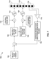
- IMD 110 may perform an example process. For example, IMD 110 may monitor an amplitude that is the characteristic value of the detected ECAP signal. IMD 110 may adjust the first value to the second value of the informed stimulation parameter by subtracting the amplitude from a target ECAP amplitude value for the patient to generate a differential amplitude. The differential amplitude is the difference between the detected amplitude from the ECAP signal and the target ECAP amplitude value. IMD 110 may then multiply the differential amplitude by the gain value that at least partially defines the control pulses to generate a differential value. The gain value may be a multiplier or fraction.
- a larger gain value may be associated with posture states at which the distance between electrodes and the target nerve is larger because the distance causes less sensitivity for changes in stimulation pulse intensity.
- IMD 110 may then add the differential value to a previous amplitude value (e.g., the amplitude value of the last control pulse that was delivered and elicited the ECAP signal) to generate the second value that at least partially defines the next control pulse to be delivered to patient 102.
- IMD 110 may then multiple the differential value by a scaling factor to generate an informed differential value representing how much the amplitude of the informed pulses needs to change.
- the scaling factor may be greater than one when the informed pulse amplitude is greater than the control pulse amplitude, and conversely, the scaling factor may be less than one when the informed pulse amplitude is less than the control pulse amplitude.
- IMD 110 can then add the informed differential value to the previous amplitude value of the informed pulses to generate a second value of the informed pulses for subsequent delivery to the patient.
- IMD 110 may not attempt to maintain consistent nerve activation by modulating stimulation pulses to achieve a target ECAP characteristic value. Instead, IMD 110 may monitor characteristic values of ECAP signals and only take action when the characteristic value exceeds a threshold ECAP characteristic value. Characteristic values exceeding the threshold ECAP characteristic values may be indicative of increased stimulation perception that may be above an uncomfortable threshold or pain threshold for the patient. Therefore, reducing stimulation pulse intensity when the characteristic value exceeds this level of stimulation may reduce the likelihood that patient 102 experiences any uncomfortable sensations that may occur as a result of posture state changes or any transient movement. For example, IMD 110 may be configured to compare the characteristic value of the ECAP signal to a threshold ECAP characteristic value and determine that the characteristic value of the ECAP signal is greater than the threshold ECAP characteristic value.
- IMD 110 may be configured to decrease the first value of the informed stimulation parameter to the second value of the informed stimulation parameter for subsequent informed pulses to be delivered. Similarly, IMD 110 may be configured to decrease the value of a control stimulation parameter that defines subsequent control pulses to be delivered.
- IMD 110 may continue to decrease the informed stimulation parameter value and/or the control stimulation parameter value as long as the ECAP characteristic value continues to exceed the threshold ECAP characteristic value. Once, the informed and control stimulation parameters have been decreased, IMD 110 may attempt to increase the informed and control stimulation parameter values again back up to the predetermined first value intended for the informed stimulation pulses and/or control stimulation pulses. IMD 110 may be configured to determine a other characteristic values of subsequent ECAP signals elicited from control stimulation pulses delivered after sensing the first ECAP signal.
- IMD 110 may then increase the value of the informed and/or control stimulation parameter back up to a value limited to be less than or equal to the first value (e.g., back up to the predetermined value for the informed and/or control stimulation pulses that may be determined by a set of stimulation parameters or therapy program).
- IMD 110 may iteratively increase the informed and/or control stimulation parameter values until the first value, or original value, is again reached after the characteristic values of the ECAP signal remain below the threshold ECAP characteristic value.
- IMD 110 may increase the informed and/or control stimulation parameter values at a slower rate than the informed and/or control stimulation parameter values are decreased, but, in other examples, IMD 110 may increase and decrease the informed and/or control stimulation parameters at the same rates.
- some example techniques for adjusting informed stimulation parameter values and/or control stimulation parameter values for electrical stimulation signals are based on comparing the value of a characteristic of a measured ECAP signal to a target ECAP characteristic value or using control parameter values at a determined target ECAP characteristic to inform adjustment of one or more control parameter values and/or informed parameter values to maintain the target ECAP according to known relationships between parameters.
- IMD 110 via two or more electrodes interposed on leads 108, senses electrical potentials of tissue of the spinal cord 106 of patient 102 to measure the electrical activity of the tissue.
- IMD 110 senses ECAPs from the target tissue of patient 102, e.g., with electrodes on one or more leads 108 and associated sensing circuitry.
- IMD 110 receives a signal indicative of the ECAP from one or more sensors, e.g., one or more electrodes and circuitry, internal or external to patient 102.
- a signal indicative of the ECAP may include a signal indicating an ECAP of the tissue of the patient 102.
- the one or more sensors include one or more sensors can measure a compound action potential of the patient 102, or a physiological effect indicative of a compound action potential.
- the one or more sensors may be an accelerometer, a pressure sensor, a bending sensor, a sensor can detect a posture of patient 102, or a sensor can detect a respiratory function of patient 102.
- external programmer 104 receives a signal indicating a compound action potential in the target tissue of patient 102 and transmits a notification to IMD 110.
- IMD 110 described as performing a plurality of processing and computing functions.
- external programmer 104 instead may perform one, several, or all of these functions.
- IMD 110 functions to relay sensed signals to external programmer 104 for analysis, and external programmer 104 transmits instructions to IMD 110 to adjust the one or more parameters defining the electrical stimulation signal based on analysis of the sensed signals.
- IMD 110 may relay the sensed signal indicative of an ECAP to external programmer 104.
- External programmer 104 may compare the parameter value of the ECAP to the target ECAP characteristic value, and in response to the comparison, external programmer 104 may instruct IMD 110 to adjust one or more parameters that define the electrical stimulation signal.
- the informed stimulation parameter values, control stimulation parameter values, growth curves, posture states, and the target ECAP characteristic values may be initially set at the clinic but may be set and/or adjusted at home by patient 102.
- the example techniques allow for automatic adjustment of informed and/or control stimulation parameters to maintain consistent volume of neural activation and consistent perception of therapy for the patient when the electrode-to-neuron distance changes.
- the ability to change the stimulation parameter values may also allow the therapy to have long term efficacy, with the ability to keep the intensity of the stimulation (e.g., as indicated by the ECAP) consistent by comparing the measured ECAP values to the target ECAP characteristic value.
- IMD 110 may perform these changes without intervention by a physician or patient 102.
- the system may change the target ECAP characteristic value over a period of time (e.g., based on a sensed posture state or change in patient conditions).
- the system may be programmed to change the target ECAP characteristic in order to adjust the intensity of the informed pulses and/or control pulses to provide varying sensations to the patient (e.g., increase or decrease the volume of neural activation).
- a system may be programmed to oscillate a target ECAP characteristic value between a maximum target ECAP characteristic value and a minimum target ECAP characteristic value at a predetermined frequency to provide a sensation to the patient that may be perceived as a wave or other sensation that may provide therapeutic relief for the patient.
- the maximum target ECAP characteristic value, the minimum target ECAP characteristic value, and the predetermined frequency may be stored in the memory of IMD 110 and may be updated in response to a signal from external programmer 104 (e.g., a user request to change the values stored in the memory of IMD 110).
- the target ECAP characteristic value may be programed to steadily increase or steadily decrease to a baseline target ECAP characteristic value over a period of time.
- external programmer 104 may program the target ECAP characteristic value to automatically change over time according to other predetermined functions or patterns.
- the target ECAP characteristic value may be programmed to change incrementally by a predetermined amount or predetermined percentage, the predetermined amount or percentage being selected according to a predetermined function (e.g., sinusoid function, ramp function, exponential function, logarithmic function, or the like). Increments in which the target ECAP characteristic value is changed may be changed for every certain number of pulses or a certain unit of time. Although the system may change the target ECAP characteristic value, received ECAP signals may still be used by the system to adjust one or more informed and/or control parameter values of the electrical stimulation signal in order to meet the target ECAP characteristic value.
- a predetermined function e.g., sinusoid function, ramp function, exponential function, logarithmic function, or the like.
- IMD 110 can be configured to provide therapy to a patient (e.g., pain relief therapy) by using multimodal stimulation (e.g., differential targeted multiplexed stimulation).
- multimodal stimulation e.g., differential targeted multiplexed stimulation.
- Multiple modal stimulation includes different pulse trains (e.g., a prime pulse train and a base pulse train) defined by different stimulation parameters such as different frequencies and different electrode combinations. Since different types of cells, such as glial cells and neurons, respond differently to electrical fields, it is then possible to differentially modulate the response of these cell populations with distinctly different electrical parameters.
- the prime pulse train can be delivered to affect glial cells and the base pulse train can be delivered to affect neurons.
- the prime pulse train is delivered at a higher pulse frequency than the base pulse train, as described herein.
- the oscillatory electromagnetic fields applied to neural structures can induce changes in synaptic plasticity upon modulation of two different cell populations: neurons and glial cells. This is concurrent with the effects on neurons such as action potential generation or blockade by the stimulation of mechanosensitive fibers to mask (or close the gate to) nociceptive signals travelling to the brain.
- glial cells are immunocompetent cells that constitute the most common cell population in the nervous system and play a fundamental role in the development and maintenance of chronic neuropathic pain. Glial cells are responsible for monitoring the status of the nervous system by using constant chemical communication with neurons and other glial cells.
- Microglia are the glial cells in charge of monitoring the brain and spinal cord.
- CNS Central Nervous System
- Astrocyte activation and regulation is sustained for longer time and thus it can be hypothesized that astrocytes play an important role in changes affecting synaptic plasticity in chronic pain.
- PNS Peripheral Nervous System
- oligodendrocytes oligodendrocytes
- Schwann cells oligodendrocytes
- satellite glial cells similar to astroglia
- glial depolarization glial depolarization, release/uptake of ions, release of glial transmitters
- response depends on the specific parameters such as amplitude, frequency, phase polarity, waveform shape, and width (in the case of rectangular waveforms) of the stimulation.
- the release of glutamate from astrocytes may be modulated in proportion to the amount of anodic current administered during biphasic pulsed stimulation.
- Monophasic cathodic stimulation of hippocampal astrocytes promotes the release of glutamate.
- the introduction of an anodic component decreases the amount of glutamate released.
- glial cells and neurons respond differently to electrical fields; it is then possible to differentially modulate the response of these cell populations with distinctly different electrical parameters.
- This theory sets a mechanistic basis of multimodal stimulation.
- Subthreshold stimulation with an electromagnetic field set at an optimum frequency, amplitude, waveform, width and phase may modulate the behavior of glial cells and the way they interact with neurons at the synaptic level.
- multimodal modulation provides the ability to control the balance of glutamate and glutamine in a calcium dependent manner and the possibility of modulating such balance in the appropriate manner with electromagnetic fields.
- SCS was identified to have upregulated genes for calcium binding proteins (Cabp), cytokines (Tnf, 116, 111b, Cxcl16, 1fg), cell adhesion (1tgb) and specific immune response proteins (Cd68, Tlr2), all of which have been linked to glial activation.
- Modulation parameters particularly the oscillation frequency and amplitude, may play an important role in the mode of action.
- the Priming Frequency may be set to any frequency between 100 Hz to 1200 kHz. However, higher or lower frequencies may be used in other examples.
- the Pulse Width (PW) of the priming component may be set as low as 10 us and as large as allowed by the priming frequency. In some examples, the PW of pulses may be between approximately 150 to 300 ⁇ s, although other examples may have smaller or larger pulse widths. Either a voltage or current controlled composite signal may be used, although a current controlled signal may be more desirable as such signal does not depend on temporal impedance variations in the tissue being stimulated.
- a second or tonic component is set at a frequency of about 50 Hz, interleaved into the treatment to account for the average priming frequency, though other tonic values and ranges are contemplated herein, e.g., 20 Hz to 2.00 Hz, 20 Hz to 100 Hz, 30 Hz to 80 Hz, etc.
- the IMD 110 may be configured to sensed ECAP signals after one or more pulses of the tonic component (e.g., a base pulse train) and before the next subsequent pulse of the tonic component to inform any adjustments to a parameter defining the priming stimulation or other aspect of the overall multimodal stimulation or closed-loop control of the stimulation.
- IMD 110 may be configured to provide automatic closed-loop control of such stimulation based on sensed ECAP signals.
- Multimodal modulation for pain management contemplates the use of oscillating electromagnetic fields which is applied via an array of electrodes (referred as contacts or leads) to a particular neural structure using temporal and amplitude characteristics, to modulate glial and neuronal interactions as the mechanism for relieving chronic pain.
- exemplary aspects provide an apparatus and method for modulating the expression of genes involved in diverse pathways including inflammatory/immune system mediators, ion channels and neurotransmitters, in both the Spinal Cord (SC) and Dorsal Root Ganglion (DRG).
- expression modulation is caused by spinal cord stimulation or peripheral nerve stimulation.
- the amplitudes and frequencies of the signal or signals used to create the multimodal stimulation of neural structures may be optimized for pain relief and low power usage in an implantable multimodal signal generator, as described herein.
- apparatuses and methods provide for managing pain in a patient by using multiplexed stimulation signals to target different neural structures such that the multiple stimulation signals are multiplexed in the time domain, hereafter referred to as multimodal stimulation or "differential target multiplexed stimulation.”
- a signal generator can multiplex signals (e.g., pulses from different pulse trains) that can have different signal characteristics (e.g., pulse frequency, amplitude, or pulse duration) to generate differential target multiplexed stimulation for pain management.
- the output of the signal generator can be used to produce separate oscillating electromagnetic fields (stimulation signals, such as pulses or continuous signals) which can be applied to different set of a plurality of electrodes (also referred as contacts).
- the electrodes can be part of a lead that is designed to apply the respective stimulation signals to different parts of a particular neural structure.
- the multiplexed stimulation signals have characteristics that allow for a synergistic targeting of glial cells and neurons in a differential manner.
- IMD 200 can modulate the expression of genes and proteins involved in diverse pathways, including inflammatory/immune system mediators, ion channels and neurotransmitters, associated with the interaction of glia and neurons in neural tissue.
- expression modulation may be caused by any of spinal cord stimulation, dorsal root ganglion stimulation, brain stimulation, or peripheral nerve stimulation.
- the amplitudes, phase polarity, waveforms, and frequencies of the signals combined to create the differential target multiplexed stimulation of neural structures may be optimized for pain relief and low power usage in an implantable signal generator, as described herein.
- a set of high frequency charge-balanced biphasic pulsed signals (e.g., one or more first pulse trains or prime pulse trains) in which the polarity of the first phase of the high frequency signals may be either cathodic or anodic is utilized.
- a set of low frequency signals (e.g., one or more second pulse trains or base pulse trains) is used that may have waveform characteristics different from those of the high frequency signals.
- the polarity of the first phase of the biphasic charge-balanced low frequency signals may be either cathodic or anodic.
- the high and low frequency stimulation signals can be delivered to the neural tissues by multiplexing individual pulses from each via respective sets of electrodes.
- the respective sets of electrodes can be co-located in close proximity to the same neural tissue (e.g., near the same vertebrae).
- electrical stimulation is generally described herein in the form of electrical stimulation pulses, electrical stimulation may be delivered in non-pulse form in other examples.
- electrical stimulation may be delivered as a signal having various waveform shapes, frequencies, and amplitudes. Therefore, electrical stimulation in the form of a non-pulse signal may be a continuous signal than may have a sinusoidal waveform or other continuous waveform.
- various multi-contact leads can be positioned in the epidural space to stimulate the cell populations already described.
- the leads can be positioned parallel to each other, although not necessarily coplanar within the epidural space.
- Two eight-contact electrode arrays can be used for the disclosed multimodal modulation techniques.
- the polarity of the leads can also be customized during the programming stage, either as bipolar, monopolar, or guarded cathode configurations.
- Another example of a possible electrode array arrangement includes leads arranged staggered relative to each other. The customization and optimization of therapy may comprise the positioning of the leads within the epidural space at appropriate vertebral segments in either type of lead arrangement.
- one lead can be dedicated to deliver a signal at the spinal cord at a given vertebral level, while the other provides a signal either more caudad or cephalad relative to the position of the other lead.
- Leads can be, in principle, located at any vertebral level in the spinal cord, or could also be positioned peripherally, because the principle behind multimodal modulation applies to peripheral glial cells that survey the axons.
- the multimodal stimulation electromagnetic fields location and penetration may be also utilized for customization and optimization of therapy by delivering multimodal stimulation signals to particular arrays of electrodes within each lead by setting monopolar, bipolar, or guarded cathode arrangements of such electrode arrays.
- therapy for a patient with low back pain that extends into one of the lower extremities may require positioning the stimulation leads in a staggered arrangement within the epidural space along vertebral levels thoracic 8 (TS) and thoracic 12 (T12).
- An array of electrodes in the more cephalad of the leads may be set to monopolar, bipolar or guarded cathode arrangement.
- Another array of electrodes in the more caudad of the leads may be set to monopolar, bipolar or guarded cathode arrangement.
- the clinician will be able to customize the electrode array setting in a methodical manner such that therapy can be optimized for based on feedback from the patient.
- pain relief may also be used by position the leads in the neighborhood of a peripheral nerve.
- Peripheral Nerve Stimulation is an alternative therapy for chronic pain in which a target nerve has been identified to be the source of pain.
- the current understanding of the therapeutic effects of PNS is also based on the gate control theory.
- axons of sensory neurons in peripheral nerves are surrounded by glial cells that are known to respond accordingly to the frequency characteristics of a stimulus.
- Multimodal peripheral nerve stimulation involves the positioning of one or more stimulation leads around or in the neighborhood of a target nerve.
- the leads are connected to a signal generator with multimodal capacity as described herein.
- Multimodal stimulation is delivered to the neural tissue consisting of neuron axons and their corresponding glial cells (Schwann cells) according to the principles and methods described in this application.
- the leads may be implanted and positioned around the target nerve using an invasive surgical approach or percutaneously utilizing a needle cannula.
- the leads may be arranged inside a conductive biocompatible pad for delivery of the multimodal electromagnetic field transcutaneously.
- This embodiment constitutes Transcutaneous Electrical Nerve Multimodal Stimulation (TENMS).
- TENMS Transcutaneous Electrical Nerve Multimodal Stimulation
- the priming high frequency component of the multimodal signal lowers the impedance of the skin and subcutaneous tissue and allows for better penetration of the tonic signal.
- the priming signal also provides a modulating signal for perisytiaptic glial cells in the neuromuscular junction. These cells are known to discriminate different stimulation patterns and respond accordingly, thus allowing for modulation of the synapse with multimodal stimulation.
- the tonic component of the multimodal signal is used to stimulate the neuronal axon at lower thresholds.
- IMD 1 10 takes the form of an SCS device
- IMD 110 takes the form of any combination of deep brain stimulation (DBS) devices, implantable cardioverter defibrillators (ICDs), pacemakers, cardiac resynchronization therapy devices (CRT-Ds), left ventricular assist devices (LVADs), implantable sensors, orthopedic devices, or drug pumps, as examples.
- DBS deep brain stimulation
- ICDs implantable cardioverter defibrillators
- pacemakers pacemakers
- CRT-Ds cardiac resynchronization therapy devices
- LVADs left ventricular assist devices
- implantable sensors implantable sensors
- orthopedic devices or drug pumps
- FIG. 2 is a block diagram of IMD 2.00.
- IMD 2.00 may be an example of IMD 110 of FIG. 1 .
- IMD 200 includes switch circuitry 202, stimulation generation circuitry 204, sensing circuitry 206, processing circuitry 208, sensor 210, telemetry circuitry 212, power source 214, and memory 216.
- Each of these circuits may be or include programmable or fixed function circuitry can perform the functions attributed to respective circuitry.
- processing circuitry 208 may include fixed-function or programmable circuitry
- stimulation generation circuitry 204 may include circuitry can generate electrical stimulation signals such as pulses or continuous waveforms on one or more channels
- sensing circuitry 206 may include sensing circuitry for sensing signals
- telemetry circuitry 212 may include telemetry circuitry for transmission and reception of signals.
- Memory 216 may store computer-readable instructions that, when executed by processing circuitry 208, cause IMD 200 to perform various functions described herein. Memory 216 may be a storage device or other non-transitory medium.
- memory 216 stores patient data 218, which may include anything related to the patient such as one or more patient postures, an activity level, or a combination of patient posture and activity level.
- Memory 216 may store stimulation parameter settings 220 within memory 216 or separate areas within memory 216.
- Each stored stimulation parameter setting 220 defines values for one or more sets of electrical stimulation parameters (e.g., an informed stimulation parameter set and a control stimulation parameter set, or parameters for other pulse trains), such as pulse amplitude, pulse width, pulse frequency, electrode combination, pulse burst rate, pulse burst duration, and/or waveform shape.
- Stimulation parameter settings 220 may also include additional information such as instructions regarding delivery of electrical stimulation signals based on stimulation parameter relationship data, which can include relationships between two or more stimulation parameters based upon data from electrical stimulation signals delivered to patient 102 or data transmitted from external programmer 104.
- the stimulation parameter relationship data may include measurable aspects associated with stimulation, such as an ECAP characteristic value.
- Stimulation parameter settings 220, or another portion of memory 216 may include instructions on how processing circuitry 208 can modulate informed stimulation parameters and/or control stimulation parameters based on the detected posture state and/or at least one of a target ECAP characteristic value or a threshold ECAP characteristic value, as described herein.
- Memory 216 also stores patient ECAP characteristics 222 which may include target ECAP characteristics and/or threshold ECAP characteristic values determined for the patient and/or a history of measured ECAP characteristic values for the patient. Memory 216 may also control policy data 224 in separate areas from or as part of patient stimulation parameter settings. Control policy data 224 may include instructions that processing circuitry 208 uses for how to adjust one or more parameter values that define stimulation in response to ECAP characteristic values. Memory 216 may include gain values that processing circuitry 208 may use to modulate informed and/or control stimulation pulses as described herein.
- stimulation generation circuitry 204 generates electrical stimulation signals (e.g., informed pulses and control pulses) in accordance with the electrical stimulation parameters noted above. Other ranges of stimulation parameter values may also be useful and may depend on the target stimulation site within patient 102. While stimulation pulses are described, stimulation signals may be of any form, such as continuous-time signals (e.g., sine waves) or the like.
- Switch circuitry 202 may include one or more switch arrays, one or more multiplexers, one or more switches (e.g., a switch matrix or other collection of switches), or other electrical circuitry configured to direct stimulation signals from stimulation generation circuitry 204 to one or more of electrodes 232, 234, or directed sensed signals from one or more of electrodes 232, 234 to sensing circuitry 206.
- stimulation generation circuitry 204 and/or sensing circuitry 206 may include sensing circuitry to direct signals to and/or from one or more of electrodes 232, 234, which may or may not also include switch circuitry 202.
- Sensing circuitry 206 may be configured to monitor signals from any combination of electrodes 232, 234.
- sensing circuitry 206 includes one or more amplifiers, filters, and analog-to-digital converters.
- Sensing circuitry 206 may be used to sense physiological signals, such as ECAPs.
- sensing circuitry 206 detects ECAPs from a particular combination of electrodes 232, 234.
- the particular combination of electrodes for sensing ECAPs includes different electrodes than a set of electrodes 232, 234 used to deliver control stimulation pulses and/or informed stimulation pulses.
- Processing circuitry 208 may include any one or more of a microprocessor, a controller, a digital signal processor (DSP), an application specific integrated circuit (ASIC), a field-programmable gate array (FPGA), discrete logic circuitry, or any other processing circuitry can provide the functions attributed to processing circuitry 208 herein may be embodied as firmware, hardware, software or any combination thereof.
- Processing circuitry 208 controls stimulation generation circuitry 204 to generate electrical stimulation signals according to stimulation parameter settings 220 stored in memory 216 to apply stimulation parameter values, such as pulse amplitude, pulse width, pulse frequency, and waveform shape of each of the electrical stimulation signals.
- Such a switch circuit may be a switch array, switch matrix, multiplexer, or any other type of switch circuitry can selectively couple stimulation energy to selected electrodes 232, 234 and to selectively sense bioelectrical neural signals of a spinal cord of the patient (not shown in FIG. 2 ) with selected electrodes 232, 234.
- stimulation electrodes at one end of a lead may deliver the control pulse and electrodes at the other end of the same lead may sense the ECAP signal without, or with minimal, interference from the control pulse itself.
- pulse width refers to the collective duration of every phase, and interphase interval when appropriate, of a single pulse.
- a single pulse may include a single phase in some examples (i.e., a monophasic pulse) or two or more phases in other examples (e.g., a bi-phasic pulse or a tri-phasic pulse).
Landscapes
- Health & Medical Sciences (AREA)
- Life Sciences & Earth Sciences (AREA)
- Nuclear Medicine, Radiotherapy & Molecular Imaging (AREA)
- Radiology & Medical Imaging (AREA)
- Neurology (AREA)
- Neurosurgery (AREA)
- Engineering & Computer Science (AREA)
- Biomedical Technology (AREA)
- Veterinary Medicine (AREA)
- Public Health (AREA)
- Animal Behavior & Ethology (AREA)
- General Health & Medical Sciences (AREA)
- Physiology (AREA)
- Biophysics (AREA)
- Electrotherapy Devices (AREA)
- Medicines Containing Plant Substances (AREA)
Claims (15)
- System, umfassend:
eine Verarbeitungsschaltungsanordnung (208), die ausgelegt ist zum:Steuern der Verabreichung einer ersten Folge elektrischer Stimulationsimpulse mit einer ersten Frequenz an ein erstes Zielgewebe;Steuern der Verabreichung einer zweiten Folge elektrischer Stimulationsimpulse mit einer zweiten Frequenz an ein zweites Zielgewebe, das sich von dem ersten Zielgewebe unterscheidet, wobei zumindest einige elektrische Stimulationsimpulse der ersten Folge elektrischer Stimulationsimpulse mit zumindest einigen elektrischen Stimulationsimpulsen der zweiten Folge elektrischer Stimulationsimpulse verschachtelt sind und wobei die erste Frequenz größer als die zweite Frequenz ist;Empfangen eines Signals eines evozierten zusammengesetzten Aktionspotentials (ECAP), das durch einen Impuls der zweiten Folge elektrischer Stimulationsimpulse ausgelöst wird;Einstellen eines ersten Wertes eines Parameters, der zumindest teilweise die erste Folge elektrischer Stimulationsimpulse definiert, basierend auf dem ECAP-Signal auf einen zweiten Wert; undin Reaktion auf das Einstellen des ersten Wertes des Parameters auf den zweiten Wert Steuern der Verabreichung der nachfolgenden Impulse der ersten Folge elektrischer Stimulationsimpulse gemäß dem zweiten Wert des Parameters. - System nach Anspruch 1, ferner umfassend eine Stimulationserzeugungsschaltungsanordnung, die zum Verabreichen der ersten Folge elektrischer Stimulationsimpulse und der zweiten Folge elektrischer Stimulationsimpulse ausgelegt ist, und wobei die Verarbeitungsschaltungsanordnung (208) so ausgelegt ist, dass sie die Stimulationserzeugungsschaltungsanordnung (204) zum Verabreichen der ersten Folge elektrischer Stimulationsimpulse und der zweiten Folge elektrischer Stimulationsimpulse steuert.
- System nach einem der Ansprüche 1 und 2, wobei der Parameter eines von Folgenden umfasst:eine Elektrodenkombination der ersten Folge elektrischer Stimulationsimpulse;eine Anzahl von Impulsen in der ersten Folge während eines Arbeitszyklus;die erste Frequenz von Impulsen in der ersten Folge;eine Amplitude von Impulsen in der ersten Folge;eine Impulsbreite von Impulsen in der ersten Folge;einen Frequenzmodulationsfaktor, der die erste Frequenz der ersten Folge moduliert;einen Amplitudenmodulationsfaktor, der die Amplitude der Impulse in der ersten Folge moduliert;ein Zwischenphasenintervall der Impulse in der ersten Folge;eine Impulsform der Impulse in der ersten Folge oder eine Polarität von Elektroden der ersten Folge.
- System nach einem der Ansprüche 1 bis 3, ferner umfassend eine Sensorschaltungsanordnung, die so ausgelegt ist, dass sie das ECAP-Signal erfasst, das durch den Impuls der zweiten Folge elektrischer Stimulationsimpulse ausgelöst wird.
- System nach Anspruch 4, wobei die Verarbeitungsschaltungsanordnung (208) so ausgelegt ist, dass sie aus dem ECAP-Signal einen charakteristischen Wert bestimmt, der eine ECAP-Amplitude eines Abschnitts des ECAP-Signals ist, wobei der Parameter eine Erste-Folge-Impulsamplitude der ersten Folge umfasst, wobei Impulse der zweiten Folge eine Amplitude der zweiten Folge umfassen, und wobei die Verarbeitungsschaltungsanordnung (208) ferner so ausgelegt ist, dass sie den ersten Wert des Parameters zumindest durch Folgendes auf den zweiten Wert des Parameters einstellt:Subtrahieren der ECAP-Amplitude von einem Ziel-ECAP-Amplitudenwert für den Patienten, um eine Differenzamplitude zu erzeugen;Multiplizieren der Differenzamplitude mit einem Verstärkungswert, um einen vorläufigen Differenzwert zu erzeugen;Multiplizieren des vorläufigen Differenzwerts mit einem Skalierungsfaktor, um einen fundierten Differenzwert zu erzeugen, wobei der Skalierungsfaktor das Verhältnis darstellt;Addieren des fundierten Differenzwerts zu dem ersten Wert der Amplitude der ersten Folge, um den zweiten Wert der Amplitude der ersten Folge zu erzeugen, undAddieren des vorläufigen Differenzwerts zu dem ersten Wert der Amplitude der zweiten Folge, um einen zweiten Wert der Amplitude der zweiten Folge für nachfolgende Impulse der zweiten Folge zu erzeugen.
- System nach einem der Ansprüche 1 bis 5, wobei die Verarbeitungsschaltungsanordnung (208):einen charakteristischen Wert des ECAP-Signals bestimmt; undden ersten Wert des Parameters, der zumindest teilweise die erste Folge elektrischer Stimulationsimpulse definiert, basierend auf dem charakteristischen Wert auf den zweiten Wert einstellt,wobei der charakteristische Wert Folgendes umfasst:eine ECAP-Amplitude zwischen zwei Spitzen des ECAP-Signals;eine Fläche unter einer Kurve mindestens eines Abschnitts des ECAP-Signals;eine Latenz mindestens eines Merkmals des ECAP-Signals; einen Spektralgehalt des ECAP-Signals;ein Vorhandensein eines oder mehrerer Merkmale des ECAP-Signals;ein Fehlen eines oder mehrerer Merkmale des ECAP-Signals odereine Kombination aus mindestens einer Spitze und mindestens einem Tal des ECAP-Signals.
- System nach einem der Ansprüche 1 bis 6, wobei die Verarbeitungsschaltungsanordnung (208) ferner so ausgelegt ist, dass sie, basierend auf dem ECAP-Signal, mindestens eines von Folgenden einstellt:einen Verstärkungswert, der zumindest teilweise die Einstellung des Parameters bestimmt;eine oder mehrere Filtercharakteristiken des ECAP-Signals odereine Sensorelektrodenkombination, die zum Erfassen des ECAP-Signals verwendet wird.
- System nach einem der Ansprüche 1 bis 7, wobei die erste Folge elektrischer Stimulationsimpulse zwei oder mehr Impulsfolgen umfasst, die eine mittlere Frequenz aufweisen, die kleiner als die erste Frequenz und größer als die zweite Frequenz ist.
- System nach einem des Anspruchs 8, wobei die mittlere Frequenz aus einem Frequenzbereich von 150 Hz bis 900 Hz ausgewählt ist.
- System nach einem der Ansprüche 1 bis 9, wobei das erste Zielgewebe einen ersten Zelltyp umfasst und das zweite Zielgewebe einen zweiten Zelltyp umfasst, der sich von dem ersten Zelltyp unterscheidet.
- System nach einem der Ansprüche 1 bis 10, wobei die Verarbeitungsschaltungsanordnung (208) so ausgelegt ist, dass sie die Verabreichung der ersten Folge und die Verabreichung der zweiten Folge steuert, indem sie zumindest die Verabreichung der ersten Folge und der zweiten Folge elektrischer Stimulationsimpulse in einer wiederholbaren Reihe von Schlitzen steuert, wobei die wiederholbare Reihe von Schlitzen für die Verabreichung der ersten Folge elektrischer Stimulationsimpulse und der zweiten Folge elektrischer Stimulationsimpulse im Zeitablauf wiederholbar ist, und wobei:die Verabreichung der ersten Folge elektrischer Stimulationsimpulse ein Erzeugen eines Impulses für einen ersten Schlitz zumindest einiger der wiederholbaren Reihen von Schlitzen umfasst, der die erste Frequenz erreicht, unddie Verabreichung der zweiten Folge elektrischer Stimulationsimpulse ein Erzeugen eines Impulses für einen zweiten Schlitz zumindest einiger der wiederholbaren Reihe von Schlitzen umfasst, der die zweite Frequenz erreicht.
- System nach einem der Ansprüche 1 bis 11, wobei die zweite Frequenz aus einem Frequenzbereich von 40 Hz bis 60 Hz ausgewählt ist.
- System nach einem der Ansprüche 1 bis 12, wobei der Parameter eine Amplitude umfasst und wobei der erste Wert der Amplitude, der zumindest teilweise die erste Folge elektrischer Stimulationsimpulse definiert, unter mindestens einer von einer Wahrnehmungsschwelle oder einer sensorischen Schwelle eines Patienten liegt.
- System nach einem der Ansprüche 1 bis 13, ferner umfassend eine implantierbare medizinische Vorrichtung, die die Verarbeitungsschaltungsanordnung (208) umfasst.
- System nach einem der Ansprüche 1 bis 14, wobei das erste Zielgewebe Gliazellen umfasst und wobei das zweite Zielgewebe Neuronen umfasst.
Applications Claiming Priority (2)
| Application Number | Priority Date | Filing Date | Title |
|---|---|---|---|
| US202163136984P | 2021-01-13 | 2021-01-13 | |
| PCT/US2022/012316 WO2022155339A1 (en) | 2021-01-13 | 2022-01-13 | Multimodal stimulation control based on ecaps |
Publications (2)
| Publication Number | Publication Date |
|---|---|
| EP4277697A1 EP4277697A1 (de) | 2023-11-22 |
| EP4277697B1 true EP4277697B1 (de) | 2024-12-04 |
Family
ID=80446718
Family Applications (1)
| Application Number | Title | Priority Date | Filing Date |
|---|---|---|---|
| EP22703747.0A Active EP4277697B1 (de) | 2021-01-13 | 2022-01-13 | Multimodale stimulationssteuerung auf basis von caps |
Country Status (4)
| Country | Link |
|---|---|
| US (1) | US20240091539A1 (de) |
| EP (1) | EP4277697B1 (de) |
| AU (1) | AU2022207450A1 (de) |
| WO (1) | WO2022155339A1 (de) |
Families Citing this family (4)
| Publication number | Priority date | Publication date | Assignee | Title |
|---|---|---|---|---|
| WO2024026422A1 (en) * | 2022-07-27 | 2024-02-01 | Medtronic, Inc. | Selective nerve fiber stimulation for therapy |
| WO2024036380A1 (en) * | 2022-08-19 | 2024-02-22 | Saluda Medical Pty Limited | Improved feedback control of neural stimulation therapy |
| AU2024274927A1 (en) * | 2023-05-19 | 2026-01-15 | Boston Scientific Neuromodulation Corporation | Patient and context specific neuromodulation therapy |
| WO2025027452A1 (en) * | 2023-08-01 | 2025-02-06 | Medtronic, Inc. | Systems and methods for calibrating and adjusting a device based on a hybrid assessment |
Family Cites Families (6)
| Publication number | Priority date | Publication date | Assignee | Title |
|---|---|---|---|---|
| US10525268B2 (en) * | 2016-08-23 | 2020-01-07 | Medtronic, Inc. | Delivery of independent interleaved programs to produce higher-frequency electrical stimulation therapy |
| US11071863B2 (en) * | 2016-10-28 | 2021-07-27 | Medtronic, Inc. | Controlling electrical stimulation therapy |
| US10933242B2 (en) * | 2017-09-29 | 2021-03-02 | Medtronic, Inc. | Therapy parameter selection based on ECAP feedback |
| CN112351813B (zh) * | 2018-06-21 | 2024-12-17 | 美敦力公司 | 电刺激治疗的基于ecap的控制 |
| CN119951005A (zh) * | 2018-06-21 | 2025-05-09 | 美敦力公司 | 电刺激治疗的基于ecap的控制 |
| US11918811B2 (en) * | 2019-05-06 | 2024-03-05 | Medtronic Sg, Llc | Method and apparatus for multi modal or multiplexed electrical modulation of pain using composite electromagnetic fields |
-
2022
- 2022-01-13 US US18/257,076 patent/US20240091539A1/en active Pending
- 2022-01-13 EP EP22703747.0A patent/EP4277697B1/de active Active
- 2022-01-13 AU AU2022207450A patent/AU2022207450A1/en active Pending
- 2022-01-13 WO PCT/US2022/012316 patent/WO2022155339A1/en not_active Ceased
Also Published As
| Publication number | Publication date |
|---|---|
| US20240091539A1 (en) | 2024-03-21 |
| EP4277697A1 (de) | 2023-11-22 |
| WO2022155339A1 (en) | 2022-07-21 |
| AU2022207450A1 (en) | 2023-08-31 |
Similar Documents
| Publication | Publication Date | Title |
|---|---|---|
| AU2024227459B2 (en) | ECAP based control of electrical stimulation therapy | |
| US12133982B2 (en) | ECAP based control of electrical stimulation therapy | |
| US12011595B2 (en) | Control pulses and posture for ECAPs | |
| US20250303173A1 (en) | Sub-threshold stimulation based on ecap detection | |
| US20230381522A1 (en) | Low energy multimodal stimulation | |
| US20240091539A1 (en) | Multimodal stimulation control based on ecaps | |
| US20240066304A1 (en) | Ratiometric control for electrical stimulation |
Legal Events
| Date | Code | Title | Description |
|---|---|---|---|
| STAA | Information on the status of an ep patent application or granted ep patent |
Free format text: STATUS: UNKNOWN |
|
| STAA | Information on the status of an ep patent application or granted ep patent |
Free format text: STATUS: THE INTERNATIONAL PUBLICATION HAS BEEN MADE |
|
| PUAI | Public reference made under article 153(3) epc to a published international application that has entered the european phase |
Free format text: ORIGINAL CODE: 0009012 |
|
| STAA | Information on the status of an ep patent application or granted ep patent |
Free format text: STATUS: REQUEST FOR EXAMINATION WAS MADE |
|
| 17P | Request for examination filed |
Effective date: 20230811 |
|
| AK | Designated contracting states |
Kind code of ref document: A1 Designated state(s): AL AT BE BG CH CY CZ DE DK EE ES FI FR GB GR HR HU IE IS IT LI LT LU LV MC MK MT NL NO PL PT RO RS SE SI SK SM TR |
|
| DAV | Request for validation of the european patent (deleted) | ||
| DAX | Request for extension of the european patent (deleted) | ||
| GRAP | Despatch of communication of intention to grant a patent |
Free format text: ORIGINAL CODE: EPIDOSNIGR1 |
|
| STAA | Information on the status of an ep patent application or granted ep patent |
Free format text: STATUS: GRANT OF PATENT IS INTENDED |
|
| INTG | Intention to grant announced |
Effective date: 20240705 |
|
| GRAS | Grant fee paid |
Free format text: ORIGINAL CODE: EPIDOSNIGR3 |
|
| GRAA | (expected) grant |
Free format text: ORIGINAL CODE: 0009210 |
|
| STAA | Information on the status of an ep patent application or granted ep patent |
Free format text: STATUS: THE PATENT HAS BEEN GRANTED |
|
| AK | Designated contracting states |
Kind code of ref document: B1 Designated state(s): AL AT BE BG CH CY CZ DE DK EE ES FI FR GB GR HR HU IE IS IT LI LT LU LV MC MK MT NL NO PL PT RO RS SE SI SK SM TR |
|
| REG | Reference to a national code |
Ref country code: CH Ref legal event code: EP |
|
| REG | Reference to a national code |
Ref country code: DE Ref legal event code: R096 Ref document number: 602022008412 Country of ref document: DE |
|
| REG | Reference to a national code |
Ref country code: IE Ref legal event code: FG4D |
|
| REG | Reference to a national code |
Ref country code: LT Ref legal event code: MG9D |
|
| REG | Reference to a national code |
Ref country code: NL Ref legal event code: MP Effective date: 20241204 |
|
| PG25 | Lapsed in a contracting state [announced via postgrant information from national office to epo] |
Ref country code: HR Free format text: LAPSE BECAUSE OF FAILURE TO SUBMIT A TRANSLATION OF THE DESCRIPTION OR TO PAY THE FEE WITHIN THE PRESCRIBED TIME-LIMIT Effective date: 20241204 |
|
| PG25 | Lapsed in a contracting state [announced via postgrant information from national office to epo] |
Ref country code: FI Free format text: LAPSE BECAUSE OF FAILURE TO SUBMIT A TRANSLATION OF THE DESCRIPTION OR TO PAY THE FEE WITHIN THE PRESCRIBED TIME-LIMIT Effective date: 20241204 |
|
| PG25 | Lapsed in a contracting state [announced via postgrant information from national office to epo] |
Ref country code: BG Free format text: LAPSE BECAUSE OF FAILURE TO SUBMIT A TRANSLATION OF THE DESCRIPTION OR TO PAY THE FEE WITHIN THE PRESCRIBED TIME-LIMIT Effective date: 20241204 |
|
| PG25 | Lapsed in a contracting state [announced via postgrant information from national office to epo] |
Ref country code: ES Free format text: LAPSE BECAUSE OF FAILURE TO SUBMIT A TRANSLATION OF THE DESCRIPTION OR TO PAY THE FEE WITHIN THE PRESCRIBED TIME-LIMIT Effective date: 20241204 |
|
| PG25 | Lapsed in a contracting state [announced via postgrant information from national office to epo] |
Ref country code: NO Free format text: LAPSE BECAUSE OF FAILURE TO SUBMIT A TRANSLATION OF THE DESCRIPTION OR TO PAY THE FEE WITHIN THE PRESCRIBED TIME-LIMIT Effective date: 20250304 |
|
| PG25 | Lapsed in a contracting state [announced via postgrant information from national office to epo] |
Ref country code: GR Free format text: LAPSE BECAUSE OF FAILURE TO SUBMIT A TRANSLATION OF THE DESCRIPTION OR TO PAY THE FEE WITHIN THE PRESCRIBED TIME-LIMIT Effective date: 20250305 Ref country code: LV Free format text: LAPSE BECAUSE OF FAILURE TO SUBMIT A TRANSLATION OF THE DESCRIPTION OR TO PAY THE FEE WITHIN THE PRESCRIBED TIME-LIMIT Effective date: 20241204 |
|
| PG25 | Lapsed in a contracting state [announced via postgrant information from national office to epo] |
Ref country code: RS Free format text: LAPSE BECAUSE OF FAILURE TO SUBMIT A TRANSLATION OF THE DESCRIPTION OR TO PAY THE FEE WITHIN THE PRESCRIBED TIME-LIMIT Effective date: 20250304 |
|
| PG25 | Lapsed in a contracting state [announced via postgrant information from national office to epo] |
Ref country code: NL Free format text: LAPSE BECAUSE OF FAILURE TO SUBMIT A TRANSLATION OF THE DESCRIPTION OR TO PAY THE FEE WITHIN THE PRESCRIBED TIME-LIMIT Effective date: 20241204 |
|
| REG | Reference to a national code |
Ref country code: AT Ref legal event code: MK05 Ref document number: 1747513 Country of ref document: AT Kind code of ref document: T Effective date: 20241204 |
|
| PG25 | Lapsed in a contracting state [announced via postgrant information from national office to epo] |
Ref country code: SM Free format text: LAPSE BECAUSE OF FAILURE TO SUBMIT A TRANSLATION OF THE DESCRIPTION OR TO PAY THE FEE WITHIN THE PRESCRIBED TIME-LIMIT Effective date: 20241204 |
|
| PG25 | Lapsed in a contracting state [announced via postgrant information from national office to epo] |
Ref country code: PL Free format text: LAPSE BECAUSE OF FAILURE TO SUBMIT A TRANSLATION OF THE DESCRIPTION OR TO PAY THE FEE WITHIN THE PRESCRIBED TIME-LIMIT Effective date: 20241204 |
|
| PG25 | Lapsed in a contracting state [announced via postgrant information from national office to epo] |
Ref country code: IS Free format text: LAPSE BECAUSE OF FAILURE TO SUBMIT A TRANSLATION OF THE DESCRIPTION OR TO PAY THE FEE WITHIN THE PRESCRIBED TIME-LIMIT Effective date: 20250404 |
|
| PG25 | Lapsed in a contracting state [announced via postgrant information from national office to epo] |
Ref country code: PT Free format text: LAPSE BECAUSE OF FAILURE TO SUBMIT A TRANSLATION OF THE DESCRIPTION OR TO PAY THE FEE WITHIN THE PRESCRIBED TIME-LIMIT Effective date: 20250404 |
|
| PG25 | Lapsed in a contracting state [announced via postgrant information from national office to epo] |
Ref country code: EE Free format text: LAPSE BECAUSE OF FAILURE TO SUBMIT A TRANSLATION OF THE DESCRIPTION OR TO PAY THE FEE WITHIN THE PRESCRIBED TIME-LIMIT Effective date: 20241204 |
|
| PG25 | Lapsed in a contracting state [announced via postgrant information from national office to epo] |
Ref country code: AT Free format text: LAPSE BECAUSE OF FAILURE TO SUBMIT A TRANSLATION OF THE DESCRIPTION OR TO PAY THE FEE WITHIN THE PRESCRIBED TIME-LIMIT Effective date: 20241204 Ref country code: RO Free format text: LAPSE BECAUSE OF FAILURE TO SUBMIT A TRANSLATION OF THE DESCRIPTION OR TO PAY THE FEE WITHIN THE PRESCRIBED TIME-LIMIT Effective date: 20241204 |
|
| PG25 | Lapsed in a contracting state [announced via postgrant information from national office to epo] |
Ref country code: SK Free format text: LAPSE BECAUSE OF FAILURE TO SUBMIT A TRANSLATION OF THE DESCRIPTION OR TO PAY THE FEE WITHIN THE PRESCRIBED TIME-LIMIT Effective date: 20241204 |
|
| PG25 | Lapsed in a contracting state [announced via postgrant information from national office to epo] |
Ref country code: CZ Free format text: LAPSE BECAUSE OF FAILURE TO SUBMIT A TRANSLATION OF THE DESCRIPTION OR TO PAY THE FEE WITHIN THE PRESCRIBED TIME-LIMIT Effective date: 20241204 |
|
| PG25 | Lapsed in a contracting state [announced via postgrant information from national office to epo] |
Ref country code: IT Free format text: LAPSE BECAUSE OF FAILURE TO SUBMIT A TRANSLATION OF THE DESCRIPTION OR TO PAY THE FEE WITHIN THE PRESCRIBED TIME-LIMIT Effective date: 20241204 |
|
| REG | Reference to a national code |
Ref country code: CH Ref legal event code: PL |
|
| REG | Reference to a national code |
Ref country code: DE Ref legal event code: R097 Ref document number: 602022008412 Country of ref document: DE |
|
| PG25 | Lapsed in a contracting state [announced via postgrant information from national office to epo] |
Ref country code: SE Free format text: LAPSE BECAUSE OF FAILURE TO SUBMIT A TRANSLATION OF THE DESCRIPTION OR TO PAY THE FEE WITHIN THE PRESCRIBED TIME-LIMIT Effective date: 20241204 |
|
| PG25 | Lapsed in a contracting state [announced via postgrant information from national office to epo] |
Ref country code: MC Free format text: LAPSE BECAUSE OF FAILURE TO SUBMIT A TRANSLATION OF THE DESCRIPTION OR TO PAY THE FEE WITHIN THE PRESCRIBED TIME-LIMIT Effective date: 20241204 Ref country code: LU Free format text: LAPSE BECAUSE OF NON-PAYMENT OF DUE FEES Effective date: 20250113 |
|
| PG25 | Lapsed in a contracting state [announced via postgrant information from national office to epo] |
Ref country code: DK Free format text: LAPSE BECAUSE OF FAILURE TO SUBMIT A TRANSLATION OF THE DESCRIPTION OR TO PAY THE FEE WITHIN THE PRESCRIBED TIME-LIMIT Effective date: 20241204 |
|
| PLBE | No opposition filed within time limit |
Free format text: ORIGINAL CODE: 0009261 |
|
| STAA | Information on the status of an ep patent application or granted ep patent |
Free format text: STATUS: NO OPPOSITION FILED WITHIN TIME LIMIT |
|
| PG25 | Lapsed in a contracting state [announced via postgrant information from national office to epo] |
Ref country code: BE Free format text: LAPSE BECAUSE OF NON-PAYMENT OF DUE FEES Effective date: 20250131 |
|
| PG25 | Lapsed in a contracting state [announced via postgrant information from national office to epo] |
Ref country code: CH Free format text: LAPSE BECAUSE OF NON-PAYMENT OF DUE FEES Effective date: 20250131 |
|
| REG | Reference to a national code |
Ref country code: BE Ref legal event code: MM Effective date: 20250131 |
|
| 26N | No opposition filed |
Effective date: 20250905 |
|
| PG25 | Lapsed in a contracting state [announced via postgrant information from national office to epo] |
Ref country code: FR Free format text: LAPSE BECAUSE OF NON-PAYMENT OF DUE FEES Effective date: 20250204 |
|
| PG25 | Lapsed in a contracting state [announced via postgrant information from national office to epo] |
Ref country code: IE Free format text: LAPSE BECAUSE OF NON-PAYMENT OF DUE FEES Effective date: 20250113 |
|
| PGFP | Annual fee paid to national office [announced via postgrant information from national office to epo] |
Ref country code: DE Payment date: 20251217 Year of fee payment: 5 |