EP4277091A1 - Generator rotor assemblies - Google Patents
Generator rotor assemblies Download PDFInfo
- Publication number
- EP4277091A1 EP4277091A1 EP23172602.7A EP23172602A EP4277091A1 EP 4277091 A1 EP4277091 A1 EP 4277091A1 EP 23172602 A EP23172602 A EP 23172602A EP 4277091 A1 EP4277091 A1 EP 4277091A1
- Authority
- EP
- European Patent Office
- Prior art keywords
- cte
- rotor housing
- diode holder
- assembly
- compensation
- Prior art date
- Legal status (The legal status is an assumption and is not a legal conclusion. Google has not performed a legal analysis and makes no representation as to the accuracy of the status listed.)
- Pending
Links
Images
Classifications
-
- H—ELECTRICITY
- H02—GENERATION; CONVERSION OR DISTRIBUTION OF ELECTRIC POWER
- H02K—DYNAMO-ELECTRIC MACHINES
- H02K11/00—Structural association of dynamo-electric machines with electric components or with devices for shielding, monitoring or protection
- H02K11/04—Structural association of dynamo-electric machines with electric components or with devices for shielding, monitoring or protection for rectification
- H02K11/042—Rectifiers associated with rotating parts, e.g. rotor cores or rotary shafts
Definitions
- This disclosure relates to generator rotor assemblies, e.g., for aircraft generators.
- Rotating rectifier components are traditionally housed in a holder which is axially preloaded by set screws at room temperature.
- the preload increases significantly and can even dent (permanent deformation) the contact location on the diode holder (e.g., which can made of aluminum).
- the originally applied preload reduces considerably.
- a generator rotor assembly can include a diode holder configured to hold one or more diodes.
- the diode holder can be formed of a first material having a first coefficient of thermal expansion (CTE).
- the assembly can include a rotor housing configured to hold the diode holder within the rotor housing.
- the rotor housing can be formed of a second material having a second CTE.
- the second CTE is different than the first CTE.
- the assembly can include one or more CTE compensation spacers interfacing the diode holder to the rotor housing such that the diode holder and the rotor housing are connected via the one or more CTE compensation spacers.
- the one or more CTE compensation spacers can be configured to have a third CTE different than the first CTE and the second CTE to compensate for relative length change between the diode holder and the rotor housing to prevent and/or reduce temperature induced stress growth at the interface of the diode holder and the rotor housing.
- the CTE compensation spacer can include a negative CTE such that the CTE compensation spacer shrinks with increasing temperature.
- the diode holder can include one or more mount tabs extending therefrom. The one or more mount tabs can extend axially from the diode holder.
- Each CTE compensation spacer can be mounted to and/or trapped within (e.g., within a slot drilled into) a respective mount tab.
- the one or more CTE compensation spacers can be configured to abut a threaded fastener.
- the assembly can include one or more threaded fasteners attaching the rotor housing to the one or more CTE compensation spacers, thereby connecting the rotor housing to the diode holder.
- the diode holder can be made of aluminum.
- the rotor housing can be made of stainless steel.
- the one or more threaded fasteners can be made of the same material as the rotor housing.
- the diode housing can be axially fixed within the rotor housing.
- a generator can include a generator rotor assembly.
- the generator rotor assembly can be or include any suitable embodiment of an assembly as disclosed herein, e.g., as described above.
- a method can include interfacing a diode holder to a rotor housing using a negative CTE compensation spacer (e.g., made of ALLVAR) to reduce or eliminate temperature induced stress caused by relative growth between the diode holder and the rotor housing.
- the method can further include forming a hole in a mounting tab of the diode holder, trapping the negative CTE compensation spacer into the hole, and abutting a fastener attached to the rotor housing to the negative CTE compensation spacer.
- FIG. 1 an illustrative view of an embodiment of an assembly in accordance with the disclosure is shown in Fig. 1 and is designated generally by reference character 100.
- FIG. 2 Other embodiments and/or aspects of this disclosure are shown in Fig. 2 .
- Certain embodiments described herein can be used to reduce stress at the interface of a diode holder and rotor housing in a rotating diode rotor assembly a generator, for example.
- a generator rotor assembly 100 can include a diode holder 101 configured to hold one or more diodes (for a rotating diode assembly, not shown).
- the diode holder 101 can be formed of a first material having a first coefficient of thermal expansion (CTE).
- the assembly 100 can include a rotor housing 103 (e.g., connected to and/or part of a rotor 105) configured to hold the diode holder 101 within the rotor housing 103 (e.g., enclosed therein or otherwise).
- the rotor housing 103 can be formed of a second material having a second CTE. The second CTE is different than the first CTE.
- the assembly 100 can include one or more CTE compensation spacers 107 interfacing the diode holder 101 to the rotor housing 103 such that the diode holder 101 and the rotor housing 103 are connected via the one or more CTE compensation spacers 107.
- the one or more CTE compensation spacers 107 can be configured to have a third CTE different than the first CTE and the second CTE to compensate for relative length change between the diode holder 101 and the rotor housing 103 to prevent and/or reduce temperature induced stress growth at the interface (e.g., the connection point) of the diode holder 101 and the rotor housing 103.
- the CTE compensation spacer 107 can include a negative CTE such that the CTE compensation spacer shrinks with increasing temperature.
- the negative CTE compensation spacer 107 can become smaller to account for relative movement between the rotor housing 103 and the diode holder 101. It is contemplated that the CTE compensation spacer 107 can be a positive CTE and the first CTE and second CTE can be negative CTE to provide a similar effect.
- each CTE compensation spacer 107 can be selected to provide the change in shape needed to account for expansion of diode holder 101 relative to the rotor housing 103. Any suitable thickness and/or geometry to provide any suitable compensation for any suitable application is contemplated herein.
- the diode holder 101 can include one or more mount tabs 109 (e.g., three symmetrically/evenly spaced arcuate sections as shown) extending therefrom.
- the one or more mount tabs 109 can extend axially from the diode holder 101 (e.g., as shown in Fig. 1 ).
- Each CTE compensation spacer 107 can be mounted (e.g., attached to) to and/or trapped within a respective mount tab 109.
- the spacer 107 can be held to the diode holder 101 and/or the tabs 109 thereof in any suitable manner (e.g., mechanically, with adhesive, via compression, etc.).
- the mounting tabs 109 can define a hole 111a (e.g., drilled into the tabs 109) that can be configured to receive a CTE compensation spacer 107 and/or to allow access to an otherwise inserted CTE compensation spacer 107 for a fastener to attach to.
- the mounting tabs 109 can be configured such that the respective CTE compensation spacer 107 can be axially trapped within each mounting tab 109.
- the one or more CTE compensation spacers 107 can be configured to abut a threaded fastener 111 (e.g., a screw).
- the assembly 100 can include one or more threaded fasteners 111 disposed in the rotor housing 103 abutting the one or more CTE compensation spacers 107, thereby retaining the diode holder 101 within rotor housing 103 (e.g., using compression as shown).
- the one or more threaded fasteners 111 can be axially threaded through the rotor housing 103 to contact each CTE compensation spacer 107 held within each mount tab 109, e.g., as shown.
- threaded fasteners 111 e.g., set screws
- any suitable fastener arrangement or other attachment between the diode holder 101 and the rotor housing 103 using the one or more CTE compensation spacers 107 to provide CTE compensation is contemplated herein.
- Any suitable structure utilizing a compensating CTE configured to reduce stress at the interface of two different structures is contemplated herein.
- the diode holder 101 can be made of aluminum.
- the rotor housing 103 can be made of stainless steel.
- the one or more threaded fasteners 111 can be made of the same material as the rotor housing 103 (e.g., stainless steel).
- the diode housing 101 can be axially fixed within the rotor housing 103.
- the diode housing 101 can be axially stopped by backstops 113 in the rotor housing 103.
- the threaded fasteners 111 can ultimately press the diode holder 101 against the backstops 113 to axially fix the diode holder 101 within the rotor housing 103.
- the threaded fasteners 111 can be used to provide a preload to the diode housing 101.
- the one or more CTE compensation spacers 107 can thus prevent additional loading by shrinking between the threaded fastener 111 and the tabs 109. Any other suitable arrangement to fix the diode housing 101 axially is contemplated herein.
- a generator (not shown) can include a generator rotor assembly.
- the generator rotor assembly can be or include any suitable embodiment of an assembly as disclosed herein, e.g., assembly 100 as described above.
- a method can include interfacing a diode holder to a rotor housing using a negative CTE compensation spacer to reduce or eliminate temperature induced stress caused by relative growth between the diode holder and the rotor housing.
- the method can further include forming a hole in a mounting tab of the diode holder, trapping the negative CTE compensation spacer in the hole, and abutting a fastener attached to the rotor housing to the negative CTE compensation spacer.
- Embodiments can include tabs machined in the diode holder. Set screws can be fixed to the rotor and made to contact the tabs, and the set screws can be adjusted to control the preload between the diode holder and the rotor housing (e.g., which acts on the tabs).
- Embodiments can include one spacer per set screw that has negative CTE which can reduce net thermal expansion of the assembly. Certain embodiments can have a single spacer for all screws, or any other suitable number of spacers. In certain embodiments, each spacer can be bonded to the tabs and the steel screws can press against to each spacer.
- Embodiments can include drilling a hole in each tab.
- the size of the hole, and thus the compensation spacer may be limited by the inner diameter and the outer diameter of the diode holder.
- Each spacer can be inserted into a respective tab, then be bonded to the bottom face of the drilled hole in the tab.
- the thickness of each CTE compensation spacer can be selected to provide the change in length needed to account for expansion of diode holder relative to the rotor housing and/or set screws.
- Embodiments can provide axial preload control using negative CTE compensation spacers in generator rotors, for example.
- the coefficient of thermal expansion (CTE) of a diode holder which can be made of aluminum can be higher than that for the rotor and/or set screws that attach the rotor to the diode holder, and which can be made of steel. With increase in temperature, the expansion of the aluminum is larger than that for steel and hence can create a considerable increase in axial preload without compensation.
- CTE coefficient of thermal expansion
- ALLVAR alloy negative CTE
- a desired pad thickness can be determined from the CTE differences of the materials involved and relevant length for thermal growth to produce reduced or eliminated preload increase.
- Embodiments can provide a reduction in design preload due to thermal cycling which can instead be controlled and eliminated. Permanent deformation at the contact locations in diode holders can be eliminated.
- any numerical values disclosed herein can be exact values or can be values within a range. Further, any terms of approximation (e.g., “about”, “approximately”, “around”) used in this disclosure can mean the stated value within a range. For example, in certain embodiments, the range can be within (plus or minus) 20%, or within 10%, or within 5%, or within 2%, or within any other suitable percentage or number as appreciated by those having ordinary skill in the art (e.g., for known tolerance limits or error ranges).
- a reference to "A and/or B", when used in conjunction with open-ended language such as “comprising” can refer, in one embodiment, to A only (optionally including elements other than B); in another embodiment, to B only (optionally including elements other than A); in yet another embodiment, to both A and B (optionally including other elements); etc.
Landscapes
- Engineering & Computer Science (AREA)
- Power Engineering (AREA)
- Synchronous Machinery (AREA)
Abstract
Description
- This disclosure relates to generator rotor assemblies, e.g., for aircraft generators.
- Rotating rectifier components are traditionally housed in a holder which is axially preloaded by set screws at room temperature. During operation, at high temperature, the preload increases significantly and can even dent (permanent deformation) the contact location on the diode holder (e.g., which can made of aluminum). Subsequently, when the generator is non-operational at room temperature, the originally applied preload reduces considerably.
- Such conventional methods and systems have generally been considered satisfactory for their intended purpose. However, there is still a need in the art for improved generator rotor assemblies. The present disclosure provides a solution for this need.
- A generator rotor assembly can include a diode holder configured to hold one or more diodes. The diode holder can be formed of a first material having a first coefficient of thermal expansion (CTE). The assembly can include a rotor housing configured to hold the diode holder within the rotor housing. The rotor housing can be formed of a second material having a second CTE. The second CTE is different than the first CTE. The assembly can include one or more CTE compensation spacers interfacing the diode holder to the rotor housing such that the diode holder and the rotor housing are connected via the one or more CTE compensation spacers. The one or more CTE compensation spacers can be configured to have a third CTE different than the first CTE and the second CTE to compensate for relative length change between the diode holder and the rotor housing to prevent and/or reduce temperature induced stress growth at the interface of the diode holder and the rotor housing.
- In certain embodiments, the CTE compensation spacer can include a negative CTE such that the CTE compensation spacer shrinks with increasing temperature. The diode holder can include one or more mount tabs extending therefrom. The one or more mount tabs can extend axially from the diode holder. Each CTE compensation spacer can be mounted to and/or trapped within (e.g., within a slot drilled into) a respective mount tab.
- The one or more CTE compensation spacers can be configured to abut a threaded fastener. The assembly can include one or more threaded fasteners attaching the rotor housing to the one or more CTE compensation spacers, thereby connecting the rotor housing to the diode holder.
- In certain embodiments, the diode holder can be made of aluminum. In certain embodiments, the rotor housing can be made of stainless steel. In certain embodiments, the one or more threaded fasteners can be made of the same material as the rotor housing. In certain embodiments, the diode housing can be axially fixed within the rotor housing.
- In accordance with at least one aspect of this disclosure, a generator can include a generator rotor assembly. The generator rotor assembly can be or include any suitable embodiment of an assembly as disclosed herein, e.g., as described above.
- In accordance with at least one aspect of this disclosure, a method can include interfacing a diode holder to a rotor housing using a negative CTE compensation spacer (e.g., made of ALLVAR) to reduce or eliminate temperature induced stress caused by relative growth between the diode holder and the rotor housing. In certain embodiments, the method can further include forming a hole in a mounting tab of the diode holder, trapping the negative CTE compensation spacer into the hole, and abutting a fastener attached to the rotor housing to the negative CTE compensation spacer.
- These and other features of the embodiments of the subject disclosure will become more readily apparent to those skilled in the art from the following detailed description taken in conjunction with the drawings.
- So that those skilled in the art to which the subject disclosure appertains will readily understand how to make and use the devices and methods of the subject disclosure without undue experimentation, embodiments thereof will be described in detail herein below with reference to certain figures, wherein:
-
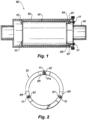
Fig. 1 is a cross-sectional view of an embodiment of an assembly in accordance with this disclosure; and -
Fig. 2 is a plan view of an embodiment of a diode holder of the embodiment ofFig. 1 . - Reference will now be made to the drawings wherein like reference numerals identify similar structural features or aspects of the subject disclosure. For purposes of explanation and illustration, and not limitation, an illustrative view of an embodiment of an assembly in accordance with the disclosure is shown in
Fig. 1 and is designated generally byreference character 100. Other embodiments and/or aspects of this disclosure are shown inFig. 2 . Certain embodiments described herein can be used to reduce stress at the interface of a diode holder and rotor housing in a rotating diode rotor assembly a generator, for example. - In accordance with at least one aspect of this disclosure, referring to
Figs. 1 and 2 , agenerator rotor assembly 100 can include adiode holder 101 configured to hold one or more diodes (for a rotating diode assembly, not shown). Thediode holder 101 can be formed of a first material having a first coefficient of thermal expansion (CTE). - The
assembly 100 can include a rotor housing 103 (e.g., connected to and/or part of a rotor 105) configured to hold thediode holder 101 within the rotor housing 103 (e.g., enclosed therein or otherwise). Therotor housing 103 can be formed of a second material having a second CTE. The second CTE is different than the first CTE. - The
assembly 100 can include one or moreCTE compensation spacers 107 interfacing thediode holder 101 to therotor housing 103 such that thediode holder 101 and therotor housing 103 are connected via the one or moreCTE compensation spacers 107. The one or moreCTE compensation spacers 107 can be configured to have a third CTE different than the first CTE and the second CTE to compensate for relative length change between thediode holder 101 and therotor housing 103 to prevent and/or reduce temperature induced stress growth at the interface (e.g., the connection point) of thediode holder 101 and therotor housing 103. - In certain embodiments, the
CTE compensation spacer 107 can include a negative CTE such that the CTE compensation spacer shrinks with increasing temperature. In this regard, if the first CTE and the second CTE are positive but different, the negativeCTE compensation spacer 107 can become smaller to account for relative movement between therotor housing 103 and thediode holder 101. It is contemplated that theCTE compensation spacer 107 can be a positive CTE and the first CTE and second CTE can be negative CTE to provide a similar effect. - The thickness of each
CTE compensation spacer 107 can be selected to provide the change in shape needed to account for expansion ofdiode holder 101 relative to therotor housing 103. Any suitable thickness and/or geometry to provide any suitable compensation for any suitable application is contemplated herein. - In certain embodiments, the
diode holder 101 can include one or more mount tabs 109 (e.g., three symmetrically/evenly spaced arcuate sections as shown) extending therefrom. The one ormore mount tabs 109 can extend axially from the diode holder 101 (e.g., as shown inFig. 1 ). EachCTE compensation spacer 107 can be mounted (e.g., attached to) to and/or trapped within arespective mount tab 109. Thespacer 107 can be held to thediode holder 101 and/or thetabs 109 thereof in any suitable manner (e.g., mechanically, with adhesive, via compression, etc.). - In certain embodiments, the
mounting tabs 109 can define ahole 111a (e.g., drilled into the tabs 109) that can be configured to receive aCTE compensation spacer 107 and/or to allow access to an otherwise insertedCTE compensation spacer 107 for a fastener to attach to. In certain embodiments, themounting tabs 109 can be configured such that the respectiveCTE compensation spacer 107 can be axially trapped within eachmounting tab 109. - The one or more
CTE compensation spacers 107 can be configured to abut a threaded fastener 111 (e.g., a screw). For example, theassembly 100 can include one or more threadedfasteners 111 disposed in therotor housing 103 abutting the one or moreCTE compensation spacers 107, thereby retaining thediode holder 101 within rotor housing 103 (e.g., using compression as shown). The one or more threadedfasteners 111 can be axially threaded through therotor housing 103 to contact eachCTE compensation spacer 107 held within eachmount tab 109, e.g., as shown. While threaded fasteners 111 (e.g., set screws) are shown and described, any suitable fastener arrangement or other attachment between thediode holder 101 and therotor housing 103 using the one or moreCTE compensation spacers 107 to provide CTE compensation is contemplated herein. Any suitable structure utilizing a compensating CTE configured to reduce stress at the interface of two different structures is contemplated herein. - In certain embodiments, the
diode holder 101 can be made of aluminum. In certain embodiments, therotor housing 103 can be made of stainless steel. In certain embodiments, the one or more threadedfasteners 111 can be made of the same material as the rotor housing 103 (e.g., stainless steel). - In certain embodiments, the
diode housing 101 can be axially fixed within therotor housing 103. For example, as shown, thediode housing 101 can be axially stopped bybackstops 113 in therotor housing 103. The threadedfasteners 111 can ultimately press thediode holder 101 against thebackstops 113 to axially fix thediode holder 101 within therotor housing 103. The threadedfasteners 111 can be used to provide a preload to thediode housing 101. The one or moreCTE compensation spacers 107 can thus prevent additional loading by shrinking between the threadedfastener 111 and thetabs 109. Any other suitable arrangement to fix thediode housing 101 axially is contemplated herein. - In accordance with at least one aspect of this disclosure, a generator (not shown) can include a generator rotor assembly. The generator rotor assembly can be or include any suitable embodiment of an assembly as disclosed herein, e.g.,
assembly 100 as described above. - In accordance with at least one aspect of this disclosure, a method can include interfacing a diode holder to a rotor housing using a negative CTE compensation spacer to reduce or eliminate temperature induced stress caused by relative growth between the diode holder and the rotor housing. In certain embodiments, the method can further include forming a hole in a mounting tab of the diode holder, trapping the negative CTE compensation spacer in the hole, and abutting a fastener attached to the rotor housing to the negative CTE compensation spacer.
- In certain embodiments, e.g., where the fasteners and rotor are steel and the diode holder is aluminum, there will be a CTE mismatch and the aluminum would grow axially relative to the steel in use. Embodiments can include tabs machined in the diode holder. Set screws can be fixed to the rotor and made to contact the tabs, and the set screws can be adjusted to control the preload between the diode holder and the rotor housing (e.g., which acts on the tabs).
- Embodiments can include one spacer per set screw that has negative CTE which can reduce net thermal expansion of the assembly. Certain embodiments can have a single spacer for all screws, or any other suitable number of spacers. In certain embodiments, each spacer can be bonded to the tabs and the steel screws can press against to each spacer.
- Embodiments can include drilling a hole in each tab. The size of the hole, and thus the compensation spacer, may be limited by the inner diameter and the outer diameter of the diode holder. Each spacer can be inserted into a respective tab, then be bonded to the bottom face of the drilled hole in the tab. The thickness of each CTE compensation spacer can be selected to provide the change in length needed to account for expansion of diode holder relative to the rotor housing and/or set screws.
- Embodiments can provide axial preload control using negative CTE compensation spacers in generator rotors, for example. As disclosed above, the coefficient of thermal expansion (CTE) of a diode holder which can be made of aluminum can be higher than that for the rotor and/or set screws that attach the rotor to the diode holder, and which can be made of steel. With increase in temperature, the expansion of the aluminum is larger than that for steel and hence can create a considerable increase in axial preload without compensation. By housing certain compensation spacers/pads of negative CTE (e.g., ALLVAR alloy) in the diode holder at the contact location, the extent of preload increase can be considerably reduced or eliminated. A desired pad thickness can be determined from the CTE differences of the materials involved and relevant length for thermal growth to produce reduced or eliminated preload increase.
- Embodiments can provide a reduction in design preload due to thermal cycling which can instead be controlled and eliminated. Permanent deformation at the contact locations in diode holders can be eliminated.
- Those having ordinary skill in the art understand that any numerical values disclosed herein can be exact values or can be values within a range. Further, any terms of approximation (e.g., "about", "approximately", "around") used in this disclosure can mean the stated value within a range. For example, in certain embodiments, the range can be within (plus or minus) 20%, or within 10%, or within 5%, or within 2%, or within any other suitable percentage or number as appreciated by those having ordinary skill in the art (e.g., for known tolerance limits or error ranges).
- The articles "a", "an", and "the" as used herein and in the appended claims are used herein to refer to one or to more than one (i.e., to at least one) of the grammatical object of the article unless the context clearly indicates otherwise. By way of example, "an element" means one element or more than one element.
- The phrase "and/or," as used herein in the specification and in the claims, should be understood to mean "either or both" of the elements so conjoined, i.e., elements that are conjunctively present in some cases and disjunctively present in other cases. Multiple elements listed with "and/or" should be construed in the same fashion, i.e., "one or more" of the elements so conjoined. Other elements may optionally be present other than the elements specifically identified by the "and/or" clause, whether related or unrelated to those elements specifically identified. Thus, as a non-limiting example, a reference to "A and/or B", when used in conjunction with open-ended language such as "comprising" can refer, in one embodiment, to A only (optionally including elements other than B); in another embodiment, to B only (optionally including elements other than A); in yet another embodiment, to both A and B (optionally including other elements); etc.
- As used herein in the specification and in the claims, "or" should be understood to have the same meaning as "and/or" as defined above. For example, when separating items in a list, "or" or "and/or" shall be interpreted as being inclusive, i.e., the inclusion of at least one, but also including more than one, of a number or list of elements, and, optionally, additional unlisted items. Only terms clearly indicated to the contrary, such as "only one of' or "exactly one of," or, when used in the claims, "consisting of," will refer to the inclusion of exactly one element of a number or list of elements. In general, the term "or" as used herein shall only be interpreted as indicating exclusive alternatives (i.e., "one or the other but not both") when preceded by terms of exclusivity, such as "either," "one of," "only one of," or "exactly one of."
- Any suitable combination(s) of any disclosed embodiments and/or any suitable portion(s) thereof are contemplated herein as appreciated by those having ordinary skill in the art in view of this disclosure.
- The embodiments of the present disclosure, as described above and shown in the drawings, provide for improvement in the art to which they pertain. While the subject disclosure includes reference to certain embodiments, those skilled in the art will readily appreciate that changes and/or modifications may be made thereto without departing from the scope of the invention as defined by the claims.
Claims (13)
- A generator rotor assembly, comprising:a diode holder (101) configured to hold one or more diodes, wherein the diode holder is formed of a first material having a first coefficient of thermal expansion, CTE;a rotor housing (103) configured to hold the diode holder within the rotor housing, wherein the rotor housing is formed of a second material having a second CTE, wherein the second CTE is different than the first CTE; andone or more CTE compensation spacers (107) interfacing the diode holder to the rotor housing such that the diode holder and the rotor housing are connected via the one or more CTE compensation spacers, wherein the one or more CTE compensation spacers are configured to have a third CTE different than the first CTE and the second CTE to compensate for relative length change between the diode holder and the rotor housing to prevent and/or reduce temperature induced stress growth at the interface of the diode holder and the rotor housing.
- The assembly of claim 1, wherein the CTE compensation spacer includes a negative CTE such that the CTE compensation spacer shrinks with increasing temperature.
- The assembly of claim 1 or 2, wherein the diode holder (101) includes one or more mount tabs (109) extending therefrom.
- The assembly of claim 3, wherein the one or more mount tabs extend axially from the diode holder.
- The assembly of claim 4, wherein each CTE compensation spacer (107) is mounted to and/or trapped within a respective mount tab (109).
- The assembly of claim 5, wherein the one or more CTE compensation spacers are configured to abut a threaded fastener (111).
- The assembly of claim 5, further comprising one or more threaded fasteners (111) attaching the rotor housing (103) to the one or more CTE compensation spacers (107), thereby connecting the rotor housing to the diode holder.
- The assembly of claim 7, wherein the diode holder (101) is made of aluminum.
- The assembly of claim 8, wherein the rotor housing (103) is made of stainless steel, wherein the one or more threaded fasteners (111) are made of the same material type as the rotor housing.
- The assembly of any preceding claim, wherein the diode holder (101) is axially fixed within the rotor housing (103).
- A generator, comprising:
a generator rotor assembly as claimed in any preceding claim. - A method, comprising:
interfacing a diode holder (101) to a rotor housing (103) using a negative CTE compensation spacer (107) to reduce or eliminate temperature induced stress caused by relative growth between the diode holder and the rotor housing. - The method of claim 12, further comprising:forming a hole (111a) in a mounting tab (109) of the diode holder;trapping the negative CTE compensation spacer into the hole; andabutting a fastener (111) attached to the rotor housing to the negative CTE compensation spacer.
Applications Claiming Priority (1)
| Application Number | Priority Date | Filing Date | Title |
|---|---|---|---|
| US17/740,818 US11831207B1 (en) | 2022-05-10 | 2022-05-10 | Generator rotor assemblies |
Publications (1)
| Publication Number | Publication Date |
|---|---|
| EP4277091A1 true EP4277091A1 (en) | 2023-11-15 |
Family
ID=86331197
Family Applications (1)
| Application Number | Title | Priority Date | Filing Date |
|---|---|---|---|
| EP23172602.7A Pending EP4277091A1 (en) | 2022-05-10 | 2023-05-10 | Generator rotor assemblies |
Country Status (2)
| Country | Link |
|---|---|
| US (1) | US11831207B1 (en) |
| EP (1) | EP4277091A1 (en) |
Citations (6)
| Publication number | Priority date | Publication date | Assignee | Title |
|---|---|---|---|---|
| US3412271A (en) * | 1965-12-08 | 1968-11-19 | Westinghouse Electric Corp | Brushless type alternating current machine |
| US4745315A (en) * | 1983-12-15 | 1988-05-17 | General Electric Company | Brushless exciter with zero-gravity rectifier assembly |
| US5773903A (en) * | 1996-12-20 | 1998-06-30 | Sundstrand Corporation | Rotating rectifier assembly |
| US20060284499A1 (en) * | 2005-06-17 | 2006-12-21 | Hamilton Sundstrand Corporation | Rotating rectifier module |
| EP2940840B1 (en) * | 2014-04-10 | 2017-07-12 | GE Aviation Systems LLC | Rotating rectifier assembly for electric machine |
| US20200149577A1 (en) * | 2013-06-14 | 2020-05-14 | James Alan Monroe | Thermally stabilized fastener system and method |
Family Cites Families (7)
| Publication number | Priority date | Publication date | Assignee | Title |
|---|---|---|---|---|
| FR2087126A5 (en) * | 1970-05-05 | 1971-12-31 | Brissonneau & Lotz | |
| US4570094A (en) | 1984-01-23 | 1986-02-11 | Sundstrand Corporation | Rotating rectifier assembly |
| JPH0338098A (en) * | 1989-07-04 | 1991-02-19 | Toyota Motor Corp | Resin sealing of electronic component module |
| GB9000787D0 (en) | 1990-01-13 | 1990-03-14 | Lucas Ind Plc | Rotating rectifier assembly |
| WO2006028981A2 (en) * | 2004-09-01 | 2006-03-16 | Remy International, Inc. | Electronic package for electrical machine |
| JP4578546B2 (en) * | 2008-07-09 | 2010-11-10 | 三菱電機株式会社 | AC generator |
| US9325388B2 (en) * | 2012-06-21 | 2016-04-26 | Siemens Energy, Inc. | Wireless telemetry system including an induction power system |
-
2022
- 2022-05-10 US US17/740,818 patent/US11831207B1/en active Active
-
2023
- 2023-05-10 EP EP23172602.7A patent/EP4277091A1/en active Pending
Patent Citations (6)
| Publication number | Priority date | Publication date | Assignee | Title |
|---|---|---|---|---|
| US3412271A (en) * | 1965-12-08 | 1968-11-19 | Westinghouse Electric Corp | Brushless type alternating current machine |
| US4745315A (en) * | 1983-12-15 | 1988-05-17 | General Electric Company | Brushless exciter with zero-gravity rectifier assembly |
| US5773903A (en) * | 1996-12-20 | 1998-06-30 | Sundstrand Corporation | Rotating rectifier assembly |
| US20060284499A1 (en) * | 2005-06-17 | 2006-12-21 | Hamilton Sundstrand Corporation | Rotating rectifier module |
| US20200149577A1 (en) * | 2013-06-14 | 2020-05-14 | James Alan Monroe | Thermally stabilized fastener system and method |
| EP2940840B1 (en) * | 2014-04-10 | 2017-07-12 | GE Aviation Systems LLC | Rotating rectifier assembly for electric machine |
Non-Patent Citations (2)
| Title |
|---|
| ALLVAR UNIVERSITY: "Creating a Tailored Thermal Expansion Part 3 -Tailoring Thermal Expansion to Achieve Zero Expansion with ALLVAR Alloys - ALLVAR Alloys", LEARN ABOUT CTE, ULTRA-STABLE STRUTS, 27 April 2021 (2021-04-27), pages 1 - 6, XP093333159, Retrieved from the Internet <URL:https://web.archive.org/web/20210728072213/https://allvaralloys.com/aiovg_videos/achieving-zero-thermal-expansion-with-allvar-alloys/> [retrieved on 20251105] * |
| SAE INTERNATIONAL: "AIR1754B Washer, Thermal Compensation, Metric Series", GENERAL STANDARDS FOR AEROSPACE AND PROPULSION SYSTEMS, 18 February 2019 (2019-02-18), pages 1 - 5, XP093332922, Retrieved from the Internet <URL:https://saemobilus.sae.org/standards/air1754b-washer-thermal-compensating-metric-series#view> [retrieved on 20251105], DOI: 10.4271/AIR1754B * |
Also Published As
| Publication number | Publication date |
|---|---|
| US20230369947A1 (en) | 2023-11-16 |
| US11831207B1 (en) | 2023-11-28 |
Similar Documents
| Publication | Publication Date | Title |
|---|---|---|
| US4643647A (en) | Rotor aerofoil blade containment | |
| DE69509137T2 (en) | VIBRATION DAMPING TAPE FOR A TURBO MACHINE SHOVEL | |
| EP0670796B1 (en) | Rotor blade balance weight assembly | |
| EP1923578A2 (en) | CMC fastening system | |
| EP1235010A3 (en) | Repositionable brush seal for turbomachinery | |
| EP2871331B1 (en) | Method for tight control of bolt holes in fan assembly | |
| US4397609A (en) | Bandage for radially stressing the segments of a compressor rotor for a turbine | |
| US4361953A (en) | Method of securing end shields to the stator assembly of a dynamoelectric machine | |
| EP3327308A1 (en) | Bridged clip retainer for brake system | |
| EP3088684B1 (en) | Gas turbine engine comprising a stator damper and corresponding method of making | |
| CA1125830A (en) | System and method of securing end shields to the stator assembly of a dynamoelectric machine | |
| EP2418759A2 (en) | Rotating electric machine and method of manufacturing rotating electric machine | |
| EP0289966A2 (en) | A process for balancing a crankshaft, and a crankshaft balanced thereby | |
| CA2896508A1 (en) | Non-integral fan blade platform | |
| US11831207B1 (en) | Generator rotor assemblies | |
| US5073039A (en) | Bearing assembly with thermal compensation | |
| US5036674A (en) | Accumulator mounting method and apparatus | |
| US20170130790A1 (en) | Low radial profile brake disk insert retainer | |
| US4664600A (en) | Rotor aerofoil blade containment | |
| JP2015519861A (en) | Magnet holding on the rotor | |
| US4086426A (en) | Stress relieved printed wiring board | |
| WO2023212454A2 (en) | Resilient fastener system and resilient fastener insert | |
| US20210404531A1 (en) | Shock absorption bracket | |
| EP3107194A1 (en) | Supporting device and method for supporting winding coils in a wind turbine generator | |
| WO2017100612A1 (en) | Bearing assembly for electrical generator |
Legal Events
| Date | Code | Title | Description |
|---|---|---|---|
| PUAI | Public reference made under article 153(3) epc to a published international application that has entered the european phase |
Free format text: ORIGINAL CODE: 0009012 |
|
| STAA | Information on the status of an ep patent application or granted ep patent |
Free format text: STATUS: THE APPLICATION HAS BEEN PUBLISHED |
|
| AK | Designated contracting states |
Kind code of ref document: A1 Designated state(s): AL AT BE BG CH CY CZ DE DK EE ES FI FR GB GR HR HU IE IS IT LI LT LU LV MC ME MK MT NL NO PL PT RO RS SE SI SK SM TR |
|
| STAA | Information on the status of an ep patent application or granted ep patent |
Free format text: STATUS: REQUEST FOR EXAMINATION WAS MADE |
|
| 17P | Request for examination filed |
Effective date: 20240514 |
|
| RBV | Designated contracting states (corrected) |
Designated state(s): AL AT BE BG CH CY CZ DE DK EE ES FI FR GB GR HR HU IE IS IT LI LT LU LV MC ME MK MT NL NO PL PT RO RS SE SI SK SM TR |
|
| STAA | Information on the status of an ep patent application or granted ep patent |
Free format text: STATUS: EXAMINATION IS IN PROGRESS |
|
| 17Q | First examination report despatched |
Effective date: 20251113 |