EP4276985A1 - Battery - Google Patents
Battery Download PDFInfo
- Publication number
- EP4276985A1 EP4276985A1 EP23168495.2A EP23168495A EP4276985A1 EP 4276985 A1 EP4276985 A1 EP 4276985A1 EP 23168495 A EP23168495 A EP 23168495A EP 4276985 A1 EP4276985 A1 EP 4276985A1
- Authority
- EP
- European Patent Office
- Prior art keywords
- electrolytic solution
- battery
- injection hole
- sealing member
- projection
- Prior art date
- Legal status (The legal status is an assumption and is not a legal conclusion. Google has not performed a legal analysis and makes no representation as to the accuracy of the status listed.)
- Granted
Links
Images


Classifications
-
- H—ELECTRICITY
- H01—ELECTRIC ELEMENTS
- H01M—PROCESSES OR MEANS, e.g. BATTERIES, FOR THE DIRECT CONVERSION OF CHEMICAL ENERGY INTO ELECTRICAL ENERGY
- H01M50/00—Constructional details or processes of manufacture of the non-active parts of electrochemical cells other than fuel cells, e.g. hybrid cells
- H01M50/10—Primary casings; Jackets or wrappings
- H01M50/102—Primary casings; Jackets or wrappings characterised by their shape or physical structure
- H01M50/103—Primary casings; Jackets or wrappings characterised by their shape or physical structure prismatic or rectangular
-
- H—ELECTRICITY
- H01—ELECTRIC ELEMENTS
- H01M—PROCESSES OR MEANS, e.g. BATTERIES, FOR THE DIRECT CONVERSION OF CHEMICAL ENERGY INTO ELECTRICAL ENERGY
- H01M50/00—Constructional details or processes of manufacture of the non-active parts of electrochemical cells other than fuel cells, e.g. hybrid cells
- H01M50/10—Primary casings; Jackets or wrappings
- H01M50/147—Lids or covers
- H01M50/148—Lids or covers characterised by their shape
- H01M50/15—Lids or covers characterised by their shape for prismatic or rectangular cells
-
- H—ELECTRICITY
- H01—ELECTRIC ELEMENTS
- H01M—PROCESSES OR MEANS, e.g. BATTERIES, FOR THE DIRECT CONVERSION OF CHEMICAL ENERGY INTO ELECTRICAL ENERGY
- H01M50/00—Constructional details or processes of manufacture of the non-active parts of electrochemical cells other than fuel cells, e.g. hybrid cells
- H01M50/10—Primary casings; Jackets or wrappings
- H01M50/183—Sealing members
- H01M50/184—Sealing members characterised by their shape or structure
-
- H—ELECTRICITY
- H01—ELECTRIC ELEMENTS
- H01M—PROCESSES OR MEANS, e.g. BATTERIES, FOR THE DIRECT CONVERSION OF CHEMICAL ENERGY INTO ELECTRICAL ENERGY
- H01M50/00—Constructional details or processes of manufacture of the non-active parts of electrochemical cells other than fuel cells, e.g. hybrid cells
- H01M50/10—Primary casings; Jackets or wrappings
- H01M50/183—Sealing members
- H01M50/186—Sealing members characterised by the disposition of the sealing members
-
- H—ELECTRICITY
- H01—ELECTRIC ELEMENTS
- H01M—PROCESSES OR MEANS, e.g. BATTERIES, FOR THE DIRECT CONVERSION OF CHEMICAL ENERGY INTO ELECTRICAL ENERGY
- H01M50/00—Constructional details or processes of manufacture of the non-active parts of electrochemical cells other than fuel cells, e.g. hybrid cells
- H01M50/60—Arrangements or processes for filling or topping-up with liquids; Arrangements or processes for draining liquids from casings
- H01M50/609—Arrangements or processes for filling with liquid, e.g. electrolytes
- H01M50/627—Filling ports
-
- H—ELECTRICITY
- H01—ELECTRIC ELEMENTS
- H01M—PROCESSES OR MEANS, e.g. BATTERIES, FOR THE DIRECT CONVERSION OF CHEMICAL ENERGY INTO ELECTRICAL ENERGY
- H01M50/00—Constructional details or processes of manufacture of the non-active parts of electrochemical cells other than fuel cells, e.g. hybrid cells
- H01M50/60—Arrangements or processes for filling or topping-up with liquids; Arrangements or processes for draining liquids from casings
- H01M50/609—Arrangements or processes for filling with liquid, e.g. electrolytes
- H01M50/627—Filling ports
- H01M50/636—Closing or sealing filling ports, e.g. using lids
-
- Y—GENERAL TAGGING OF NEW TECHNOLOGICAL DEVELOPMENTS; GENERAL TAGGING OF CROSS-SECTIONAL TECHNOLOGIES SPANNING OVER SEVERAL SECTIONS OF THE IPC; TECHNICAL SUBJECTS COVERED BY FORMER USPC CROSS-REFERENCE ART COLLECTIONS [XRACs] AND DIGESTS
- Y02—TECHNOLOGIES OR APPLICATIONS FOR MITIGATION OR ADAPTATION AGAINST CLIMATE CHANGE
- Y02E—REDUCTION OF GREENHOUSE GAS [GHG] EMISSIONS, RELATED TO ENERGY GENERATION, TRANSMISSION OR DISTRIBUTION
- Y02E60/00—Enabling technologies; Technologies with a potential or indirect contribution to GHG emissions mitigation
- Y02E60/10—Energy storage using batteries
Definitions
- the present application relates to batteries.
- a battery known in the art includes: an exterior body including an opening; a closing plate including an electrolytic solution injection hole and closing the opening of the exterior body; a sealing member sealing the electrolytic solution injection hole; an electrode body housed in the exterior body; and an electrolytic solution stored in the exterior body.
- a technique related to such a battery is disclosed in, for example, JP 2017-135025 A .
- JP 2017-135025 A involves: housing an electrode body in an exterior body; closing an opening of the exterior body with a closing plate; injecting an electrolytic solution into a battery case through an electrolytic solution injection hole of the closing plate; and welding a sealing member to a portion of the battery case (or more specifically, a portion of the closing plate) defining a peripheral edge of the electrolytic solution injection hole, such that a battery is sealed airtightly (or closed hermetically).
- the electrolytic solution may volatilize, which may fill the inside of the battery with gas.
- an increase in internal pressure of the battery may warp a closing plate, causing deformation of a portion of a battery case (or more specifically, a portion of the closing plate) in the vicinity of an electrolytic solution injection hole. This may result in damage to or breakage of a portion of the battery case (or more specifically, a portion of the closing plate) to which a sealing member is welded.
- a high-capacity or large-size battery to be used in particular, as a power source (such as a vehicle driving power source) includes a closing plate large in size and/or contains a large amount of electrolytic solution and thus has a pronounced tendency to encounter the problems mentioned above.
- embodiments of the present application provide batteries each of which prevents or reduces deformation of a portion of a battery case in the vicinity of an electrolytic solution injection hole and thus resists damage to or breakage of a connection between the battery case and a sealing member.
- An embodiment of the present application provides a battery including: an electrode body including a positive electrode and a negative electrode; an electrolytic solution; a battery case housing the electrode body, storing the electrolytic solution, and including an electrolytic solution injection hole; and a sealing member connected to a portion of the battery case defining a peripheral edge of the electrolytic solution injection hole, such that the electrolytic solution injection hole is sealed with the sealing member.
- a surface of the battery case facing the electrode body includes a protrusion located around the electrolytic solution injection hole and protruding toward the electrode body.
- the embodiment of the present application involves providing the protrusion, which protrudes toward the electrode body, on the surface of the battery case facing the electrode body.
- This embodiment is thus able to increase the rigidity of a portion of the battery case in the vicinity of the electrolytic solution injection hole. Accordingly, this embodiment is able to prevent or reduce deformation of the portion of the battery case in the vicinity of the electrolytic solution injection hole during an increase in internal pressure more effectively than when no protrusion is provided. Consequently, this embodiment is able to prevent damage to or breakage of a connection between the battery case and the sealing member, resulting in increased reliability of the connection.
- battery refers to any of various electricity storage devices from which electric energy is derivable, and is a concept encompassing primary batteries and secondary batteries.
- secondary battery refers to any of various electricity storage devices that are repeatedly chargeable and dischargeable, and is a concept encompassing storage batteries (or chemical batteries), such as lithium ion secondary batteries and nickel-metal hydride batteries, and capacitors (or physical batteries), such as electric double layer capacitors.
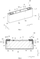
- FIG. 1 is a perspective view of a battery 100.
- FIG. 2 is a schematic longitudinal cross-sectional view of the battery 100 taken along the line II-II in FIG. 1 .
- the reference signs L, R, F, Rr, U, and D in the drawings respectively represent left, right, front, rear, up, and down.
- a direction along the short sides of the battery 100 in a plan view will hereinafter be referred to as a "short-side direction X".
- a direction along the long sides of the battery 100 in the plan view and perpendicular or substantially perpendicular to the short-side direction X will hereinafter be referred to as a "long-side direction Y”.
- a direction along the height of the battery 100 will hereinafter be referred to as an "up-down direction Z".
- the battery 100 includes a battery case 10, an electrode body assembly 20, a positive electrode terminal 30, a negative electrode terminal 40, a positive electrode collector 50, a negative electrode collector 60, and an electrolytic solution (not illustrated).
- the battery 100 is preferably a secondary battery.
- the battery 100 is more preferably a nonaqueous electrolytic solution secondary battery.
- the battery 100 is a lithium ion secondary battery.
- the battery case 10 is a casing housing the electrode body assembly 20 and storing the electrolytic solution.
- the battery case 10 in the present embodiment has a flat cuboidal outer shape (or rectangular outer shape) with a bottom.
- the battery case 10 preferably has a rectangular outer shape.
- the battery case 10 may be made of any material known in the art or may be made of any other suitable material.
- the battery case 10 is preferably made of metal.
- the battery case 10 is more preferably made of, for example, aluminum, an aluminum alloy, iron, or an iron alloy.
- a battery case preferably includes: an exterior body including an opening; and a closing plate (or lid) closing the opening.
- the battery case 10 in the present embodiment includes: an exterior body 12 including an opening 12h; and a closing plate (or lid) 14 closing the opening 12h.
- the exterior body 12 includes: a bottom wall 12a; a pair of long side walls 12b extending from the bottom wall 12a and facing each other; and a pair of short side walls 12c extending from the bottom wall 12a and facing each other.
- the bottom wall 12a has a substantially rectangular shape.
- the bottom wall 12a faces the opening 12h.
- the long side walls 12b are larger in area than the short side walls 12c.
- the closing plate 14 is attached to the exterior body 12 such that the opening 12h of the exterior body 12 is closed with the closing plate 14.
- the closing plate 14 faces the bottom wall 12a of the exterior body 12.
- the closing plate 14 has a substantially rectangular shape in the plan view.
- the closing plate 14 is connected (or preferably welded) to a portion of the exterior body 12 defining a peripheral edge of the opening 12h and is thus integral with the exterior body 12. Accordingly, the battery case 10 is sealed airtightly (or closed hermetically).
- the closing plate 14 is provided with: an electrolytic solution injection hole 15; a discharge valve 17; a first through hole 18 through which the positive electrode terminal 30 is inserted; and a second through hole 19 through which the negative electrode terminal 40 is inserted.
- the discharge valve 17 breaks such that gas inside the battery case 10 is discharged out of the battery case 10.
- the through holes 18 and 19 each pass through the closing plate 14 in the up-down direction Z.
- the through hole 18 has an inside diameter that allows insertion of the positive electrode terminal 30 therethrough before the positive electrode terminal 30 is attached to the closing plate 14 (i.e., before the positive electrode terminal 30 is subjected to swaging).
- the through hole 19 has an inside diameter that allows insertion of the negative electrode terminal 40 therethrough before the negative electrode terminal 40 is attached to the closing plate 14 (i.e., before the negative electrode terminal 40 is subjected to swaging).
- the electrolytic solution injection hole 15 is preferably defined in the closing plate 14.
- a surface of the battery case 10 provided with the electrolytic solution injection hole 15 may have any suitable length in the short-side direction X.
- the surface of the battery case 10 (which is provided with the electrolytic solution injection hole 15) preferably has a length of 20 mm or more in the short-side direction X and more preferably has a length of 25 mm or more in the short-side direction X.
- FIG. 3 is a schematic longitudinal cross-sectional view of a portion of the battery 100 in the vicinity of the electrolytic solution injection hole 15.
- FIG. 4 is a partially cutaway perspective view of the battery 100, schematically illustrating the portion of the battery 100 in the vicinity of the electrolytic solution injection hole 15.
- the electrolytic solution injection hole 15 is sealed with a sealing member (or sealing cap) 16.
- the sealing member 16 is preferably made of metal.
- the sealing member 16 is more preferably made of, for example, aluminum or an aluminum alloy.
- the electrolytic solution injection hole 15 and the sealing member 16 each have a substantially circular outer shape in the plan view.
- the sealing member 16 preferably has a circular outer shape.
- the sealing member 16 may have any other suitable shape other than a circular shape. As illustrated in FIG. 3 , the sealing member 16 has an outside diameter R2 larger than the outside diameter of the electrolytic solution injection hole 15. As illustrated in FIGS. 3 and 4 , the electrolytic solution injection hole 15 in the present embodiment is sealed by connecting (e.g., welding) the sealing member 16 to a portion of the closing plate 14 defining a peripheral edge of the electrolytic solution injection hole 15. The sealing member 16 may be connected to the portion of the closing plate 14 (which defines the peripheral edge of the electrolytic solution injection hole 15) by any method known in the art, such as laser welding.
- the closing plate 14 of the battery case 10 includes a protrusion 14a, a recess 14b, a first projection 14c1, and a second projection 14c2.
- the recess 14b includes a first recess 14b 1, a second recess 14b2, and a third recess 14b3.
- the third recess 14b3 is an example of a fluid retention recess.
- the protrusion 14a is provided on a surface of the battery case 10 facing the electrode body assembly 20 (or more specifically, a surface of the closing plate 14 facing the electrode body assembly 20). In other words, the protrusion 14a is provided on an inner surface of the battery case 10 (i.e., a lower surface 14d of the closing plate 14 in FIG. 3 ). The protrusion 14a protrudes toward the electrode body assembly 20 (i.e., downward in FIG. 3 ) from a base portion of the closing plate 14 (which is a flat portion of the closing plate 14). Providing the protrusion 14a increases the rigidity of a portion of the closing plate 14 in the vicinity of the electrolytic solution injection hole 15.
- the present embodiment is thus able to prevent or reduce deformation of the portion of the closing plate 14 in the vicinity of the electrolytic solution injection hole 15. Accordingly, the present embodiment is able to prevent damage to or breakage of a connection W between the closing plate 14 and the sealing member 16, resulting in increased reliability of the connection W.
- the protrusion 14a has a substantially ring-like outer shape (i.e., a substantially annular outer shape) in the plan view. As illustrated in FIG. 3 , the protrusion 14a has an outside diameter R1 larger than the outside diameter of the electrolytic solution injection hole 15. The protrusion 14a is disposed around the electrolytic solution injection hole 15 such that the protrusion 14a surrounds the electrolytic solution injection hole 15. The electrolytic solution injection hole 15 passes through the protrusion 14a in the up-down direction Z. In the present embodiment, the outside diameter R1 of the protrusion 14a is larger than the outside diameter R2 of the sealing member 16.
- the protrusion 14a may have any suitable outside diameter R1, the outside diameter R1 of the protrusion 14a is preferably larger than the outside diameter R2 of the sealing member 16. The present embodiment is thus able to more effectively prevent or reduce deformation of the portion of the closing plate 14 in the vicinity of the electrolytic solution injection hole 15.
- the outside diameter R1 of the protrusion 14a may be equal to or smaller than the outside diameter R2 of the sealing member 16.
- the ratio of T2 to T1 is preferably 0.6 or more, and more preferably 0.8 or more (where T1 represents a thickness of the base portion or flat portion of the closing plate 14, and T2 represents a thickness of the protrusion 14a).
- the ratio (T2/T1) may be about 2 or less (e.g., 1 or less).
- the thickness T2 of the protrusion 14a is preferably 1 mm or more, and more preferably 1.5 mm or more. The present embodiment is thus able to more effectively prevent or reduce deformation of the portion of the closing plate 14 in the vicinity of the electrolytic solution injection hole 15, achieving the effects of the techniques disclosed herein at higher level.
- the recess 14b is provided in an outer surface of the battery case 10 (or more specifically, an outer surface of the closing plate 14). In other words, the recess 14b is provided in an upper surface 14u of the closing plate 14 in FIG. 3 . As is clear from FIGS. 3 and 4 , the recess 14b is larger in outside diameter than the electrolytic solution injection hole 15 in the plan view. The recess 14b is disposed around the electrolytic solution injection hole 15 such that the recess 14b surrounds the electrolytic solution injection hole 15. In the plan view, the outside diameter of the recess 14b in the present embodiment is larger than the outside diameter R1 of the protrusion 14a.
- the sealing member 16 is disposed in the recess 14b such that the second recess 14b2 and the third recess 14b3 are covered with the sealing member 16. Disposing the sealing member 16 in the recess 14b makes it possible to reduce the length of protrusion of the sealing member 16 in the up-down direction Z from an upper surface of the battery case 10. The present embodiment thus makes it unlikely that the connection W between the closing plate 14 and the sealing member 16 will protrude from the upper surface of the battery case 10 (or more specifically, the upper surface 14u of the closing plate 14). Accordingly, the present embodiment is able to more effectively prevent damage to or breakage of the connection W caused by interference of the connection W with other member(s). Alternatively, the sealing member 16 may be disposed in or on a portion of the closing plate 14 other than the recess 14b.
- the first projection 14c1 is disposed inside the recess 14b. As is clear from FIGS. 3 and 4 , the first projection 14c1 has a substantially ring-like outer shape (i.e., a substantially annular outer shape) in the plan view. The substantially ring-like shape of the first projection 14c1 may be partially cut away. The first projection 14c1 is larger in outside diameter than the electrolytic solution injection hole 15. The first projection 14c1 is disposed around the electrolytic solution injection hole 15 such that the first projection 14c1 surrounds the electrolytic solution injection hole 15. As illustrated in FIG. 3 , the outside diameter of the first projection 14c1 in the present embodiment is smaller than the outside diameter R1 of the protrusion 14a.
- the first projection 14c1 has an inside diameter substantially equal to the outside diameter R2 of the sealing member 16.
- An inner peripheral wall surface of the first projection 14c1 i.e., a wall surface of the first projection 14c1 located toward the electrolytic solution injection hole 15
- the sealing member 16 is fitted to an inner portion of the first projection 14c1.
- the first projection 14c1 also functions as a guide indicating a position where the sealing member 16 is to be fitted to the closing plate 14.
- the first projection 14c1 includes an inner edge flush with an upper surface 16u of the sealing member 16.
- the first projection 14c1 is connected to an outer peripheral edge of the sealing member 16.
- the first projection 14c1 is preferably welded to the outer peripheral edge of the sealing member 16.
- the connection W is formed along a border between the first projection 14c1 and the outer peripheral edge of the sealing member 16. Providing the first projection 14c1 makes it possible to stabilize the shape of penetration during welding so as to prevent undercutting. The present embodiment is thus able to accurately form the connection W.
- the connection W has a substantially ring-like shape (i.e., a substantially annular shape) along the first projection 14c1.
- the connection W may include a substantially ring-shaped portion and a protruding portion projecting from the substantially ring-shaped portion.
- the connection W is preferably smaller in thickness than the sealing member 16 when viewed in cross section. In other words, the length of the connection W in the up-down direction Z is preferably shorter than the length of the sealing member 16 in the up-down direction Z.
- the recess 14b includes the first recess 14b1 disposed outward of the first projection 14c1.
- the first recess 14b1 is not covered with the sealing member 16 and is thus exposed externally.
- Providing the first recess 14b1 improves the workability of forming the connection W.
- Providing the first recess 14b1 also prevents the connection W from interfering with other member(s) during, for example, battery use so as to prevent damage to or breakage of the connection W.
- the second projection 14c2 is disposed inside the recess 14b.
- the second projection 14c2 is disposed such that the second projection 14c2 faces a surface of the sealing member 16 located toward the electrode body assembly 20 (i.e., an inner surface of the sealing member 16, which is a lower surface 16d of the sealing member 16 in FIG. 3 ).
- the second projection 14c2 is preferably in abutment with the lower surface 16d of the sealing member 16.
- the second projection 14c2 serves as a partition between the second recess 14b2 and the third recess 14b3. As illustrated in FIG. 3 , the outside diameter of the second projection 14c2 in the present embodiment is smaller than the outside diameter R1 of the protrusion 14a.
- the outside diameter of the second projection 14c2 is smaller than the outside diameter R2 of the sealing member 16. Providing the second projection 14c2 stabilizes the position of the sealing member 16. Adjusting the height of the sealing member 16 (i.e., the position of the sealing member 16 in the up-down direction Z), in particular, makes the first projection 14c1 flush with the upper surface 16u of the sealing member 16 with stability.
- the second projection 14c2 has a substantially ring-like outer shape (i.e., a substantially annular outer shape) in the plan view.
- the second projection 14c2 may have any other suitable outer shape, the second projection 14c2 preferably has a substantially ring-like outer shape.
- the second projection 14c2 is larger in outside diameter than the electrolytic solution injection hole 15.
- the second projection 14c2 is disposed inward of the first projection 14c1.
- the second projection 14c2 is disposed between the outer peripheral edge of the electrolytic solution injection hole 15 and the first projection 14c1.
- the second projection 14c2 is disposed around the electrolytic solution injection hole 15 such that the second projection 14c2 surrounds the electrolytic solution injection hole 15.
- the electrolytic solution may reach an upper end of the electrolytic solution injection hole 15 when the battery 100 is conveyed or restrained before the electrolytic solution injection hole 15 is sealed with the sealing member 16 in the course of manufacture of the battery 100. If the electrolytic solution has reached the upper end of the electrolytic solution injection hole 15, the second projection 14c2 would prevent the first projection 14c1 or the connection W from coming into contact with the electrolytic solution. Accordingly, the present embodiment is able to prevent occurrence of a welding failure so as to further increase the reliability of the connection W.
- the second projection 14c2 is preferably provided with a cut-out N.
- the second projection 14c2 may be provided with one cut-out N or more than one cut-out N.
- the cut-outs N may be symmetric with respect to a point in the plan view.
- the cut-out(s) N may function as escape route(s) for gas resulting from volatilization of the electrolytic solution caused by heat during laser welding or gas that has expanded. In the event that the electrolytic solution has reached the second projection 14c2, the electrolytic solution would be returned to the exterior body 12 through the cut-out(s) N.
- a wall surface of the second projection 14c2 located toward the electrolytic solution injection hole 15 is inclined linearly toward the electrolytic solution injection hole 15.
- the second projection 14c2 is in the form of a slope. Accordingly, the electrolytic solution that has reached the second projection 14c2 is allowed to flow promptly and suitably to the electrolytic solution injection hole 15, making it difficult for the electrolytic solution to remain in the vicinity of the second projection 14c2.
- the second recess 14b2 is disposed outward of the second projection 14c2.
- a first space S1 is provided in the second recess 14b2.
- the first space S1 is defined by an outer peripheral wall surface of the second projection 14c2 and the lower surface 16d of the sealing member 16.
- the first space S1 is surrounded by the second recess 14b2 and the lower surface 16d of the sealing member 16.
- the first space S1 is surrounded by: the upper surface 14u of the closing plate 14; the outer peripheral wall surface of the second projection 14c2; a vertical inner peripheral wall surface of the first projection 14c1; and the lower surface 16d of the sealing member 16.
- the first space S1 preferably has a substantially ring-like outer shape (i.e., a substantially annular outer shape) in the plan view.
- the first space S1 is at least partially located directly below the connection W.
- the first space S1 may function as a reservoir to store the electrolytic solution that has flowed into a gap between the second projection 14c2 and the lower surface 16d of the sealing member 16.
- the present embodiment is thus able to prevent the electrolytic solution from making its way up to the first projection 14c1 or the connection W along the lower surface 16d of the sealing member 16.
- the first space S1 preferably has a volume of 2 mm 3 or more, and more preferably has a volume of 5 mm 3 or more.
- the third recess 14b3 is disposed inward of the second projection 14c2 (i.e., disposed closer to the electrolytic solution injection hole 15 than the second projection 14c2).
- an extension of the bottom or base portion of the third recess 14b3 i.e., a flat portion of the third recess 14b3 defines a border between the electrolytic solution injection hole 15 and a space located directly above the electrolytic solution injection hole 15.
- a second space S2 is provided in the third recess 14b3.
- the second space S2 is defined by the lower surface 16d of the sealing member 16.
- the second space S2 is surrounded by the third recess 14b3 and the lower surface 16d of the sealing member 16.
- the second space S2 is in communication with the electrolytic solution injection hole 15.
- the second space S2 may function as a reservoir to store the electrolytic solution that has reached the upper end of the electrolytic solution injection hole 15.
- Providing the third recess 14b3 makes it difficult for the electrolytic solution to reach the second projection 14c2, which eventually makes it possible to prevent the electrolytic solution from adhering to the connection W.
- the second space S2 is preferably larger in volume than the first space S1.
- the second space S2 preferably has a volume of 30 mm 3 or more, and more preferably has a volume of 50 mm 3 or more.
- the inner surface of the sealing member 16 (which is the lower surface 16d of the sealing member 16 in FIG. 3 ) is centrally provided with a central projection 16a protruding toward the electrolytic solution injection hole 15.
- the central projection 16a has a substantially circular outer shape. As illustrated in FIG. 3 , the central projection 16a is smaller in outside diameter than the electrolytic solution injection hole 15. The central projection 16a is located directly above the electrolytic solution injection hole 15. The central projection 16a includes a lower end located above the upper end of the electrolytic solution injection hole 15.
- a central recess 16b is provided in an outer surface of the sealing member 16 (i.e., the upper surface 16u of the sealing member 16 in FIG. 3 ) such that the central recess 16b is located opposite to the central projection 16a in the up-down direction Z.
- the present embodiment thus makes it unlikely that the sealing member 16 will deform during an increase in internal pressure, resulting in further improved reliability of the connection W.
- the electrolytic solution may be similar to any electrolyte solution known in the art or any other suitable electrolytic solution.
- the electrolytic solution is typically a nonaqueous electrolytic solution containing a nonaqueous solvent and a supporting electrolyte (or electrolytic salt).
- the electrolytic solution may be an aqueous electrolytic solution containing a water solvent.
- the nonaqueous solvent include carbonates, such as ethylene carbonate, dimethyl carbonate, and ethyl methyl carbonate.
- the nonaqueous solvent preferably contains carbonates.
- the nonaqueous solvent particularly preferably contains cyclic carbonate and chain carbonate.
- the supporting electrolyte include a fluorine-containing lithium salt, such as lithium hexafluorophosphate (LiPF 6 ).
- the electrolytic solution may further contain additive(s) when necessary.
- the positive electrode terminal 30 is disposed on a first end of the closing plate 14 in the long-side direction Y (i.e., the left end of the closing plate 14 in FIGS. 1 and 2 ).
- the negative electrode terminal 40 is disposed on a second end of the closing plate 14 in the long-side direction Y (i.e., the right end of the closing plate 14 in FIGS. 1 and 2 ).
- the positive electrode terminal 30 is inserted through the through hole 18 such that the positive electrode terminal 30 extends from inside to outside of the closing plate 14, and the negative electrode terminal 40 is inserted through the through hole 19 such that the negative electrode terminal 40 extends from inside to outside of the closing plate 14.
- the present embodiment involves performing swaging processes such that the positive electrode terminal 30 is swaged to a portion of the closing plate 14 surrounding the through hole 18, and the negative electrode terminal 40 is swaged to a portion of the closing plate 14 surrounding the through hole 19.
- An end of the positive electrode terminal 30 located adjacent to the electrode body assembly 20 i.e., the lower end of the positive electrode terminal 30 in FIG. 2
- An end of the negative electrode terminal 40 located adjacent to the electrode body assembly 20 i.e., the lower end of the negative electrode terminal 40 in FIG. 2
- is provided with a swaged portion 40c is provided.
- the positive electrode terminal 30 is electrically connected to positive electrodes (not illustrated) of the electrode body assembly 20 through the positive electrode collector 50 inside the exterior body 12.
- the negative electrode terminal 40 is electrically connected to negative electrodes (not illustrated) of the electrode body assembly 20 through the negative electrode collector 60 inside the exterior body 12.
- the positive electrode terminal 30 is insulated from the closing plate 14 by an internal insulator 80 and a gasket 90.
- the negative electrode terminal 40 is insulated from the closing plate 14 by another internal insulator 80 and another gasket 90.
- FIG. 5 is a schematic perspective view of the electrode body assembly 20 attached to the closing plate 14.
- the electrode body assembly 20 includes a plurality of electrode bodies.
- the electrode bodies may each be similar in structure and form to any electrode body known in the art, or may each have any other suitable structure and form.
- the electrode body assembly 20 includes three electrode bodies, i.e., electrode bodies 20a, 20b, and 20c.
- any other suitable number of electrode bodies may be disposed inside the single exterior body 12.
- the number of electrode bodies disposed inside the single exterior body 12 may be one, two, or four or more.
- the closing plate 14 increases in size and/or the amount of electrolytic solution increases, making it likely that an increase in internal pressure will occur.
- the electrode bodies 20a, 20b, and 20c are electrically connected in parallel to each other.
- the electrode bodies 20a, 20b, and 20c each have a flat outer shape.
- each of the electrode bodies 20a, 20b, and 20c is a wound electrode body.
- the electrode bodies 20a, 20b, and 20c are disposed inside the exterior body 12 such that the winding axes of the electrode bodies 20a, 20b, and 20c are substantially parallel to the long-side direction Y.
- the electrode bodies 20a, 20b, and 20c each include a positive electrode, a negative electrode, and a separator.
- the electrode bodies 20a, 20b, and 20c are each provided by placing a strip-shaped positive electrode and a strip-shaped negative electrode on top of another, with a strip-shaped separator interposed therebetween, and winding the positive and negative electrodes and the separator around the winding axis.
- the winding axis is substantially parallel to the long-side direction Y.
- the electrode bodies 20a, 20b, and 20c may each be a laminated electrode body including quadrangular positive electrodes (which are typically rectangular positive electrodes) and quadrangular negative electrodes (which are typically rectangular negative electrodes), which are stacked on top of another such that the positive and negative electrodes are insulated from each other.
- the positive electrodes may each be similar to any positive electrode known in the art or any other suitable positive electrode.
- Each of the positive electrodes typically includes a positive electrode core and a positive electrode active material layer fixed onto at least one of surfaces of the positive electrode core.
- the positive electrode core has a strip shape.
- the positive electrode core is preferably made of metal.
- the positive electrode core is more preferably made of metallic foil.
- the positive electrode core is made of aluminum foil.
- the positive electrode core includes a positive electrode tab assembly 23 provided by stacking positive electrode tabs protruding toward a first side in the long-side direction Y (i.e., leftward in FIGS. 2 and 5 ).
- the positive electrode tab assembly 23 is electrically connected to the positive electrode terminal 30 through the positive electrode collector 50.
- the positive electrode active material layer contains a positive electrode active material that is able to reversibly store and discharge charge carriers.
- Examples of the positive electrode active material include a lithium transition metal composite oxide.
- the positive electrode active material layer may contain any of various additive components, such as a binder and a conductive material, in addition to the positive electrode active material.
- the negative electrodes may each be similar to any negative electrode known in the art or any other suitable negative electrode.
- Each of the negative electrodes typically includes a negative electrode core and a negative electrode active material layer fixed onto at least one of surfaces of the negative electrode core.
- the negative electrode core has a strip shape.
- the negative electrode core is preferably made of metal.
- the negative electrode core is more preferably made of metallic foil.
- the negative electrode core is made of copper foil.
- the negative electrode core includes a negative electrode tab assembly 25 provided by stacking negative electrode tabs protruding toward a second side in the long-side direction Y (i.e., rightward in FIGS. 2 and 5 ).
- the negative electrode tab assembly 25 is electrically connected to the negative electrode terminal 40 through the negative electrode collector 60.
- the negative electrode active material layer contains a negative electrode active material that is able to reversibly store and discharge charge carriers.
- the negative electrode active material include a carbon material, such as graphite.
- the negative electrode active material layer may contain any of various additive components, such as a binder, a thickener, and a dispersant, in addition to the negative electrode active material.
- the separators are disposed between the positive and negative electrodes.
- the separators insulate the positive and negative electrodes from each other.
- Preferable examples of the separators include a porous resin sheet made of polyolefin resin, such as polyethylene (PE) or polypropylene (PP).
- the positive electrode collector 50 defines a conductive path through which the positive electrode tab assembly 23 is electrically connected to the positive electrode terminal 30.
- the positive electrode collector 50 includes a first positive electrode collector 51 and second positive electrode collectors 52.
- the first positive electrode collector 51 is attached to an inner surface of the closing plate 14.
- the second positive electrode collectors 52 extend along the associated short side wall 12c of the exterior body 12.
- the second positive electrode collectors 52 are each disposed adjacent to an associated one of the electrode bodies 20a, 20b, and 20c.
- the negative electrode collector 60 defines a conductive path through which the negative electrode tab assembly 25 is electrically connected to the negative electrode terminal 40.
- the negative electrode collector 60 includes a first negative electrode collector 61 and second negative electrode collectors 62.
- the first negative electrode collector 61 may be similar in structure to the first positive electrode collector 51.
- the second negative electrode collectors 62 may be similar in structure to the second positive electrode collectors 52.
- the battery 100 may be manufactured by, for example, a manufacturing method that involves preparing the battery case 10 (i.e., the exterior body 12 and the closing plate 14), the sealing member 16, the electrode body assembly 20, the positive electrode terminal 30, the negative electrode terminal 40, the positive electrode collector 50, the negative electrode collector 60, and the electrolytic solution (not illustrated), which have been described above, and that includes a housing step and a closing step.
- a manufacturing method that involves preparing the battery case 10 (i.e., the exterior body 12 and the closing plate 14), the sealing member 16, the electrode body assembly 20, the positive electrode terminal 30, the negative electrode terminal 40, the positive electrode collector 50, the negative electrode collector 60, and the electrolytic solution (not illustrated), which have been described above, and that includes a housing step and a closing step.
- the housing step first involves: connecting the second positive electrode collectors 52 to the positive electrode tab assembly 23 of the electrode body assembly 20; and connecting the second negative electrode collectors 62 to the negative electrode tab assembly 25 of the electrode body assembly 20.
- the housing step then involves attaching the positive electrode terminal 30, the negative electrode terminal 40, the first positive electrode collector 51, and the first negative electrode collector 61 to the closing plate 14.
- the closing plate 14, the positive electrode terminal 30, the negative electrode terminal 40, and the electrode body assembly 20 are thus integral with each other.
- the housing step subsequently involves: housing the electrode body assembly 20 (which is integral with the closing plate 14) in an internal space of the exterior body 12; and sealing the opening 12h of the exterior body 12 with the closing plate 14.
- the opening 12h of the exterior body 12 is sealed by, for example, welding (e.g., laser-welding) the closing plate 14 to the exterior body 12.
- the closing step first involves injecting the electrolytic solution into the battery case 10 through the electrolytic solution injection hole 15.
- the closing step then involves connecting the sealing member 16 to the portion of the closing plate 14 defining the peripheral edge of the electrolytic solution injection hole 15, such that the connection W is formed.
- the electrolytic solution injection hole 15 is thus sealed with the sealing member 16 such that the battery 100 is hermetically closed.
- the connection W is a welded connection formed by laser welding that involves applying laser light to an interface between the closing plate 14 and the sealing member 16.
- the closing step preferably involves performing two or more separate welding processes such that the ring-shaped connection W is formed. Performing separate welding processes facilitates escape of gas resulting from volatilization of the electrolytic solution caused by heat during laser welding. This makes it possible to prevent occurrence of a welding failure.
- FIGS. 6A and 6B are diagrams schematically illustrating how laser welding is to be performed.
- FIG. 6A illustrates a welding track during a first laser welding process.
- FIG. 6B illustrates a welding track during a second laser welding process.
- the first laser welding process in the present embodiment starts at a position away from the interface between the closing plate 14 and the sealing member 16 and involves applying laser light such that the laser light creates a track in the form of a line extending to the interface between the closing plate 14 and the sealing member 16 (see (1) in FIG. 6A ).
- the first laser welding process subsequently involves applying laser light such that the laser light goes back (see (2) in FIG.
- the second laser welding process starts at a position away from the interface between the closing plate 14 and the sealing member 16 (see (1) in FIG. 6B ).
- the second laser welding process subsequently involves applying laser light such that the laser light creates a track in the form of a semicircle along the interface between the closing plate 14 and the sealing member 16 (see (2) in FIG. 6B ).
- the second laser welding process then ends at a position away from the interface (see (3) in FIG. 6B ).
- the present embodiment is able to prevent creation of hole(s) in the battery case 10 (or more specifically, the closing plate 14) and/or the sealing member 16) and thus enables the battery 100 to have sufficient airtightness.
- the first and second laser welding processes involve creating different welding tracks.
- the laser welding process illustrated in FIG. 6A may be performed twice so as to form the connection W having a ring shape
- the laser welding process illustrated in FIG. 6B may be performed twice so as to form the connection W having a ring shape.
- three or more separate laser welding processes may be performed.
- the battery 100 is usable for various purposes.
- the battery 100 is suitably usable as a motor power source (e.g., a driving power source) to be installed on, for example, a vehicle (such as a passenger car or a truck).
- the battery 100 may be installed on any type of vehicle, examples of which include, but are not limited to, a plug-in hybrid electric vehicle (PHEV), a hybrid electric vehicle (HEV), and a battery electric vehicle (BEV).
- PHEV plug-in hybrid electric vehicle
- HEV hybrid electric vehicle
- BEV battery electric vehicle
- the foregoing embodiment involves forming the connection W smaller in thickness than the sealing member 16.
- the foregoing embodiment involves forming the connection W such that the connection W does not reach the first space S1.
- the connection W may have any other suitable thickness.
- the connection W may be greater in thickness than the sealing member 16 such that the connection W reaches the first space S1.
- the connection W may be longer in length than the vertical inner peripheral wall surface of the first projection 14c1.
- a battery including: an electrode body including a positive electrode and a negative electrode; an electrolytic solution; a battery case housing the electrode body, storing the electrolytic solution, and including an electrolytic solution injection hole; and a sealing member connected to a portion of the battery case defining a peripheral edge of the electrolytic solution injection hole, such that the electrolytic solution injection hole is sealed with the sealing member, wherein a surface of the battery case facing the electrode body includes a protrusion located around the electrolytic solution injection hole and protruding toward the electrode body.
- Clause 2 The battery according to clause 1, wherein an outer surface of the battery case includes a recess, and the electrolytic solution injection hole is disposed adjacent to the recess.
- Clause 3 The battery according to clause 1 or 2, wherein the recess is provided with a first projection surrounding the electrolytic solution injection hole, and an outer peripheral edge of the sealing member is welded to the first projection.
- Clause 4 The battery according to clause 2 or 3, wherein the recess is provided with a second projection located around the electrolytic solution injection hole and facing a surface of the sealing member located toward the electrode body.
- Clause 5 The battery according to clause 4, wherein the second projection has a substantially ring-like shape in a plan view.
- Clause 6 The battery according to clause 4 or 5, wherein the second projection is provided with a cut-out.
- Clause 7 The battery according to any one of clauses 4 to 6, further including a first space defined by: an outer peripheral wall surface of the second projection of the battery case; and the surface of the sealing member located toward the electrode body.
- Clause 8 The battery according to any one of clauses 4 to 7, wherein the recess includes a fluid retention recess located closer to the electrolytic solution injection hole than the second projection.
- Clause 9 The battery according to clause 8, further including a second space surrounded by the fluid retention recess and the surface of the sealing member located toward the electrode body.
- Clause 10 The battery according to any one of clauses 1 to 9, wherein the protrusion is larger in outer shape than the sealing member in a plan view.
Landscapes
- Chemical & Material Sciences (AREA)
- Chemical Kinetics & Catalysis (AREA)
- Electrochemistry (AREA)
- General Chemical & Material Sciences (AREA)
- Sealing Battery Cases Or Jackets (AREA)
- Electric Double-Layer Capacitors Or The Like (AREA)
- Filling, Topping-Up Batteries (AREA)
Abstract
Description
- The present application relates to batteries.
- A battery known in the art includes: an exterior body including an opening; a closing plate including an electrolytic solution injection hole and closing the opening of the exterior body; a sealing member sealing the electrolytic solution injection hole; an electrode body housed in the exterior body; and an electrolytic solution stored in the exterior body. A technique related to such a battery is disclosed in, for example,
JP 2017-135025 A JP 2017-135025 A - When a battery containing an electrolytic solution is repeatedly charged and discharged or stored in a high-temperature environment, for example, the electrolytic solution may volatilize, which may fill the inside of the battery with gas. Thus, an increase in internal pressure of the battery may warp a closing plate, causing deformation of a portion of a battery case (or more specifically, a portion of the closing plate) in the vicinity of an electrolytic solution injection hole. This may result in damage to or breakage of a portion of the battery case (or more specifically, a portion of the closing plate) to which a sealing member is welded. Studies conducted by the inventor of the present application suggest that a high-capacity or large-size battery to be used, in particular, as a power source (such as a vehicle driving power source) includes a closing plate large in size and/or contains a large amount of electrolytic solution and thus has a pronounced tendency to encounter the problems mentioned above.
- Accordingly, embodiments of the present application provide batteries each of which prevents or reduces deformation of a portion of a battery case in the vicinity of an electrolytic solution injection hole and thus resists damage to or breakage of a connection between the battery case and a sealing member.
- An embodiment of the present application provides a battery including: an electrode body including a positive electrode and a negative electrode; an electrolytic solution; a battery case housing the electrode body, storing the electrolytic solution, and including an electrolytic solution injection hole; and a sealing member connected to a portion of the battery case defining a peripheral edge of the electrolytic solution injection hole, such that the electrolytic solution injection hole is sealed with the sealing member. A surface of the battery case facing the electrode body includes a protrusion located around the electrolytic solution injection hole and protruding toward the electrode body.
- The embodiment of the present application involves providing the protrusion, which protrudes toward the electrode body, on the surface of the battery case facing the electrode body. This embodiment is thus able to increase the rigidity of a portion of the battery case in the vicinity of the electrolytic solution injection hole. Accordingly, this embodiment is able to prevent or reduce deformation of the portion of the battery case in the vicinity of the electrolytic solution injection hole during an increase in internal pressure more effectively than when no protrusion is provided. Consequently, this embodiment is able to prevent damage to or breakage of a connection between the battery case and the sealing member, resulting in increased reliability of the connection.
- The above and other elements, features, steps, characteristics, and advantages of the present invention will become more apparent from the following detailed description of the preferred embodiments with reference to the attached drawings.
-
-
FIG. 1 is a schematic perspective view of a battery according to an embodiment of the present application. -
FIG. 2 is a schematic longitudinal cross-sectional view of the battery taken along the line II-II inFIG. 1 . -
FIG. 3 is a schematic longitudinal cross-sectional view of a portion of the battery in the vicinity of an electrolytic solution injection hole illustrated inFIG. 2 . -
FIG. 4 is a partially cutaway perspective view of the battery, schematically illustrating the portion of the battery in the vicinity of the electrolytic solution injection hole. -
FIG. 5 is a schematic perspective view of an electrode body assembly attached to a closing plate. -
FIG. 6A is a diagram illustrating a welding track during a first welding process included in a laser welding method according to the embodiment of the present application. -
FIG. 6B is a diagram illustrating a welding track during a second welding process included in the laser welding method. - Preferred embodiments of batteries disclosed herein will be described below with reference to the drawings. Matters that are necessary for carrying out the present application but are not specifically mentioned herein (e.g., common battery structures and manufacturing processes that do not characterize the present application) may be understood by those skilled in the art as design matters based on techniques known in the related art. The batteries disclosed herein may be provided on the basis of the description given herein and common technical knowledge in the related art.
- As used herein, the term "battery" refers to any of various electricity storage devices from which electric energy is derivable, and is a concept encompassing primary batteries and secondary batteries. As used herein, the term "secondary battery" refers to any of various electricity storage devices that are repeatedly chargeable and dischargeable, and is a concept encompassing storage batteries (or chemical batteries), such as lithium ion secondary batteries and nickel-metal hydride batteries, and capacitors (or physical batteries), such as electric double layer capacitors.
- Components and elements having the same functions are identified by the same reference signs in the drawings below, and description thereof may be simplified or omitted when deemed redundant.
-
FIG. 1 is a perspective view of abattery 100.FIG. 2 is a schematic longitudinal cross-sectional view of thebattery 100 taken along the line II-II inFIG. 1 . In the following description, the reference signs L, R, F, Rr, U, and D in the drawings respectively represent left, right, front, rear, up, and down. A direction along the short sides of thebattery 100 in a plan view will hereinafter be referred to as a "short-side direction X". A direction along the long sides of thebattery 100 in the plan view and perpendicular or substantially perpendicular to the short-side direction X will hereinafter be referred to as a "long-side direction Y". A direction along the height of thebattery 100 will hereinafter be referred to as an "up-down direction Z". These directions, however, are defined merely for the sake of convenience of description and do not limit in any way how thebattery 100 may be installed. - As illustrated in
FIG. 2 , thebattery 100 includes abattery case 10, anelectrode body assembly 20, apositive electrode terminal 30, anegative electrode terminal 40, apositive electrode collector 50, anegative electrode collector 60, and an electrolytic solution (not illustrated). Thebattery 100 is preferably a secondary battery. Thebattery 100 is more preferably a nonaqueous electrolytic solution secondary battery. In the present embodiment, thebattery 100 is a lithium ion secondary battery. - The
battery case 10 is a casing housing theelectrode body assembly 20 and storing the electrolytic solution. As illustrated inFIG. 1 , thebattery case 10 in the present embodiment has a flat cuboidal outer shape (or rectangular outer shape) with a bottom. Thebattery case 10 preferably has a rectangular outer shape. Thebattery case 10 may be made of any material known in the art or may be made of any other suitable material. Thebattery case 10 is preferably made of metal. Thebattery case 10 is more preferably made of, for example, aluminum, an aluminum alloy, iron, or an iron alloy. A battery case preferably includes: an exterior body including an opening; and a closing plate (or lid) closing the opening. As illustrated inFIG. 2 , thebattery case 10 in the present embodiment includes: anexterior body 12 including an opening 12h; and a closing plate (or lid) 14 closing the opening 12h. - As illustrated in
FIG. 1 , theexterior body 12 includes: abottom wall 12a; a pair oflong side walls 12b extending from thebottom wall 12a and facing each other; and a pair ofshort side walls 12c extending from thebottom wall 12a and facing each other. Thebottom wall 12a has a substantially rectangular shape. Thebottom wall 12a faces theopening 12h. In the plan view, thelong side walls 12b are larger in area than theshort side walls 12c. - The
closing plate 14 is attached to theexterior body 12 such that the opening 12h of theexterior body 12 is closed with theclosing plate 14. Theclosing plate 14 faces thebottom wall 12a of theexterior body 12. Theclosing plate 14 has a substantially rectangular shape in the plan view. The closingplate 14 is connected (or preferably welded) to a portion of theexterior body 12 defining a peripheral edge of theopening 12h and is thus integral with theexterior body 12. Accordingly, thebattery case 10 is sealed airtightly (or closed hermetically). - As illustrated in
FIG. 2 , the closingplate 14 is provided with: an electrolyticsolution injection hole 15; adischarge valve 17; a first throughhole 18 through which thepositive electrode terminal 30 is inserted; and a second throughhole 19 through which thenegative electrode terminal 40 is inserted. Once the pressure inside thebattery case 10 is equal to or higher than a predetermined pressure, thedischarge valve 17 breaks such that gas inside thebattery case 10 is discharged out of thebattery case 10. The through holes 18 and 19 each pass through the closingplate 14 in the up-down direction Z. The throughhole 18 has an inside diameter that allows insertion of thepositive electrode terminal 30 therethrough before thepositive electrode terminal 30 is attached to the closing plate 14 (i.e., before thepositive electrode terminal 30 is subjected to swaging). The throughhole 19 has an inside diameter that allows insertion of thenegative electrode terminal 40 therethrough before thenegative electrode terminal 40 is attached to the closing plate 14 (i.e., before thenegative electrode terminal 40 is subjected to swaging). - After the
closing plate 14 is assembled to theexterior body 12, the electrolytic solution is injected into thebattery case 10 through the electrolyticsolution injection hole 15. The electrolyticsolution injection hole 15 is preferably defined in theclosing plate 14. A surface of thebattery case 10 provided with the electrolytic solution injection hole 15 (which is, in the present embodiment, defined by the closing plate 14) may have any suitable length in the short-side direction X. When thebattery 100 is of a high-capacity type to be mounted on a vehicle, the surface of the battery case 10 (which is provided with the electrolytic solution injection hole 15) preferably has a length of 20 mm or more in the short-side direction X and more preferably has a length of 25 mm or more in the short-side direction X. When the surface of the battery case 10 (which is provided with the electrolytic solution injection hole 15) has a long length in the short-side direction X as just mentioned, an increase in internal pressure, in particular, makes it likely that the closingplate 14 will deform and warp, applying a large load on a portion of thebattery case 10 in the vicinity of the electrolyticsolution injection hole 15. Accordingly, the use of the techniques disclosed herein is particularly effective in solving this problem. -
FIG. 3 is a schematic longitudinal cross-sectional view of a portion of thebattery 100 in the vicinity of the electrolyticsolution injection hole 15.FIG. 4 is a partially cutaway perspective view of thebattery 100, schematically illustrating the portion of thebattery 100 in the vicinity of the electrolyticsolution injection hole 15. As illustrated inFIGS. 1 to 4 , the electrolyticsolution injection hole 15 is sealed with a sealing member (or sealing cap) 16. The sealingmember 16 is preferably made of metal. The sealingmember 16 is more preferably made of, for example, aluminum or an aluminum alloy. As illustrated inFIG. 4 , the electrolyticsolution injection hole 15 and the sealingmember 16 each have a substantially circular outer shape in the plan view. The sealingmember 16 preferably has a circular outer shape. Alternatively, the sealingmember 16 may have any other suitable shape other than a circular shape. As illustrated inFIG. 3 , the sealingmember 16 has an outside diameter R2 larger than the outside diameter of the electrolyticsolution injection hole 15. As illustrated inFIGS. 3 and 4 , the electrolyticsolution injection hole 15 in the present embodiment is sealed by connecting (e.g., welding) the sealingmember 16 to a portion of theclosing plate 14 defining a peripheral edge of the electrolyticsolution injection hole 15. The sealingmember 16 may be connected to the portion of the closing plate 14 (which defines the peripheral edge of the electrolytic solution injection hole 15) by any method known in the art, such as laser welding. - As illustrated in
FIG. 3 , the closingplate 14 of thebattery case 10 includes aprotrusion 14a, arecess 14b, a first projection 14c1, and a second projection 14c2. Therecess 14b includes afirst recess 14b - The
protrusion 14a is provided on a surface of thebattery case 10 facing the electrode body assembly 20 (or more specifically, a surface of theclosing plate 14 facing the electrode body assembly 20). In other words, theprotrusion 14a is provided on an inner surface of the battery case 10 (i.e., alower surface 14d of theclosing plate 14 inFIG. 3 ). Theprotrusion 14a protrudes toward the electrode body assembly 20 (i.e., downward inFIG. 3 ) from a base portion of the closing plate 14 (which is a flat portion of the closing plate 14). Providing theprotrusion 14a increases the rigidity of a portion of theclosing plate 14 in the vicinity of the electrolyticsolution injection hole 15. The present embodiment is thus able to prevent or reduce deformation of the portion of theclosing plate 14 in the vicinity of the electrolyticsolution injection hole 15. Accordingly, the present embodiment is able to prevent damage to or breakage of a connection W between the closingplate 14 and the sealingmember 16, resulting in increased reliability of the connection W. - As is clear from
FIGS. 3 and 4 , theprotrusion 14a has a substantially ring-like outer shape (i.e., a substantially annular outer shape) in the plan view. As illustrated inFIG. 3 , theprotrusion 14a has an outside diameter R1 larger than the outside diameter of the electrolyticsolution injection hole 15. Theprotrusion 14a is disposed around the electrolyticsolution injection hole 15 such that theprotrusion 14a surrounds the electrolyticsolution injection hole 15. The electrolyticsolution injection hole 15 passes through theprotrusion 14a in the up-down direction Z. In the present embodiment, the outside diameter R1 of theprotrusion 14a is larger than the outside diameter R2 of the sealingmember 16. Although theprotrusion 14a may have any suitable outside diameter R1, the outside diameter R1 of theprotrusion 14a is preferably larger than the outside diameter R2 of the sealingmember 16. The present embodiment is thus able to more effectively prevent or reduce deformation of the portion of theclosing plate 14 in the vicinity of the electrolyticsolution injection hole 15. Alternatively, the outside diameter R1 of theprotrusion 14a may be equal to or smaller than the outside diameter R2 of the sealingmember 16. - As illustrated in
FIG. 3 , when viewed in cross section, the ratio of T2 to T1 (T2/T1) is preferably 0.6 or more, and more preferably 0.8 or more (where T1 represents a thickness of the base portion or flat portion of theclosing plate 14, and T2 represents a thickness of theprotrusion 14a). The ratio (T2/T1) may be about 2 or less (e.g., 1 or less). The thickness T2 of theprotrusion 14a is preferably 1 mm or more, and more preferably 1.5 mm or more. The present embodiment is thus able to more effectively prevent or reduce deformation of the portion of theclosing plate 14 in the vicinity of the electrolyticsolution injection hole 15, achieving the effects of the techniques disclosed herein at higher level. - The
recess 14b is provided in an outer surface of the battery case 10 (or more specifically, an outer surface of the closing plate 14). In other words, therecess 14b is provided in anupper surface 14u of theclosing plate 14 inFIG. 3 . As is clear fromFIGS. 3 and 4 , therecess 14b is larger in outside diameter than the electrolyticsolution injection hole 15 in the plan view. Therecess 14b is disposed around the electrolyticsolution injection hole 15 such that therecess 14b surrounds the electrolyticsolution injection hole 15. In the plan view, the outside diameter of therecess 14b in the present embodiment is larger than the outside diameter R1 of theprotrusion 14a. The sealingmember 16 is disposed in therecess 14b such that the second recess 14b2 and the third recess 14b3 are covered with the sealingmember 16. Disposing the sealingmember 16 in therecess 14b makes it possible to reduce the length of protrusion of the sealingmember 16 in the up-down direction Z from an upper surface of thebattery case 10. The present embodiment thus makes it unlikely that the connection W between the closingplate 14 and the sealingmember 16 will protrude from the upper surface of the battery case 10 (or more specifically, theupper surface 14u of the closing plate 14). Accordingly, the present embodiment is able to more effectively prevent damage to or breakage of the connection W caused by interference of the connection W with other member(s). Alternatively, the sealingmember 16 may be disposed in or on a portion of theclosing plate 14 other than therecess 14b. - The first projection 14c1 is disposed inside the
recess 14b. As is clear fromFIGS. 3 and 4 , the first projection 14c1 has a substantially ring-like outer shape (i.e., a substantially annular outer shape) in the plan view. The substantially ring-like shape of the first projection 14c1 may be partially cut away. The first projection 14c1 is larger in outside diameter than the electrolyticsolution injection hole 15. The first projection 14c1 is disposed around the electrolyticsolution injection hole 15 such that the first projection 14c1 surrounds the electrolyticsolution injection hole 15. As illustrated inFIG. 3 , the outside diameter of the first projection 14c1 in the present embodiment is smaller than the outside diameter R1 of theprotrusion 14a. The first projection 14c1 has an inside diameter substantially equal to the outside diameter R2 of the sealingmember 16. An inner peripheral wall surface of the first projection 14c1 (i.e., a wall surface of the first projection 14c1 located toward the electrolytic solution injection hole 15) extends vertically or substantially vertically from theupper surface 14u. The sealingmember 16 is fitted to an inner portion of the first projection 14c1. The first projection 14c1 also functions as a guide indicating a position where the sealingmember 16 is to be fitted to theclosing plate 14. The first projection 14c1 includes an inner edge flush with anupper surface 16u of the sealingmember 16. - The first projection 14c1 is connected to an outer peripheral edge of the sealing
member 16. The first projection 14c1 is preferably welded to the outer peripheral edge of the sealingmember 16. The connection W is formed along a border between the first projection 14c1 and the outer peripheral edge of the sealingmember 16. Providing the first projection 14c1 makes it possible to stabilize the shape of penetration during welding so as to prevent undercutting. The present embodiment is thus able to accurately form the connection W. The connection W has a substantially ring-like shape (i.e., a substantially annular shape) along the first projection 14c1. The connection W may include a substantially ring-shaped portion and a protruding portion projecting from the substantially ring-shaped portion. As illustrated inFIG. 3 , the connection W is preferably smaller in thickness than the sealingmember 16 when viewed in cross section. In other words, the length of the connection W in the up-down direction Z is preferably shorter than the length of the sealingmember 16 in the up-down direction Z. - The
recess 14b includes the first recess 14b1 disposed outward of the first projection 14c1. The first recess 14b1 is not covered with the sealingmember 16 and is thus exposed externally. Providing the first recess 14b1 improves the workability of forming the connection W. Providing the first recess 14b1 also prevents the connection W from interfering with other member(s) during, for example, battery use so as to prevent damage to or breakage of the connection W. - The second projection 14c2 is disposed inside the
recess 14b. The second projection 14c2 is disposed such that the second projection 14c2 faces a surface of the sealingmember 16 located toward the electrode body assembly 20 (i.e., an inner surface of the sealingmember 16, which is alower surface 16d of the sealingmember 16 inFIG. 3 ). The second projection 14c2 is preferably in abutment with thelower surface 16d of the sealingmember 16. The second projection 14c2 serves as a partition between the second recess 14b2 and the third recess 14b3. As illustrated inFIG. 3 , the outside diameter of the second projection 14c2 in the present embodiment is smaller than the outside diameter R1 of theprotrusion 14a. The outside diameter of the second projection 14c2 is smaller than the outside diameter R2 of the sealingmember 16. Providing the second projection 14c2 stabilizes the position of the sealingmember 16. Adjusting the height of the sealing member 16 (i.e., the position of the sealingmember 16 in the up-down direction Z), in particular, makes the first projection 14c1 flush with theupper surface 16u of the sealingmember 16 with stability. - As is clear from
FIGS. 3 and 4 , the second projection 14c2 has a substantially ring-like outer shape (i.e., a substantially annular outer shape) in the plan view. Although the second projection 14c2 may have any other suitable outer shape, the second projection 14c2 preferably has a substantially ring-like outer shape. The second projection 14c2 is larger in outside diameter than the electrolyticsolution injection hole 15. The second projection 14c2 is disposed inward of the first projection 14c1. The second projection 14c2 is disposed between the outer peripheral edge of the electrolyticsolution injection hole 15 and the first projection 14c1. The second projection 14c2 is disposed around the electrolyticsolution injection hole 15 such that the second projection 14c2 surrounds the electrolyticsolution injection hole 15. Studies conducted by the inventor of the present application reveal that the electrolytic solution may reach an upper end of the electrolyticsolution injection hole 15 when thebattery 100 is conveyed or restrained before the electrolyticsolution injection hole 15 is sealed with the sealingmember 16 in the course of manufacture of thebattery 100. If the electrolytic solution has reached the upper end of the electrolyticsolution injection hole 15, the second projection 14c2 would prevent the first projection 14c1 or the connection W from coming into contact with the electrolytic solution. Accordingly, the present embodiment is able to prevent occurrence of a welding failure so as to further increase the reliability of the connection W. - As illustrated in
FIG. 4 , the second projection 14c2 is preferably provided with a cut-out N. The second projection 14c2 may be provided with one cut-out N or more than one cut-out N. When the second projection 14c2 is provided with more than one cut-out N, the cut-outs N may be symmetric with respect to a point in the plan view. The cut-out(s) N may function as escape route(s) for gas resulting from volatilization of the electrolytic solution caused by heat during laser welding or gas that has expanded. In the event that the electrolytic solution has reached the second projection 14c2, the electrolytic solution would be returned to theexterior body 12 through the cut-out(s) N. A wall surface of the second projection 14c2 located toward the electrolyticsolution injection hole 15 is inclined linearly toward the electrolyticsolution injection hole 15. The second projection 14c2 is in the form of a slope. Accordingly, the electrolytic solution that has reached the second projection 14c2 is allowed to flow promptly and suitably to the electrolyticsolution injection hole 15, making it difficult for the electrolytic solution to remain in the vicinity of the second projection 14c2. - The second recess 14b2 is disposed outward of the second projection 14c2. A first space S1 is provided in the second recess 14b2. The first space S1 is defined by an outer peripheral wall surface of the second projection 14c2 and the
lower surface 16d of the sealingmember 16. The first space S1 is surrounded by the second recess 14b2 and thelower surface 16d of the sealingmember 16. Specifically, the first space S1 is surrounded by: theupper surface 14u of theclosing plate 14; the outer peripheral wall surface of the second projection 14c2; a vertical inner peripheral wall surface of the first projection 14c1; and thelower surface 16d of the sealingmember 16. The first space S1 preferably has a substantially ring-like outer shape (i.e., a substantially annular outer shape) in the plan view. The first space S1 is at least partially located directly below the connection W. The first space S1 may function as a reservoir to store the electrolytic solution that has flowed into a gap between the second projection 14c2 and thelower surface 16d of the sealingmember 16. The present embodiment is thus able to prevent the electrolytic solution from making its way up to the first projection 14c1 or the connection W along thelower surface 16d of the sealingmember 16. The first space S1 preferably has a volume of 2 mm3 or more, and more preferably has a volume of 5 mm3 or more. - The third recess 14b3 is disposed inward of the second projection 14c2 (i.e., disposed closer to the electrolytic
solution injection hole 15 than the second projection 14c2). When viewed in cross section (seeFIG. 3 ), an extension of the bottom or base portion of the third recess 14b3 (i.e., a flat portion of the third recess 14b3) defines a border between the electrolyticsolution injection hole 15 and a space located directly above the electrolyticsolution injection hole 15. A second space S2 is provided in the third recess 14b3. The second space S2 is defined by thelower surface 16d of the sealingmember 16. The second space S2 is surrounded by the third recess 14b3 and thelower surface 16d of the sealingmember 16. The second space S2 is in communication with the electrolyticsolution injection hole 15. The second space S2 may function as a reservoir to store the electrolytic solution that has reached the upper end of the electrolyticsolution injection hole 15. Providing the third recess 14b3 makes it difficult for the electrolytic solution to reach the second projection 14c2, which eventually makes it possible to prevent the electrolytic solution from adhering to the connection W. The second space S2 is preferably larger in volume than the first space S1. The second space S2 preferably has a volume of 30 mm3 or more, and more preferably has a volume of 50 mm3 or more. - As illustrated in
FIG. 3 , the inner surface of the sealing member 16 (which is thelower surface 16d of the sealingmember 16 inFIG. 3 ) is centrally provided with acentral projection 16a protruding toward the electrolyticsolution injection hole 15. Thecentral projection 16a has a substantially circular outer shape. As illustrated inFIG. 3 , thecentral projection 16a is smaller in outside diameter than the electrolyticsolution injection hole 15. Thecentral projection 16a is located directly above the electrolyticsolution injection hole 15. Thecentral projection 16a includes a lower end located above the upper end of the electrolyticsolution injection hole 15. Acentral recess 16b is provided in an outer surface of the sealing member 16 (i.e., theupper surface 16u of the sealingmember 16 inFIG. 3 ) such that thecentral recess 16b is located opposite to thecentral projection 16a in the up-down direction Z. The present embodiment thus makes it unlikely that the sealingmember 16 will deform during an increase in internal pressure, resulting in further improved reliability of the connection W. - The electrolytic solution may be similar to any electrolyte solution known in the art or any other suitable electrolytic solution. The electrolytic solution is typically a nonaqueous electrolytic solution containing a nonaqueous solvent and a supporting electrolyte (or electrolytic salt). Alternatively, the electrolytic solution may be an aqueous electrolytic solution containing a water solvent. Examples of the nonaqueous solvent include carbonates, such as ethylene carbonate, dimethyl carbonate, and ethyl methyl carbonate. The nonaqueous solvent preferably contains carbonates. The nonaqueous solvent particularly preferably contains cyclic carbonate and chain carbonate. Examples of the supporting electrolyte include a fluorine-containing lithium salt, such as lithium hexafluorophosphate (LiPF6). The electrolytic solution may further contain additive(s) when necessary.
- The
positive electrode terminal 30 is disposed on a first end of theclosing plate 14 in the long-side direction Y (i.e., the left end of theclosing plate 14 inFIGS. 1 and 2 ). Thenegative electrode terminal 40 is disposed on a second end of theclosing plate 14 in the long-side direction Y (i.e., the right end of theclosing plate 14 inFIGS. 1 and 2 ). As illustrated inFIG. 2 , thepositive electrode terminal 30 is inserted through the throughhole 18 such that thepositive electrode terminal 30 extends from inside to outside of theclosing plate 14, and thenegative electrode terminal 40 is inserted through the throughhole 19 such that thenegative electrode terminal 40 extends from inside to outside of theclosing plate 14. The present embodiment involves performing swaging processes such that thepositive electrode terminal 30 is swaged to a portion of theclosing plate 14 surrounding the throughhole 18, and thenegative electrode terminal 40 is swaged to a portion of theclosing plate 14 surrounding the throughhole 19. An end of thepositive electrode terminal 30 located adjacent to the electrode body assembly 20 (i.e., the lower end of thepositive electrode terminal 30 inFIG. 2 ) is provided with a swagedportion 30c. An end of thenegative electrode terminal 40 located adjacent to the electrode body assembly 20 (i.e., the lower end of thenegative electrode terminal 40 inFIG. 2 ) is provided with a swagedportion 40c. - As illustrated in
FIG. 2 , thepositive electrode terminal 30 is electrically connected to positive electrodes (not illustrated) of theelectrode body assembly 20 through thepositive electrode collector 50 inside theexterior body 12. Thenegative electrode terminal 40 is electrically connected to negative electrodes (not illustrated) of theelectrode body assembly 20 through thenegative electrode collector 60 inside theexterior body 12. Thepositive electrode terminal 30 is insulated from the closingplate 14 by aninternal insulator 80 and agasket 90. Thenegative electrode terminal 40 is insulated from the closingplate 14 by anotherinternal insulator 80 and anothergasket 90. -
FIG. 5 is a schematic perspective view of theelectrode body assembly 20 attached to theclosing plate 14. Theelectrode body assembly 20 includes a plurality of electrode bodies. The electrode bodies may each be similar in structure and form to any electrode body known in the art, or may each have any other suitable structure and form. In the present embodiment, theelectrode body assembly 20 includes three electrode bodies, i.e.,electrode bodies exterior body 12. The number of electrode bodies disposed inside the singleexterior body 12 may be one, two, or four or more. When more than one electrode body is disposed inside the singleexterior body 12, the closingplate 14 increases in size and/or the amount of electrolytic solution increases, making it likely that an increase in internal pressure will occur. Accordingly, the use of the techniques disclosed herein is particularly effective in solving this problem. In the present embodiment, theelectrode bodies electrode bodies electrode bodies electrode bodies exterior body 12 such that the winding axes of theelectrode bodies - Although not illustrated, the
electrode bodies electrode bodies electrode bodies - The positive electrodes may each be similar to any positive electrode known in the art or any other suitable positive electrode. Each of the positive electrodes typically includes a positive electrode core and a positive electrode active material layer fixed onto at least one of surfaces of the positive electrode core. The positive electrode core has a strip shape. The positive electrode core is preferably made of metal. The positive electrode core is more preferably made of metallic foil. In the present embodiment, the positive electrode core is made of aluminum foil. The positive electrode core includes a positive
electrode tab assembly 23 provided by stacking positive electrode tabs protruding toward a first side in the long-side direction Y (i.e., leftward inFIGS. 2 and5 ). The positiveelectrode tab assembly 23 is electrically connected to thepositive electrode terminal 30 through thepositive electrode collector 50. The positive electrode active material layer contains a positive electrode active material that is able to reversibly store and discharge charge carriers. Examples of the positive electrode active material include a lithium transition metal composite oxide. The positive electrode active material layer may contain any of various additive components, such as a binder and a conductive material, in addition to the positive electrode active material. - The negative electrodes may each be similar to any negative electrode known in the art or any other suitable negative electrode. Each of the negative electrodes typically includes a negative electrode core and a negative electrode active material layer fixed onto at least one of surfaces of the negative electrode core. The negative electrode core has a strip shape. The negative electrode core is preferably made of metal. The negative electrode core is more preferably made of metallic foil. In the present embodiment, the negative electrode core is made of copper foil. The negative electrode core includes a negative
electrode tab assembly 25 provided by stacking negative electrode tabs protruding toward a second side in the long-side direction Y (i.e., rightward inFIGS. 2 and5 ). The negativeelectrode tab assembly 25 is electrically connected to thenegative electrode terminal 40 through thenegative electrode collector 60. The negative electrode active material layer contains a negative electrode active material that is able to reversibly store and discharge charge carriers. Examples of the negative electrode active material include a carbon material, such as graphite. The negative electrode active material layer may contain any of various additive components, such as a binder, a thickener, and a dispersant, in addition to the negative electrode active material. - The separators are disposed between the positive and negative electrodes. The separators insulate the positive and negative electrodes from each other. Preferable examples of the separators include a porous resin sheet made of polyolefin resin, such as polyethylene (PE) or polypropylene (PP).
- As illustrated in
FIGS. 2 and5 , thepositive electrode collector 50 defines a conductive path through which the positiveelectrode tab assembly 23 is electrically connected to thepositive electrode terminal 30. Thepositive electrode collector 50 includes a firstpositive electrode collector 51 and secondpositive electrode collectors 52. The firstpositive electrode collector 51 is attached to an inner surface of theclosing plate 14. The secondpositive electrode collectors 52 extend along the associatedshort side wall 12c of theexterior body 12. The secondpositive electrode collectors 52 are each disposed adjacent to an associated one of theelectrode bodies - As illustrated in
FIGS. 2 and5 , thenegative electrode collector 60 defines a conductive path through which the negativeelectrode tab assembly 25 is electrically connected to thenegative electrode terminal 40. Thenegative electrode collector 60 includes a firstnegative electrode collector 61 and secondnegative electrode collectors 62. The firstnegative electrode collector 61 may be similar in structure to the firstpositive electrode collector 51. The secondnegative electrode collectors 62 may be similar in structure to the secondpositive electrode collectors 52. - The
battery 100 may be manufactured by, for example, a manufacturing method that involves preparing the battery case 10 (i.e., theexterior body 12 and the closing plate 14), the sealingmember 16, theelectrode body assembly 20, thepositive electrode terminal 30, thenegative electrode terminal 40, thepositive electrode collector 50, thenegative electrode collector 60, and the electrolytic solution (not illustrated), which have been described above, and that includes a housing step and a closing step. - In one example, the housing step first involves: connecting the second
positive electrode collectors 52 to the positiveelectrode tab assembly 23 of theelectrode body assembly 20; and connecting the secondnegative electrode collectors 62 to the negativeelectrode tab assembly 25 of theelectrode body assembly 20. The housing step then involves attaching thepositive electrode terminal 30, thenegative electrode terminal 40, the firstpositive electrode collector 51, and the firstnegative electrode collector 61 to theclosing plate 14. The closingplate 14, thepositive electrode terminal 30, thenegative electrode terminal 40, and theelectrode body assembly 20 are thus integral with each other. The housing step subsequently involves: housing the electrode body assembly 20 (which is integral with the closing plate 14) in an internal space of theexterior body 12; and sealing theopening 12h of theexterior body 12 with the closingplate 14. Theopening 12h of theexterior body 12 is sealed by, for example, welding (e.g., laser-welding) theclosing plate 14 to theexterior body 12. - The closing step first involves injecting the electrolytic solution into the
battery case 10 through the electrolyticsolution injection hole 15. The closing step then involves connecting the sealingmember 16 to the portion of theclosing plate 14 defining the peripheral edge of the electrolyticsolution injection hole 15, such that the connection W is formed. The electrolyticsolution injection hole 15 is thus sealed with the sealingmember 16 such that thebattery 100 is hermetically closed. In one example, the connection W is a welded connection formed by laser welding that involves applying laser light to an interface between the closingplate 14 and the sealingmember 16. When the connection W having a ring shape is to be formed along the first projection 14c1, the closing step preferably involves performing two or more separate welding processes such that the ring-shaped connection W is formed. Performing separate welding processes facilitates escape of gas resulting from volatilization of the electrolytic solution caused by heat during laser welding. This makes it possible to prevent occurrence of a welding failure. -
FIGS. 6A and 6B are diagrams schematically illustrating how laser welding is to be performed.FIG. 6A illustrates a welding track during a first laser welding process.FIG. 6B illustrates a welding track during a second laser welding process. As illustrated inFIG. 6A , the first laser welding process in the present embodiment starts at a position away from the interface between the closingplate 14 and the sealingmember 16 and involves applying laser light such that the laser light creates a track in the form of a line extending to the interface between the closingplate 14 and the sealing member 16 (see (1) inFIG. 6A ). The first laser welding process subsequently involves applying laser light such that the laser light goes back (see (2) inFIG. 6A ) and then creates a track in the form of a semicircle (see (3) inFIG. 6A ). The first laser welding process then ends at a position away from the interface (see (4) inFIG. 6A ). As illustrated inFIG. 6B , the second laser welding process starts at a position away from the interface between the closingplate 14 and the sealing member 16 (see (1) inFIG. 6B ). The second laser welding process subsequently involves applying laser light such that the laser light creates a track in the form of a semicircle along the interface between the closingplate 14 and the sealing member 16 (see (2) inFIG. 6B ). The second laser welding process then ends at a position away from the interface (see (3) inFIG. 6B ). - Starting a welding process at a position away from the interface between the closing
plate 14 and the sealingmember 16 and then ending the welding process at a position away from the interface as descried above makes it possible to prevent excessively intensive application of laser light to start and end points. Accordingly, the present embodiment is able to prevent creation of hole(s) in the battery case 10 (or more specifically, the closing plate 14) and/or the sealing member 16) and thus enables thebattery 100 to have sufficient airtightness. In the present embodiment, the first and second laser welding processes involve creating different welding tracks. Alternatively, the laser welding process illustrated inFIG. 6A , for example, may be performed twice so as to form the connection W having a ring shape, or the laser welding process illustrated inFIG. 6B , for example, may be performed twice so as to form the connection W having a ring shape. Optionally, three or more separate laser welding processes may be performed. - The
battery 100 is usable for various purposes. Thebattery 100 is suitably usable as a motor power source (e.g., a driving power source) to be installed on, for example, a vehicle (such as a passenger car or a truck). Thebattery 100 may be installed on any type of vehicle, examples of which include, but are not limited to, a plug-in hybrid electric vehicle (PHEV), a hybrid electric vehicle (HEV), and a battery electric vehicle (BEV). - Although the preferred embodiment of the present application has been described thus far, the foregoing embodiment is only illustrative. The present application may be embodied in various other forms. The present application may be practiced based on the disclosure of this specification and technical common knowledge in the related field. The techniques described in the claims include various changes and modifications made to the embodiment illustrated above. Any or some of the technical features of the foregoing embodiment, for example, may be replaced with any or some of the technical features of variations of the foregoing embodiment. Any or some of the technical features of the variations may be added to the technical features of the foregoing embodiment. Unless described as being essential, the technical feature(s) may be optional.
- As illustrated in
FIG. 3 , for example, the foregoing embodiment involves forming the connection W smaller in thickness than the sealingmember 16. In other words, the foregoing embodiment involves forming the connection W such that the connection W does not reach the first space S1. Alternatively, the connection W may have any other suitable thickness. In one variation, the connection W may be greater in thickness than the sealingmember 16 such that the connection W reaches the first space S1. In another variation, the connection W may be longer in length than the vertical inner peripheral wall surface of the first projection 14c1. Studies conducted by the inventor of the present application suggest that if laser welding is performed, with the electrolytic solution present in the first space S1, a welding failure would be unlikely to occur because theclosing plate 14 and the sealingmember 16 are spaced from each other by the first space S1. Accordingly, similarly to the foregoing embodiment, the variations described above are able to suitably achieve the effects of the techniques disclosed herein. - As described above, specific embodiments of the techniques disclosed herein include those described in clauses below.
- Clause 1: A battery including: an electrode body including a positive electrode and a negative electrode; an electrolytic solution; a battery case housing the electrode body, storing the electrolytic solution, and including an electrolytic solution injection hole; and a sealing member connected to a portion of the battery case defining a peripheral edge of the electrolytic solution injection hole, such that the electrolytic solution injection hole is sealed with the sealing member, wherein a surface of the battery case facing the electrode body includes a protrusion located around the electrolytic solution injection hole and protruding toward the electrode body.
- Clause 2: The battery according to
clause 1, wherein an outer surface of the battery case includes a recess, and the electrolytic solution injection hole is disposed adjacent to the recess. - Clause 3: The battery according to
clause - Clause 4: The battery according to
clause - Clause 5: The battery according to
clause 4, wherein the second projection has a substantially ring-like shape in a plan view. - Clause 6: The battery according to
clause 4 or 5, wherein the second projection is provided with a cut-out. - Clause 7: The battery according to any one of
clauses 4 to 6, further including a first space defined by: an outer peripheral wall surface of the second projection of the battery case; and the surface of the sealing member located toward the electrode body. - Clause 8: The battery according to any one of
clauses 4 to 7, wherein the recess includes a fluid retention recess located closer to the electrolytic solution injection hole than the second projection. - Clause 9: The battery according to clause 8, further including a second space surrounded by the fluid retention recess and the surface of the sealing member located toward the electrode body.
- Clause 10: The battery according to any one of
clauses 1 to 9, wherein the protrusion is larger in outer shape than the sealing member in a plan view. -
- 10
- battery case
- 12
- exterior body
- 14
- closing plate
- 14a
- protrusion
- 14b
- recess
-
14c 1 - first projection
- 14c2
- second projection
- 15
- electrolytic solution injection hole
- 16
- sealing member
- 20
- electrode body assembly
- 20a, 20b, 20c
- electrode body
- 100
- battery
Claims (10)
- A battery (100) comprising:an electrode body (20a) including a positive electrode and a negative electrode;an electrolytic solution;a battery case (10) housing the electrode body (20a), storing the electrolytic solution, and including an electrolytic solution injection hole (15); anda sealing member (16) connected to a portion of the battery case (10) defining a peripheral edge of the electrolytic solution injection hole (15), such that the electrolytic solution injection hole (15) is sealed with the sealing member (16), whereina surface (14d) of the battery case (10) facing the electrode body (20a) includes a protrusion (14a) located around the electrolytic solution injection hole (15) and protruding toward the electrode body (20a).
- The battery (100) according to claim 1, whereinan outer surface (14u) of the battery case (10) includes a recess (14b), andthe electrolytic solution injection hole (15) is disposed adjacent to the recess (14b).
- The battery (100) according to claim 1 or 2, whereinthe recess (14b) is provided with a first projection (14c1) surrounding the electrolytic solution injection hole (15), andan outer peripheral edge of the sealing member (16) is welded to the first projection (14c1).
- The battery (100) according to claim 2 or 3, wherein
the recess (14b) is provided with a second projection (14c2) located around the electrolytic solution injection hole (15) and facing a surface (16d) of the sealing member (16) located toward the electrode body (20a). - The battery (100) according to claim 4, wherein
the second projection (14c2) has a substantially ring-like shape in a plan view. - The battery (100) according to claim 4 or 5, wherein
the second projection (14c2) is provided with a cut-out (N). - The battery (100) according to any one of claims 4 to 6, further comprising a first space (S 1) defined by:an outer peripheral wall surface of the second projection (14c2) of the battery case (10); andthe surface (16d) of the sealing member (16) located toward the electrode body (20a).
- The battery (100) according to any one of claims 4 to 7, wherein
the recess (14b) includes a fluid retention recess (14b3) located closer to the electrolytic solution injection hole (15) than the second projection (14c2). - The battery (100) according to claim 8, further comprising a second space (S2) surrounded by the fluid retention recess (14b3) and the surface (16d) of the sealing member (16) located toward the electrode body (20a).
- The battery (100) according to any one of claims 1 to 9, wherein
the protrusion (14a) is larger in outer shape than the sealing member (16) in a plan view.
Applications Claiming Priority (1)
| Application Number | Priority Date | Filing Date | Title |
|---|---|---|---|
| JP2022077656A JP7638240B2 (en) | 2022-05-10 | 2022-05-10 | battery |
Publications (2)
| Publication Number | Publication Date |
|---|---|
| EP4276985A1 true EP4276985A1 (en) | 2023-11-15 |
| EP4276985B1 EP4276985B1 (en) | 2026-01-14 |
Family
ID=86053858
Family Applications (1)
| Application Number | Title | Priority Date | Filing Date |
|---|---|---|---|
| EP23168495.2A Active EP4276985B1 (en) | 2022-05-10 | 2023-04-18 | Battery |
Country Status (4)
| Country | Link |
|---|---|
| US (1) | US20230369692A1 (en) |
| EP (1) | EP4276985B1 (en) |
| JP (2) | JP7638240B2 (en) |
| CN (1) | CN117039280A (en) |
Citations (7)
| Publication number | Priority date | Publication date | Assignee | Title |
|---|---|---|---|---|
| EP1037292A1 (en) * | 1999-03-17 | 2000-09-20 | SANYO ELECTRIC Co., Ltd. | Sealed battery in which an electrolyte-injection hole is favorably sealed |
| US20140004411A1 (en) * | 2012-06-29 | 2014-01-02 | Toyota Jidosha Kabushiki Kaisha | Sealed battery |
| JP2015141872A (en) * | 2014-01-30 | 2015-08-03 | トヨタ自動車株式会社 | Sealed battery and manufacturing method thereof |
| EP3029754A1 (en) * | 2014-12-05 | 2016-06-08 | Toyota Jidosha Kabushiki Kaisha | Sealed battery and method of manufacture |
| JP2017091721A (en) * | 2015-11-06 | 2017-05-25 | トヨタ自動車株式会社 | Manufacturing method of secondary battery |
| JP2017135025A (en) | 2016-01-28 | 2017-08-03 | トヨタ自動車株式会社 | Sealed battery |
| WO2021233080A1 (en) * | 2020-05-19 | 2021-11-25 | 宁德时代新能源科技股份有限公司 | End cover assembly, battery cell, battery pack, device, and liquid injection method |
Family Cites Families (7)
| Publication number | Priority date | Publication date | Assignee | Title |
|---|---|---|---|---|
| JP2007018915A (en) * | 2005-07-08 | 2007-01-25 | Nec Tokin Corp | Sealed battery |
| US8227112B2 (en) * | 2008-12-12 | 2012-07-24 | Toyota Jidosha Kabushiki Kaisha | Sealed battery and manufacturing method thereof, vehicle mounting the sealed battery, and battery mounting device mounting the sealed battery |
| KR101167822B1 (en) * | 2009-04-13 | 2012-07-26 | 도요타지도샤가부시키가이샤 | Sealed battery and manufacturing method thereof, and vehicles and machinery in which the same is installed |
| JP6087599B2 (en) | 2012-11-29 | 2017-03-01 | 株式会社東芝 | Lithium ion battery |
| JP2014154282A (en) | 2013-02-06 | 2014-08-25 | Toyota Industries Corp | Power storage device |
| JP6269198B2 (en) * | 2014-03-12 | 2018-01-31 | 株式会社Gsユアサ | Power storage device and method for manufacturing power storage device |
| JP2021022532A (en) | 2019-07-30 | 2021-02-18 | 株式会社Gsユアサ | Power storage element and manufacturing method thereof |
-
2022
- 2022-05-10 JP JP2022077656A patent/JP7638240B2/en active Active
-
2023
- 2023-04-18 EP EP23168495.2A patent/EP4276985B1/en active Active
- 2023-04-26 CN CN202310462464.3A patent/CN117039280A/en active Pending
- 2023-05-09 US US18/314,136 patent/US20230369692A1/en active Pending
-
2025
- 2025-02-18 JP JP2025023862A patent/JP2025069470A/en active Pending
Patent Citations (7)
| Publication number | Priority date | Publication date | Assignee | Title |
|---|---|---|---|---|
| EP1037292A1 (en) * | 1999-03-17 | 2000-09-20 | SANYO ELECTRIC Co., Ltd. | Sealed battery in which an electrolyte-injection hole is favorably sealed |
| US20140004411A1 (en) * | 2012-06-29 | 2014-01-02 | Toyota Jidosha Kabushiki Kaisha | Sealed battery |
| JP2015141872A (en) * | 2014-01-30 | 2015-08-03 | トヨタ自動車株式会社 | Sealed battery and manufacturing method thereof |
| EP3029754A1 (en) * | 2014-12-05 | 2016-06-08 | Toyota Jidosha Kabushiki Kaisha | Sealed battery and method of manufacture |
| JP2017091721A (en) * | 2015-11-06 | 2017-05-25 | トヨタ自動車株式会社 | Manufacturing method of secondary battery |
| JP2017135025A (en) | 2016-01-28 | 2017-08-03 | トヨタ自動車株式会社 | Sealed battery |
| WO2021233080A1 (en) * | 2020-05-19 | 2021-11-25 | 宁德时代新能源科技股份有限公司 | End cover assembly, battery cell, battery pack, device, and liquid injection method |
Also Published As
| Publication number | Publication date |
|---|---|
| JP2025069470A (en) | 2025-04-30 |
| EP4276985B1 (en) | 2026-01-14 |
| JP7638240B2 (en) | 2025-03-03 |
| JP2023166839A (en) | 2023-11-22 |
| US20230369692A1 (en) | 2023-11-16 |
| CN117039280A (en) | 2023-11-10 |
Similar Documents
| Publication | Publication Date | Title |
|---|---|---|
| JP6806217B2 (en) | Rechargeable battery | |
| KR102777223B1 (en) | Secondary Battery | |
| US20240128605A1 (en) | Electrode assembly, battery, and battery pack and vehicle including the same | |
| KR101254886B1 (en) | Secondary battery | |
| CN111971840B (en) | Electrode assembly and secondary battery including the same | |
| US20130196220A1 (en) | Prismatic secondary battery | |
| KR101147175B1 (en) | Rechargeable battery | |
| US10256457B2 (en) | Secondary battery | |
| US10181596B2 (en) | Secondary Battery | |
| EP4191760A1 (en) | Secondary battery | |
| CN121331908A (en) | Battery | |
| KR20120113556A (en) | Rechargeable battery | |
| EP4451431A1 (en) | Secondary battery | |
| KR101118700B1 (en) | Secondary battery | |
| JP2015106491A (en) | Secondary battery with safety valve | |
| US20230369692A1 (en) | Battery | |
| KR102819933B1 (en) | Rechargeable battery and manufacturing method thereof | |
| US20240283066A1 (en) | Method of manufacturing electricity storage device and electricity storage device | |
| US20250158131A1 (en) | Non-aqueous electrolyte secondary battery, battery assembly, and vehicle | |
| US20250239642A1 (en) | Secondary battery and secondary battery manufacturing method | |
| EP4576294A1 (en) | Battery cell and electrode assembly | |
| EP4546546A1 (en) | Secondary battery | |
| KR20260073275A (en) | Electricity storage device | |
| KR20250175957A (en) | Electrode assembly and battery cell having the same | |
| KR20050121897A (en) | A prismatic secondary battery |
Legal Events
| Date | Code | Title | Description |
|---|---|---|---|
| PUAI | Public reference made under article 153(3) epc to a published international application that has entered the european phase |
Free format text: ORIGINAL CODE: 0009012 |
|
| STAA | Information on the status of an ep patent application or granted ep patent |
Free format text: STATUS: REQUEST FOR EXAMINATION WAS MADE |
|
| 17P | Request for examination filed |
Effective date: 20230418 |
|
| AK | Designated contracting states |
Kind code of ref document: A1 Designated state(s): AL AT BE BG CH CY CZ DE DK EE ES FI FR GB GR HR HU IE IS IT LI LT LU LV MC ME MK MT NL NO PL PT RO RS SE SI SK SM TR |
|
| STAA | Information on the status of an ep patent application or granted ep patent |
Free format text: STATUS: EXAMINATION IS IN PROGRESS |
|
| 17Q | First examination report despatched |
Effective date: 20240610 |
|
| GRAP | Despatch of communication of intention to grant a patent |
Free format text: ORIGINAL CODE: EPIDOSNIGR1 |
|
| STAA | Information on the status of an ep patent application or granted ep patent |
Free format text: STATUS: GRANT OF PATENT IS INTENDED |
|
| INTG | Intention to grant announced |
Effective date: 20250813 |
|
| GRAS | Grant fee paid |
Free format text: ORIGINAL CODE: EPIDOSNIGR3 |
|
| GRAA | (expected) grant |
Free format text: ORIGINAL CODE: 0009210 |
|
| STAA | Information on the status of an ep patent application or granted ep patent |
Free format text: STATUS: THE PATENT HAS BEEN GRANTED |
|
| P01 | Opt-out of the competence of the unified patent court (upc) registered |
Free format text: CASE NUMBER: UPC_APP_0013055_4276985/2025 Effective date: 20251112 |
|
| AK | Designated contracting states |
Kind code of ref document: B1 Designated state(s): AL AT BE BG CH CY CZ DE DK EE ES FI FR GB GR HR HU IE IS IT LI LT LU LV MC ME MK MT NL NO PL PT RO RS SE SI SK SM TR |
|
| REG | Reference to a national code |
Ref country code: CH Ref legal event code: F10 Free format text: ST27 STATUS EVENT CODE: U-0-0-F10-F00 (AS PROVIDED BY THE NATIONAL OFFICE) Effective date: 20260114 Ref country code: GB Ref legal event code: FG4D |
|
| REG | Reference to a national code |
Ref country code: DE Ref legal event code: R096 Ref document number: 602023010616 Country of ref document: DE |
|
| REG | Reference to a national code |
Ref country code: IE Ref legal event code: FG4D |
|
| PGFP | Annual fee paid to national office [announced via postgrant information from national office to epo] |
Ref country code: FR Payment date: 20260312 Year of fee payment: 4 |