EP4276717A1 - Information processing apparatus, energy system, and battery operation plan creation method - Google Patents
Information processing apparatus, energy system, and battery operation plan creation method Download PDFInfo
- Publication number
- EP4276717A1 EP4276717A1 EP23157853.5A EP23157853A EP4276717A1 EP 4276717 A1 EP4276717 A1 EP 4276717A1 EP 23157853 A EP23157853 A EP 23157853A EP 4276717 A1 EP4276717 A1 EP 4276717A1
- Authority
- EP
- European Patent Office
- Prior art keywords
- work
- battery
- nano
- operation plan
- grid
- Prior art date
- Legal status (The legal status is an assumption and is not a legal conclusion. Google has not performed a legal analysis and makes no representation as to the accuracy of the status listed.)
- Granted
Links
Images







Classifications
-
- G—PHYSICS
- G06—COMPUTING OR CALCULATING; COUNTING
- G06Q—INFORMATION AND COMMUNICATION TECHNOLOGY [ICT] SPECIALLY ADAPTED FOR ADMINISTRATIVE, COMMERCIAL, FINANCIAL, MANAGERIAL OR SUPERVISORY PURPOSES; SYSTEMS OR METHODS SPECIALLY ADAPTED FOR ADMINISTRATIVE, COMMERCIAL, FINANCIAL, MANAGERIAL OR SUPERVISORY PURPOSES, NOT OTHERWISE PROVIDED FOR
- G06Q10/00—Administration; Management
- G06Q10/06—Resources, workflows, human or project management; Enterprise or organisation planning; Enterprise or organisation modelling
- G06Q10/063—Operations research, analysis or management
- G06Q10/0631—Resource planning, allocation, distributing or scheduling for enterprises or organisations
- G06Q10/06315—Needs-based resource requirements planning or analysis
-
- B—PERFORMING OPERATIONS; TRANSPORTING
- B60—VEHICLES IN GENERAL
- B60L—PROPULSION OF ELECTRICALLY-PROPELLED VEHICLES; SUPPLYING ELECTRIC POWER FOR AUXILIARY EQUIPMENT OF ELECTRICALLY-PROPELLED VEHICLES; ELECTRODYNAMIC BRAKE SYSTEMS FOR VEHICLES IN GENERAL; MAGNETIC SUSPENSION OR LEVITATION FOR VEHICLES; MONITORING OPERATING VARIABLES OF ELECTRICALLY-PROPELLED VEHICLES; ELECTRIC SAFETY DEVICES FOR ELECTRICALLY-PROPELLED VEHICLES
- B60L53/00—Methods of charging batteries, specially adapted for electric vehicles; Charging stations or on-board charging equipment therefor; Exchange of energy storage elements in electric vehicles
- B60L53/50—Charging stations characterised by energy-storage or power-generation means
- B60L53/51—Photovoltaic means
-
- B—PERFORMING OPERATIONS; TRANSPORTING
- B60—VEHICLES IN GENERAL
- B60L—PROPULSION OF ELECTRICALLY-PROPELLED VEHICLES; SUPPLYING ELECTRIC POWER FOR AUXILIARY EQUIPMENT OF ELECTRICALLY-PROPELLED VEHICLES; ELECTRODYNAMIC BRAKE SYSTEMS FOR VEHICLES IN GENERAL; MAGNETIC SUSPENSION OR LEVITATION FOR VEHICLES; MONITORING OPERATING VARIABLES OF ELECTRICALLY-PROPELLED VEHICLES; ELECTRIC SAFETY DEVICES FOR ELECTRICALLY-PROPELLED VEHICLES
- B60L53/00—Methods of charging batteries, specially adapted for electric vehicles; Charging stations or on-board charging equipment therefor; Exchange of energy storage elements in electric vehicles
- B60L53/50—Charging stations characterised by energy-storage or power-generation means
- B60L53/52—Wind-driven generators
-
- B—PERFORMING OPERATIONS; TRANSPORTING
- B60—VEHICLES IN GENERAL
- B60L—PROPULSION OF ELECTRICALLY-PROPELLED VEHICLES; SUPPLYING ELECTRIC POWER FOR AUXILIARY EQUIPMENT OF ELECTRICALLY-PROPELLED VEHICLES; ELECTRODYNAMIC BRAKE SYSTEMS FOR VEHICLES IN GENERAL; MAGNETIC SUSPENSION OR LEVITATION FOR VEHICLES; MONITORING OPERATING VARIABLES OF ELECTRICALLY-PROPELLED VEHICLES; ELECTRIC SAFETY DEVICES FOR ELECTRICALLY-PROPELLED VEHICLES
- B60L53/00—Methods of charging batteries, specially adapted for electric vehicles; Charging stations or on-board charging equipment therefor; Exchange of energy storage elements in electric vehicles
- B60L53/60—Monitoring or controlling charging stations
- B60L53/63—Monitoring or controlling charging stations in response to network capacity
-
- B—PERFORMING OPERATIONS; TRANSPORTING
- B60—VEHICLES IN GENERAL
- B60L—PROPULSION OF ELECTRICALLY-PROPELLED VEHICLES; SUPPLYING ELECTRIC POWER FOR AUXILIARY EQUIPMENT OF ELECTRICALLY-PROPELLED VEHICLES; ELECTRODYNAMIC BRAKE SYSTEMS FOR VEHICLES IN GENERAL; MAGNETIC SUSPENSION OR LEVITATION FOR VEHICLES; MONITORING OPERATING VARIABLES OF ELECTRICALLY-PROPELLED VEHICLES; ELECTRIC SAFETY DEVICES FOR ELECTRICALLY-PROPELLED VEHICLES
- B60L53/00—Methods of charging batteries, specially adapted for electric vehicles; Charging stations or on-board charging equipment therefor; Exchange of energy storage elements in electric vehicles
- B60L53/60—Monitoring or controlling charging stations
- B60L53/66—Data transfer between charging stations and vehicles
-
- B—PERFORMING OPERATIONS; TRANSPORTING
- B60—VEHICLES IN GENERAL
- B60L—PROPULSION OF ELECTRICALLY-PROPELLED VEHICLES; SUPPLYING ELECTRIC POWER FOR AUXILIARY EQUIPMENT OF ELECTRICALLY-PROPELLED VEHICLES; ELECTRODYNAMIC BRAKE SYSTEMS FOR VEHICLES IN GENERAL; MAGNETIC SUSPENSION OR LEVITATION FOR VEHICLES; MONITORING OPERATING VARIABLES OF ELECTRICALLY-PROPELLED VEHICLES; ELECTRIC SAFETY DEVICES FOR ELECTRICALLY-PROPELLED VEHICLES
- B60L53/00—Methods of charging batteries, specially adapted for electric vehicles; Charging stations or on-board charging equipment therefor; Exchange of energy storage elements in electric vehicles
- B60L53/80—Exchanging energy storage elements, e.g. removable batteries
-
- G—PHYSICS
- G06—COMPUTING OR CALCULATING; COUNTING
- G06Q—INFORMATION AND COMMUNICATION TECHNOLOGY [ICT] SPECIALLY ADAPTED FOR ADMINISTRATIVE, COMMERCIAL, FINANCIAL, MANAGERIAL OR SUPERVISORY PURPOSES; SYSTEMS OR METHODS SPECIALLY ADAPTED FOR ADMINISTRATIVE, COMMERCIAL, FINANCIAL, MANAGERIAL OR SUPERVISORY PURPOSES, NOT OTHERWISE PROVIDED FOR
- G06Q10/00—Administration; Management
- G06Q10/06—Resources, workflows, human or project management; Enterprise or organisation planning; Enterprise or organisation modelling
- G06Q10/063—Operations research, analysis or management
- G06Q10/0631—Resource planning, allocation, distributing or scheduling for enterprises or organisations
- G06Q10/06313—Resource planning in a project environment
-
- G—PHYSICS
- G06—COMPUTING OR CALCULATING; COUNTING
- G06Q—INFORMATION AND COMMUNICATION TECHNOLOGY [ICT] SPECIALLY ADAPTED FOR ADMINISTRATIVE, COMMERCIAL, FINANCIAL, MANAGERIAL OR SUPERVISORY PURPOSES; SYSTEMS OR METHODS SPECIALLY ADAPTED FOR ADMINISTRATIVE, COMMERCIAL, FINANCIAL, MANAGERIAL OR SUPERVISORY PURPOSES, NOT OTHERWISE PROVIDED FOR
- G06Q50/00—Information and communication technology [ICT] specially adapted for implementation of business processes of specific business sectors, e.g. utilities or tourism
- G06Q50/02—Agriculture; Fishing; Forestry; Mining
-
- B—PERFORMING OPERATIONS; TRANSPORTING
- B60—VEHICLES IN GENERAL
- B60L—PROPULSION OF ELECTRICALLY-PROPELLED VEHICLES; SUPPLYING ELECTRIC POWER FOR AUXILIARY EQUIPMENT OF ELECTRICALLY-PROPELLED VEHICLES; ELECTRODYNAMIC BRAKE SYSTEMS FOR VEHICLES IN GENERAL; MAGNETIC SUSPENSION OR LEVITATION FOR VEHICLES; MONITORING OPERATING VARIABLES OF ELECTRICALLY-PROPELLED VEHICLES; ELECTRIC SAFETY DEVICES FOR ELECTRICALLY-PROPELLED VEHICLES
- B60L2200/00—Type of vehicles
- B60L2200/10—Air crafts
-
- B—PERFORMING OPERATIONS; TRANSPORTING
- B60—VEHICLES IN GENERAL
- B60L—PROPULSION OF ELECTRICALLY-PROPELLED VEHICLES; SUPPLYING ELECTRIC POWER FOR AUXILIARY EQUIPMENT OF ELECTRICALLY-PROPELLED VEHICLES; ELECTRODYNAMIC BRAKE SYSTEMS FOR VEHICLES IN GENERAL; MAGNETIC SUSPENSION OR LEVITATION FOR VEHICLES; MONITORING OPERATING VARIABLES OF ELECTRICALLY-PROPELLED VEHICLES; ELECTRIC SAFETY DEVICES FOR ELECTRICALLY-PROPELLED VEHICLES
- B60L2240/00—Control parameters of input or output; Target parameters
- B60L2240/60—Navigation input
- B60L2240/66—Ambient conditions
- B60L2240/662—Temperature
-
- B—PERFORMING OPERATIONS; TRANSPORTING
- B60—VEHICLES IN GENERAL
- B60L—PROPULSION OF ELECTRICALLY-PROPELLED VEHICLES; SUPPLYING ELECTRIC POWER FOR AUXILIARY EQUIPMENT OF ELECTRICALLY-PROPELLED VEHICLES; ELECTRODYNAMIC BRAKE SYSTEMS FOR VEHICLES IN GENERAL; MAGNETIC SUSPENSION OR LEVITATION FOR VEHICLES; MONITORING OPERATING VARIABLES OF ELECTRICALLY-PROPELLED VEHICLES; ELECTRIC SAFETY DEVICES FOR ELECTRICALLY-PROPELLED VEHICLES
- B60L2240/00—Control parameters of input or output; Target parameters
- B60L2240/60—Navigation input
- B60L2240/66—Ambient conditions
- B60L2240/665—Light intensity
-
- B—PERFORMING OPERATIONS; TRANSPORTING
- B60—VEHICLES IN GENERAL
- B60L—PROPULSION OF ELECTRICALLY-PROPELLED VEHICLES; SUPPLYING ELECTRIC POWER FOR AUXILIARY EQUIPMENT OF ELECTRICALLY-PROPELLED VEHICLES; ELECTRODYNAMIC BRAKE SYSTEMS FOR VEHICLES IN GENERAL; MAGNETIC SUSPENSION OR LEVITATION FOR VEHICLES; MONITORING OPERATING VARIABLES OF ELECTRICALLY-PROPELLED VEHICLES; ELECTRIC SAFETY DEVICES FOR ELECTRICALLY-PROPELLED VEHICLES
- B60L2240/00—Control parameters of input or output; Target parameters
- B60L2240/60—Navigation input
- B60L2240/66—Ambient conditions
- B60L2240/667—Precipitation
-
- B—PERFORMING OPERATIONS; TRANSPORTING
- B64—AIRCRAFT; AVIATION; COSMONAUTICS
- B64U—UNMANNED AERIAL VEHICLES [UAV]; EQUIPMENT THEREFOR
- B64U2101/00—UAVs specially adapted for particular uses or applications
- B64U2101/40—UAVs specially adapted for particular uses or applications for agriculture or forestry operations
-
- B—PERFORMING OPERATIONS; TRANSPORTING
- B64—AIRCRAFT; AVIATION; COSMONAUTICS
- B64U—UNMANNED AERIAL VEHICLES [UAV]; EQUIPMENT THEREFOR
- B64U50/00—Propulsion; Power supply
- B64U50/30—Supply or distribution of electrical power
- B64U50/39—Battery swapping
Definitions
- the present disclosure relates to an information processing apparatus, an energy system, and a battery operation plan creation method.
- the energy system is a self-sustaining energy system (for example, see Patent Literature 1) that is independent of an existing energy system such as a large-scale electrical power plant, and is expected as an electric power source for a regional industry (agriculture) and an emergency power source during a disaster.
- Patent Literature 1 JP 2021-528752 A
- the present disclosure provides an information processing apparatus, an energy system, and a battery operation plan creation method that allow creating an efficient battery operation plan while considering uncertainties of a farm work time or the like caused by weather fluctuation.
- An information processing apparatus of the present disclosure creates an operation plan for a plurality of batteries charged at a nano-grid including at least one of a power generation facility or an electricity storage facility.
- the information processing apparatus includes: an input means that inputs a work plan including a work demand for the battery required for a work in a demand area and demand area weather information indicating a weather of the demand area; and a processing means that creates the operation plan for the plurality of batteries in the demand area based on the work plan and the demand area weather information input by the input means.
- the efficient battery operation plan can be created while considering uncertainties of a farm work time or the like caused by weather fluctuation.
- Embodiments of this disclosure will be described in detail based on the drawings.
- components (including element steps and the like) of the Embodiments are not necessarily indispensable except in cases where it is clearly stated, it is clearly indispensable in principle, and the like.
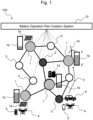
- Fig. 1 is a diagram illustrating an entire configuration of an energy system of Embodiment 1.
- the energy system 100 includes a plurality of nano-grids 1, a plurality of farmlands 2, a plurality of relay points 3, a plurality of drones 4, a plurality of batteries 5, a transportation vehicle 6, and a battery operation plan creation system 10 that is communicatively connected to the nano-grids 1, the farmlands 2, and the like.
- the energy system 100 of Embodiment 1 is a self-sustaining energy system that does not depend on an existing energy system of a large-scale electrical power plant and the like.
- the nano-grid 1 has a power generation facility 1a that performs a photovoltaic power generation, a solar thermal power generation, a hydroelectric power generation, a wind power generation, a geothermal power generation, a wave activated power generation, a temperature difference power generation, a biomass power generation, and the like, and an electricity storage facility 1b that stores electric power generated by the power generation facility 1a.
- the plurality of nano-grids 1 are small-scale power generation and electricity storage facilities and scattered in respective locations.
- a battery 5 mounted on a drone 4 is charged using the electric power generated by the power generation facility 1a or the electric power stored in the electricity storage facility 1b.
- the charged battery 5 is delivered through the relay point 3 or directly to the farmland 2 from the nano-grid 1 by the transportation vehicle 6.
- the battery 5 delivered to the farmland 2 is mounted onto the drone 4, and the drone 4 sprays agricultural chemicals on the farmland 2 and monitors the farmland.
- a demand area where work requiring the battery 5 is performed is not limited to the farmland 2, and may be a factory, a forest, the sea, or the like.
- a used battery 5 used in the farmland 2 is delivered through the relay point 3 or directly to the nano-grid 1 from the farmland 2 by the transportation vehicle 6.
- the battery 5 delivered to the nano-grid 1 is charged using the electric power generated by the power generation facility 1a or the electric power stored in the electricity storage facility 1b.
- the transportation vehicle 6 may be any of electric vehicles, engine vehicles, and hybrid vehicles.
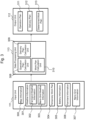
- FIG. 2 is a hardware block diagram of the battery operation plan creation system of Embodiment 1.
- the battery operation plan creation system 10 is an information processing apparatus, for example, a personal computer or a server including a CPU 11 and a memory 14.
- the battery operation plan creation system 10 may be a cloud server.
- a keyboard 17 and a computer mouse 18 are connected as an input device, and a display unit 19 is connected as an output device.
- the battery operation plan creation system 10 includes the Central Processing Unit (CPU) 11, an auxiliary storage device 12, an input I/F 13, the memory 14, a communication I/F 15, and an output I/F 16.
- I/F is abbreviation of an interface.
- the CPU 11 is a central processing unit.
- the CPU 11 may be a Digital Signal Processor (DSP), an Application Specific Integrated Circuit (ASIC), or the like.
- DSP Digital Signal Processor
- ASIC Application Specific Integrated Circuit
- the CPU 11 deploys a program stored in the auxiliary storage device 12 into a work area of the memory 14 to be executable and executes the program.
- the CPU 11 has an input unit 111, an output unit 112, and a data processing unit 113.
- the memory 14 temporarily stores the program that the CPU 11 executes, data that the processor processes, and the like.
- the memory 14 is, for example, a flash memory, a Random Access Memory (RAM), and the like.
- the auxiliary storage device 12 is, for example, a solid state drive
- the above-described keyboard 17 and computer mouse 18 are connected to the input I/F 13.
- the above-described display unit 19 is connected to the output I/F 16.
- the communication I/F 15 is an interface to communicate with external devices (a computer of the nano-grid 1, a computer of the farmland 2, and the like) via a network by wired communication or wireless communication.
- Fig. 3 is a block diagram illustrating a configuration of the CPU of Embodiment 1.
- the CPU 11 has an input unit (input means) 111 where various kinds of data are input, a data processing unit (processing means) 113 that processes the various kinds of data input to the input unit 111, and an output unit (output means) 112 that outputs data processed by the data processing unit 113.
- map information 300 To the input unit 111, map information 300, weather information 301, a temporary work plan 304, battery information 305, farmland information 306, and nano-grid information 307 are input.
- the weather information 301 includes farmland weather information (demand area weather information) 302 including weather information of the farmland 2 and nano-grid weather information 303 including weather information at installation location of the nano-grid 1.
- the temporary work plan 304 is information collected from each farmland 2 and includes a work demand (electric power [W] or a required number of batteries) of the battery 5 required for the work in the farmland 2.
- the battery information 305 is information on a plurality of batteries 5 and, for example, includes information such as an ID of the battery 5, the location of the battery 5, a remaining amount (power storage amount) of the battery 5.
- the farmland information 306 includes information that indicates an ID of the farmland 2, the location (latitude, longitude) of the farmland 2, a size of the farmland 2, and the like.
- the nano-grid information 307 includes information that indicates an ID of the nano-grid 1, the location (latitude, longitude) of the nano-grid 1, a maximum power storage amount of the nano-grid 1, and a power generation capacity of the nano-grid 1.
- the data processing unit 113 includes an operation plan calculation unit 308 calculating an operation plan for the battery 5, a delivery plan calculation unit 309 calculating a delivery plan of the battery 5, a work plan calculation unit 310 correcting or determining the temporary work plan 304 of each farmland 2.
- the operation plan calculation unit 308 creates an operation plan 311 of the plurality of batteries 5 based on the temporary work plan 304 and the farmland weather information 302 input from the input unit 111.
- the delivery plan calculation unit 309 creates a delivery plan 312 of the battery 5 in accordance with the created operation plan 311 of the battery 5.
- the work plan calculation unit 310 corrects or determines the temporary work plan 304 of each farmland 2 in accordance with the created operation plan 311 of the battery 5.
- the output unit 112 outputs the operation plan 311 of the battery 5 calculated by the operation plan calculation unit 308, the delivery plan 312 of the battery 5 calculated by delivery plan calculation unit 309, and a determined work plan 313 corrected or determined by the work plan calculation unit 310.
- the operation plan 311 and the delivery plan 312, which are output, are displayed on the display unit 19.
- the determined work plan 313, which is output, is transmitted to each farmland 2.
- Fig. 4 is a flowchart illustrating an entire configuration of processes executed by the battery operation plan creation system of Embodiment 1. With reference to Fig. 4 , the processes executed by the battery operation plan creation system 10 will be described. Each step in the flowchart of Fig. 4 is executed by the CPU 11 that deploys the program read out from the auxiliary storage device 12 into the memory 14 and executes the program.
- the temporary work plan 304 including the required electric power [W] or the required number of batteries is input for each time.
- the battery operation plan creation system 10 collects the temporary work plans 304 from each farmland 2 via the network (Step S401). Then, the battery operation plan creation system 10 merges the temporary work plans 304 collected from each farmland 2 to create integrated work plans 700 (see Fig. 7 ).
- the battery operation plan creation system 10 refers to the integrated work plans 700 to determine whether or not any work requiring the battery 5 is scheduled in any of the farmlands 2 (Step S402).
- the battery operation plan creation system 10 calculates the operation plan 311 for the battery 5 that allocates the required number of batteries 5 to each farmland 2 (Step S403). Specifically, the battery operation plan creation system 10 calculates the operation plan 311 for the battery 5 based on the integrated work plans 700 and farmland weather information 302.
- the battery operation plan creation system 10 outputs the calculated operation plan 311 for the battery 5 (Step S404). Subsequently, the battery operation plan creation system 10 determines or corrects the temporary work plan 304 for each farmland 2, and transmit the determined work plan 313 to each farmland 2 based on the output operation plan 311 for the battery 5 (Step S405).
- the battery operation plan creation system 10 outputs a delivery source (nano-grid 1 or farmland 2) and a delivery destination (farmland 2 or nano-grid 1) of each battery 5 based on the operation plan 311 for the battery 5 (Step S406).
- the battery operation plan creation system 10 calculates the delivery plan 312 for the battery 5 based on the output delivery source and delivery destination of the battery 5 and the map information 300 (Step S407). Subsequently, the battery operation plan creation system 10 outputs the calculated delivery plan 312 for the battery 5 (Step S408).
- the battery operation plan creation system 10 searches a charge destination for an unworkable battery 5 (Step S409). Specifically, the battery operation plan creation system 10 searches the charge destination for the unworkable battery 5 based on the nano-grid weather information 303 and the nano-grid information 307 regarding the nano-grid 1.
- Fig. 5 is a flowchart illustrating the battery operation plan creation method of Embodiment 1. With reference to Fig. 5 , the creation method of the operation plan 311 for the battery 5 will be described. The flowchart in Fig. 5 is a flowchart illustrating a detail of Step S403 in Fig. 4 .
- the battery operation plan creation system 10 determines whether or not there are one or more workable batteries 5 (Step S501).
- the workable battery 5 is, for example, a fully charged battery 5 or a battery having a remaining amount of power storage amount equal to or more than a threshold value.
- the battery operation plan creation system 10 divides the plurality of batteries 5 into the workable batteries 5 and the unworkable batteries 5 (Step S502). Then, the battery operation plan creation system 10 creates an operation plan for the workable batteries 5 and an operation plan for the unworkable batteries 5, respectively.
- the battery operation plan creation system 10 determines whether or not it is possible to work in each farmland 2 based on the weather information (farmland weather information 302) of each farmland 2 (Step S503).
- the farmland weather information 302 includes information on weather, ambient temperature, precipitation probability, wind direction, wind speed, and the like in the farmland 2.
- the battery operation plan creation system 10 allocates the workable batteries 5 with respect to the work that is to be performed in the farmland 2 (Step S504). Specifically, the battery operation plan creation system 10 allocates the number of batteries 5 that satisfies the work demand (electric power [W] or the required number of batteries) required for the work to be performed in the farmland 2, to the work performed in the farmland 2. Then, the battery operation plan creation system 10 sets the delivery destination of the allocated workable batteries 5 to this farmland 2.
- the work demand electric power [W] or the required number of batteries
- the battery operation plan creation system 10 determines whether or not the workable batteries 5 have been able to be allocated to the work in each workable farmland 2 (Step S505).
- the process proceeds to Step S506, and when the workable batteries 5 have not been able to be allocated to the work in each workable farmland 2, the process proceeds to Step S508.
- the battery operation plan creation system 10 When it is determined that the workable batteries 5 have been able to be allocated to the work in the workable farmland 2 (Yes at Step S505), the battery operation plan creation system 10 does not change and maintain time of the work to which the workable batteries 5 have been able to be allocated (Step S506), and stores the updated operation plan 311 for the batteries 5 (Step S507).
- the battery operation plan creation system 10 delays the time of the work to which the workable batteries 5 have not been able to be allocated (Step S508), and stores the updated operation plan 311 for the batteries 5 (Step S509).
- the battery operation plan creation system 10 delays the time of the work in this farmland 2 (Step S510) and stores the updated operation plan 311 for the batteries 5 (Step S511).
- the battery operation plan creation system 10 confirms a status of each unworkable battery 5 and determines whether or not each battery 5 is under charging (Step S512).
- the battery operation plan creation system 10 reads the nano-grid information 307 and the nano-grid weather information 303 (Step S513).
- the nano-grid information 307 includes, for example, location information of the nano-grid 1, a power storage amount [kWh] stored by the electricity storage facility 1b of the nano-grid 1, a power generation capacity of the nano-grid 1, and the like.
- the nano-grid weather information 303 is chronological information of weather, ambient temperature, precipitation probability, wind direction, wind speed, solar radiation amount, and the like in the nano-grid 1.
- the battery operation plan creation system 10 allocates the unworkable batteries 5 to the nano-grid 1 based on the read nano-grid information 307 (power storage amount, power generation capacity) and nano-grid weather information 303 (Step S514). That is, the delivery destination (charge destination) of the unworkable batteries 5 is set to the nano-grid 1.
- the battery operation plan creation system 10 delays the time of the work in each farmland 2 (Step S515), and stores the updated operation plan 311 for the batteries 5 (Step S516).
- Step S501 when it is determined that there is no workable battery 5 (No at Step S501), the battery operation plan creation system 10 delays the time of the work in each farmland 2 ((Step S517), and stores the updated operation plan 311 for the batteries 5 (Step S518).
- Step S517 and Step S518 are executed, the processes of Step S515 and Step S516 are not redundantly executed.
- the battery operation plan creation system 10 stores a current location and a destination of the batteries 5 (Step S519).
- Fig. 6 is a flowchart illustrating a search calculation of the charge destination of the battery of Embodiment 1. With reference to Fig. 6 , the search calculation of the charge destination of the battery 5 will be described.
- the flowchart in Fig. 6 is a flowchart illustrating a detail of Step S409 in Fig. 4 .
- the battery operation plan creation system 10 determines whether or not the battery 5 needs to be charged (Step S601). For example, when the work requiring the battery 5 is not scheduled for a long period of time, it is determined that the battery 5 does not need to be charged.
- the battery operation plan creation system 10 reads the nano-grid information 307 and the nano-grid weather information 303 (Step S602).
- the battery operation plan creation system 10 allocate the battery 5 that needs to be charged to the nano-grid 1 based on the read nano-grid information 307 and nano-grid weather information 303 (Step S603). Specifically, the battery operation plan creation system 10 allocates the battery 5 that needs to be charged to the charge destination (nano-grid 1) having the largest power storage amount and the large predicted power generation amount at the time closest to the current time. At this time, the battery operation plan creation system 10 sets this charge destination (nano-grid 1) as the delivery destination of the battery 5 that needs to be charged.
- the battery operation plan creation system 10 stores the current location and the destination of the battery 5 (Step S604).
- the battery operation plan creation system 10 sets the current location as the delivery destination of the battery 5 that does not need to be charged (Step S605). Subsequently, the battery operation plan creation system 10 stores the current location and the destination of the battery 5 (Step S606).
- Fig. 7 are diagrams illustrating details of the integrated work plans of Embodiment 1. With reference to Fig 7 , the details of the integrated work plans of Embodiment 1 will be described.
- the integrated work plans 700 indicated in Fig. 7 are data groups in which the temporary work plans 304 collected from each farmland 2 by the battery operation plan creation system 10 are integrated.
- the integrated work plan 700 of Fig. 7(a) is data in a table format indicating an electric power required for each farmland 2 (a required electric power [W]) chronologically.
- the integrated work plan 700 of Fig. 7(a) includes an ID 701, a time 702, and a required electric power 703 of the farmland 2.
- the integrated work plan 700 of Fig. 7(a) at a time "1", the electric power of 10000 [W] is required in a farmland ID "1", the electric power of 7500 [W] is required in a farmland ID "2”, and the electric power of 5000 [W] is required in a farmland ID "3".
- the integrated work plan 700 of Fig. 7(a) is data including the required electric power [W]
- the integrated work plan 700 may be data including the required number of batteries instead of the required electric power [W]. That is, the integrated work plan 700 of Fig. 7(b) is data in a table format illustrating the number of batteries 5 required for each farmland 2 (required number of batteries) chronologically.
- the integrated work plan 700 of Fig. 7(b) includes the ID 701, the time 702, and a required number of batteries 704 of the farmland 2. According to the integrated work plan 700 of Fig. 7(b) , at the time "1", "4" batteries 5 are required in the farmland ID "1", “3" batteries 5 are required in the farmland ID "2”, and “2" batteries 5 are required in the farmland ID "3".
- Fig. 8 is a diagram illustrating a detail of the farmland weather information of Embodiment 1. With reference to Fig. 8 , the detail of the farmland weather information 302 of Embodiment 1 will be described.
- the farmland weather information 302 indicated in Fig. 8 may be weather information obtained from an organization that provides weather information and may be weather information estimated by the battery operation plan creation system 10 from past weather information.
- the battery operation plan creation system 10 stores the farmland weather information 302 indicated in Fig. 8 for each farmland 2.
- the farmland weather information 302 is a data group that chronologically indicates weather information 801 indicating the weather (such as fine weather, rain, and cloudy weather) in the farmland 2, ambient temperature information 802 indicating the ambient temperature [°C] in the farmland 2, precipitation probability information 803 indicating the precipitation probability [%] in the farmland 2, wind direction information 804 indicating the wind direction in the farmland 2, and wind speed information 805 indicating the wind speed [m/s] in the farmland 2.
- weather information 801 indicating the weather (such as fine weather, rain, and cloudy weather) in the farmland 2
- ambient temperature information 802 indicating the ambient temperature [°C] in the farmland
- precipitation probability information 803 indicating the precipitation probability [%] in the farmland
- wind direction information 804 indicating the wind direction in the farmland 2
- wind speed information 805 indicating the wind speed [m/s] in the farmland 2.
- Fig. 9A is a diagram illustrating a detail of the nano-grid information of Embodiment 1. With reference to Fig. 9A , the detail of the nano-grid information 307 of Embodiment 1 will be described.
- the nano-grid information 307 indicated in Fig. 9A is information regarding the nano-grid 1 and includes a nano-grid ID 901 indicating the ID of the nano-grid 1, location information 902 indicating the location (latitude, longitude) of the nano-grid 1, maximum power storage amount information 903 indicating the maximum power storage amount that the electricity storage facility 1b of the nano-grid 1 can store, and solar facility area information 904 indicating the solar facility area [m 2 ]. Since the nano-grid 1 indicated in Fig. 9A is a nano-grid that performs photovoltaic power generation, it has the solar facility area information 904. When the nano-grid 1 is a nano-grid that performs the wind power generation, the number of windmills may be used.
- Fig. 9B is a diagram illustrating a detail of the nano-grid weather information of Embodiment 1. With reference to Fig. 9B , the detail of the nano-grid weather information 303 of Embodiment 1 will be described.
- the nano-grid weather information 303 indicated in Fig. 9B may be weather information obtained from an organization that provides weather information or may be weather information estimated by the battery operation plan creation system 10 from past weather information.
- the battery operation plan creation system 10 stores the nano-grid weather information 303 indicated in Fig. 9B for each nano-grid 1.
- the nano-grid weather information 303 is a data group that chronologically indicates weather information 905 indicating the weather in the nano-grid 1, ambient temperature information 906 indicating the ambient temperature [°C] in the nano-grid 1, precipitation probability information 907 indicating the precipitation probability [%] in the nano-grid 1, wind direction information 908 indicating the wind direction in the nano-grid 1, wind speed information 909 indicating the wind speed [m/s] in the nano-grid 1, solar radiation amount information 910 indicating the solar radiation amount [kWh/m 2 ] in the nano-grid 1, predicted power generation amount information 911 indicating the predicted power generation amount [kW] by the power generation facility 1a in the nano-grid 1, and predicted demand amount information 912 indicating the predicted demand amount [kW] to the nano-grid 1.
- the predicted demand amount is, for example, an electric power demand amount predicted to be used by general households receiving electric power supply from the nano-grid 1.
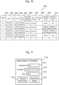
- Fig. 10 is a diagram illustrating the integrated information of Embodiment 1.
- the integrated information is information where various kinds of pieces of information collected from each farmland 2 are integrated and is managed by the battery operation plan creation system 10 in a database.
- Integrated information 1000 includes a farmland ID 1001 indicating the ID of the farmland 2, location information 1002 indicating the location (latitude, longitude) of the farmland 2, size information 1003 indicating the size of the farmland 2.
- the farmland information 306 is information that includes the farmland ID 1001, the location information 1002, and the size information 1003.
- the integrated information 1000 includes a work ID 1004 indicating the ID of the work performed in the farmland 2 and work content information 1005 indicating the content of the work.
- the integrated information 1000 includes a temporarily scheduled work date 1006 indicating the temporarily scheduled date for performing the work, a work due date 1007 indicating the due date of the work, and an unworkable date 1008 when the work cannot be performed.
- the integrated information 1000 includes a scheduled work start date 1009 indicating the scheduled date to start the work and a scheduled work start time 1010 indicating the time to start the work that have been determined by the battery operation plan creation system 10.
- the date and time indicated in the scheduled work start date 1009 and the scheduled work start time 1010 becomes "waiting for determination" when the battery operation plan creation system 10 has not determined.
- the date and time indicated in the scheduled work start date 1009 and the scheduled work start time 1010 are appropriately changed based on the farmland weather information 302 and the like.
- Fig. 11 is a diagram illustrating a screen for inputting the farmland information in Embodiment 1.
- a user of the computer of the farmland 2 can transmit the farmland information 306 to the battery operation plan creation system 10 via the farmland information input screen 1100 in Fig. 11 .
- the farmland information input screen 1100 in Fig. 11 is a screen displayed by a web browser installed on the computer of the farmland 2 based on, for example, HTML data provided by the battery operation plan creation system 10 as a Web server.
- the farmland information input screen 1100 is a screen for inputting the farmland information 306 and includes a farmland ID input field 1101 for inputting the farmland ID, a location input field 1102 for inputting the location (latitude, longitude) of the farmland 2, a size input field 1103 for inputting the size of the farmland 2, a work plan transmission button 1104 for displaying a work plan input screen 11040 for inputting the temporary work plan 304 for the farmland 2, and a work plan result display button 1105 for displaying a list of the temporary work plan 304 and the determined work plan 313 that have been inputted.
- the required electric power [W] and the required number of batteries in the work plan are determined by the size of the farmland 2.
- Fig. 12 is a diagram illustrating a screen for inputting the temporary work plan of Embodiment 1.
- the work plan input screen 11040 of Fig. 12 is a screen displayed when the work plan transmission button 1104 in Fig. 11 is selected by a user.
- the work plan input screen 11040 includes a work ID input field 11041 for inputting the work ID, a work content input field 11042 for inputting the work content, a temporarily scheduled date input field 11043 for inputting the temporarily scheduled work date, a due date input field 11044 for inputting the work due date, and an unworkable date selection unit 11045 specifying the unworkable date.
- the work plan input screen 11040 includes a return button 11046 for returning to the farmland information input screen 1100 as a previous screen and a transmission button 11047 for transmitting information input into the work plan input screen 11040 to the battery operation plan creation system 10.
- Fig. 13 is a diagram illustrating a list screen of the work plan of Embodiment 1.
- the list screen 11050 indicated in Fig. 13 is a screen displayed when the work plan result display button 1105 in Fig. 11 is selected by a user.
- the list screen 11050 is a screen that displays a list of the temporary work plan 304 and the determined work plan 313 that are to be performed in the farmland 2.
- the list screen 11050 displays details of the work (a work content 11052, a temporarily scheduled work date 11053, a work due date 11054, a scheduled work start date 11056, a scheduled work start time 11057) input on the work plan input screen 11040 for each work ID 11051.
- the list screen 11050 includes a memo entry button 11058 for inputting a memo and a correction request button 11059 for correcting the temporary work plan 304 and the determined work plan 313, for each work ID 11051.
- the list screen 11050 includes a return button 110510 for returning to the farmland information input screen 1100 as a previous screen.
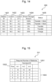
- Fig. 14 is a diagram illustrating the battery information of Embodiment 1.
- the battery information 305 indicated in Fig. 14 is information of the plurality of batteries 5 managed by the battery operation plan creation system 10.
- the battery information 305 includes a battery ID 1401 indicating the ID of the battery 5, location (t) information 1402 indicating the location of the battery 5 at a time t, location (t+1) information 1403 indicating the location of the battery 5 at a time t+1, power storage amount information 1404 indicating the power storage amount of the battery 5, and status information 1405 indicating the status of the battery 5.
- the power storage amount information 1404 may be displayed in % or may be the remaining capacity [kWh].
- Fig. 15 is a diagram illustrating the battery operation plan of the battery of Embodiment 1. With reference to Fig. 15 , details of the operation plan 311 of the battery 5 of Embodiment 1 will be described.
- the operation plan 311 of the battery 5 indicated in Fig. 15 is data in a table format chronologically indicating the number of batteries required for each farmland 2.
- the operation plan 311 includes an ID 1501, a time 1502, and a required number of batteries 1503 of the farmland 2.
- the operation plan 311 in Fig. 15 indicates that at a time "1", 10 batteries 5 are required for farmland ID "A-1", 10 batteries 5 are required for farmland ID "A-2”, and 10 batteries 5 are required for farmland ID "A-3".
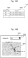
- Fig. 16A is a diagram illustrating the delivery plan of the battery of Embodiment 1. With reference to Fig. 16A , details of the delivery plan 312 of the battery 5 of Embodiment 1 will be described.
- the delivery plan 312 of the battery 5 includes a battery ID 1601 indicating the ID of the battery 5 and route information 1602 indicating a delivery route of the battery 5.
- the delivery plan 312 of the battery 5 in Fig. 16A indicates a route along which the battery 5 with the battery ID 1601 of "B-1" is delivered from the nano-grid (N-1) to the farmland (A-1) via the relay point (V-139) and the relay point (V-158).
- Fig. 16B is a diagram illustrating the delivery map of Embodiment 1. With reference to Fig. 16B , the delivery map 1603 of the battery 5 of Embodiment 1 will be described.
- the delivery map 1603 indicated in Fig. 16B includes a selection box 1604 for selecting the battery ID and map information 1605 where each point of the route information 1602 is plotted on the map.
- a user can confirm a route along which the battery 5 with the battery ID "B-1" is delivered between the time t and the time t+1 on the map.
- the map used for the map information 1605 is created based on the map information 300.
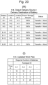
- Fig. 17 includes a diagram illustrating an initial operation plan for the battery of Embodiment 1, a diagram illustrating an updated operation plan for the battery of Embodiment 1, and a diagram illustrating a delivery plan for the battery of Embodiment 1.
- the operation plan, the updated operation plan, and the battery delivery for the battery 5 of Embodiment 1 will be described.
- the operation plan and the delivery plan for 30 batteries 5 with a power storage amount of 100% prepared in the nano-grid 1 (ID: N-1) will be described.
- the battery operation plan creation system 10 collects the temporary work plans 304 from each farmland 2. As indicated in an initial operation plan 1701 in Fig. 17(A) , the battery operation plan creation system 10 receives the temporary work plan 304 that requires 10 batteries 5 at a time "1" from the farmland 2 with the farmland ID "A-1”, receives the temporary work plan 304 that requires 10 batteries 5 at the time "1” from the farmland 2 with the farmland ID "A-2”, and receives the temporary work plan 304 that requires 20 batteries 5 at the time "1" from the farmland 2 with the farmland ID "A-3".
- the battery operation plan creation system 10 delays the time of the work in the farmland 2 with the farmland ID "A-1” as indicated in an updated operation plan 1702 in Fig. 17(B) .
- the battery operation plan creation system 10 allocates the batteries 5 to the work in the farmland 2 with the farmland ID "A-2" and the work in the farmland 2 with the farmland ID "A-3", and delays the time of the work in the farmland 2 with the farmland ID "A-1". For the works at the same time, the battery operation plan creation system 10 allocates the batteries 5 by prioritizing in accordance with at least one of:
- the battery operation plan creation system 10 creates the delivery plan for the batteries 5 based on the updated operation plan 1702 in Fig. 17(B) . As indicated in Fig. 17(C) , the battery operation plan creation system 10 creates the delivery plan for 30 batteries 5 with the battery IDs of "B-1" to "B-30". Specifically, to deliver 10 batteries 5 to the farmland 2 with the farmland ID "A-2", the battery operation plan creation system 10 sets the location of the 10 batteries 5 with the battery IDs of "B-1" to "B-10" at time (t+1) to "A-2".
- the battery operation plan creation system 10 sets the location of the 20 batteries 5 with the battery IDs of "B-11" to "B-30” at time (t+1) to "A-3". Then, the status of each battery 5 is set to "transfer”.
- the operation plan calculation unit 308 of the data processing unit 113 creates the operation plan for the plurality of batteries 5 in the farmland 2 based on the temporary work plan 304 input by the input unit 111 and the farmland weather information 302. This allows creating the efficient operation plan 311 for the batteries 5 while considering uncertainties such as a farm work time caused by weather fluctuation.
- the data processing unit 113 determines the nano-grid 1 for charging the plurality of batteries 5 based on the nano-grid weather information 303 and the nano-grid information 307. This allows improving usage efficiency of renewable energy and performing efficient charge of the battery 5 while considering uncertainties such as charge efficiency at the nano-grid 1 caused by weather fluctuation.
- the delivery plan calculation unit 309 of the data processing unit 113 creates the delivery plan 312 for delivering the plurality of batteries 5 from the nano-grid 1 to the farmland 2 in accordance with the operation plan 311 for the battery 5. This allows easily grasping the locations and the status of the plurality of batteries 5.
- the data processing unit 113 outputs the determined work plan 313, which is determined, to the computer (output device) of the farmland 2. This allows confirming a work start time and the like in the farmland 2 and performing the work efficiently by referring to the determined work plan 313.
- the data processing unit 113 allocates the batteries 5 in accordance with at least one preferential order of:
- the batteries 5 can be allocated to the work at the same time in accordance with the predetermined preferential order, it is possible to perform the work requiring the battery 5 in this order from the work having a higher priority.
- the work time for the work can be delayed. As a result, the work can be executed when the battery 5 becomes allocatable.
- Embodiment 1 while the operation plan and the delivery plan for 30 batteries 5 with a power storage amount of 100% prepared in the nano-grid 1 (ID: N-1) have been described, in Embodiment 2, the operation plan and the delivery plan for 20 batteries 5 with a power storage amount of 100% prepared in the nano-grid 1 (ID: N-1) will be described. Descriptions overlapping those of Embodiment 1 will be appropriately omitted.
- the battery operation plan creation system 10 collects the temporary work plans 304 from each farmland 2.
- An initial operation plan 1801 in Fig. 18(A) is the same as the initial operation plan 1701 in Fig. 17(A) of Embodiment 1.
- the battery operation plan creation system 10 allocates the batteries 5 to the work in the farmland 2 with the farmland ID "A-1" and the work in the farmland 2 with the farmland ID "A-2", and delays the time of the work in the farmland 2 with the farmland ID "A-3".
- the battery operation plan creation system 10 creates the delivery plan for the batteries 5 based on the updated operation plan 1802 in Fig. 18(B) . As indicated in Fig. 18(C) , the battery operation plan creation system 10 creates the delivery plan for 20 batteries 5 with the battery IDs "B-1" to "B-20” at the time "1". Specifically, in order to deliver 10 batteries 5 to the farmland 2 with the farmland ID "A-2", the battery operation plan creation system 10 sets the location of the 10 batteries 5 with the battery IDs "B-1" to "B-10" at a time (t+1) to "A-2".
- the battery operation plan creation system 10 sets the location of the 10 batteries 5 with the battery IDs "B-11" to "B-20” at the time (t+1) to "A-1". Then, the battery operation plan creation system 10 sets the status of each battery 5 to "transfer + work".
- the battery operation plan creation system 10 creates the delivery plan and the operation plan for 20 batteries 5 with the battery IDs "B-1" to “B-20” at a time "2".
- the battery operation plan creation system 10 sets the power storage amount of the batteries 5 with the battery IDs "B-1" to "B-20” to "0 [%]".
- the battery operation plan creation system 10 Since there is no workable battery 5 at the time "2", the battery operation plan creation system 10 needs to deliver it to the charge destination (nano-grid 1) of the battery 5.
- the battery operation plan creation system 10 determines the delivery destination of the unworkable batteries 5 based on the nano-grid weather information 303 and the like. While the nano-grids N-1 and N-2 exist as the delivery destinations (charge destinations) of the batteries 5, when the weather in the nano-grid N-2 is "fine weather” and the weather in the nano-grid N-1 is “rain”, the battery operation plan creation system 10 selects the nano-grid N-2 as the charge destination of the batteries 5 and sets the nano-grid N-2 as the delivery destination of the batteries 5.
- the battery operation plan creation system 10 delays the time of the work in the farmland 2 with the farmland ID "A-3" at the time "2".
- the battery operation plan creation system 10 creates the delivery plan and the operation plan for 20 batteries 5 with the battery IDs "B-1" to “B-20” at a time "3". As indicated in Fig. 19(F), in order to charge the batteries 5 with the battery IDs "B-1" to “B-20” by the nano-grid N-2, the battery operation plan creation system 10 keeps the location of batteries 5 at N-2. Then, the battery operation plan creation system 10 sets the status of each battery 5 to "under charging”.
- the battery operation plan creation system 10 further delays the time of the work in the farmland 2 with the farmland ID "A-3" at the time "3".
- the battery operation plan creation system 10 creates the delivery plan and the operation plan for 20 batteries 5 with the battery IDs "B-1" to “B-20” at a time "4".
- the battery operation plan creation system 10 sets the location of the batteries 5 to "A-3". Then, the battery operation plan creation system 10 sets the status of each battery 5 as "transfer + work”.
- the battery operation plan creation system 10 allocates the workable batteries 5 to the work in the farmland 2 with the farmland ID "A-3" at the time "4".
- Embodiment 2 compared with Embodiment 1, the work in the farmland 2 can be performed with a smaller number of batteries 5. This allows suppressing cost increase required for the battery 5. Other effects are the same as those of Embodiment 1.
- the present disclosure is not limited to the embodiments described above and includes various modifications.
- the Embodiments described above have been described in detail to facilitate understanding of the present disclosure and are not necessarily limited to those having all the described configuration. It is also possible to replace part of the configuration of one Embodiment with the configuration of another Embodiment, and it is also possible to add the configuration of another Embodiment to the configuration of one Embodiment. It is also possible to add, delete, or replace part of the configuration of each Embodiment with another configuration.
Landscapes
- Engineering & Computer Science (AREA)
- Business, Economics & Management (AREA)
- Human Resources & Organizations (AREA)
- Power Engineering (AREA)
- Transportation (AREA)
- Mechanical Engineering (AREA)
- Strategic Management (AREA)
- Economics (AREA)
- Entrepreneurship & Innovation (AREA)
- Theoretical Computer Science (AREA)
- Tourism & Hospitality (AREA)
- General Physics & Mathematics (AREA)
- General Business, Economics & Management (AREA)
- Physics & Mathematics (AREA)
- Marketing (AREA)
- Life Sciences & Earth Sciences (AREA)
- Development Economics (AREA)
- Quality & Reliability (AREA)
- Operations Research (AREA)
- Game Theory and Decision Science (AREA)
- Educational Administration (AREA)
- Biodiversity & Conservation Biology (AREA)
- Animal Husbandry (AREA)
- Agronomy & Crop Science (AREA)
- Mining & Mineral Resources (AREA)
- Health & Medical Sciences (AREA)
- General Health & Medical Sciences (AREA)
- Marine Sciences & Fisheries (AREA)
- Primary Health Care (AREA)
- Management, Administration, Business Operations System, And Electronic Commerce (AREA)
Abstract
Description
- The present disclosure relates to an information processing apparatus, an energy system, and a battery operation plan creation method.
- In recent years, as a new energy system, development of an energy system with a nano-grid as a base unit that includes small-scale renewable energy sources, which utilizes sunlight or the like, is being promoted. The energy system is a self-sustaining energy system (for example, see Patent Literature 1) that is independent of an existing energy system such as a large-scale electrical power plant, and is expected as an electric power source for a regional industry (agriculture) and an emergency power source during a disaster.
- Patent Literature 1:
JP 2021-528752 A - To assist a regional industry (agriculture), in a region where nano-grids are arranged, it is being considered to charge batteries for agricultural drones with nano-grid power generation and power storage facilities, and deliver large amounts of batteries to each farmland from this charging base.
- However, in preparation for extension of farm work time due to bad weather or the like and charging using renewable energy where electric power supply is unstable, it was necessary to prepare an excess battery compared with a work plan of a scheduled work, which increased cost by that amount.
- To assist the regional industry (agriculture) using a small-scale self-sustaining energy system, an efficient battery operation plan must be created while considering uncertainties of a farm work time or the like caused by weather fluctuation.
- Therefore, the present disclosure provides an information processing apparatus, an energy system, and a battery operation plan creation method that allow creating an efficient battery operation plan while considering uncertainties of a farm work time or the like caused by weather fluctuation.
- An information processing apparatus of the present disclosure creates an operation plan for a plurality of batteries charged at a nano-grid including at least one of a power generation facility or an electricity storage facility. The information processing apparatus includes: an input means that inputs a work plan including a work demand for the battery required for a work in a demand area and demand area weather information indicating a weather of the demand area; and a processing means that creates the operation plan for the plurality of batteries in the demand area based on the work plan and the demand area weather information input by the input means.
- With the present disclosure, the efficient battery operation plan can be created while considering uncertainties of a farm work time or the like caused by weather fluctuation.
-
-
Fig. 1 is a diagram illustrating an entire configuration of an energy system ofEmbodiment 1. -
Fig. 2 is a hardware block diagram of a battery operation plan creation system ofEmbodiment 1. -
Fig. 3 is a block diagram illustrating a configuration of a CPU ofEmbodiment 1. -
Fig. 4 is a flowchart illustrating an entire configuration of processes executed by the battery operation plan creation system ofEmbodiment 1. -
Fig. 5 is a flowchart illustrating a battery operation plan creation method ofEmbodiment 1. -
Fig. 6 is a flowchart illustrating a search calculation of a battery charge destination ofEmbodiment 1. -
Fig. 7 include diagrams illustrating details of integrated work plans ofEmbodiment 1. -
Fig. 8 is a diagram illustrating a detail of farmland weather information ofEmbodiment 1. -
Fig. 9A is a diagram illustrating a detail of nano-grid information ofEmbodiment 1. -
Fig. 9B is a diagram illustrating a detail of nano-grid weather information ofEmbodiment 1. -
Fig. 10 is a diagram illustrating integrated information ofEmbodiment 1. -
Fig. 11 is a diagram illustrating a screen for inputting farmland information ofEmbodiment 1. -
Fig. 12 is a diagram illustrating a screen for inputting a temporary work plan ofEmbodiment 1. -
Fig. 13 is a diagram illustrating a list screen of a work plan ofEmbodiment 1. -
Fig. 14 is a diagram illustrating battery information ofEmbodiment 1. -
Fig. 15 is a diagram illustrating a battery operation plan ofEmbodiment 1. -
Fig. 16A is a diagram illustrating a battery delivery plan ofEmbodiment 1. -
Fig. 16B is a diagram illustrating a delivery map ofEmbodiment 1. -
Fig. 17 includes a diagram illustrating an initial battery operation plan ofEmbodiment 1, a diagram illustrating an updated battery operation plan ofEmbodiment 1, and a diagram illustrating a battery delivery plan ofEmbodiment 1. -
Fig. 18 includes diagrams illustrating battery operation plans ofEmbodiment 2, and a diagrams illustrating a battery delivery plan ofEmbodiment 2. -
Fig. 19 includes diagrams illustrating battery operation plans ofEmbodiment 2, and diagrams illustrating battery delivery plans ofEmbodiment 2. -
Fig. 20 includes a diagram illustrating a battery operation plan ofEmbodiment 2, and a diagram illustrating a battery delivery plan ofEmbodiment 2. - Embodiments of this disclosure will be described in detail based on the drawings. In the following Embodiments, it goes without saying that components (including element steps and the like) of the Embodiments are not necessarily indispensable except in cases where it is clearly stated, it is clearly indispensable in principle, and the like.
-
Fig. 1 is a diagram illustrating an entire configuration of an energy system ofEmbodiment 1. Theenergy system 100 includes a plurality of nano-grids 1, a plurality offarmlands 2, a plurality ofrelay points 3, a plurality ofdrones 4, a plurality ofbatteries 5, atransportation vehicle 6, and a battery operationplan creation system 10 that is communicatively connected to the nano-grids 1, thefarmlands 2, and the like. Theenergy system 100 ofEmbodiment 1 is a self-sustaining energy system that does not depend on an existing energy system of a large-scale electrical power plant and the like. - The nano-
grid 1 has apower generation facility 1a that performs a photovoltaic power generation, a solar thermal power generation, a hydroelectric power generation, a wind power generation, a geothermal power generation, a wave activated power generation, a temperature difference power generation, a biomass power generation, and the like, and anelectricity storage facility 1b that stores electric power generated by thepower generation facility 1a. The plurality of nano-grids 1 are small-scale power generation and electricity storage facilities and scattered in respective locations. In this nano-grid 1, abattery 5 mounted on adrone 4 is charged using the electric power generated by thepower generation facility 1a or the electric power stored in theelectricity storage facility 1b. - The
charged battery 5 is delivered through therelay point 3 or directly to thefarmland 2 from the nano-grid 1 by thetransportation vehicle 6. Thebattery 5 delivered to thefarmland 2 is mounted onto thedrone 4, and thedrone 4 sprays agricultural chemicals on thefarmland 2 and monitors the farmland. A demand area where work requiring thebattery 5 is performed is not limited to thefarmland 2, and may be a factory, a forest, the sea, or the like. - A used
battery 5 used in thefarmland 2 is delivered through therelay point 3 or directly to the nano-grid 1 from thefarmland 2 by thetransportation vehicle 6. Thebattery 5 delivered to the nano-grid 1 is charged using the electric power generated by thepower generation facility 1a or the electric power stored in theelectricity storage facility 1b. Thetransportation vehicle 6 may be any of electric vehicles, engine vehicles, and hybrid vehicles. -
FIG. 2 is a hardware block diagram of the battery operation plan creation system ofEmbodiment 1. The battery operationplan creation system 10 is an information processing apparatus, for example, a personal computer or a server including aCPU 11 and amemory 14. The battery operationplan creation system 10 may be a cloud server. To the battery operationplan creation system 10, akeyboard 17 and acomputer mouse 18 are connected as an input device, and adisplay unit 19 is connected as an output device. - The battery operation
plan creation system 10 includes the Central Processing Unit (CPU) 11, anauxiliary storage device 12, an input I/F 13, thememory 14, a communication I/F 15, and an output I/F 16. I/F is abbreviation of an interface. TheCPU 11 is a central processing unit. TheCPU 11 may be a Digital Signal Processor (DSP), an Application Specific Integrated Circuit (ASIC), or the like. TheCPU 11 deploys a program stored in theauxiliary storage device 12 into a work area of thememory 14 to be executable and executes the program. TheCPU 11 has aninput unit 111, anoutput unit 112, and adata processing unit 113. Thememory 14 temporarily stores the program that theCPU 11 executes, data that the processor processes, and the like. Thememory 14 is, for example, a flash memory, a Random Access Memory (RAM), and the like. Theauxiliary storage device 12 is, for example, a solid state drive device (SSD), a hard disk drive device (HDD), and the like. - The above-described
keyboard 17 andcomputer mouse 18 are connected to the input I/F 13. The above-describeddisplay unit 19 is connected to the output I/F 16. The communication I/F 15 is an interface to communicate with external devices (a computer of the nano-grid 1, a computer of thefarmland 2, and the like) via a network by wired communication or wireless communication. -
Fig. 3 is a block diagram illustrating a configuration of the CPU ofEmbodiment 1. TheCPU 11 has an input unit (input means) 111 where various kinds of data are input, a data processing unit (processing means) 113 that processes the various kinds of data input to theinput unit 111, and an output unit (output means) 112 that outputs data processed by thedata processing unit 113. - To the
input unit 111,map information 300,weather information 301, atemporary work plan 304,battery information 305,farmland information 306, and nano-grid information 307 are input. Theweather information 301 includes farmland weather information (demand area weather information) 302 including weather information of thefarmland 2 and nano-grid weather information 303 including weather information at installation location of the nano-grid 1. Thetemporary work plan 304 is information collected from eachfarmland 2 and includes a work demand (electric power [W] or a required number of batteries) of thebattery 5 required for the work in thefarmland 2. Thebattery information 305 is information on a plurality ofbatteries 5 and, for example, includes information such as an ID of thebattery 5, the location of thebattery 5, a remaining amount (power storage amount) of thebattery 5. Thefarmland information 306 includes information that indicates an ID of thefarmland 2, the location (latitude, longitude) of thefarmland 2, a size of thefarmland 2, and the like. The nano-grid information 307 includes information that indicates an ID of the nano-grid 1, the location (latitude, longitude) of the nano-grid 1, a maximum power storage amount of the nano-grid 1, and a power generation capacity of the nano-grid 1. - The
data processing unit 113 includes an operationplan calculation unit 308 calculating an operation plan for thebattery 5, a deliveryplan calculation unit 309 calculating a delivery plan of thebattery 5, a workplan calculation unit 310 correcting or determining thetemporary work plan 304 of eachfarmland 2. The operationplan calculation unit 308 creates anoperation plan 311 of the plurality ofbatteries 5 based on thetemporary work plan 304 and thefarmland weather information 302 input from theinput unit 111. The deliveryplan calculation unit 309 creates adelivery plan 312 of thebattery 5 in accordance with the createdoperation plan 311 of thebattery 5. The workplan calculation unit 310 corrects or determines thetemporary work plan 304 of eachfarmland 2 in accordance with the createdoperation plan 311 of thebattery 5. - The
output unit 112 outputs theoperation plan 311 of thebattery 5 calculated by the operationplan calculation unit 308, thedelivery plan 312 of thebattery 5 calculated by deliveryplan calculation unit 309, and adetermined work plan 313 corrected or determined by the workplan calculation unit 310. Theoperation plan 311 and thedelivery plan 312, which are output, are displayed on thedisplay unit 19. Thedetermined work plan 313, which is output, is transmitted to eachfarmland 2. -
Fig. 4 is a flowchart illustrating an entire configuration of processes executed by the battery operation plan creation system ofEmbodiment 1. With reference toFig. 4 , the processes executed by the battery operationplan creation system 10 will be described. Each step in the flowchart ofFig. 4 is executed by theCPU 11 that deploys the program read out from theauxiliary storage device 12 into thememory 14 and executes the program. - In each
farmland 2, to perform the work requiring thebattery 5, thetemporary work plan 304 including the required electric power [W] or the required number of batteries is input for each time. The battery operationplan creation system 10 collects the temporary work plans 304 from eachfarmland 2 via the network (Step S401). Then, the battery operationplan creation system 10 merges the temporary work plans 304 collected from eachfarmland 2 to create integrated work plans 700 (seeFig. 7 ). - The battery operation
plan creation system 10 refers to the integrated work plans 700 to determine whether or not any work requiring thebattery 5 is scheduled in any of the farmlands 2 (Step S402). - When it is determined that a work requiring the
battery 5 is scheduled in any of the farmlands 2 (Yes at Step S402), the battery operationplan creation system 10 calculates theoperation plan 311 for thebattery 5 that allocates the required number ofbatteries 5 to each farmland 2 (Step S403). Specifically, the battery operationplan creation system 10 calculates theoperation plan 311 for thebattery 5 based on the integrated work plans 700 andfarmland weather information 302. - Then, the battery operation
plan creation system 10 outputs the calculatedoperation plan 311 for the battery 5 (Step S404). Subsequently, the battery operationplan creation system 10 determines or corrects thetemporary work plan 304 for eachfarmland 2, and transmit thedetermined work plan 313 to eachfarmland 2 based on theoutput operation plan 311 for the battery 5 (Step S405). - Next, the battery operation
plan creation system 10 outputs a delivery source (nano-grid 1 or farmland 2) and a delivery destination (farmland 2 or nano-grid 1) of eachbattery 5 based on theoperation plan 311 for the battery 5 (Step S406). - Then, the battery operation
plan creation system 10 calculates thedelivery plan 312 for thebattery 5 based on the output delivery source and delivery destination of thebattery 5 and the map information 300 (Step S407). Subsequently, the battery operationplan creation system 10 outputs the calculateddelivery plan 312 for the battery 5 (Step S408). - At Step S402, when it is determined that a work requiring the
battery 5 is not scheduled in any of the farmlands 2 (No at Step S402), the battery operationplan creation system 10 searches a charge destination for an unworkable battery 5 (Step S409). Specifically, the battery operationplan creation system 10 searches the charge destination for theunworkable battery 5 based on the nano-grid weather information 303 and the nano-grid information 307 regarding the nano-grid 1. -
Fig. 5 is a flowchart illustrating the battery operation plan creation method ofEmbodiment 1. With reference toFig. 5 , the creation method of theoperation plan 311 for thebattery 5 will be described. The flowchart inFig. 5 is a flowchart illustrating a detail of Step S403 inFig. 4 . - First, the battery operation
plan creation system 10 determines whether or not there are one or more workable batteries 5 (Step S501). Theworkable battery 5 is, for example, a fully chargedbattery 5 or a battery having a remaining amount of power storage amount equal to or more than a threshold value. - When it is determined that there are one or more workable batteries 5 (Yes at Step S501), the battery operation
plan creation system 10 divides the plurality ofbatteries 5 into theworkable batteries 5 and the unworkable batteries 5 (Step S502). Then, the battery operationplan creation system 10 creates an operation plan for theworkable batteries 5 and an operation plan for theunworkable batteries 5, respectively. - Regarding the
workable batteries 5, the battery operationplan creation system 10 determines whether or not it is possible to work in eachfarmland 2 based on the weather information (farmland weather information 302) of each farmland 2 (Step S503). Thefarmland weather information 302 includes information on weather, ambient temperature, precipitation probability, wind direction, wind speed, and the like in thefarmland 2. - When it is determined that it is possible to work (for example, the weather in the
farmland 2 is "fine weather") in the farmland 2 (Yes at Step S503), the battery operationplan creation system 10 allocates theworkable batteries 5 with respect to the work that is to be performed in the farmland 2 (Step S504). Specifically, the battery operationplan creation system 10 allocates the number ofbatteries 5 that satisfies the work demand (electric power [W] or the required number of batteries) required for the work to be performed in thefarmland 2, to the work performed in thefarmland 2. Then, the battery operationplan creation system 10 sets the delivery destination of the allocatedworkable batteries 5 to thisfarmland 2. - Next, the battery operation
plan creation system 10 determines whether or not theworkable batteries 5 have been able to be allocated to the work in each workable farmland 2 (Step S505). When theworkable batteries 5 have been able to be allocated to the work in eachworkable farmland 2, the process proceeds to Step S506, and when theworkable batteries 5 have not been able to be allocated to the work in eachworkable farmland 2, the process proceeds to Step S508. - When it is determined that the
workable batteries 5 have been able to be allocated to the work in the workable farmland 2 (Yes at Step S505), the battery operationplan creation system 10 does not change and maintain time of the work to which theworkable batteries 5 have been able to be allocated (Step S506), and stores the updatedoperation plan 311 for the batteries 5 (Step S507). - When it is determined that the
workable batteries 5 have not been able to be allocated to the work in the workable farmland 2 (No at Step S505), the battery operationplan creation system 10 delays the time of the work to which theworkable batteries 5 have not been able to be allocated (Step S508), and stores the updatedoperation plan 311 for the batteries 5 (Step S509). - On the other hand, when it is determined that it is impossible to work in the farmland 2 (for example, the weather of the
farmland 2 is "rain") (No at Step S503), the battery operationplan creation system 10 delays the time of the work in this farmland 2 (Step S510) and stores the updatedoperation plan 311 for the batteries 5 (Step S511). - Regarding the
unworkable batteries 5, the battery operationplan creation system 10 confirms a status of eachunworkable battery 5 and determines whether or not eachbattery 5 is under charging (Step S512). - When it is determined that each
battery 5 is not under charging (No at Step S512), the battery operationplan creation system 10 reads the nano-grid information 307 and the nano-grid weather information 303 (Step S513). The nano-grid information 307 includes, for example, location information of the nano-grid 1, a power storage amount [kWh] stored by theelectricity storage facility 1b of the nano-grid 1, a power generation capacity of the nano-grid 1, and the like. The nano-grid weather information 303 is chronological information of weather, ambient temperature, precipitation probability, wind direction, wind speed, solar radiation amount, and the like in the nano-grid 1. - Then, the battery operation
plan creation system 10 allocates theunworkable batteries 5 to the nano-grid 1 based on the read nano-grid information 307 (power storage amount, power generation capacity) and nano-grid weather information 303 (Step S514). That is, the delivery destination (charge destination) of theunworkable batteries 5 is set to the nano-grid 1. - On the other hand, when it is determined that each
battery 5 is under charging (Yes at Step S512), the battery operationplan creation system 10 delays the time of the work in each farmland 2 (Step S515), and stores the updatedoperation plan 311 for the batteries 5 (Step S516). - At Step S501, when it is determined that there is no workable battery 5 (No at Step S501), the battery operation
plan creation system 10 delays the time of the work in each farmland 2 ((Step S517), and stores the updatedoperation plan 311 for the batteries 5 (Step S518). When the processes of Step S517 and Step S518 are executed, the processes of Step S515 and Step S516 are not redundantly executed. - Then, after storing the updated
operation plan 311 for the batteries 5 (Step S507, Step S509, Step S511, Step S516), the battery operationplan creation system 10 stores a current location and a destination of the batteries 5 (Step S519). -
Fig. 6 is a flowchart illustrating a search calculation of the charge destination of the battery ofEmbodiment 1. With reference toFig. 6 , the search calculation of the charge destination of thebattery 5 will be described. The flowchart inFig. 6 is a flowchart illustrating a detail of Step S409 inFig. 4 . - First, the battery operation
plan creation system 10 determines whether or not thebattery 5 needs to be charged (Step S601). For example, when the work requiring thebattery 5 is not scheduled for a long period of time, it is determined that thebattery 5 does not need to be charged. - Regarding the
battery 5 that needs to be charged (Yes at Step S601), the battery operationplan creation system 10 reads the nano-grid information 307 and the nano-grid weather information 303 (Step S602). - Then, the battery operation
plan creation system 10 allocate thebattery 5 that needs to be charged to the nano-grid 1 based on the read nano-grid information 307 and nano-grid weather information 303 (Step S603). Specifically, the battery operationplan creation system 10 allocates thebattery 5 that needs to be charged to the charge destination (nano-grid 1) having the largest power storage amount and the large predicted power generation amount at the time closest to the current time. At this time, the battery operationplan creation system 10 sets this charge destination (nano-grid 1) as the delivery destination of thebattery 5 that needs to be charged. - Then, the battery operation
plan creation system 10 stores the current location and the destination of the battery 5 (Step S604). - Regarding the
battery 5 that does not need to be charged (No at Step S601), the battery operationplan creation system 10 sets the current location as the delivery destination of thebattery 5 that does not need to be charged (Step S605). Subsequently, the battery operationplan creation system 10 stores the current location and the destination of the battery 5 (Step S606). -
Fig. 7 are diagrams illustrating details of the integrated work plans ofEmbodiment 1. With reference toFig 7 , the details of the integrated work plans ofEmbodiment 1 will be described. The integrated work plans 700 indicated inFig. 7 are data groups in which the temporary work plans 304 collected from eachfarmland 2 by the battery operationplan creation system 10 are integrated. - The
integrated work plan 700 ofFig. 7(a) is data in a table format indicating an electric power required for each farmland 2 (a required electric power [W]) chronologically. Theintegrated work plan 700 ofFig. 7(a) includes anID 701, atime 702, and a requiredelectric power 703 of thefarmland 2. According to theintegrated work plan 700 ofFig. 7(a) , at a time "1", the electric power of 10000 [W] is required in a farmland ID "1", the electric power of 7500 [W] is required in a farmland ID "2", and the electric power of 5000 [W] is required in a farmland ID "3". - While the
integrated work plan 700 ofFig. 7(a) is data including the required electric power [W], theintegrated work plan 700 may be data including the required number of batteries instead of the required electric power [W]. That is, theintegrated work plan 700 ofFig. 7(b) is data in a table format illustrating the number ofbatteries 5 required for each farmland 2 (required number of batteries) chronologically. Theintegrated work plan 700 ofFig. 7(b) includes theID 701, thetime 702, and a required number ofbatteries 704 of thefarmland 2. According to theintegrated work plan 700 ofFig. 7(b) , at the time "1", "4"batteries 5 are required in the farmland ID "1", "3"batteries 5 are required in the farmland ID "2", and "2"batteries 5 are required in the farmland ID "3". -
Fig. 8 is a diagram illustrating a detail of the farmland weather information ofEmbodiment 1. With reference toFig. 8 , the detail of thefarmland weather information 302 ofEmbodiment 1 will be described. Thefarmland weather information 302 indicated inFig. 8 may be weather information obtained from an organization that provides weather information and may be weather information estimated by the battery operationplan creation system 10 from past weather information. The battery operationplan creation system 10 stores thefarmland weather information 302 indicated inFig. 8 for eachfarmland 2. - The
farmland weather information 302 is a data group that chronologically indicatesweather information 801 indicating the weather (such as fine weather, rain, and cloudy weather) in thefarmland 2,ambient temperature information 802 indicating the ambient temperature [°C] in thefarmland 2,precipitation probability information 803 indicating the precipitation probability [%] in thefarmland 2,wind direction information 804 indicating the wind direction in thefarmland 2, andwind speed information 805 indicating the wind speed [m/s] in thefarmland 2. -
Fig. 9A is a diagram illustrating a detail of the nano-grid information ofEmbodiment 1. With reference toFig. 9A , the detail of the nano-grid information 307 ofEmbodiment 1 will be described. The nano-grid information 307 indicated inFig. 9A is information regarding the nano-grid 1 and includes a nano-grid ID 901 indicating the ID of the nano-grid 1,location information 902 indicating the location (latitude, longitude) of the nano-grid 1, maximum powerstorage amount information 903 indicating the maximum power storage amount that theelectricity storage facility 1b of the nano-grid 1 can store, and solarfacility area information 904 indicating the solar facility area [m2]. Since the nano-grid 1 indicated inFig. 9A is a nano-grid that performs photovoltaic power generation, it has the solarfacility area information 904. When the nano-grid 1 is a nano-grid that performs the wind power generation, the number of windmills may be used. -
Fig. 9B is a diagram illustrating a detail of the nano-grid weather information ofEmbodiment 1. With reference toFig. 9B , the detail of the nano-grid weather information 303 ofEmbodiment 1 will be described. The nano-grid weather information 303 indicated inFig. 9B may be weather information obtained from an organization that provides weather information or may be weather information estimated by the battery operationplan creation system 10 from past weather information. The battery operationplan creation system 10 stores the nano-grid weather information 303 indicated inFig. 9B for each nano-grid 1. - The nano-
grid weather information 303 is a data group that chronologically indicatesweather information 905 indicating the weather in the nano-grid 1,ambient temperature information 906 indicating the ambient temperature [°C] in the nano-grid 1,precipitation probability information 907 indicating the precipitation probability [%] in the nano-grid 1,wind direction information 908 indicating the wind direction in the nano-grid 1,wind speed information 909 indicating the wind speed [m/s] in the nano-grid 1, solarradiation amount information 910 indicating the solar radiation amount [kWh/m2] in the nano-grid 1, predicted powergeneration amount information 911 indicating the predicted power generation amount [kW] by thepower generation facility 1a in the nano-grid 1, and predicteddemand amount information 912 indicating the predicted demand amount [kW] to the nano-grid 1. The predicted demand amount is, for example, an electric power demand amount predicted to be used by general households receiving electric power supply from the nano-grid 1. -
Fig. 10 is a diagram illustrating the integrated information ofEmbodiment 1. The integrated information is information where various kinds of pieces of information collected from eachfarmland 2 are integrated and is managed by the battery operationplan creation system 10 in a database. -
Integrated information 1000 includes afarmland ID 1001 indicating the ID of thefarmland 2,location information 1002 indicating the location (latitude, longitude) of thefarmland 2,size information 1003 indicating the size of thefarmland 2. Thefarmland information 306 is information that includes thefarmland ID 1001, thelocation information 1002, and thesize information 1003. Theintegrated information 1000 includes awork ID 1004 indicating the ID of the work performed in thefarmland 2 and workcontent information 1005 indicating the content of the work. Theintegrated information 1000 includes a temporarily scheduledwork date 1006 indicating the temporarily scheduled date for performing the work, a workdue date 1007 indicating the due date of the work, and anunworkable date 1008 when the work cannot be performed. Theintegrated information 1000 includes a scheduledwork start date 1009 indicating the scheduled date to start the work and a scheduledwork start time 1010 indicating the time to start the work that have been determined by the battery operationplan creation system 10. The date and time indicated in the scheduledwork start date 1009 and the scheduledwork start time 1010 becomes "waiting for determination" when the battery operationplan creation system 10 has not determined. The date and time indicated in the scheduledwork start date 1009 and the scheduledwork start time 1010 are appropriately changed based on thefarmland weather information 302 and the like. -
Fig. 11 is a diagram illustrating a screen for inputting the farmland information inEmbodiment 1. A user of the computer of thefarmland 2 can transmit thefarmland information 306 to the battery operationplan creation system 10 via the farmlandinformation input screen 1100 inFig. 11 . The farmlandinformation input screen 1100 inFig. 11 is a screen displayed by a web browser installed on the computer of thefarmland 2 based on, for example, HTML data provided by the battery operationplan creation system 10 as a Web server. - The farmland
information input screen 1100 is a screen for inputting thefarmland information 306 and includes a farmlandID input field 1101 for inputting the farmland ID, alocation input field 1102 for inputting the location (latitude, longitude) of thefarmland 2, asize input field 1103 for inputting the size of thefarmland 2, a workplan transmission button 1104 for displaying a workplan input screen 11040 for inputting thetemporary work plan 304 for thefarmland 2, and a work planresult display button 1105 for displaying a list of thetemporary work plan 304 and thedetermined work plan 313 that have been inputted. The required electric power [W] and the required number of batteries in the work plan are determined by the size of thefarmland 2. -
Fig. 12 is a diagram illustrating a screen for inputting the temporary work plan ofEmbodiment 1. The workplan input screen 11040 ofFig. 12 is a screen displayed when the workplan transmission button 1104 inFig. 11 is selected by a user. - The work
plan input screen 11040 includes a workID input field 11041 for inputting the work ID, a workcontent input field 11042 for inputting the work content, a temporarily scheduleddate input field 11043 for inputting the temporarily scheduled work date, a duedate input field 11044 for inputting the work due date, and an unworkable date selection unit 11045 specifying the unworkable date. The workplan input screen 11040 includes areturn button 11046 for returning to the farmlandinformation input screen 1100 as a previous screen and atransmission button 11047 for transmitting information input into the workplan input screen 11040 to the battery operationplan creation system 10. -
Fig. 13 is a diagram illustrating a list screen of the work plan ofEmbodiment 1. Thelist screen 11050 indicated inFig. 13 is a screen displayed when the work planresult display button 1105 inFig. 11 is selected by a user. Thelist screen 11050 is a screen that displays a list of thetemporary work plan 304 and thedetermined work plan 313 that are to be performed in thefarmland 2. - The
list screen 11050 displays details of the work (awork content 11052, a temporarily scheduledwork date 11053, a workdue date 11054, a scheduledwork start date 11056, a scheduled work start time 11057) input on the workplan input screen 11040 for eachwork ID 11051. Thelist screen 11050 includes amemo entry button 11058 for inputting a memo and acorrection request button 11059 for correcting thetemporary work plan 304 and thedetermined work plan 313, for eachwork ID 11051. Thelist screen 11050 includes areturn button 110510 for returning to the farmlandinformation input screen 1100 as a previous screen. -
Fig. 14 is a diagram illustrating the battery information ofEmbodiment 1. Thebattery information 305 indicated inFig. 14 is information of the plurality ofbatteries 5 managed by the battery operationplan creation system 10. - The
battery information 305 includes abattery ID 1401 indicating the ID of thebattery 5, location (t)information 1402 indicating the location of thebattery 5 at a time t, location (t+1)information 1403 indicating the location of thebattery 5 at atime t+ 1, powerstorage amount information 1404 indicating the power storage amount of thebattery 5, andstatus information 1405 indicating the status of thebattery 5. The powerstorage amount information 1404 may be displayed in % or may be the remaining capacity [kWh]. -
Fig. 15 is a diagram illustrating the battery operation plan of the battery ofEmbodiment 1. With reference toFig. 15 , details of theoperation plan 311 of thebattery 5 ofEmbodiment 1 will be described. - The
operation plan 311 of thebattery 5 indicated inFig. 15 is data in a table format chronologically indicating the number of batteries required for eachfarmland 2. Theoperation plan 311 includes anID 1501, atime 1502, and a required number ofbatteries 1503 of thefarmland 2. Theoperation plan 311 inFig. 15 indicates that at a time "1", 10batteries 5 are required for farmland ID "A-1", 10batteries 5 are required for farmland ID "A-2", and 10batteries 5 are required for farmland ID "A-3". -
Fig. 16A is a diagram illustrating the delivery plan of the battery ofEmbodiment 1. With reference toFig. 16A , details of thedelivery plan 312 of thebattery 5 ofEmbodiment 1 will be described. - As indicated in
Fig. 16A , thedelivery plan 312 of thebattery 5 includes abattery ID 1601 indicating the ID of thebattery 5 androute information 1602 indicating a delivery route of thebattery 5. Thedelivery plan 312 of thebattery 5 inFig. 16A indicates a route along which thebattery 5 with thebattery ID 1601 of "B-1" is delivered from the nano-grid (N-1) to the farmland (A-1) via the relay point (V-139) and the relay point (V-158). -
Fig. 16B is a diagram illustrating the delivery map ofEmbodiment 1. With reference toFig. 16B , thedelivery map 1603 of thebattery 5 ofEmbodiment 1 will be described. - The
delivery map 1603 indicated inFig. 16B includes aselection box 1604 for selecting the battery ID andmap information 1605 where each point of theroute information 1602 is plotted on the map. In thedisplay unit 19 of the battery operationplan creation system 10, a user can confirm a route along which thebattery 5 with the battery ID "B-1" is delivered between the time t and the time t+1 on the map. The map used for themap information 1605 is created based on themap information 300. -
Fig. 17 includes a diagram illustrating an initial operation plan for the battery ofEmbodiment 1, a diagram illustrating an updated operation plan for the battery ofEmbodiment 1, and a diagram illustrating a delivery plan for the battery ofEmbodiment 1. With reference toFig. 17 , the operation plan, the updated operation plan, and the battery delivery for thebattery 5 ofEmbodiment 1 will be described. InEmbodiment 1, the operation plan and the delivery plan for 30batteries 5 with a power storage amount of 100% prepared in the nano-grid 1 (ID: N-1) will be described. - First, the battery operation
plan creation system 10 collects the temporary work plans 304 from eachfarmland 2. As indicated in aninitial operation plan 1701 inFig. 17(A) , the battery operationplan creation system 10 receives thetemporary work plan 304 that requires 10batteries 5 at a time "1" from thefarmland 2 with the farmland ID "A-1", receives thetemporary work plan 304 that requires 10batteries 5 at the time "1" from thefarmland 2 with the farmland ID "A-2", and receives thetemporary work plan 304 that requires 20batteries 5 at the time "1" from thefarmland 2 with the farmland ID "A-3". - When the weather of the
farmland 2 with the farmland ID "A-1" is "rain" and the weathers of thefarmlands 2 with the farmland IDs "A-2" and "A-3" are "fine weather" at the time "1", the battery operationplan creation system 10 delays the time of the work in thefarmland 2 with the farmland ID "A-1" as indicated in an updatedoperation plan 1702 inFig. 17(B) . - Even in a case where the weathers of the
farmlands 2 with the farmland IDs "A-1" to "A-3" at the time "1" are "fine weather", when there is a shortage ofworkable batteries 5, it is required to delay the time of the work to whichworkable batteries 5 cannot be allocated. In the example ofFig. 17 , while a total of 40batteries 5 are required at time "1", only 30workable batteries 5 are available inEmbodiment 1. Consequently, the battery operationplan creation system 10 delays the time of the work to which thebatteries 5 cannot be allocated. For example, as indicated in the updatedoperation plan 1702 inFig. 17(B) , the battery operationplan creation system 10 allocates thebatteries 5 to the work in thefarmland 2 with the farmland ID "A-2" and the work in thefarmland 2 with the farmland ID "A-3", and delays the time of the work in thefarmland 2 with the farmland ID "A-1". For the works at the same time, the battery operationplan creation system 10 allocates thebatteries 5 by prioritizing in accordance with at least one of: - (1) a workload of the work;
- (2) a completion date of the work; and
- (3) a distance between the farmland and the battery.
- The battery operation
plan creation system 10 creates the delivery plan for thebatteries 5 based on the updatedoperation plan 1702 inFig. 17(B) . As indicated inFig. 17(C) , the battery operationplan creation system 10 creates the delivery plan for 30batteries 5 with the battery IDs of "B-1" to "B-30". Specifically, to deliver 10batteries 5 to thefarmland 2 with the farmland ID "A-2", the battery operationplan creation system 10 sets the location of the 10batteries 5 with the battery IDs of "B-1" to "B-10" at time (t+1) to "A-2". To deliver 20batteries 5 to thefarmland 2 with the farmland ID "A-3", the battery operationplan creation system 10 sets the location of the 20batteries 5 with the battery IDs of "B-11" to "B-30" at time (t+1) to "A-3". Then, the status of eachbattery 5 is set to "transfer". - The operation
plan calculation unit 308 of thedata processing unit 113 creates the operation plan for the plurality ofbatteries 5 in thefarmland 2 based on thetemporary work plan 304 input by theinput unit 111 and thefarmland weather information 302. This allows creating theefficient operation plan 311 for thebatteries 5 while considering uncertainties such as a farm work time caused by weather fluctuation. - The
data processing unit 113 determines the nano-grid 1 for charging the plurality ofbatteries 5 based on the nano-grid weather information 303 and the nano-grid information 307. This allows improving usage efficiency of renewable energy and performing efficient charge of thebattery 5 while considering uncertainties such as charge efficiency at the nano-grid 1 caused by weather fluctuation. - The delivery
plan calculation unit 309 of thedata processing unit 113 creates thedelivery plan 312 for delivering the plurality ofbatteries 5 from the nano-grid 1 to thefarmland 2 in accordance with theoperation plan 311 for thebattery 5. This allows easily grasping the locations and the status of the plurality ofbatteries 5. - The
data processing unit 113 outputs thedetermined work plan 313, which is determined, to the computer (output device) of thefarmland 2. This allows confirming a work start time and the like in thefarmland 2 and performing the work efficiently by referring to thedetermined work plan 313. - With respect to a plurality of works scheduled at the same time, the
data processing unit 113 allocates thebatteries 5 in accordance with at least one preferential order of: - (1) a workload of the work;
- (2) a completion date of the work; and
- (3) a distance between the farmland and the battery.
- Since the
batteries 5 can be allocated to the work at the same time in accordance with the predetermined preferential order, it is possible to perform the work requiring thebattery 5 in this order from the work having a higher priority. - When the
battery 5 cannot be allocated to the work, the work time for the work can be delayed. As a result, the work can be executed when thebattery 5 becomes allocatable. - When weather in the
farmland 2 is bad, the time of the work can be delayed. As a result, the work can be executed when the weather in thefarmland 2 recovers. - In
Embodiment 1, while the operation plan and the delivery plan for 30batteries 5 with a power storage amount of 100% prepared in the nano-grid 1 (ID: N-1) have been described, inEmbodiment 2, the operation plan and the delivery plan for 20batteries 5 with a power storage amount of 100% prepared in the nano-grid 1 (ID: N-1) will be described. Descriptions overlapping those ofEmbodiment 1 will be appropriately omitted. - First, the battery operation
plan creation system 10 collects the temporary work plans 304 from eachfarmland 2. Aninitial operation plan 1801 inFig. 18(A) is the same as theinitial operation plan 1701 inFig. 17(A) ofEmbodiment 1. - Even when the weathers in the
farmland 2 with the farmland IDs "A-1" to "A-3" at a time "1" are "fine weather", when there is a shortage ofworkable batteries 5, it is necessary to delay the time of the work to which theworkable batteries 5 cannot be allocated. In the example ofFig. 18 , while a total of 40batteries 5 is required at the time "1", there are only 20workable batteries 5 inEmbodiment 2. Consequently, the battery operationplan creation system 10 delays the time of the work to which thebatteries 5 cannot be allocated. For example, as indicated in an updatedoperation plan 1802 inFig. 18(B) , the battery operationplan creation system 10 allocates thebatteries 5 in this order from the work with a small workload. Specifically, the battery operationplan creation system 10 allocates thebatteries 5 to the work in thefarmland 2 with the farmland ID "A-1" and the work in thefarmland 2 with the farmland ID "A-2", and delays the time of the work in thefarmland 2 with the farmland ID "A-3". - The battery operation
plan creation system 10 creates the delivery plan for thebatteries 5 based on the updatedoperation plan 1802 inFig. 18(B) . As indicated inFig. 18(C) , the battery operationplan creation system 10 creates the delivery plan for 20batteries 5 with the battery IDs "B-1" to "B-20" at the time "1". Specifically, in order to deliver 10batteries 5 to thefarmland 2 with the farmland ID "A-2", the battery operationplan creation system 10 sets the location of the 10batteries 5 with the battery IDs "B-1" to "B-10" at a time (t+1) to "A-2". In order to deliver 10batteries 5 to thefarmland 2 with the farmland ID "A-1", the battery operationplan creation system 10 sets the location of the 10batteries 5 with the battery IDs "B-11" to "B-20" at the time (t+1) to "A-1". Then, the battery operationplan creation system 10 sets the status of eachbattery 5 to "transfer + work". - Next, the battery operation
plan creation system 10 creates the delivery plan and the operation plan for 20batteries 5 with the battery IDs "B-1" to "B-20" at a time "2". As indicated in Fig. 19(D), in order for 10batteries 5 to work in thefarmland 2 with the farmland ID "A-1" and for the 10batteries 5 to work in thefarmland 2 with the farmland ID "A-2", the battery operationplan creation system 10 sets the power storage amount of thebatteries 5 with the battery IDs "B-1" to "B-20" to "0 [%]". - Since there is no
workable battery 5 at the time "2", the battery operationplan creation system 10 needs to deliver it to the charge destination (nano-grid 1) of thebattery 5. The battery operationplan creation system 10 determines the delivery destination of theunworkable batteries 5 based on the nano-grid weather information 303 and the like. While the nano-grids N-1 and N-2 exist as the delivery destinations (charge destinations) of thebatteries 5, when the weather in the nano-grid N-2 is "fine weather" and the weather in the nano-grid N-1 is "rain", the battery operationplan creation system 10 selects the nano-grid N-2 as the charge destination of thebatteries 5 and sets the nano-grid N-2 as the delivery destination of thebatteries 5. - At this time, as indicated in Fig. 19(E), since there is no
workable battery 5 at a time "2", the battery operationplan creation system 10 delays the time of the work in thefarmland 2 with the farmland ID "A-3" at the time "2". - Next, the battery operation
plan creation system 10 creates the delivery plan and the operation plan for 20batteries 5 with the battery IDs "B-1" to "B-20" at a time "3". As indicated in Fig. 19(F), in order to charge thebatteries 5 with the battery IDs "B-1" to "B-20" by the nano-grid N-2, the battery operationplan creation system 10 keeps the location ofbatteries 5 at N-2. Then, the battery operationplan creation system 10 sets the status of eachbattery 5 to "under charging". - At this time, as indicated in Fig. 19(G), since there is no
workable battery 5 at the time "3", the battery operationplan creation system 10 further delays the time of the work in thefarmland 2 with the farmland ID "A-3" at the time "3". - Next, the battery operation
plan creation system 10 creates the delivery plan and the operation plan for 20batteries 5 with the battery IDs "B-1" to "B-20" at a time "4". As indicated in Fig. 20H, in order to deliver thebatteries 5 with the battery IDs "B-1" to "B-20", which have already been charged, to thefarmland 2 with the farmland ID "A-3", the battery operationplan creation system 10 sets the location of thebatteries 5 to "A-3". Then, the battery operationplan creation system 10 sets the status of eachbattery 5 as "transfer + work". - At this time, as indicated in Fig. 20I, the battery operation
plan creation system 10 allocates theworkable batteries 5 to the work in thefarmland 2 with the farmland ID "A-3" at the time "4". - In
Embodiment 2, compared withEmbodiment 1, the work in thefarmland 2 can be performed with a smaller number ofbatteries 5. This allows suppressing cost increase required for thebattery 5. Other effects are the same as those ofEmbodiment 1. - The present disclosure is not limited to the embodiments described above and includes various modifications. The Embodiments described above have been described in detail to facilitate understanding of the present disclosure and are not necessarily limited to those having all the described configuration. It is also possible to replace part of the configuration of one Embodiment with the configuration of another Embodiment, and it is also possible to add the configuration of another Embodiment to the configuration of one Embodiment. It is also possible to add, delete, or replace part of the configuration of each Embodiment with another configuration.
-
- 1
- Nano-grid
- 1a
- Power generation facility
- 1b
- Electricity storage facility
- 2
- Farmland
- 3
- Relay point
- 4
- Drone
- 5
- Battery
- 6
- Transportation vehicle
- 10
- Battery operation plan creation system
- 11
- CPU
- 12
- Auxiliary storage device
- 13
- Input I/F
- 14
- Memory
- 15
- Communication I/F
- 16
- Output I/F
- 17
- Keyboard
- 18
- Computer mouse
- 19
- Display
- 111
- Input unit (input means)
- 112
- Output unit
- 113
- Data processing unit (processing means)
- 300
- Map information
- 301
- Weather information
- 302
- Farmland weather information
- 303
- Nano-grid weather information
- 304
- Temporary work plan
- 305
- Battery information
- 306
- Farmland information
- 307
- Nano-grid information
- 308
- Operation plan calculation unit
- 309
- Delivery plan calculation unit
- 310
- Work plan calculation unit
- 311
- Operation plan
- 312
- Delivery plan
- 313
- Determined work plan
Claims (11)
- An information processing apparatus that creates an operation plan for a plurality of batteries charged at a nano-grid including at least one of a power generation facility or an electricity storage facility, the information processing apparatus comprising:an input means that inputs a work plan including a work demand for the battery required for a work in a demand area and demand area weather information indicating a weather of the demand area; anda processing means that creates the operation plan for the plurality of batteries in the demand area based on the work plan and the demand area weather information input by the input means.
- The information processing apparatus according to claim 1,wherein the input means further inputs nano-grid weather information indicating a weather in an installation location of the nano-grid and nano-grid information regarding the nano-grid, andthe processing means determines the nano-grid for charging the plurality of batteries based on the nano-grid weather information and the nano-grid information input by the input means.
- The information processing apparatus according to claim 2,wherein the nano-grid information includes location information indicating a location of the nano-grid, and at least one of a power generation capacity of the power generation facility or a power storage amount of the electricity storage facility, andthe processing means determines the nano-grid for charging the plurality of batteries based on at least one of the location information, a power generation capacity of the power generation facility, or a power storage amount of the electricity storage facility.
- The information processing apparatus according to claim 1,
wherein the processing means creates a delivery plan for delivering the plurality of batteries to the demand area from the nano-grid in accordance with the operation plan. - The information processing apparatus according to claim 1,
wherein the processing means corrects or determines the work plan in accordance with the operation plan and transmits the work plan that is corrected or determined to an output device of the demand area. - The information processing apparatus according to claim 1,
wherein the processing means allocates the batteries whose number satisfies the work demand of the work plan and maintains time of the work plan in the demand area. - The information processing apparatus according to claim 6,
wherein the processing means, with respect to the plurality of work scheduled at a same time, allocates the batteries in accordance with at least one preferential order of:(1) a workload of the work;(2) a completion date of the work; and(3) a distance between the demand area and the battery. - The information processing apparatus according to claim 6,
wherein the processing means delays a stat time of the work of the work plan when the batteries whose number satisfies the work demand of the work plan are unallocatable. - The information processing apparatus according to claim 1,
wherein the processing means delays a start time of the work of the work plan when the demand area weather information indicates unworkable. - An energy system comprising:a nano-grid that includes at least one of a power generation facility or an electricity storage facility; andan information processing apparatus that creates an operation plan for a plurality of batteries charged at the nano-grid, whereinthe information processing apparatus:inputs a work plan including a work demand for the battery required for a work in a demand area and demand area weather information indicating a weather of the demand area; andcreates the operation plan for the plurality of batteries in the demand area based on the input work plan and demand area weather information.
- A battery operation plan creation method that creates an operation plan for a plurality of batteries charged in a nano-grid including at least one of a power generation facility or an electricity storage facility, the battery operation plan creation method comprising:inputting a work plan including a work demand for the battery required for a work in a demand area and demand area weather information indicating a weather of the demand area; andcreating the operation plan for the plurality of batteries in the demand area based on the input work plan and demand area weather information.
Applications Claiming Priority (1)
| Application Number | Priority Date | Filing Date | Title |
|---|---|---|---|
| JP2022078380A JP7807980B2 (en) | 2022-05-11 | 2022-05-11 | Information processing device, energy system, and battery operation plan creation method |
Publications (2)
| Publication Number | Publication Date |
|---|---|
| EP4276717A1 true EP4276717A1 (en) | 2023-11-15 |
| EP4276717B1 EP4276717B1 (en) | 2026-04-08 |
Family
ID=85321315
Family Applications (1)
| Application Number | Title | Priority Date | Filing Date |
|---|---|---|---|
| EP23157853.5A Active EP4276717B1 (en) | 2022-05-11 | 2023-02-21 | Information processing apparatus, energy system, and battery operation plan creation method |
Country Status (2)
| Country | Link |
|---|---|
| EP (1) | EP4276717B1 (en) |
| JP (1) | JP7807980B2 (en) |
Families Citing this family (1)
| Publication number | Priority date | Publication date | Assignee | Title |
|---|---|---|---|---|
| WO2025158557A1 (en) * | 2024-01-24 | 2025-07-31 | 株式会社日立製作所 | Power operation assistance system and power operation assistance method |
Citations (6)
| Publication number | Priority date | Publication date | Assignee | Title |
|---|---|---|---|---|
| US20140303814A1 (en) * | 2013-03-24 | 2014-10-09 | Bee Robotics Corporation | Aerial farm robot system for crop dusting, planting, fertilizing and other field jobs |
| WO2015001930A1 (en) * | 2013-07-04 | 2015-01-08 | レスク株式会社 | Battery replacement system for electric vehicle and program |
| US20150039391A1 (en) * | 2011-08-16 | 2015-02-05 | Better Place GmbH | Estimation and management of loads in electric vehicle networks |
| CN109858794A (en) * | 2019-01-25 | 2019-06-07 | 丰疆智慧农业股份有限公司 | Agricultural machinery cluster management system and management method |
| JP2021044972A (en) * | 2019-09-12 | 2021-03-18 | 三菱電機株式会社 | Energy management system, charging system and charge/discharge management method |
| JP2021528752A (en) | 2018-06-22 | 2021-10-21 | モイクサ エナジー ホールディングス リミテッド | A system for machine learning, optimizing, and managing the flexibility of local multi-asset of distributed energy storage resources |
Family Cites Families (4)
| Publication number | Priority date | Publication date | Assignee | Title |
|---|---|---|---|---|
| JP5439242B2 (en) | 2010-03-18 | 2014-03-12 | 株式会社東芝 | Energy navigation control device, energy navigation system, and energy navigator |
| JP5523253B2 (en) | 2010-09-06 | 2014-06-18 | 株式会社竹中工務店 | Work place power control system |
| JP2018160051A (en) | 2017-03-22 | 2018-10-11 | 日立建機株式会社 | Power supply method and power supply system for construction machinery |
| JP6903500B2 (en) | 2017-06-28 | 2021-07-14 | 株式会社クボタ | Agricultural support system |
-
2022
- 2022-05-11 JP JP2022078380A patent/JP7807980B2/en active Active
-
2023
- 2023-02-21 EP EP23157853.5A patent/EP4276717B1/en active Active
Patent Citations (6)
| Publication number | Priority date | Publication date | Assignee | Title |
|---|---|---|---|---|
| US20150039391A1 (en) * | 2011-08-16 | 2015-02-05 | Better Place GmbH | Estimation and management of loads in electric vehicle networks |
| US20140303814A1 (en) * | 2013-03-24 | 2014-10-09 | Bee Robotics Corporation | Aerial farm robot system for crop dusting, planting, fertilizing and other field jobs |
| WO2015001930A1 (en) * | 2013-07-04 | 2015-01-08 | レスク株式会社 | Battery replacement system for electric vehicle and program |
| JP2021528752A (en) | 2018-06-22 | 2021-10-21 | モイクサ エナジー ホールディングス リミテッド | A system for machine learning, optimizing, and managing the flexibility of local multi-asset of distributed energy storage resources |
| CN109858794A (en) * | 2019-01-25 | 2019-06-07 | 丰疆智慧农业股份有限公司 | Agricultural machinery cluster management system and management method |
| JP2021044972A (en) * | 2019-09-12 | 2021-03-18 | 三菱電機株式会社 | Energy management system, charging system and charge/discharge management method |
Non-Patent Citations (1)
| Title |
|---|
| UCHIGAITO HIROSHI ET AL: "Multi-objective Spatiotemporal Optimization of Transportation and Power Management by using Multiple Electric Vehicles in Nanogrid Networks", 2021 IEEE ELECTRICAL POWER AND ENERGY CONFERENCE (EPEC), IEEE, 22 October 2021 (2021-10-22), pages 1 - 8, XP034035636, DOI: 10.1109/EPEC52095.2021.9621698 * |
Also Published As
| Publication number | Publication date |
|---|---|
| JP2023167306A (en) | 2023-11-24 |
| EP4276717B1 (en) | 2026-04-08 |
| JP7807980B2 (en) | 2026-01-28 |
Similar Documents
| Publication | Publication Date | Title |
|---|---|---|
| Haegel et al. | Terawatt-scale photovoltaics: Transform global energy | |
| US12067633B2 (en) | Computing component arrangement based on ramping capabilities | |
| US12434586B2 (en) | Behind-the-meter branch loads for electrical vehicle charging field | |
| Smith et al. | Comparative Life Cycle Assessment of a Thai Island's diesel/PV/wind hybrid microgrid | |
| AbdelHady | Modeling and simulation of a micro grid-connected solar PV system | |
| US20190244310A1 (en) | Method and instrumentation for sustainable energy load flow management system performing as resilient adaptive microgrid system | |
| US9742189B2 (en) | Microgrid control system | |
| US20150241892A1 (en) | Predictive smart grid re-structuring based on expected load and power generation | |
| Schlichenmaier et al. | May material bottlenecks hamper the global energy transition towards the 1.5° C target? | |
| EP2506210A1 (en) | Systems and methods for forecasting electrical load | |
| Moghavvemi et al. | Development and optimization of a PV/diesel hybrid supply system for remote controlled commercial large scale FM transmitters | |
| US11804719B1 (en) | Coordinating station-use power across networked plants | |
| EP4276717A1 (en) | Information processing apparatus, energy system, and battery operation plan creation method | |
| EP4160332A1 (en) | Information processing device, information processing method, and program for same | |
| CN108370161A (en) | Method for providing energy reserve for energy supplying system | |
| Ali et al. | Sizing and placement of battery-coupled distributed photovoltaic generations | |
| Stinder et al. | A generic GHG-LCA model of a smart mini grid for decision making using the example of the Don Bosco mini grid in Tema, Ghana | |
| JP2025502667A (en) | A network-constrained energy management system for electric vehicle point charging and scheduling | |
| Mughal et al. | Design and techno-financial analysis of solar photovoltaic plant for school of engineering and technology at BGSB University, Rajouri (J&K) | |
| uddin Ahmed et al. | Renewable energy’s reliability issue and possible solutions: A meta-analytic review | |
| Al-Shammari et al. | Green micro-grid based on PV/WT hybrid system for remote and rural population in Iraq: A case study | |
| KR102460279B1 (en) | An information provision system of solar distributed energy resources | |
| Ashfaq et al. | Optimal power dispatch of islanded microgrid considering the extra reserve requirements | |
| El-Madany et al. | Optimization and feasibility analysis of satellite earth station power system using Homer | |
| Sljivac et al. | Cost-benefit comparison of on-grid photovoltaic systems in Pannonian parts of Croatia and Serbia/Usporedba isplativosti mreznih fotonaponskih sustava u panonskim dijelovima Hrvatske i Srbije |
Legal Events
| Date | Code | Title | Description |
|---|---|---|---|
| PUAI | Public reference made under article 153(3) epc to a published international application that has entered the european phase |
Free format text: ORIGINAL CODE: 0009012 |
|
| STAA | Information on the status of an ep patent application or granted ep patent |
Free format text: STATUS: REQUEST FOR EXAMINATION WAS MADE |
|
| 17P | Request for examination filed |
Effective date: 20230221 |
|
| AK | Designated contracting states |
Kind code of ref document: A1 Designated state(s): AL AT BE BG CH CY CZ DE DK EE ES FI FR GB GR HR HU IE IS IT LI LT LU LV MC ME MK MT NL NO PL PT RO RS SE SI SK SM TR |
|
| GRAP | Despatch of communication of intention to grant a patent |
Free format text: ORIGINAL CODE: EPIDOSNIGR1 |
|
| STAA | Information on the status of an ep patent application or granted ep patent |
Free format text: STATUS: GRANT OF PATENT IS INTENDED |
|
| RIC1 | Information provided on ipc code assigned before grant |
Ipc: G06Q 10/0631 20230101AFI20251007BHEP Ipc: G06Q 50/02 20120101ALI20251007BHEP Ipc: B64C 39/02 20230101ALN20251007BHEP |
|
| INTG | Intention to grant announced |
Effective date: 20251016 |
|
| GRAS | Grant fee paid |
Free format text: ORIGINAL CODE: EPIDOSNIGR3 |
|
| GRAA | (expected) grant |
Free format text: ORIGINAL CODE: 0009210 |
|
| STAA | Information on the status of an ep patent application or granted ep patent |
Free format text: STATUS: THE PATENT HAS BEEN GRANTED |
|
| AK | Designated contracting states |
Kind code of ref document: B1 Designated state(s): AL AT BE BG CH CY CZ DE DK EE ES FI FR GB GR HR HU IE IS IT LI LT LU LV MC ME MK MT NL NO PL PT RO RS SE SI SK SM TR |
|
| REG | Reference to a national code |
Ref country code: CH Ref legal event code: F10 Free format text: ST27 STATUS EVENT CODE: U-0-0-F10-F00 (AS PROVIDED BY THE NATIONAL OFFICE) Effective date: 20260408 Ref country code: GB Ref legal event code: FG4D |
|
| REG | Reference to a national code |
Ref country code: DE Ref legal event code: R096 Ref document number: 602023014694 Country of ref document: DE |