EP4276397B1 - Réfrigérateur comprenant un distributeur d'eau - Google Patents
Réfrigérateur comprenant un distributeur d'eau Download PDFInfo
- Publication number
- EP4276397B1 EP4276397B1 EP23165477.3A EP23165477A EP4276397B1 EP 4276397 B1 EP4276397 B1 EP 4276397B1 EP 23165477 A EP23165477 A EP 23165477A EP 4276397 B1 EP4276397 B1 EP 4276397B1
- Authority
- EP
- European Patent Office
- Prior art keywords
- trigger lever
- refrigerator
- shaft
- lock body
- side wall
- Prior art date
- Legal status (The legal status is an assumption and is not a legal conclusion. Google has not performed a legal analysis and makes no representation as to the accuracy of the status listed.)
- Active
Links
Images



Classifications
-
- F—MECHANICAL ENGINEERING; LIGHTING; HEATING; WEAPONS; BLASTING
- F25—REFRIGERATION OR COOLING; COMBINED HEATING AND REFRIGERATION SYSTEMS; HEAT PUMP SYSTEMS; MANUFACTURE OR STORAGE OF ICE; LIQUEFACTION SOLIDIFICATION OF GASES
- F25D—REFRIGERATORS; COLD ROOMS; ICE-BOXES; COOLING OR FREEZING APPARATUS NOT OTHERWISE PROVIDED FOR
- F25D23/00—General constructional features
- F25D23/12—Arrangements of compartments additional to cooling compartments; Combinations of refrigerators with other equipment, e.g. stove
- F25D23/126—Water cooler
-
- F—MECHANICAL ENGINEERING; LIGHTING; HEATING; WEAPONS; BLASTING
- F25—REFRIGERATION OR COOLING; COMBINED HEATING AND REFRIGERATION SYSTEMS; HEAT PUMP SYSTEMS; MANUFACTURE OR STORAGE OF ICE; LIQUEFACTION SOLIDIFICATION OF GASES
- F25D—REFRIGERATORS; COLD ROOMS; ICE-BOXES; COOLING OR FREEZING APPARATUS NOT OTHERWISE PROVIDED FOR
- F25D2323/00—General constructional features not provided for in other groups of this subclass
- F25D2323/122—General constructional features not provided for in other groups of this subclass the refrigerator is characterised by a water tank for the water/ice dispenser
Definitions
- the present invention relates to a water dispenser lock, especially the lock of the trigger lever of the water dispenser in a refrigerator.
- Refrigerators with water dispensers mounted on the door which store cold drinking water for the user are widely known in the art.
- Said refrigerators comprise a water dispenser area in the form of a cut-out in the door panel.
- the connection and mounting parts at the top of the trigger lever in the dispenser mechanism of the water dispenser are covered with a lid, and by means of a spigot which is triggered by pressing a glass on the exposed part of the trigger lever or by applying an appropriate force, the water in the water tank is enabled to be filled into the glass, etc.
- Said refrigerators having a water dispenser are preferred especially in summer months to meet the cold water needs of users.
- the trigger lever is easily pushed back by pressing a filling container such as a glass thereon, and water is filled into the glass.
- the trigger lever can also be easily pushed by hand without the need to pressing with a glass, and if there is no locking mechanism, may cause water to spill. This situation creates problems especially for children's access. Children may constantly press the trigger lever, causing the water to spill and the surroundings to get wet. Therefore, the users especially prefer a lock structure in the water dispensers.
- a water dispenser lock mechanism comprising a stopper disposed between two arms.
- a water dispenser lock structure comprising a sliding mechanism, an opening and a stopper which is disposed on the sliding mechanism.
- a water dispenser structure for a refrigerator comprising a water box and a water box joint, wherein the water box is mounted at the inner side of a refrigerator door body; the water box joint extends outside the door body from the water box; a decoration plate is arranged on the door body; a switch poking piece and a small turning rod are mounted on the decoration plate; the switch poking piece comprises a push plate and a switch part; the small turning rod is joined on the switch part; a moving end of the small turning rod is butted against the water box joint; and when the push plate is inwards pressed, the switch part upwards supports the moving end of the small turning rod to open a valve of the water box joint, so that water of the water box flows out from a water outlet of the water box joint.
- an anti-scald faucet and a water dispenser comprising a faucet body, a push plate and a locking mechanism, wherein the faucet body is provided with a valve element for controlling water discharge, the push plate is rotatably arranged on the faucet body and connected with the valve element for driving the valve element to move, and the locking mechanism is arranged on the faucet body and switches between a locking position and a release position for locking or releasing the push plate.
- the state of the art water dispenser locks break down after a certain period of time due to their complex structure, and especially the sliding and multi-part locks break down after a while and become inoperable.
- the aim of the present invention is the realization of a refrigerator wherein the water dispenser trigger lever is locked by means of a practical and simple mechanism.
- Another aim of the present invention is the realization of a refrigerator comprising a water dispenser wherein the locked and free position of the trigger lever can be easily seen and adjusted through the refrigerator door.
- the refrigerator of the present invention comprises a trigger lever which enables the spigot on the water dispenser to be moved between an open position and a closed position and which triggers the emptying of the water from the receptacle.
- the trigger lever comprises mounting components on the upper side thereof used for being mounted to the water dispenser.
- the surface of the trigger lever which is pressed by a glass, etc. is the front surface thereof.
- the surface facing the water dispenser housing is the rear surface.
- a lid having at least one side wall which leaves the trigger lever open, but covers the upper region which is the mounting part of the trigger lever. Said side wall extends towards the rear side of the trigger lever and comprises a first housing thereon.
- the refrigerator of the present invention comprises a locking mechanism having a shaft, a lock body in the form of a bar extending from the shaft, and a locking tab which enables the lock body to be rotated around the shaft and which is connected to at least one end of the shaft.
- the shaft and the lock body can be a single piece or separate pieces which can be assembled.
- the end of said shaft in contact with the locking tab is attached to the first housing on the side wall.
- the locking mechanism is positioned behind the trigger lever.
- the lock body is preferably a bar-shaped body which extends between the shaft and the rear part of the trigger lever in the lock position of the trigger lever and which has a width that can push the trigger lever.
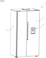
- the refrigerator (1) comprises a body (2) which is suitable for placing the foodstuffs therein; a door (3) which provides access into the body (2); and a water dispenser (4) having a receptacle (5) which is provided on the door (3) and wherein water is stored, a channel (6) which is provided on the lower side of the receptacle (5) and which allows the water to exit the receptacle (5), a spigot (7) which provides the flow of water from the channel (6) and a trigger lever (8) which triggers the movement of the spigot (7).
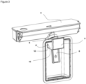
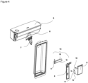
- the refrigerator (1) of the present invention comprises a locking mechanism (14) having a shaft (15), a lock body (16) extending from the shaft (15) and a locking tab (17) attached to at least one end of the shaft (15); a lid (9) having at least one side wall (10) extending towards behind the trigger lever (8) and a first housing (11) which is provided on the side wall (10) so as to remain behind the trigger lever (8) wherein the shaft (15) is fitted; and the locking tab (17) which moves the lock body (16) between the shaft (15) and the trigger lever (8) between a lock position where the lock body (16) almost bears against the trigger lever (8) and a free position where the lock body (16) does not bear against the trigger lever (8)
- the refrigerator (1) of the present invention comprises a lid (9) which covers the claw and mounting mechanisms which enable the trigger lever (8) to be attached to the water dispenser (4) in the form of a cut-out on the door (3) panel
- Said lid (9) comprises at least one side wall (10) so as to cover said connection components located on the upper part of the trigger lever (8).
- the side wall (10) extends to the rear part of the trigger lever (8) where the latter is attached to the door (3).
- the side where the trigger lever (8) is visible through the front panel of the door (3) is the front part of the trigger lever (8). In other words, the part against which the glass is pressed is the front part.
- the side of the trigger lever (8) facing the water dispenser (4) housing on the door (3) panel is the rear part.
- the side wall (10) comprises the first housing (11) so as to remain behind the trigger lever (8).
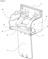
- the refrigerator (1) of the present invention comprises the locking mechanism (14) having a shaft (15), a lock body (16) extending from the shaft (15) and a locking tab (17) providing the horizontal and vertical movement of the lock body (16) with respect to the side wall (10).
- One end of the shaft (15) in said locking mechanism (14) is fitted into the first housing (11) on the side wall (10).
- the shaft (15) is attached to the side wall (10) so as to remain behind the trigger lever (8).
- the locking tab (17) moves the lock body (16) on the side wall (10) with a horizontal-vertical movement of 90 degrees with respect to the side wall (10).
- the lock body (16) is a bar-shaped body extending from the shaft (15). With said movement of the locking tab (17), the lock body (16) switches between a locked position where the lock body (16) almost bears against the rear part of the trigger lever (8) and a free position where the lock body (16) does not bear against the trigger lever (8). The lock body (16) almost bears against the trigger lever (8) so as to push the rear part of the trigger arm (8) in the locked position. Thus, even if the user puts the glass against the front of the trigger lever (8) or applies force by hand, the trigger lever (8) is not triggered to move the spigot (7).
- the refrigerator (1) comprises the lid (9) with a second side wall (20) having a second housing (19) wherein the other end of the shaft (15) is fitted and fixed.
- the second side wall (20) is equivalent to the side wall (10) and extends towards the rear part of the trigger lever (8).
- the second housing (19) is provided on the second side wall (20) in parallel with the first housing (11) so as to remain behind the trigger lever (8).
- the refrigerator (1) comprises the locking mechanism (14) having the lock body (16) with a length at least as much as the width of the trigger lever (8).
- the lock body (16) is as wide as the distance between the rightmost and leftmost ends of the trigger lever (8).
- the refrigerator (1) comprises the locking mechanism (14) having the lock body (16) which extends along the length of the shaft (15).
- the force applied to the trigger lever (8) in the locked position increases and a much stronger pushing force is applied.
- the refrigerator (1) comprises a guide path (12) which is provided on the side wall (10) and which facilitates the movement of the locking tab (17) between the locked position and the free position.
- the guide path (12) is a quadrant-shaped cavity on the side wall (10).
- the refrigerator (1) comprises the locking tab (17) having a protrusion (13) arranged on the guide path (12) and a recess (18) fitted over the protrusion (13) to enable the locking tab (17) to be fixed when the trigger lever (8) is in the free or locked position.
- the locking tab (17) having a protrusion (13) arranged on the guide path (12) and a recess (18) fitted over the protrusion (13) to enable the locking tab (17) to be fixed when the trigger lever (8) is in the free or locked position.
- the refrigerator (1) comprises the locking mechanism (14) having the locking tab (17) with a width equal to that of the lock body (16).
- the lock body (16) and the locking tab (17) have a balanced form, and the user can move the lock body (16) by turning the locking tab (17) without much difficulty.
- the locking tab (17) is equivalent to the cross-section of the lock body (16). For example, if there is a bar-shaped lock body (16) with an oval end, the locking tab (17) has also a rectangular form with an oval end.
- the refrigerator (1) comprises a written and/or illuminated indicator on the side wall (10) showing the locked and free positions of the trigger lever (8).
- the user can quickly realize in which position the trigger lever (8) is left.
Landscapes
- Engineering & Computer Science (AREA)
- Chemical & Material Sciences (AREA)
- Combustion & Propulsion (AREA)
- Physics & Mathematics (AREA)
- Mechanical Engineering (AREA)
- Thermal Sciences (AREA)
- General Engineering & Computer Science (AREA)
- Refrigerator Housings (AREA)
Claims (6)
- Un réfrigérateur (1) comprenant : un corps (2), adapté pour y placer les denrées alimentaires ; une porte (3) qui donne accès à l'intérieur du corps (2) ; un distributeur d'eau (4) ayant un réceptacle (5), disposé sur la porte (3) et dans lequel l'eau est stockée ; un canal (6) qui est disposé sur le côté inférieur du réceptacle (5) et qui permet à l'eau de sortir du réceptacle (5) ; un robinet (7) qui permet l'écoulement de l'eau depuis le canal (6) ; un levier de déclenchement (8) qui déclenche le mouvement du robinet (7) ; un mécanisme de verrouillage (14) comportant un axe (15) ; un corps de verrouillage (16) s'étendant à partir de l'axe (15) ; une languette de verrouillage (17) fixée à au moins une extrémité de l'axe (15) ; un couvercle (9) ayant au moins une paroi latérale (10) s'étendant vers l'arrière du levier de déclenchement (8) ; un premier logement (11) qui est disposé sur la paroi latérale (10) de manière à rester derrière le levier de déclenchement (8) dans lequel l'axe (15) est monté, où la languette de verrouillage (17) déplace le corps de verrouillage (16) entre l'axe (15) et le levier de déclenchement (8) entre une position de verrouillage, où le corps de verrouillage (16) est presque en appui contre le levier de déclenchement (8) et une position libre, où le corps de verrouillage (16) n'est pas en appui contre le levier de déclenchement (8) ; un chemin de guidage (12) qui est disposé sur la paroi latérale (10) et qui facilite le mouvement de la languette de verrouillage (17) entre la position verrouillée et la position libre, caractérisé par la languette de verrouillage (17) qui présente une saillie (13) agencée sur le chemin de guidage (12) et un renfoncement (18) monté sur la saillie (13) pour permettre à la languette de verrouillage (17) d'être fixée lorsque le levier de déclenchement (8) est en position libre ou verrouillée.
- Un réfrigérateur (1) selon la revendication 1, caractérisé par le couvercle (9) qui comporte une deuxième paroi latérale (20) ayant un deuxième logement (19) dans lequel l'autre extrémité de l'axe (15) est montée et fixée.
- Un réfrigérateur (1) selon la revendication 1 ou 2, caractérisé par le mécanisme de verrouillage (14) qui possède un corps de verrouillage (16) d'une longueur au moins égale à la largeur du levier de déclenchement (8).
- Un réfrigérateur (1) selon l'une quelconque des revendications 1 à 3, caractérisé par le mécanisme de verrouillage (14) qui possède un corps de verrouillage (16) qui s'étend sur la longueur de l'axe (15).
- Un réfrigérateur (1) selon l'une quelconque des revendications précédentes, caractérisé par le mécanisme de verrouillage (14) qui possède une languette de verrouillage (17) d'une largeur égale à celle du corps de verrouillage (16).
- Un réfrigérateur (1) selon l'une quelconque des revendications précédentes, caractérisé par un indicateur écrit et/ou lumineux sur la paroi latérale (10) qui montre les positions verrouillée et libre du levier de déclenchement (8).
Applications Claiming Priority (1)
| Application Number | Priority Date | Filing Date | Title |
|---|---|---|---|
| TR202207787 | 2022-05-13 |
Publications (2)
| Publication Number | Publication Date |
|---|---|
| EP4276397A1 EP4276397A1 (fr) | 2023-11-15 |
| EP4276397B1 true EP4276397B1 (fr) | 2024-10-30 |
Family
ID=85792497
Family Applications (1)
| Application Number | Title | Priority Date | Filing Date |
|---|---|---|---|
| EP23165477.3A Active EP4276397B1 (fr) | 2022-05-13 | 2023-03-30 | Réfrigérateur comprenant un distributeur d'eau |
Country Status (2)
| Country | Link |
|---|---|
| EP (1) | EP4276397B1 (fr) |
| PL (1) | PL4276397T3 (fr) |
Family Cites Families (6)
| Publication number | Priority date | Publication date | Assignee | Title |
|---|---|---|---|---|
| KR101817255B1 (ko) | 2011-02-09 | 2018-01-11 | 동부대우전자 주식회사 | 냉장고용 워터 디스펜서의 잠금장치 |
| KR20130053920A (ko) * | 2011-11-16 | 2013-05-24 | 엘지전자 주식회사 | 디스펜서를 구비하는 냉장고 |
| CN103919468B (zh) * | 2013-01-15 | 2016-06-01 | 美的集团股份有限公司 | 防烫水龙头及饮水机 |
| CN105300019A (zh) * | 2015-11-24 | 2016-02-03 | 广东奥马电器股份有限公司 | 一种冰箱用饮水机结构 |
| TR201905011A2 (tr) * | 2019-04-03 | 2020-10-21 | Arcelik As | Su pinari i̇çeren soğutucu ci̇haz |
| CN211582681U (zh) | 2019-11-13 | 2020-09-29 | 广东格兰仕集团有限公司 | 一种冰箱饮水机出水按键的锁止装置 |
-
2023
- 2023-03-30 EP EP23165477.3A patent/EP4276397B1/fr active Active
- 2023-03-30 PL PL23165477.3T patent/PL4276397T3/pl unknown
Also Published As
| Publication number | Publication date |
|---|---|
| EP4276397A1 (fr) | 2023-11-15 |
| PL4276397T3 (pl) | 2025-03-17 |
Similar Documents
| Publication | Publication Date | Title |
|---|---|---|
| US3934757A (en) | Refrigerator water dispenser with child-proof guard | |
| EP1605219B1 (fr) | Distributeur d'eau pour congélateur d'un réfrigérateur | |
| US3858762A (en) | Actuator assembly for an encased dispenser and method | |
| US11828528B2 (en) | Water dispenser | |
| EP3686530B1 (fr) | Réfrigérateur | |
| EP1281346B1 (fr) | Lave-vaiselle avec porte frontale et doseur de détergent qui peut-être rempli par le haut de la porte | |
| WO2008080882A2 (fr) | Réfrigérateur encastré comprenant un distributeur d'eau et de boissons | |
| EP4276397A1 (fr) | Réfrigérateur comprenant un distributeur d'eau | |
| US3286883A (en) | Enclosure and operating mechanism for an aerosol can | |
| CN102224387B (zh) | 制冷装置 | |
| US5970849A (en) | Coffee maker | |
| US20130118203A1 (en) | Refrigerator with dispenser | |
| TR2022007787A2 (tr) | Su pinari i̇çeren bi̇r buzdolabi | |
| US20120248154A1 (en) | Water dispenser faucet actuators | |
| US20250340335A1 (en) | Novel lid assembly | |
| KR200264493Y1 (ko) | 냉장고의도어손잡이겸용디스펜서커버구조 | |
| US20060283867A1 (en) | Disposable beverage container with lid | |
| CN222466665U (zh) | 液体加热容器 | |
| CN218105499U (zh) | 一种滑盖式杯盖以及饮料容器 | |
| JPH0345098Y2 (fr) | ||
| JP3977277B2 (ja) | 貯水器のドレン排出機構 | |
| JPS6112033Y2 (fr) | ||
| KR100238974B1 (ko) | 냉장고 | |
| KR200151245Y1 (ko) | 자동판매기의 동전반환장치 | |
| KR0182547B1 (ko) | 냉장고용 물분배기의 취수장치 |
Legal Events
| Date | Code | Title | Description |
|---|---|---|---|
| PUAI | Public reference made under article 153(3) epc to a published international application that has entered the european phase |
Free format text: ORIGINAL CODE: 0009012 |
|
| STAA | Information on the status of an ep patent application or granted ep patent |
Free format text: STATUS: REQUEST FOR EXAMINATION WAS MADE |
|
| 17P | Request for examination filed |
Effective date: 20230330 |
|
| AK | Designated contracting states |
Kind code of ref document: A1 Designated state(s): AL AT BE BG CH CY CZ DE DK EE ES FI FR GB GR HR HU IE IS IT LI LT LU LV MC ME MK MT NL NO PL PT RO RS SE SI SK SM TR |
|
| GRAP | Despatch of communication of intention to grant a patent |
Free format text: ORIGINAL CODE: EPIDOSNIGR1 |
|
| STAA | Information on the status of an ep patent application or granted ep patent |
Free format text: STATUS: GRANT OF PATENT IS INTENDED |
|
| INTG | Intention to grant announced |
Effective date: 20240626 |
|
| GRAS | Grant fee paid |
Free format text: ORIGINAL CODE: EPIDOSNIGR3 |
|
| GRAA | (expected) grant |
Free format text: ORIGINAL CODE: 0009210 |
|
| STAA | Information on the status of an ep patent application or granted ep patent |
Free format text: STATUS: THE PATENT HAS BEEN GRANTED |
|
| AK | Designated contracting states |
Kind code of ref document: B1 Designated state(s): AL AT BE BG CH CY CZ DE DK EE ES FI FR GB GR HR HU IE IS IT LI LT LU LV MC ME MK MT NL NO PL PT RO RS SE SI SK SM TR |
|
| REG | Reference to a national code |
Ref country code: GB Ref legal event code: FG4D |
|
| REG | Reference to a national code |
Ref country code: CH Ref legal event code: EP |
|
| REG | Reference to a national code |
Ref country code: IE Ref legal event code: FG4D |
|
| REG | Reference to a national code |
Ref country code: DE Ref legal event code: R096 Ref document number: 602023000857 Country of ref document: DE |
|
| REG | Reference to a national code |
Ref country code: LT Ref legal event code: MG9D |
|
| REG | Reference to a national code |
Ref country code: NL Ref legal event code: MP Effective date: 20241030 |
|
| PG25 | Lapsed in a contracting state [announced via postgrant information from national office to epo] |
Ref country code: IS Free format text: LAPSE BECAUSE OF FAILURE TO SUBMIT A TRANSLATION OF THE DESCRIPTION OR TO PAY THE FEE WITHIN THE PRESCRIBED TIME-LIMIT Effective date: 20250228 Ref country code: HR Free format text: LAPSE BECAUSE OF FAILURE TO SUBMIT A TRANSLATION OF THE DESCRIPTION OR TO PAY THE FEE WITHIN THE PRESCRIBED TIME-LIMIT Effective date: 20241030 Ref country code: PT Free format text: LAPSE BECAUSE OF FAILURE TO SUBMIT A TRANSLATION OF THE DESCRIPTION OR TO PAY THE FEE WITHIN THE PRESCRIBED TIME-LIMIT Effective date: 20250228 |
|
| PG25 | Lapsed in a contracting state [announced via postgrant information from national office to epo] |
Ref country code: NL Free format text: LAPSE BECAUSE OF FAILURE TO SUBMIT A TRANSLATION OF THE DESCRIPTION OR TO PAY THE FEE WITHIN THE PRESCRIBED TIME-LIMIT Effective date: 20241030 Ref country code: FI Free format text: LAPSE BECAUSE OF FAILURE TO SUBMIT A TRANSLATION OF THE DESCRIPTION OR TO PAY THE FEE WITHIN THE PRESCRIBED TIME-LIMIT Effective date: 20241030 |
|
| REG | Reference to a national code |
Ref country code: AT Ref legal event code: MK05 Ref document number: 1737230 Country of ref document: AT Kind code of ref document: T Effective date: 20241030 |
|
| PG25 | Lapsed in a contracting state [announced via postgrant information from national office to epo] |
Ref country code: BG Free format text: LAPSE BECAUSE OF FAILURE TO SUBMIT A TRANSLATION OF THE DESCRIPTION OR TO PAY THE FEE WITHIN THE PRESCRIBED TIME-LIMIT Effective date: 20241030 |
|
| PG25 | Lapsed in a contracting state [announced via postgrant information from national office to epo] |
Ref country code: ES Free format text: LAPSE BECAUSE OF FAILURE TO SUBMIT A TRANSLATION OF THE DESCRIPTION OR TO PAY THE FEE WITHIN THE PRESCRIBED TIME-LIMIT Effective date: 20241030 |
|
| PG25 | Lapsed in a contracting state [announced via postgrant information from national office to epo] |
Ref country code: NO Free format text: LAPSE BECAUSE OF FAILURE TO SUBMIT A TRANSLATION OF THE DESCRIPTION OR TO PAY THE FEE WITHIN THE PRESCRIBED TIME-LIMIT Effective date: 20250130 |
|
| PG25 | Lapsed in a contracting state [announced via postgrant information from national office to epo] |
Ref country code: AT Free format text: LAPSE BECAUSE OF FAILURE TO SUBMIT A TRANSLATION OF THE DESCRIPTION OR TO PAY THE FEE WITHIN THE PRESCRIBED TIME-LIMIT Effective date: 20241030 Ref country code: LV Free format text: LAPSE BECAUSE OF FAILURE TO SUBMIT A TRANSLATION OF THE DESCRIPTION OR TO PAY THE FEE WITHIN THE PRESCRIBED TIME-LIMIT Effective date: 20241030 Ref country code: GR Free format text: LAPSE BECAUSE OF FAILURE TO SUBMIT A TRANSLATION OF THE DESCRIPTION OR TO PAY THE FEE WITHIN THE PRESCRIBED TIME-LIMIT Effective date: 20250131 |
|
| PG25 | Lapsed in a contracting state [announced via postgrant information from national office to epo] |
Ref country code: RS Free format text: LAPSE BECAUSE OF FAILURE TO SUBMIT A TRANSLATION OF THE DESCRIPTION OR TO PAY THE FEE WITHIN THE PRESCRIBED TIME-LIMIT Effective date: 20250130 |
|
| PG25 | Lapsed in a contracting state [announced via postgrant information from national office to epo] |
Ref country code: SM Free format text: LAPSE BECAUSE OF FAILURE TO SUBMIT A TRANSLATION OF THE DESCRIPTION OR TO PAY THE FEE WITHIN THE PRESCRIBED TIME-LIMIT Effective date: 20241030 |
|
| PG25 | Lapsed in a contracting state [announced via postgrant information from national office to epo] |
Ref country code: DK Free format text: LAPSE BECAUSE OF FAILURE TO SUBMIT A TRANSLATION OF THE DESCRIPTION OR TO PAY THE FEE WITHIN THE PRESCRIBED TIME-LIMIT Effective date: 20241030 |
|
| PG25 | Lapsed in a contracting state [announced via postgrant information from national office to epo] |
Ref country code: EE Free format text: LAPSE BECAUSE OF FAILURE TO SUBMIT A TRANSLATION OF THE DESCRIPTION OR TO PAY THE FEE WITHIN THE PRESCRIBED TIME-LIMIT Effective date: 20241030 |
|
| PG25 | Lapsed in a contracting state [announced via postgrant information from national office to epo] |
Ref country code: RO Free format text: LAPSE BECAUSE OF FAILURE TO SUBMIT A TRANSLATION OF THE DESCRIPTION OR TO PAY THE FEE WITHIN THE PRESCRIBED TIME-LIMIT Effective date: 20241030 |
|
| PG25 | Lapsed in a contracting state [announced via postgrant information from national office to epo] |
Ref country code: SK Free format text: LAPSE BECAUSE OF FAILURE TO SUBMIT A TRANSLATION OF THE DESCRIPTION OR TO PAY THE FEE WITHIN THE PRESCRIBED TIME-LIMIT Effective date: 20241030 |
|
| PG25 | Lapsed in a contracting state [announced via postgrant information from national office to epo] |
Ref country code: CZ Free format text: LAPSE BECAUSE OF FAILURE TO SUBMIT A TRANSLATION OF THE DESCRIPTION OR TO PAY THE FEE WITHIN THE PRESCRIBED TIME-LIMIT Effective date: 20241030 |
|
| PG25 | Lapsed in a contracting state [announced via postgrant information from national office to epo] |
Ref country code: IT Free format text: LAPSE BECAUSE OF FAILURE TO SUBMIT A TRANSLATION OF THE DESCRIPTION OR TO PAY THE FEE WITHIN THE PRESCRIBED TIME-LIMIT Effective date: 20241030 |
|
| REG | Reference to a national code |
Ref country code: DE Ref legal event code: R097 Ref document number: 602023000857 Country of ref document: DE |
|
| PLBE | No opposition filed within time limit |
Free format text: ORIGINAL CODE: 0009261 |
|
| STAA | Information on the status of an ep patent application or granted ep patent |
Free format text: STATUS: NO OPPOSITION FILED WITHIN TIME LIMIT |
|
| PG25 | Lapsed in a contracting state [announced via postgrant information from national office to epo] |
Ref country code: SE Free format text: LAPSE BECAUSE OF FAILURE TO SUBMIT A TRANSLATION OF THE DESCRIPTION OR TO PAY THE FEE WITHIN THE PRESCRIBED TIME-LIMIT Effective date: 20241030 |
|
| 26N | No opposition filed |
Effective date: 20250731 |
|
| PG25 | Lapsed in a contracting state [announced via postgrant information from national office to epo] |
Ref country code: MC Free format text: LAPSE BECAUSE OF FAILURE TO SUBMIT A TRANSLATION OF THE DESCRIPTION OR TO PAY THE FEE WITHIN THE PRESCRIBED TIME-LIMIT Effective date: 20241030 |
|
| PG25 | Lapsed in a contracting state [announced via postgrant information from national office to epo] |
Ref country code: LU Free format text: LAPSE BECAUSE OF NON-PAYMENT OF DUE FEES Effective date: 20250330 |
|
| REG | Reference to a national code |
Ref country code: BE Ref legal event code: MM Effective date: 20250331 |
|
| PG25 | Lapsed in a contracting state [announced via postgrant information from national office to epo] |
Ref country code: BE Free format text: LAPSE BECAUSE OF NON-PAYMENT OF DUE FEES Effective date: 20250331 |
|
| PG25 | Lapsed in a contracting state [announced via postgrant information from national office to epo] |
Ref country code: IE Free format text: LAPSE BECAUSE OF NON-PAYMENT OF DUE FEES Effective date: 20250330 |
|
| PGFP | Annual fee paid to national office [announced via postgrant information from national office to epo] |
Ref country code: DE Payment date: 20260319 Year of fee payment: 4 |
|
| PGFP | Annual fee paid to national office [announced via postgrant information from national office to epo] |
Ref country code: FR Payment date: 20260323 Year of fee payment: 4 |
|
| PGFP | Annual fee paid to national office [announced via postgrant information from national office to epo] |
Ref country code: TR Payment date: 20260306 Year of fee payment: 4 |
|
| PGFP | Annual fee paid to national office [announced via postgrant information from national office to epo] |
Ref country code: PL Payment date: 20260319 Year of fee payment: 4 |