EP4276397A1 - A refrigerator comprising a water dispenser - Google Patents
A refrigerator comprising a water dispenser Download PDFInfo
- Publication number
- EP4276397A1 EP4276397A1 EP23165477.3A EP23165477A EP4276397A1 EP 4276397 A1 EP4276397 A1 EP 4276397A1 EP 23165477 A EP23165477 A EP 23165477A EP 4276397 A1 EP4276397 A1 EP 4276397A1
- Authority
- EP
- European Patent Office
- Prior art keywords
- trigger lever
- refrigerator
- shaft
- lock body
- side wall
- Prior art date
- Legal status (The legal status is an assumption and is not a legal conclusion. Google has not performed a legal analysis and makes no representation as to the accuracy of the status listed.)
- Granted
Links
Images




Classifications
-
- F—MECHANICAL ENGINEERING; LIGHTING; HEATING; WEAPONS; BLASTING
- F25—REFRIGERATION OR COOLING; COMBINED HEATING AND REFRIGERATION SYSTEMS; HEAT PUMP SYSTEMS; MANUFACTURE OR STORAGE OF ICE; LIQUEFACTION SOLIDIFICATION OF GASES
- F25D—REFRIGERATORS; COLD ROOMS; ICE-BOXES; COOLING OR FREEZING APPARATUS NOT OTHERWISE PROVIDED FOR
- F25D23/00—General constructional features
- F25D23/12—Arrangements of compartments additional to cooling compartments; Combinations of refrigerators with other equipment, e.g. stove
- F25D23/126—Water cooler
-
- F—MECHANICAL ENGINEERING; LIGHTING; HEATING; WEAPONS; BLASTING
- F25—REFRIGERATION OR COOLING; COMBINED HEATING AND REFRIGERATION SYSTEMS; HEAT PUMP SYSTEMS; MANUFACTURE OR STORAGE OF ICE; LIQUEFACTION SOLIDIFICATION OF GASES
- F25D—REFRIGERATORS; COLD ROOMS; ICE-BOXES; COOLING OR FREEZING APPARATUS NOT OTHERWISE PROVIDED FOR
- F25D2323/00—General constructional features not provided for in other groups of this subclass
- F25D2323/122—General constructional features not provided for in other groups of this subclass the refrigerator is characterised by a water tank for the water/ice dispenser
Definitions
- the present invention relates to a water dispenser lock, especially the lock of the trigger lever of the water dispenser in a refrigerator.
- Refrigerators with water dispensers mounted on the door which store cold drinking water for the user are widely known in the art.
- Said refrigerators comprise a water dispenser area in the form of a cut-out in the door panel.
- the connection and mounting parts at the top of the trigger lever in the dispenser mechanism of the water dispenser are covered with a lid, and by means of a spigot which is triggered by pressing a glass on the exposed part of the trigger lever or by applying an appropriate force, the water in the water tank is enabled to be filled into the glass, etc.
- Said refrigerators having a water dispenser are preferred especially in summer months to meet the cold water needs of users.
- the trigger lever is easily pushed back by pressing a filling container such as a glass thereon, and water is filled into the glass.
- the trigger lever can also be easily pushed by hand without the need to pressing with a glass, and if there is no locking mechanism, may cause water to spill. This situation creates problems especially for children's access. Children may constantly press the trigger lever, causing the water to spill and the surroundings to get wet. Therefore, the users especially prefer a lock structure in the water dispensers.
- a water dispenser lock mechanism comprising a stopper disposed between two arms.
- a water dispenser lock structure comprising a sliding mechanism, an opening and a stopper which is disposed on the sliding mechanism.
- the state of the art water dispenser locks break down after a certain period of time due to their complex structure, and especially the sliding and multi-part locks break down after a while and become inoperable.
- the aim of the present invention is the realization of a refrigerator wherein the water dispenser trigger lever is locked by means of a practical and simple mechanism.
- Another aim of the present invention is the realization of a refrigerator comprising a water dispenser wherein the locked and free position of the trigger lever can be easily seen and adjusted through the refrigerator door.
- the refrigerator of the present invention comprises a trigger lever which enables the spigot on the water dispenser to be moved between an open position and a closed position and which triggers the emptying of the water from the receptacle.
- the trigger lever comprises mounting components on the upper side thereof used for being mounted to the water dispenser.
- the surface of the trigger lever which is pressed by a glass, etc. is the front surface thereof.
- the surface facing the water dispenser housing is the rear surface.
- a lid having at least one side wall which leaves the trigger lever open, but covers the upper region which is the mounting part of the trigger lever. Said side wall extends towards the rear side of the trigger lever and comprises a first housing thereon.
- the refrigerator of the present invention comprises a locking mechanism having a shaft, a lock body in the form of a bar extending from the shaft, and a locking tab which enables the lock body to be rotated around the shaft and which is connected to at least one end of the shaft.
- the shaft and the lock body can be a single piece or separate pieces which can be assembled.
- the end of said shaft in contact with the locking tab is attached to the first housing on the side wall.
- the locking mechanism is positioned behind the trigger lever.
- the lock body is preferably a bar-shaped body which extends between the shaft and the rear part of the trigger lever in the lock position of the trigger lever and which has a width that can push the trigger lever.
- the refrigerator (1) comprises a body (2) which is suitable for placing the foodstuffs therein; a door (3) which provides access into the body (2); and a water dispenser (4) having a receptacle (5) which is provided on the door (3) and wherein water is stored, a channel (6) which is provided on the lower side of the receptacle (5) and which allows the water to exit the receptacle (5), a spigot (7) which provides the flow of water from the channel (6) and a trigger lever (8) which triggers the movement of the spigot (7).
- the refrigerator (1) of the present invention comprises a locking mechanism (14) having a shaft (15), a lock body (16) extending from the shaft (15) and a locking tab (17) attached to at least one end of the shaft (15); a lid (9) having at least one side wall (10) extending towards behind the trigger lever (8) and a first housing (11) which is provided on the side wall (10) so as to remain behind the trigger lever (8) wherein the shaft (15) is fitted; and the locking tab (17) which moves the lock body (16) between the shaft (15) and the trigger lever (8) between a lock position where the lock body (16) almost bears against the trigger lever (8) and a free position where the lock body (16) does not bear against the trigger lever (8)
- the refrigerator (1) of the present invention comprises a lid (9) which covers the claw and mounting mechanisms which enable the trigger lever (8) to be attached to the water dispenser (4) in the form of a cut-out on the door (3) panel
- Said lid (9) comprises at least one side wall (10) so as to cover said connection components located on the upper part of the trigger lever (8).
- the side wall (10) extends to the rear part of the trigger lever (8) where the latter is attached to the door (3).
- the side where the trigger lever (8) is visible through the front panel of the door (3) is the front part of the trigger lever (8). In other words, the part against which the glass is pressed is the front part.
- the side of the trigger lever (8) facing the water dispenser (4) housing on the door (3) panel is the rear part.
- the side wall (10) comprises the first housing (11) so as to remain behind the trigger lever (8).
- the refrigerator (1) of the present invention comprises the locking mechanism (14) having a shaft (15), a lock body (16) extending from the shaft (15) and a locking tab (17) providing the horizontal and vertical movement of the lock body (16) with respect to the side wall (10).
- One end of the shaft (15) in said locking mechanism (14) is fitted into the first housing (11) on the side wall (10).
- the shaft (15) is attached to the side wall (10) so as to remain behind the trigger lever (8).
- the locking tab (17) moves the lock body (16) on the side wall (10) with a horizontal-vertical movement of 90 degrees with respect to the side wall (10).
- the lock body (16) is a bar-shaped body extending from the shaft (15). With said movement of the locking tab (17), the lock body (16) switches between a locked position where the lock body (16) almost bears against the rear part of the trigger lever (8) and a free position where the lock body (16) does not bear against the trigger lever (8). The lock body (16) almost bears against the trigger lever (8) so as to push the rear part of the trigger arm (8) in the locked position. Thus, even if the user puts the glass against the front of the trigger lever (8) or applies force by hand, the trigger lever (8) is not triggered to move the spigot (7).
- the refrigerator (1) comprises the lid (9) with a second side wall (20) having a second housing (19) wherein the other end of the shaft (15) is fitted and fixed.
- the second side wall (20) is equivalent to the side wall (10) and extends towards the rear part of the trigger lever (8).
- the second housing (19) is provided on the second side wall (20) in parallel with the first housing (11) so as to remain behind the trigger lever (8).
- the refrigerator (1) comprises a locking mechanism (14) having the lock body (16) with a length at least as much as the width of the trigger lever (8).
- the lock body (16) is as wide as the distance between the rightmost and leftmost ends of the trigger lever (8).
- the refrigerator (1) comprises a locking mechanism (14) having the lock body (16) which extends along the length of the shaft (15).
- the force applied to the trigger lever (8) in the locked position increases and a much stronger pushing force is applied.
- the refrigerator (1) comprises a guide path (12) which is provided on the side wall (10) and which facilitates the movement of the locking tab (17) between the locked position and the free position.
- the guide path (12) is a quadrant-shaped cavity on the side wall (10).
- the refrigerator (1) comprises the locking tab (17) having a protrusion (13) arranged on the guide path (12) and a recess (18) fitted over the protrusion (13) to enable the locking tab (17) to be fixed when the trigger lever (8) is in the free or locked position.
- the locking tab (17) having a protrusion (13) arranged on the guide path (12) and a recess (18) fitted over the protrusion (13) to enable the locking tab (17) to be fixed when the trigger lever (8) is in the free or locked position.
- the refrigerator (1) comprises the locking mechanism (14) having a locking tab (17) with a width equal to that of the lock body (16).
- the lock body (16) and the locking tab (17) have a balanced form, and the user can move the lock body (16) by turning the locking tab (17) without much difficulty.
- the locking tab (17) is equivalent to the cross-section of the lock body (16). For example, if there is a bar-shaped lock body (16) with an oval end, the locking tab (17) has also a rectangular form with an oval end.
- the refrigerator (1) comprises a written and/or illuminated indicator on the side wall (10) showing the locked and free positions of the trigger lever (8).
- the user can quickly realize in which position the trigger lever (8) is left.
Landscapes
- Engineering & Computer Science (AREA)
- Chemical & Material Sciences (AREA)
- Combustion & Propulsion (AREA)
- Physics & Mathematics (AREA)
- Mechanical Engineering (AREA)
- Thermal Sciences (AREA)
- General Engineering & Computer Science (AREA)
- Refrigerator Housings (AREA)
Abstract
Description
- The present invention relates to a water dispenser lock, especially the lock of the trigger lever of the water dispenser in a refrigerator.
- Refrigerators with water dispensers mounted on the door which store cold drinking water for the user are widely known in the art. Said refrigerators comprise a water dispenser area in the form of a cut-out in the door panel. The connection and mounting parts at the top of the trigger lever in the dispenser mechanism of the water dispenser are covered with a lid, and by means of a spigot which is triggered by pressing a glass on the exposed part of the trigger lever or by applying an appropriate force, the water in the water tank is enabled to be filled into the glass, etc.
- Said refrigerators having a water dispenser are preferred especially in summer months to meet the cold water needs of users. The trigger lever is easily pushed back by pressing a filling container such as a glass thereon, and water is filled into the glass. The trigger lever can also be easily pushed by hand without the need to pressing with a glass, and if there is no locking mechanism, may cause water to spill. This situation creates problems especially for children's access. Children may constantly press the trigger lever, causing the water to spill and the surroundings to get wet. Therefore, the users especially prefer a lock structure in the water dispensers.
- Many types of child lock structures are known in the refrigerators having a water dispenser or in the standalone water dispensers. The aim of all these locks is to ensure that water is taken from the water dispenser in a controlled manner, especially to prevent children from operating the water dispenser outside of parental control.
- In the state of the art Korean Patent Document No.
KR20120091532 - In the state of the art Chinese Utility Model Document No.
CN211582681U , a water dispenser lock structure is disclosed, comprising a sliding mechanism, an opening and a stopper which is disposed on the sliding mechanism. - The state of the art water dispenser locks break down after a certain period of time due to their complex structure, and especially the sliding and multi-part locks break down after a while and become inoperable.
- The aim of the present invention is the realization of a refrigerator wherein the water dispenser trigger lever is locked by means of a practical and simple mechanism.
- Another aim of the present invention is the realization of a refrigerator comprising a water dispenser wherein the locked and free position of the trigger lever can be easily seen and adjusted through the refrigerator door.
- The refrigerator of the present invention comprises a trigger lever which enables the spigot on the water dispenser to be moved between an open position and a closed position and which triggers the emptying of the water from the receptacle. The trigger lever comprises mounting components on the upper side thereof used for being mounted to the water dispenser. The surface of the trigger lever which is pressed by a glass, etc. is the front surface thereof. The surface facing the water dispenser housing is the rear surface.
- In the present invention, there is a lid having at least one side wall which leaves the trigger lever open, but covers the upper region which is the mounting part of the trigger lever. Said side wall extends towards the rear side of the trigger lever and comprises a first housing thereon.
- The refrigerator of the present invention, comprises a locking mechanism having a shaft, a lock body in the form of a bar extending from the shaft, and a locking tab which enables the lock body to be rotated around the shaft and which is connected to at least one end of the shaft.
- In an embodiment of the present invention, the shaft and the lock body can be a single piece or separate pieces which can be assembled.
- The end of said shaft in contact with the locking tab is attached to the first housing on the side wall. Thus, the locking mechanism is positioned behind the trigger lever. The lock body is preferably a bar-shaped body which extends between the shaft and the rear part of the trigger lever in the lock position of the trigger lever and which has a width that can push the trigger lever.
- By means of the present invention, a water dispenser having a practical child lock mechanism and a refrigerator comprising the water dispenser are realized.
- Additional features and additional advantageous effects of the water dispenser lock of the present invention and the refrigerator of the present invention will become more apparent with the detailed description of the embodiments with reference to the accompanying drawings in which: Said figures are:
-
Figure 1 : is the perspective view of the refrigerator comprising a water dispenser having a locking mechanism in an embodiment of the present invention. -
Figure 2 : is the exploded view showing the door, the water dispenser and the trigger unit in an embodiment of the present invention. -
Figure 3 : is the perspective view of the assembled state of the water dispenser and the receptacle in an embodiment of the present invention. -
Figure 4 : is the exploded view ofFigure 3 . -
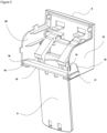
Figure 5 : is the view showing the rear side of the trigger lever and the locked position of the locking mechanism in an embodiment of the present invention. -
Figure 6 : is the view showing the components of the locking mechanism in an embodiment of the present invention. -
Figure 7 : is the sideways view showing the state where the locking tab moves the trigger lever to the free position in an embodiment of the present invention. -
Figure 8 : is the sideways view showing the state where the locking tab moves the trigger lever to the locked position in an embodiment of the present invention. - The following numerals are referred to in the description of the present invention:
- 1.
- Refrigerator
- 2.
- Body
- 3.
- Door
- 4.
- Water dispenser
- 5.
- Receptacle
- 6.
- Channel
- 7.
- Spigot
- 8.
- Trigger lever
- 9.
- Lid
- 10.
- Side wall
- 11.
- First housing
- 12.
- Guide path
- 13.
- Protrusion
- 14.
- Locking mechanism
- 15.
- Shaft
- 16.
- Lock body
- 17.
- Locking tab
- 18.
- Recess
- 19.
- Second housing
- 20.
- Second side wall
- The refrigerator (1) comprises a body (2) which is suitable for placing the foodstuffs therein; a door (3) which provides access into the body (2); and a water dispenser (4) having a receptacle (5) which is provided on the door (3) and wherein water is stored, a channel (6) which is provided on the lower side of the receptacle (5) and which allows the water to exit the receptacle (5), a spigot (7) which provides the flow of water from the channel (6) and a trigger lever (8) which triggers the movement of the spigot (7).
- The refrigerator (1) of the present invention comprises a locking mechanism (14) having a shaft (15), a lock body (16) extending from the shaft (15) and a locking tab (17) attached to at least one end of the shaft (15); a lid (9) having at least one side wall (10) extending towards behind the trigger lever (8) and a first housing (11) which is provided on the side wall (10) so as to remain behind the trigger lever (8) wherein the shaft (15) is fitted; and the locking tab (17) which moves the lock body (16) between the shaft (15) and the trigger lever (8) between a lock position where the lock body (16) almost bears against the trigger lever (8) and a free position where the lock body (16) does not bear against the trigger lever (8)
- The refrigerator (1) of the present invention comprises a lid (9) which covers the claw and mounting mechanisms which enable the trigger lever (8) to be attached to the water dispenser (4) in the form of a cut-out on the door (3) panel Said lid (9) comprises at least one side wall (10) so as to cover said connection components located on the upper part of the trigger lever (8). The side wall (10) extends to the rear part of the trigger lever (8) where the latter is attached to the door (3). The side where the trigger lever (8) is visible through the front panel of the door (3) is the front part of the trigger lever (8). In other words, the part against which the glass is pressed is the front part. The side of the trigger lever (8) facing the water dispenser (4) housing on the door (3) panel is the rear part. The side wall (10) comprises the first housing (11) so as to remain behind the trigger lever (8). The refrigerator (1) of the present invention comprises the locking mechanism (14) having a shaft (15), a lock body (16) extending from the shaft (15) and a locking tab (17) providing the horizontal and vertical movement of the lock body (16) with respect to the side wall (10). One end of the shaft (15) in said locking mechanism (14) is fitted into the first housing (11) on the side wall (10). Thus, the shaft (15) is attached to the side wall (10) so as to remain behind the trigger lever (8). At the end of the shaft (15), which is fitted into the first housing (11), there is a locking tab (17) in connection with the shaft (15). The locking tab (17) moves the lock body (16) on the side wall (10) with a horizontal-vertical movement of 90 degrees with respect to the side wall (10). The lock body (16) is a bar-shaped body extending from the shaft (15). With said movement of the locking tab (17), the lock body (16) switches between a locked position where the lock body (16) almost bears against the rear part of the trigger lever (8) and a free position where the lock body (16) does not bear against the trigger lever (8). The lock body (16) almost bears against the trigger lever (8) so as to push the rear part of the trigger arm (8) in the locked position. Thus, even if the user puts the glass against the front of the trigger lever (8) or applies force by hand, the trigger lever (8) is not triggered to move the spigot (7).
- In an embodiment of the present invention, the refrigerator (1) comprises the lid (9) with a second side wall (20) having a second housing (19) wherein the other end of the shaft (15) is fitted and fixed. Thus, since the other end of the shaft (15) is fixed to the second side wall (20), a much stronger locking is achieved. The second side wall (20) is equivalent to the side wall (10) and extends towards the rear part of the trigger lever (8). The second housing (19) is provided on the second side wall (20) in parallel with the first housing (11) so as to remain behind the trigger lever (8).
- In an embodiment of the present invention, the refrigerator (1) comprises a locking mechanism (14) having the lock body (16) with a length at least as much as the width of the trigger lever (8). In this embodiment, the lock body (16) is as wide as the distance between the rightmost and leftmost ends of the trigger lever (8). Thus, the minimum force required to push the trigger lever (8) is easily applied when the locking tab (17) is rotated in the locked position.
- In an embodiment of the present invention, the refrigerator (1) comprises a locking mechanism (14) having the lock body (16) which extends along the length of the shaft (15). Thus, the force applied to the trigger lever (8) in the locked position increases and a much stronger pushing force is applied.
- In an embodiment of the present invention, the refrigerator (1) comprises a guide path (12) which is provided on the side wall (10) and which facilitates the movement of the locking tab (17) between the locked position and the free position. In one embodiment, the guide path (12) is a quadrant-shaped cavity on the side wall (10). Thus, the locking tab (17) is easily slid and moved between the locked position and the free position in the guide path (12).
- In an embodiment of the present invention, the refrigerator (1) comprises the locking tab (17) having a protrusion (13) arranged on the guide path (12) and a recess (18) fitted over the protrusion (13) to enable the locking tab (17) to be fixed when the trigger lever (8) is in the free or locked position. Thus, if the user wants the trigger lever (8) to remain in the free position, he/she can shift the locking mechanism (14) to the passive position. On the contrary, if the user wants to keep the trigger lever (8) in the locked position all the time, he/she leaves the locking mechanism (14) in the active position.
- In an embodiment of the present invention, the refrigerator (1) comprises the locking mechanism (14) having a locking tab (17) with a width equal to that of the lock body (16). Thus, the lock body (16) and the locking tab (17) have a balanced form, and the user can move the lock body (16) by turning the locking tab (17) without much difficulty. In an embodiment of the present invention, the locking tab (17) is equivalent to the cross-section of the lock body (16). For example, if there is a bar-shaped lock body (16) with an oval end, the locking tab (17) has also a rectangular form with an oval end.
- In an embodiment of the present invention, the refrigerator (1) comprises a written and/or illuminated indicator on the side wall (10) showing the locked and free positions of the trigger lever (8). Thus, the user can quickly realize in which position the trigger lever (8) is left.
Claims (8)
- A refrigerator (1) comprising a body (2) which is suitable for placing the foodstuffs therein; a door (3) which provides access into the body (2); and a water dispenser (4) having a receptacle (5) which is provided on the door (3) and wherein water is stored, a channel (6) which is provided on the lower side of the receptacle (5) and which allows the water to exit the receptacle (5), a spigot (7) which provides the flow of water from the channel (6) and a trigger lever (8) which triggers the movement of the spigot (7), characterized by a locking mechanism (14) having a shaft (15), a lock body (16) extending from the shaft (15) and a locking tab (17) attached to at least one end of the shaft (15); a lid (9) having at least one side wall (10) extending towards behind the trigger lever (8) and a first housing (11) which is provided on the side wall (10) so as to remain behind the trigger lever (8) wherein the shaft (15) is fitted; and the locking tab (17) which moves the lock body (16) between the shaft (15) and the trigger lever (8) between a lock position where the lock body (16) almost bears against the trigger lever (8) and a free position where the lock body (16) does not bear against the trigger lever (8)
- A refrigerator (1) as in Claim 1, characterized by the lid (9) with a second side wall (20) having a second housing (19) wherein the other end of the shaft (15) is fitted and fixed.
- A refrigerator (1) as in Claim 1 or 2, characterized by a locking mechanism (14) having the lock body (16) with a length at least as much as the width of the trigger lever (8).
- A refrigerator (1) as in any one of Claims 1 to 3, characterized by a locking mechanism (14) having the lock body (16) which extends along the length of the shaft (15).
- A refrigerator (1) as in any one of Claims 1 to 4, characterized by a guide path (12) which is provided on the side wall (10) and which facilitates the movement of the locking tab (17) between the locked position and the free position.
- A refrigerator (1) as in Claim 5, characterized by the locking tab (17) having a protrusion (13) arranged on the guide path (12) and a recess (18) fitted over the protrusion (13) to enable the locking tab (17) to be fixed when the trigger lever (8) is in the free or locked position.
- A refrigerator (1) as in any one of the above claims, characterized by the locking mechanism (14) having a locking tab (17) with a width equal to that of the lock body (16).
- A refrigerator (1) as in any one of the above claims, characterized by a written and/or illuminated indicator on the side wall (10) showing the locked and free positions of the trigger lever (8).
Applications Claiming Priority (1)
| Application Number | Priority Date | Filing Date | Title |
|---|---|---|---|
| TR202207787 | 2022-05-13 |
Publications (2)
| Publication Number | Publication Date |
|---|---|
| EP4276397A1 true EP4276397A1 (en) | 2023-11-15 |
| EP4276397B1 EP4276397B1 (en) | 2024-10-30 |
Family
ID=85792497
Family Applications (1)
| Application Number | Title | Priority Date | Filing Date |
|---|---|---|---|
| EP23165477.3A Active EP4276397B1 (en) | 2022-05-13 | 2023-03-30 | A refrigerator comprising a water dispenser |
Country Status (2)
| Country | Link |
|---|---|
| EP (1) | EP4276397B1 (en) |
| PL (1) | PL4276397T3 (en) |
Citations (6)
| Publication number | Priority date | Publication date | Assignee | Title |
|---|---|---|---|---|
| KR20120091532A (en) | 2011-02-09 | 2012-08-20 | 주식회사 대우일렉트로닉스 | Locking device of water dispenser for refrigerator |
| US20130118203A1 (en) * | 2011-11-16 | 2013-05-16 | Lg Electronics Inc. | Refrigerator with dispenser |
| CN103919468A (en) * | 2013-01-15 | 2014-07-16 | 美的集团股份有限公司 | Anti-scald faucet and water dispenser |
| CN105300019A (en) * | 2015-11-24 | 2016-02-03 | 广东奥马电器股份有限公司 | Water dispenser structure for refrigerator |
| CN211582681U (en) | 2019-11-13 | 2020-09-29 | 广东格兰仕集团有限公司 | Locking device of water outlet button of refrigerator water dispenser |
| WO2020200581A1 (en) * | 2019-04-03 | 2020-10-08 | Arcelik Anonim Sirketi | A cooling appliance having a water dispenser |
-
2023
- 2023-03-30 EP EP23165477.3A patent/EP4276397B1/en active Active
- 2023-03-30 PL PL23165477.3T patent/PL4276397T3/en unknown
Patent Citations (6)
| Publication number | Priority date | Publication date | Assignee | Title |
|---|---|---|---|---|
| KR20120091532A (en) | 2011-02-09 | 2012-08-20 | 주식회사 대우일렉트로닉스 | Locking device of water dispenser for refrigerator |
| US20130118203A1 (en) * | 2011-11-16 | 2013-05-16 | Lg Electronics Inc. | Refrigerator with dispenser |
| CN103919468A (en) * | 2013-01-15 | 2014-07-16 | 美的集团股份有限公司 | Anti-scald faucet and water dispenser |
| CN105300019A (en) * | 2015-11-24 | 2016-02-03 | 广东奥马电器股份有限公司 | Water dispenser structure for refrigerator |
| WO2020200581A1 (en) * | 2019-04-03 | 2020-10-08 | Arcelik Anonim Sirketi | A cooling appliance having a water dispenser |
| CN211582681U (en) | 2019-11-13 | 2020-09-29 | 广东格兰仕集团有限公司 | Locking device of water outlet button of refrigerator water dispenser |
Also Published As
| Publication number | Publication date |
|---|---|
| EP4276397B1 (en) | 2024-10-30 |
| PL4276397T3 (en) | 2025-03-17 |
Similar Documents
| Publication | Publication Date | Title |
|---|---|---|
| US3934757A (en) | Refrigerator water dispenser with child-proof guard | |
| EP3686530B1 (en) | Refrigerator | |
| US7188487B2 (en) | Dispenser for refrigerator | |
| EP1281346B1 (en) | Domestic dishwasher with a front door and a detergent measurer which can be refilled on the top of the door | |
| EP4276397B1 (en) | A refrigerator comprising a water dispenser | |
| CN102224387B (en) | Refrigeration device | |
| US3286883A (en) | Enclosure and operating mechanism for an aerosol can | |
| GB1450657A (en) | Toilet cabinet especially for hospitals | |
| TR2022007787A2 (en) | A REFRIGERATOR WITH A WATER DISPENSER | |
| US20130118203A1 (en) | Refrigerator with dispenser | |
| KR200151245Y1 (en) | Coin Return Device for Vending Machine | |
| US20040055913A1 (en) | Casing for an electric appliance and an electric appliance with such a casing | |
| JPS5813406Y2 (en) | Vending machine return gate device | |
| KR101221763B1 (en) | A structure for mounting the operational lever in refrigerator | |
| KR200264493Y1 (en) | Dispenser cover structure for door handle of refrigerator | |
| JPH0415160Y2 (en) | ||
| KR101281503B1 (en) | Sub-shelf for furniture | |
| KR920000012Y1 (en) | Door lock for cabinet | |
| KR0125603Y1 (en) | Device for fixing a refrigerator's door | |
| KR100238974B1 (en) | Refrigerator | |
| KR19990035796U (en) | Automatic Drinking Device of Drink Vending Machine | |
| JPH0538645Y2 (en) | ||
| JPH0335747Y2 (en) | ||
| KR920001872Y1 (en) | Door lock | |
| EP3390752B1 (en) | Piece of furniture with improved handle |
Legal Events
| Date | Code | Title | Description |
|---|---|---|---|
| PUAI | Public reference made under article 153(3) epc to a published international application that has entered the european phase |
Free format text: ORIGINAL CODE: 0009012 |
|
| STAA | Information on the status of an ep patent application or granted ep patent |
Free format text: STATUS: REQUEST FOR EXAMINATION WAS MADE |
|
| 17P | Request for examination filed |
Effective date: 20230330 |
|
| AK | Designated contracting states |
Kind code of ref document: A1 Designated state(s): AL AT BE BG CH CY CZ DE DK EE ES FI FR GB GR HR HU IE IS IT LI LT LU LV MC ME MK MT NL NO PL PT RO RS SE SI SK SM TR |
|
| GRAP | Despatch of communication of intention to grant a patent |
Free format text: ORIGINAL CODE: EPIDOSNIGR1 |
|
| STAA | Information on the status of an ep patent application or granted ep patent |
Free format text: STATUS: GRANT OF PATENT IS INTENDED |
|
| INTG | Intention to grant announced |
Effective date: 20240626 |
|
| GRAS | Grant fee paid |
Free format text: ORIGINAL CODE: EPIDOSNIGR3 |
|
| GRAA | (expected) grant |
Free format text: ORIGINAL CODE: 0009210 |
|
| STAA | Information on the status of an ep patent application or granted ep patent |
Free format text: STATUS: THE PATENT HAS BEEN GRANTED |
|
| AK | Designated contracting states |
Kind code of ref document: B1 Designated state(s): AL AT BE BG CH CY CZ DE DK EE ES FI FR GB GR HR HU IE IS IT LI LT LU LV MC ME MK MT NL NO PL PT RO RS SE SI SK SM TR |
|
| REG | Reference to a national code |
Ref country code: GB Ref legal event code: FG4D |
|
| REG | Reference to a national code |
Ref country code: CH Ref legal event code: EP |
|
| REG | Reference to a national code |
Ref country code: IE Ref legal event code: FG4D |
|
| REG | Reference to a national code |
Ref country code: DE Ref legal event code: R096 Ref document number: 602023000857 Country of ref document: DE |
|
| REG | Reference to a national code |
Ref country code: LT Ref legal event code: MG9D |
|
| REG | Reference to a national code |
Ref country code: NL Ref legal event code: MP Effective date: 20241030 |
|
| PG25 | Lapsed in a contracting state [announced via postgrant information from national office to epo] |
Ref country code: IS Free format text: LAPSE BECAUSE OF FAILURE TO SUBMIT A TRANSLATION OF THE DESCRIPTION OR TO PAY THE FEE WITHIN THE PRESCRIBED TIME-LIMIT Effective date: 20250228 Ref country code: HR Free format text: LAPSE BECAUSE OF FAILURE TO SUBMIT A TRANSLATION OF THE DESCRIPTION OR TO PAY THE FEE WITHIN THE PRESCRIBED TIME-LIMIT Effective date: 20241030 Ref country code: PT Free format text: LAPSE BECAUSE OF FAILURE TO SUBMIT A TRANSLATION OF THE DESCRIPTION OR TO PAY THE FEE WITHIN THE PRESCRIBED TIME-LIMIT Effective date: 20250228 |
|
| PG25 | Lapsed in a contracting state [announced via postgrant information from national office to epo] |
Ref country code: NL Free format text: LAPSE BECAUSE OF FAILURE TO SUBMIT A TRANSLATION OF THE DESCRIPTION OR TO PAY THE FEE WITHIN THE PRESCRIBED TIME-LIMIT Effective date: 20241030 Ref country code: FI Free format text: LAPSE BECAUSE OF FAILURE TO SUBMIT A TRANSLATION OF THE DESCRIPTION OR TO PAY THE FEE WITHIN THE PRESCRIBED TIME-LIMIT Effective date: 20241030 |
|
| REG | Reference to a national code |
Ref country code: AT Ref legal event code: MK05 Ref document number: 1737230 Country of ref document: AT Kind code of ref document: T Effective date: 20241030 |
|
| PG25 | Lapsed in a contracting state [announced via postgrant information from national office to epo] |
Ref country code: BG Free format text: LAPSE BECAUSE OF FAILURE TO SUBMIT A TRANSLATION OF THE DESCRIPTION OR TO PAY THE FEE WITHIN THE PRESCRIBED TIME-LIMIT Effective date: 20241030 |
|
| PG25 | Lapsed in a contracting state [announced via postgrant information from national office to epo] |
Ref country code: ES Free format text: LAPSE BECAUSE OF FAILURE TO SUBMIT A TRANSLATION OF THE DESCRIPTION OR TO PAY THE FEE WITHIN THE PRESCRIBED TIME-LIMIT Effective date: 20241030 |
|
| PG25 | Lapsed in a contracting state [announced via postgrant information from national office to epo] |
Ref country code: NO Free format text: LAPSE BECAUSE OF FAILURE TO SUBMIT A TRANSLATION OF THE DESCRIPTION OR TO PAY THE FEE WITHIN THE PRESCRIBED TIME-LIMIT Effective date: 20250130 |
|
| PG25 | Lapsed in a contracting state [announced via postgrant information from national office to epo] |
Ref country code: AT Free format text: LAPSE BECAUSE OF FAILURE TO SUBMIT A TRANSLATION OF THE DESCRIPTION OR TO PAY THE FEE WITHIN THE PRESCRIBED TIME-LIMIT Effective date: 20241030 Ref country code: LV Free format text: LAPSE BECAUSE OF FAILURE TO SUBMIT A TRANSLATION OF THE DESCRIPTION OR TO PAY THE FEE WITHIN THE PRESCRIBED TIME-LIMIT Effective date: 20241030 Ref country code: GR Free format text: LAPSE BECAUSE OF FAILURE TO SUBMIT A TRANSLATION OF THE DESCRIPTION OR TO PAY THE FEE WITHIN THE PRESCRIBED TIME-LIMIT Effective date: 20250131 |
|
| PG25 | Lapsed in a contracting state [announced via postgrant information from national office to epo] |
Ref country code: RS Free format text: LAPSE BECAUSE OF FAILURE TO SUBMIT A TRANSLATION OF THE DESCRIPTION OR TO PAY THE FEE WITHIN THE PRESCRIBED TIME-LIMIT Effective date: 20250130 |
|
| PG25 | Lapsed in a contracting state [announced via postgrant information from national office to epo] |
Ref country code: SM Free format text: LAPSE BECAUSE OF FAILURE TO SUBMIT A TRANSLATION OF THE DESCRIPTION OR TO PAY THE FEE WITHIN THE PRESCRIBED TIME-LIMIT Effective date: 20241030 |
|
| PG25 | Lapsed in a contracting state [announced via postgrant information from national office to epo] |
Ref country code: DK Free format text: LAPSE BECAUSE OF FAILURE TO SUBMIT A TRANSLATION OF THE DESCRIPTION OR TO PAY THE FEE WITHIN THE PRESCRIBED TIME-LIMIT Effective date: 20241030 |
|
| PG25 | Lapsed in a contracting state [announced via postgrant information from national office to epo] |
Ref country code: EE Free format text: LAPSE BECAUSE OF FAILURE TO SUBMIT A TRANSLATION OF THE DESCRIPTION OR TO PAY THE FEE WITHIN THE PRESCRIBED TIME-LIMIT Effective date: 20241030 |
|
| PG25 | Lapsed in a contracting state [announced via postgrant information from national office to epo] |
Ref country code: RO Free format text: LAPSE BECAUSE OF FAILURE TO SUBMIT A TRANSLATION OF THE DESCRIPTION OR TO PAY THE FEE WITHIN THE PRESCRIBED TIME-LIMIT Effective date: 20241030 |
|
| PG25 | Lapsed in a contracting state [announced via postgrant information from national office to epo] |
Ref country code: SK Free format text: LAPSE BECAUSE OF FAILURE TO SUBMIT A TRANSLATION OF THE DESCRIPTION OR TO PAY THE FEE WITHIN THE PRESCRIBED TIME-LIMIT Effective date: 20241030 |
|
| PG25 | Lapsed in a contracting state [announced via postgrant information from national office to epo] |
Ref country code: CZ Free format text: LAPSE BECAUSE OF FAILURE TO SUBMIT A TRANSLATION OF THE DESCRIPTION OR TO PAY THE FEE WITHIN THE PRESCRIBED TIME-LIMIT Effective date: 20241030 |
|
| PG25 | Lapsed in a contracting state [announced via postgrant information from national office to epo] |
Ref country code: IT Free format text: LAPSE BECAUSE OF FAILURE TO SUBMIT A TRANSLATION OF THE DESCRIPTION OR TO PAY THE FEE WITHIN THE PRESCRIBED TIME-LIMIT Effective date: 20241030 |
|
| REG | Reference to a national code |
Ref country code: DE Ref legal event code: R097 Ref document number: 602023000857 Country of ref document: DE |
|
| PLBE | No opposition filed within time limit |
Free format text: ORIGINAL CODE: 0009261 |
|
| STAA | Information on the status of an ep patent application or granted ep patent |
Free format text: STATUS: NO OPPOSITION FILED WITHIN TIME LIMIT |
|
| PG25 | Lapsed in a contracting state [announced via postgrant information from national office to epo] |
Ref country code: SE Free format text: LAPSE BECAUSE OF FAILURE TO SUBMIT A TRANSLATION OF THE DESCRIPTION OR TO PAY THE FEE WITHIN THE PRESCRIBED TIME-LIMIT Effective date: 20241030 |
|
| 26N | No opposition filed |
Effective date: 20250731 |
|
| PG25 | Lapsed in a contracting state [announced via postgrant information from national office to epo] |
Ref country code: MC Free format text: LAPSE BECAUSE OF FAILURE TO SUBMIT A TRANSLATION OF THE DESCRIPTION OR TO PAY THE FEE WITHIN THE PRESCRIBED TIME-LIMIT Effective date: 20241030 |
|
| PG25 | Lapsed in a contracting state [announced via postgrant information from national office to epo] |
Ref country code: LU Free format text: LAPSE BECAUSE OF NON-PAYMENT OF DUE FEES Effective date: 20250330 |
|
| REG | Reference to a national code |
Ref country code: BE Ref legal event code: MM Effective date: 20250331 |
|
| PG25 | Lapsed in a contracting state [announced via postgrant information from national office to epo] |
Ref country code: BE Free format text: LAPSE BECAUSE OF NON-PAYMENT OF DUE FEES Effective date: 20250331 |
|
| PG25 | Lapsed in a contracting state [announced via postgrant information from national office to epo] |
Ref country code: IE Free format text: LAPSE BECAUSE OF NON-PAYMENT OF DUE FEES Effective date: 20250330 |
|
| PGFP | Annual fee paid to national office [announced via postgrant information from national office to epo] |
Ref country code: DE Payment date: 20260319 Year of fee payment: 4 |
|
| PGFP | Annual fee paid to national office [announced via postgrant information from national office to epo] |
Ref country code: FR Payment date: 20260323 Year of fee payment: 4 |
|
| PGFP | Annual fee paid to national office [announced via postgrant information from national office to epo] |
Ref country code: TR Payment date: 20260306 Year of fee payment: 4 |
|
| PGFP | Annual fee paid to national office [announced via postgrant information from national office to epo] |
Ref country code: PL Payment date: 20260319 Year of fee payment: 4 |
|
| PG25 | Lapsed in a contracting state [announced via postgrant information from national office to epo] |
Ref country code: LT Free format text: LAPSE BECAUSE OF FAILURE TO SUBMIT A TRANSLATION OF THE DESCRIPTION OR TO PAY THE FEE WITHIN THE PRESCRIBED TIME-LIMIT Effective date: 20241030 |