EP4276339B1 - Rohrverbindungssystem - Google Patents
Rohrverbindungssystem Download PDFInfo
- Publication number
- EP4276339B1 EP4276339B1 EP23171612.7A EP23171612A EP4276339B1 EP 4276339 B1 EP4276339 B1 EP 4276339B1 EP 23171612 A EP23171612 A EP 23171612A EP 4276339 B1 EP4276339 B1 EP 4276339B1
- Authority
- EP
- European Patent Office
- Prior art keywords
- pipe
- block part
- block
- connecting system
- connecting block
- Prior art date
- Legal status (The legal status is an assumption and is not a legal conclusion. Google has not performed a legal analysis and makes no representation as to the accuracy of the status listed.)
- Active
Links
Images


Classifications
-
- F—MECHANICAL ENGINEERING; LIGHTING; HEATING; WEAPONS; BLASTING
- F16—ENGINEERING ELEMENTS AND UNITS; GENERAL MEASURES FOR PRODUCING AND MAINTAINING EFFECTIVE FUNCTIONING OF MACHINES OR INSTALLATIONS; THERMAL INSULATION IN GENERAL
- F16L—PIPES; JOINTS OR FITTINGS FOR PIPES; SUPPORTS FOR PIPES, CABLES OR PROTECTIVE TUBING; MEANS FOR THERMAL INSULATION IN GENERAL
- F16L39/00—Joints or fittings for double-walled or multi-channel pipes or pipe assemblies
-
- F—MECHANICAL ENGINEERING; LIGHTING; HEATING; WEAPONS; BLASTING
- F16—ENGINEERING ELEMENTS AND UNITS; GENERAL MEASURES FOR PRODUCING AND MAINTAINING EFFECTIVE FUNCTIONING OF MACHINES OR INSTALLATIONS; THERMAL INSULATION IN GENERAL
- F16L—PIPES; JOINTS OR FITTINGS FOR PIPES; SUPPORTS FOR PIPES, CABLES OR PROTECTIVE TUBING; MEANS FOR THERMAL INSULATION IN GENERAL
- F16L21/00—Joints with sleeve or socket
- F16L21/06—Joints with sleeve or socket with a divided sleeve or ring clamping around the pipe ends
Definitions
- the present invention relates to a pipe connecting system, particularly for automotive air conditioning systems.
- the present invention relates to a pipe connecting system comprising:
- a pipe connecting system is described, for example, in US 5556138 A .
- Such a known system is not suitable where the first pipe and the second pipe are provided with flanges.
- US 2009/066079 A1 discloses a pipe connecting system according to the preamble of claim 1.
- a further pipe connecting system is disclosed in EP 1726862 A2 .
- An object of the present invention is to provide a pipe connecting system of the type described above but which is suitable for the case where the first pipe and the second pipe are provided with flanges.
- a pipe connecting system according to claim 1 forms the subject of the invention.
- a pipe connecting system in such a pipe connecting system,
- one of said first block part and second block part comprises a front portion covering a corresponding front surface of the other of said first block part and second block part.
- At least one threaded insert may be inserted in said front portion for fastening said third pipe and fourth pipe to the connecting block by a relevant screw.
- the third and fourth pipes are in particular inserted into respective inner enlarged diameter portions of the first pipe and second pipe, respectively.
- the third pipe and fourth pipe may be provided with at least one support portion laterally extending and carrying a through-hole adapted to receive a relevant screw for coupling to said at least one threaded insert.
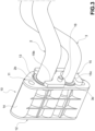
- Fig. 1 shows a heat exchanger of an air conditioning unit, such as an evaporator, collectively denoted by 1.
- the heat exchanger 1 is connected via a pair of pipes 2 and 3 made of metal material (one inlet into the heat exchanger and one outlet out of the heat exchanger) to a circuit for circulating a refrigerant fluid installed in a motor vehicle (not shown).
- Fig. 1 also shows a third pipe and a fourth pipe made of metal material, indicated by 4 and 5, respectively, which are also connected to the connecting block 10 and belong to the refrigerant fluid circuit to which the heat exchanger 1 is connected. Therefore, a first side 11 intended to receive the first pipe and the second pipe 2, 3, and a second side 12 opposite the first side 11 and intended to receive the third pipe and the fourth pipe 4, 5 may be identified in the connecting block 10.
- Fig. 2 to 10 show in greater detail the pipe connecting system formed of the connecting block 10 and of the pipes connected thereto.
- the first pipe and the second pipe 2, 3 each comprise a flared end 2a, 3a.
- Each flared end 2a, 3a comprises a flare 2a', 3a' and, distal to the flare 2a', 3a', an enlarged diameter portion 2a", 3a".
- Each enlarged diameter portion 2a", 3a" has a larger diameter than the remaining part of the relevant pipe, and is connected to that remaining part by the relevant flare 2a', 3a'.
- the terms “distal” and “proximal” mean “farther” and "closer", respectively, in relation to the entity with which the first pipe and the second pipe are associated, which in the example shown consists of the heat exchanger 1.
- first pipe and the second pipe 2, 3 each comprise a flanged portion 2b, 3b extending radially outward and arranged close to the relevant flared end 2a, 3a, in a proximal position with respect thereto.
- the flared portion and flanged portion are obtained on the pipes by conventional pipe machining techniques.
- the connecting block 10 comprises a first block part 13 and a second block part 14 both made of plastics material. These block parts 13, 14 are configured to be fastened to each other around the flared ends 2a, 3a of the first and the second pipe 2, 3. More precisely, when the first block part 13 and the second block part 14 are fastened to each other by closing the connecting block 10 around the first pipe and the second pipe 2, 3, they enclose not only the respective flared portions 2a, 3a, but also a segment of pipe comprised between the flared portions 2a, 3a and the respective flanged portions 2b, 3b. In the example shown, when the connecting block 10 is closed, the first block part 13 and the second block part 14 also enclose the flanged portions 2b, 3b.
- the first block part 13 has a contact surface 13a that, when the connecting block 10 is closed, comes into contact with a corresponding contact surface 14a of the second block part 14.
- Each of these grooves comprises, in the direction that runs from the first side 11 to the second side 12 of the connecting block 10, a stepped segment intended to receive the relevant flanged pipe portion 2b or 3b, a smaller diameter segment intended to receive the relevant pipe portion between the flanged portion and the flared portion, a flared segment intended to receive the relevant flare 2a' or 3a', and an enlarged diameter segment intended to receive the relevant enlarged diameter pipe portion 2a" or 3a".
- x1 and x2 denote the axes of the first pipe 2 and the second pipe 3, respectively.
- a pair of parallel-extending grooves 14b, 14c is obtained between the first side 11 and the second side 12 of the connecting block 10.
- These grooves 14b, 14c have a semicircular cross-section along almost their entire extension, and, when the first block part 13 and the second block part 14 are fixed together by closing the connecting block 10, they are intended to form, together with the grooves 13b, 13c of the first block part 13, the holes or seats in which the first pipe and the second pipe 2, 3 are accommodated, respectively.
- Each of the grooves 14b, 14c of the second block portion 14 comprises, in the direction that runs from the first side 11 to the second side 12 of the connecting block 10, a stepped segment intended to receive the relevant flanged pipe portion 2b or 3b, a smaller diameter segment intended to receive the relevant pipe portion between the flanged portion and the flared portion, a flared segment intended to receive the relevant flare 2a' or 3a', and an enlarged diameter segment intended to receive the relevant enlarged diameter pipe portion 2a" or 3a".
- the second block part 14 comprises a front portion 14d that, when the first block part 13 and the second block part 14 are fixed together, covers a corresponding front surface 13d of the first block part 13.
- the flared segment of the grooves 14b, 14c of the second block part 14 is positioned axially offset from the flared segment of the grooves 13b, 13c of the first block part 13. This makes assembly possible between the block parts with the pipes 2 and 3 already placed in the grooves 13b, 13c of the first block part 13.
- the pipe connecting system further comprises a locking plate 15 made of metal material, which comprises an engaging portion 15a configured to engage simultaneously the flanged portions 2b, 3b of the first pipe and the second pipe 2, 3.
- a pair of lugs 15b, 15c having transverse dimensions slightly larger than the outer diameter of the first pipe 2 and the second pipe 3, respectively, but smaller than the outer diameter of the flanged portions, 2b and 3b, respectively, is obtained in the locking plate 15. This allows the locking plate 15 to be assembled to the pipes 2 and 3 and moved along those pipes until it is brought to engage with the flanged portions 2b and 3b.
- the engaging portion 15a provided by the locking plate 15 is comprised of portions of the surface of that plate facing the connecting block, which are arranged around the edges of the lugs 15b, 15c.
- the locking plate 15 is fixed to the connecting block 10 by at least one screw 16 (in the example, two screws) to hold the first pipe and the second pipe 2, 3 between the connecting block 10 and the locking plate 15.
- screw 16 in the example, two screws
- through-holes are obtained in the connecting block 10 that allow the positioning of the screws 16, while threaded through-holes 15d are obtained in the locking plate, the threads of which through-holes are engaged by the threads of the screws 16.
- the screws 16 act as tie rods that allow the locking plate 15 to be tightened against the flanged portions 2b, 3b of the pipes 2, 3, thus tightening these flanged portions against the connecting block 10.
- no other screws are required for the integrity of the pipe connecting system than those used for fixing the locking plate 15 to the connecting block 10.
- two through-holes 14m, 14n arranged intermediately between the holes 14e and 14f, are obtained in the second block part 14 to accommodate the screws 16.
- the first of these through-holes, 14m spans the entire thickness of the first block part between the first side 11 and the second side 12 of the connecting block.
- the second of these through-holes, 14n spans the thickness of only the front portion 14d of the first block part 14, and is aligned with a corresponding through-hole 13n obtained in the first block part.
- the third pipe 4 and the fourth pipe 5 are provided with at least one support portion 4a, 5a (in the example, one support portion each) laterally extending and carrying a through-hole suitable for receiving a relevant screw 4b, 5b for coupling to the connecting body 10. More specifically, threaded inserts 18 are inserted at the front portion 14d of the second block part 14 for fixing by the screws 4b, 5b of the third pipe 4 and the fourth pipe 5 to the connecting block 10. These threaded inserts 18 may be inserted into the second block part 14 during the molding process of the second block part 14, or they may be set into the second block part 14 at a stage following the molding thereof.
- the connecting block 10 provides a unique surface, namely that provided by the front portion 14d of the second block part 14. This allows precise assembly of the third pipe and the fourth pipe to the connecting block 10, since there are no discontinuities that could cause misalignment between the components.
Landscapes
- Engineering & Computer Science (AREA)
- General Engineering & Computer Science (AREA)
- Mechanical Engineering (AREA)
- Supports For Pipes And Cables (AREA)
Claims (5)
- Rohrverbindungssystem, enthaltend:ein erstes Rohr (2) und ein zweites Rohr (3), wobei jedes ein aufgeweitetes Ende (2a, 3a) aufweist;einen Verbindungsblock (10) mit einer ersten Seite (11), die angedacht ist zum Aufnehmen des ersten Rohrs (2) und des zweiten Rohrs (3), und einer zweiten Seite (12), die gegenüber der ersten Seite (11) ist und angedacht ist zum Aufnehmen eines dritten Rohrs (4) und eines vierten Rohrs (5), wobei der Verbindungsblock (10) einen ersten Blockteil (13) und einen zweiten Blockteil (14) aufweist, die aus Kunststoffmaterial hergestellt sind und ausgebildet sind, dass sie aneinander um die aufgeweiteten Enden (2a, 3a) des ersten Rohrs (2) und des zweiten Rohrs (3) herum befestigt werden;wobei einer aus dem ersten Blockteil und dem zweiten Blockteil eine Vielzahl von hakenförmigen Querhaltebereichen (14g) aufweist, die ausgebildet sind zum Ergreifen entsprechender Querränder (13g) des anderen aus dem ersten Blockteil und dem zweiten Blockteil auf solch eine Weise, dass der erste Blockteil (13) und der zweite Blockteil (14) aneinander befestigt werden;wobei das erste Rohr (2) und das zweite Rohr (3) jeweils einen Flanschbereich (2b, 3b) aufweisen, der nahe dem entsprechenden aufgeweiteten Ende (2a, 3a) angeordnet ist;wobei das Rohrverbindungssystem ferner eine Verriegelungsplatte (15) aufweist, die einen Eingriffsbereich (15a) aufweist, der zum gleichzeitigen Ergreifen der Flanschbereiche (2b, 3b) des ersten Rohrs (2) und des zweiten Rohrs (3) ausgebildet ist,wobei das Verbindungssystem dadurch gekennzeichnet ist, dass die Verriegelungsplatte (15) aus Metallmaterial hergestellt ist und an dem Verbindungsblock (10) durch wenigstens eine Schraube (16) zum Halten des ersten Rohrs (2) und des zweiten Rohrs (3) zwischen dem Verbindungsblock (10) und der Verriegelungsplatte (15) befestigbar ist.
- Verbindungssystem nach Anspruch 1, wobei an der zweiten Seite (12) des Verbindungsblocks (10) einer aus dem ersten Blockteil und dem zweiten Blockteil einen Vorderbereich (14d) aufweist, der eine entsprechende Vorderfläche (13d) des anderen aus dem ersten Blockteil und dem zweiten Blockteil bedeckt.
- Verbindungssystem nach Anspruch 2, wobei wenigstens ein mit Gewinde versehener Einsatz (18) an dem Vorderbereich zum Befestigen des dritten Rohrs und vierten Rohrs an dem Verbindungsblock (10) durch eine entsprechende Schraube (4b, 5b) eingeführt ist.
- Verbindungssystem nach einem der vorhergehenden Ansprüche, ferner enthaltend das dritte Rohr (4) und das vierte Rohr (5), die in entsprechende vergrößerte Durchmesserbereiche (2a", 3a") des ersten Rohrs (2) beziehungsweise des zweiten Rohrs (3) eingeführt sind.
- Verbindungssystem nach Anspruch 3 und 4, wobei das dritte Rohr (4) und das vierte Rohr (5) mit wenigstens einem Stützbereich (4a, 5a) versehen sind, der sich quer erstreckt und ein Durchgangsloch trägt, das angepasst ist zum Aufnehmen einer entsprechenden Schraube (4b, 5b) zum Koppeln mit dem wenigstens einen mit Gewinde versehenen Einsatz (18).
Priority Applications (1)
| Application Number | Priority Date | Filing Date | Title |
|---|---|---|---|
| MA66394A MA66394B1 (fr) | 2022-05-09 | 2023-05-04 | Système de raccordement de tuyaux |
Applications Claiming Priority (1)
| Application Number | Priority Date | Filing Date | Title |
|---|---|---|---|
| IT102022000009467A IT202200009467A1 (it) | 2022-05-09 | 2022-05-09 | Sistema di connessione tubi |
Publications (2)
| Publication Number | Publication Date |
|---|---|
| EP4276339A1 EP4276339A1 (de) | 2023-11-15 |
| EP4276339B1 true EP4276339B1 (de) | 2024-11-27 |
Family
ID=82942450
Family Applications (1)
| Application Number | Title | Priority Date | Filing Date |
|---|---|---|---|
| EP23171612.7A Active EP4276339B1 (de) | 2022-05-09 | 2023-05-04 | Rohrverbindungssystem |
Country Status (5)
| Country | Link |
|---|---|
| EP (1) | EP4276339B1 (de) |
| ES (1) | ES3010634T3 (de) |
| IT (1) | IT202200009467A1 (de) |
| MA (1) | MA66394B1 (de) |
| PL (1) | PL4276339T3 (de) |
Family Cites Families (5)
| Publication number | Priority date | Publication date | Assignee | Title |
|---|---|---|---|---|
| JP3413937B2 (ja) | 1994-03-28 | 2003-06-09 | 株式会社デンソー | 配管接続装置 |
| US6926311B2 (en) * | 2003-09-03 | 2005-08-09 | Apex Medical Corp. | Apparatus for quick connection |
| EP1726862B1 (de) * | 2005-05-27 | 2010-02-24 | NORMA Germany GmbH | Verbindungsanordnung mit koaxialen Endabschnitten zweier zu verbindender Fluidleitungen |
| US7637538B2 (en) * | 2007-04-27 | 2009-12-29 | Behr America, Inc. | Heater core assembly |
| US7731244B2 (en) * | 2007-09-12 | 2010-06-08 | Coolsystems, Inc. | Make-brake connector assembly with opposing latches |
-
2022
- 2022-05-09 IT IT102022000009467A patent/IT202200009467A1/it unknown
-
2023
- 2023-05-04 EP EP23171612.7A patent/EP4276339B1/de active Active
- 2023-05-04 ES ES23171612T patent/ES3010634T3/es active Active
- 2023-05-04 PL PL23171612.7T patent/PL4276339T3/pl unknown
- 2023-05-04 MA MA66394A patent/MA66394B1/fr unknown
Also Published As
| Publication number | Publication date |
|---|---|
| PL4276339T3 (pl) | 2025-04-28 |
| ES3010634T3 (en) | 2025-04-04 |
| EP4276339A1 (de) | 2023-11-15 |
| MA66394B1 (fr) | 2025-02-28 |
| IT202200009467A1 (it) | 2023-11-09 |
Similar Documents
| Publication | Publication Date | Title |
|---|---|---|
| US6070659A (en) | External connection for heat exchanger unit | |
| US3869153A (en) | Double tube mounting assembly | |
| US3869152A (en) | Tube mounting assembly | |
| JP2832813B2 (ja) | インサート付き接続ブロック | |
| US4656689A (en) | Grommet | |
| EP1962008A1 (de) | Ringförmige Klemme | |
| US9194523B2 (en) | V-band clamp with V-insert segments | |
| US6533328B2 (en) | Joint for duplex pipes | |
| GB2446813A (en) | Annular clamp with temporary clip to facilitate assembly | |
| US20050264010A1 (en) | V-band clamp | |
| US5209440A (en) | Hexagonal junction adapter with retaining shoulder | |
| EP4276339B1 (de) | Rohrverbindungssystem | |
| US20030020279A1 (en) | Exhaust system clamp assembly and associated method | |
| SE503085C2 (sv) | Värmeväxlartank med ändstycken, förfarande för framställning av en sådan tank, samt värmeväxlare försedd med en sådan | |
| US10836238B2 (en) | Vehicle components including rib receiving channels for receiving alignment ribs of vehicle panels | |
| KR20170090975A (ko) | 유체 파이프라인 단부들을 고정하기 위한 고정 부재 및 방법 | |
| US5842725A (en) | Clamp as well as pipe connection with a clamp | |
| US20030085023A1 (en) | Bracket for heat exchange ventilation device | |
| US5765881A (en) | Interlocking split flange connector | |
| US4424656A (en) | Assembly clip for ceiling panels | |
| US20020074801A1 (en) | Elbow connection | |
| WO2020037029A1 (en) | Clamp locating system and method | |
| US20070022574A1 (en) | V-channel clamp | |
| EP4545836B1 (de) | Rohrverbindungssystem | |
| US6308410B1 (en) | Method for fixing transverse partitions in the tubular fluid box of a heat exchanger |
Legal Events
| Date | Code | Title | Description |
|---|---|---|---|
| PUAI | Public reference made under article 153(3) epc to a published international application that has entered the european phase |
Free format text: ORIGINAL CODE: 0009012 |
|
| STAA | Information on the status of an ep patent application or granted ep patent |
Free format text: STATUS: THE APPLICATION HAS BEEN PUBLISHED |
|
| AK | Designated contracting states |
Kind code of ref document: A1 Designated state(s): AL AT BE BG CH CY CZ DE DK EE ES FI FR GB GR HR HU IE IS IT LI LT LU LV MC ME MK MT NL NO PL PT RO RS SE SI SK SM TR |
|
| STAA | Information on the status of an ep patent application or granted ep patent |
Free format text: STATUS: REQUEST FOR EXAMINATION WAS MADE |
|
| 17P | Request for examination filed |
Effective date: 20240314 |
|
| RAV | Requested validation state of the european patent: fee paid |
Extension state: MA Effective date: 20240314 |
|
| RBV | Designated contracting states (corrected) |
Designated state(s): AL AT BE BG CH CY CZ DE DK EE ES FI FR GB GR HR HU IE IS IT LI LT LU LV MC ME MK MT NL NO PL PT RO RS SE SI SK SM TR |
|
| GRAP | Despatch of communication of intention to grant a patent |
Free format text: ORIGINAL CODE: EPIDOSNIGR1 |
|
| STAA | Information on the status of an ep patent application or granted ep patent |
Free format text: STATUS: GRANT OF PATENT IS INTENDED |
|
| RIC1 | Information provided on ipc code assigned before grant |
Ipc: F16L 39/00 20060101ALI20240606BHEP Ipc: F16L 21/06 20060101AFI20240606BHEP |
|
| INTG | Intention to grant announced |
Effective date: 20240627 |
|
| GRAS | Grant fee paid |
Free format text: ORIGINAL CODE: EPIDOSNIGR3 |
|
| GRAA | (expected) grant |
Free format text: ORIGINAL CODE: 0009210 |
|
| STAA | Information on the status of an ep patent application or granted ep patent |
Free format text: STATUS: THE PATENT HAS BEEN GRANTED |
|
| AK | Designated contracting states |
Kind code of ref document: B1 Designated state(s): AL AT BE BG CH CY CZ DE DK EE ES FI FR GB GR HR HU IE IS IT LI LT LU LV MC ME MK MT NL NO PL PT RO RS SE SI SK SM TR |
|
| REG | Reference to a national code |
Ref country code: GB Ref legal event code: FG4D |
|
| REG | Reference to a national code |
Ref country code: CH Ref legal event code: EP |
|
| REG | Reference to a national code |
Ref country code: DE Ref legal event code: R096 Ref document number: 602023001153 Country of ref document: DE |
|
| REG | Reference to a national code |
Ref country code: IE Ref legal event code: FG4D |
|
| REG | Reference to a national code |
Ref country code: MA Ref legal event code: VAGR Ref document number: 66394 Country of ref document: MA Kind code of ref document: B1 |
|
| REG | Reference to a national code |
Ref country code: LT Ref legal event code: MG9D |
|
| REG | Reference to a national code |
Ref country code: NL Ref legal event code: MP Effective date: 20241127 |
|
| REG | Reference to a national code |
Ref country code: ES Ref legal event code: FG2A Ref document number: 3010634 Country of ref document: ES Kind code of ref document: T3 Effective date: 20250404 |
|
| PG25 | Lapsed in a contracting state [announced via postgrant information from national office to epo] |
Ref country code: IS Free format text: LAPSE BECAUSE OF FAILURE TO SUBMIT A TRANSLATION OF THE DESCRIPTION OR TO PAY THE FEE WITHIN THE PRESCRIBED TIME-LIMIT Effective date: 20250327 Ref country code: PT Free format text: LAPSE BECAUSE OF FAILURE TO SUBMIT A TRANSLATION OF THE DESCRIPTION OR TO PAY THE FEE WITHIN THE PRESCRIBED TIME-LIMIT Effective date: 20250327 Ref country code: HR Free format text: LAPSE BECAUSE OF FAILURE TO SUBMIT A TRANSLATION OF THE DESCRIPTION OR TO PAY THE FEE WITHIN THE PRESCRIBED TIME-LIMIT Effective date: 20241127 |
|
| PG25 | Lapsed in a contracting state [announced via postgrant information from national office to epo] |
Ref country code: FI Free format text: LAPSE BECAUSE OF FAILURE TO SUBMIT A TRANSLATION OF THE DESCRIPTION OR TO PAY THE FEE WITHIN THE PRESCRIBED TIME-LIMIT Effective date: 20241127 Ref country code: NL Free format text: LAPSE BECAUSE OF FAILURE TO SUBMIT A TRANSLATION OF THE DESCRIPTION OR TO PAY THE FEE WITHIN THE PRESCRIBED TIME-LIMIT Effective date: 20241127 |
|
| REG | Reference to a national code |
Ref country code: AT Ref legal event code: MK05 Ref document number: 1746013 Country of ref document: AT Kind code of ref document: T Effective date: 20241127 |
|
| PG25 | Lapsed in a contracting state [announced via postgrant information from national office to epo] |
Ref country code: BG Free format text: LAPSE BECAUSE OF FAILURE TO SUBMIT A TRANSLATION OF THE DESCRIPTION OR TO PAY THE FEE WITHIN THE PRESCRIBED TIME-LIMIT Effective date: 20241127 |
|
| PG25 | Lapsed in a contracting state [announced via postgrant information from national office to epo] |
Ref country code: NO Free format text: LAPSE BECAUSE OF FAILURE TO SUBMIT A TRANSLATION OF THE DESCRIPTION OR TO PAY THE FEE WITHIN THE PRESCRIBED TIME-LIMIT Effective date: 20250227 |
|
| PG25 | Lapsed in a contracting state [announced via postgrant information from national office to epo] |
Ref country code: LV Free format text: LAPSE BECAUSE OF FAILURE TO SUBMIT A TRANSLATION OF THE DESCRIPTION OR TO PAY THE FEE WITHIN THE PRESCRIBED TIME-LIMIT Effective date: 20241127 Ref country code: GR Free format text: LAPSE BECAUSE OF FAILURE TO SUBMIT A TRANSLATION OF THE DESCRIPTION OR TO PAY THE FEE WITHIN THE PRESCRIBED TIME-LIMIT Effective date: 20250228 Ref country code: AT Free format text: LAPSE BECAUSE OF FAILURE TO SUBMIT A TRANSLATION OF THE DESCRIPTION OR TO PAY THE FEE WITHIN THE PRESCRIBED TIME-LIMIT Effective date: 20241127 |
|
| PG25 | Lapsed in a contracting state [announced via postgrant information from national office to epo] |
Ref country code: RS Free format text: LAPSE BECAUSE OF FAILURE TO SUBMIT A TRANSLATION OF THE DESCRIPTION OR TO PAY THE FEE WITHIN THE PRESCRIBED TIME-LIMIT Effective date: 20250227 |
|
| PG25 | Lapsed in a contracting state [announced via postgrant information from national office to epo] |
Ref country code: SM Free format text: LAPSE BECAUSE OF FAILURE TO SUBMIT A TRANSLATION OF THE DESCRIPTION OR TO PAY THE FEE WITHIN THE PRESCRIBED TIME-LIMIT Effective date: 20241127 |
|
| PGFP | Annual fee paid to national office [announced via postgrant information from national office to epo] |
Ref country code: DE Payment date: 20250523 Year of fee payment: 3 Ref country code: PL Payment date: 20250505 Year of fee payment: 3 |
|
| PG25 | Lapsed in a contracting state [announced via postgrant information from national office to epo] |
Ref country code: DK Free format text: LAPSE BECAUSE OF FAILURE TO SUBMIT A TRANSLATION OF THE DESCRIPTION OR TO PAY THE FEE WITHIN THE PRESCRIBED TIME-LIMIT Effective date: 20241127 |
|
| PGFP | Annual fee paid to national office [announced via postgrant information from national office to epo] |
Ref country code: ES Payment date: 20250602 Year of fee payment: 3 |
|
| PG25 | Lapsed in a contracting state [announced via postgrant information from national office to epo] |
Ref country code: EE Free format text: LAPSE BECAUSE OF FAILURE TO SUBMIT A TRANSLATION OF THE DESCRIPTION OR TO PAY THE FEE WITHIN THE PRESCRIBED TIME-LIMIT Effective date: 20241127 |
|
| PGFP | Annual fee paid to national office [announced via postgrant information from national office to epo] |
Ref country code: FR Payment date: 20250430 Year of fee payment: 3 |
|
| PGFP | Annual fee paid to national office [announced via postgrant information from national office to epo] |
Ref country code: RO Payment date: 20250422 Year of fee payment: 3 |
|
| PG25 | Lapsed in a contracting state [announced via postgrant information from national office to epo] |
Ref country code: SK Free format text: LAPSE BECAUSE OF FAILURE TO SUBMIT A TRANSLATION OF THE DESCRIPTION OR TO PAY THE FEE WITHIN THE PRESCRIBED TIME-LIMIT Effective date: 20241127 |
|
| PGFP | Annual fee paid to national office [announced via postgrant information from national office to epo] |
Ref country code: TR Payment date: 20250426 Year of fee payment: 3 |
|
| PG25 | Lapsed in a contracting state [announced via postgrant information from national office to epo] |
Ref country code: CZ Free format text: LAPSE BECAUSE OF FAILURE TO SUBMIT A TRANSLATION OF THE DESCRIPTION OR TO PAY THE FEE WITHIN THE PRESCRIBED TIME-LIMIT Effective date: 20241127 |
|
| PG25 | Lapsed in a contracting state [announced via postgrant information from national office to epo] |
Ref country code: IT Free format text: LAPSE BECAUSE OF FAILURE TO SUBMIT A TRANSLATION OF THE DESCRIPTION OR TO PAY THE FEE WITHIN THE PRESCRIBED TIME-LIMIT Effective date: 20241127 |
|
| REG | Reference to a national code |
Ref country code: DE Ref legal event code: R097 Ref document number: 602023001153 Country of ref document: DE |
|
| PG25 | Lapsed in a contracting state [announced via postgrant information from national office to epo] |
Ref country code: SE Free format text: LAPSE BECAUSE OF FAILURE TO SUBMIT A TRANSLATION OF THE DESCRIPTION OR TO PAY THE FEE WITHIN THE PRESCRIBED TIME-LIMIT Effective date: 20241127 |
|
| PLBE | No opposition filed within time limit |
Free format text: ORIGINAL CODE: 0009261 |
|
| STAA | Information on the status of an ep patent application or granted ep patent |
Free format text: STATUS: NO OPPOSITION FILED WITHIN TIME LIMIT |
|
| 26N | No opposition filed |
Effective date: 20250828 |
|
| VSFP | Annual fee paid to validation state [announced via postgrant information from national office to epo] |
Ref country code: MA Payment date: 20250507 Year of fee payment: 3 |
|
| PG25 | Lapsed in a contracting state [announced via postgrant information from national office to epo] |
Ref country code: LU Free format text: LAPSE BECAUSE OF NON-PAYMENT OF DUE FEES Effective date: 20250504 |
|
| PG25 | Lapsed in a contracting state [announced via postgrant information from national office to epo] |
Ref country code: MC Free format text: LAPSE BECAUSE OF FAILURE TO SUBMIT A TRANSLATION OF THE DESCRIPTION OR TO PAY THE FEE WITHIN THE PRESCRIBED TIME-LIMIT Effective date: 20241127 |