EP4276284A1 - Système et procédé d'antigivrage d'aubes directrices d'entrée - Google Patents
Système et procédé d'antigivrage d'aubes directrices d'entrée Download PDFInfo
- Publication number
- EP4276284A1 EP4276284A1 EP23172659.7A EP23172659A EP4276284A1 EP 4276284 A1 EP4276284 A1 EP 4276284A1 EP 23172659 A EP23172659 A EP 23172659A EP 4276284 A1 EP4276284 A1 EP 4276284A1
- Authority
- EP
- European Patent Office
- Prior art keywords
- vane
- inlet guide
- radially
- air
- guide vane
- Prior art date
- Legal status (The legal status is an assumption and is not a legal conclusion. Google has not performed a legal analysis and makes no representation as to the accuracy of the status listed.)
- Pending
Links
- 238000000034 method Methods 0.000 title claims description 11
- 238000004891 communication Methods 0.000 claims abstract description 19
- 239000012530 fluid Substances 0.000 claims abstract description 18
- 230000037361 pathway Effects 0.000 claims abstract description 8
- 238000007789 sealing Methods 0.000 claims description 4
- 230000000740 bleeding effect Effects 0.000 claims description 2
- 239000003570 air Substances 0.000 description 95
- 239000007789 gas Substances 0.000 description 7
- 238000011144 upstream manufacturing Methods 0.000 description 5
- 239000012080 ambient air Substances 0.000 description 4
- 238000010438 heat treatment Methods 0.000 description 4
- 238000005516 engineering process Methods 0.000 description 3
- 238000000429 assembly Methods 0.000 description 2
- 230000000712 assembly Effects 0.000 description 2
- 230000015572 biosynthetic process Effects 0.000 description 2
- 239000000567 combustion gas Substances 0.000 description 2
- 238000012986 modification Methods 0.000 description 2
- 230000004048 modification Effects 0.000 description 2
- 239000007787 solid Substances 0.000 description 2
- 238000010586 diagram Methods 0.000 description 1
- 239000000446 fuel Substances 0.000 description 1
- 238000005259 measurement Methods 0.000 description 1
- 238000012545 processing Methods 0.000 description 1
- 238000012552 review Methods 0.000 description 1
- 230000000153 supplemental effect Effects 0.000 description 1
Images


Classifications
-
- F—MECHANICAL ENGINEERING; LIGHTING; HEATING; WEAPONS; BLASTING
- F02—COMBUSTION ENGINES; HOT-GAS OR COMBUSTION-PRODUCT ENGINE PLANTS
- F02C—GAS-TURBINE PLANTS; AIR INTAKES FOR JET-PROPULSION PLANTS; CONTROLLING FUEL SUPPLY IN AIR-BREATHING JET-PROPULSION PLANTS
- F02C7/00—Features, components parts, details or accessories, not provided for in, or of interest apart form groups F02C1/00 - F02C6/00; Air intakes for jet-propulsion plants
- F02C7/04—Air intakes for gas-turbine plants or jet-propulsion plants
- F02C7/047—Heating to prevent icing
-
- F—MECHANICAL ENGINEERING; LIGHTING; HEATING; WEAPONS; BLASTING
- F01—MACHINES OR ENGINES IN GENERAL; ENGINE PLANTS IN GENERAL; STEAM ENGINES
- F01D—NON-POSITIVE DISPLACEMENT MACHINES OR ENGINES, e.g. STEAM TURBINES
- F01D17/00—Regulating or controlling by varying flow
- F01D17/10—Final actuators
- F01D17/12—Final actuators arranged in stator parts
- F01D17/14—Final actuators arranged in stator parts varying effective cross-sectional area of nozzles or guide conduits
- F01D17/16—Final actuators arranged in stator parts varying effective cross-sectional area of nozzles or guide conduits by means of nozzle vanes
- F01D17/162—Final actuators arranged in stator parts varying effective cross-sectional area of nozzles or guide conduits by means of nozzle vanes for axial flow, i.e. the vanes turning around axes which are essentially perpendicular to the rotor centre line
-
- F—MECHANICAL ENGINEERING; LIGHTING; HEATING; WEAPONS; BLASTING
- F01—MACHINES OR ENGINES IN GENERAL; ENGINE PLANTS IN GENERAL; STEAM ENGINES
- F01D—NON-POSITIVE DISPLACEMENT MACHINES OR ENGINES, e.g. STEAM TURBINES
- F01D25/00—Component parts, details, or accessories, not provided for in, or of interest apart from, other groups
- F01D25/02—De-icing means for engines having icing phenomena
-
- F—MECHANICAL ENGINEERING; LIGHTING; HEATING; WEAPONS; BLASTING
- F01—MACHINES OR ENGINES IN GENERAL; ENGINE PLANTS IN GENERAL; STEAM ENGINES
- F01D—NON-POSITIVE DISPLACEMENT MACHINES OR ENGINES, e.g. STEAM TURBINES
- F01D9/00—Stators
- F01D9/06—Fluid supply conduits to nozzles or the like
- F01D9/065—Fluid supply or removal conduits traversing the working fluid flow, e.g. for lubrication-, cooling-, or sealing fluids
-
- F—MECHANICAL ENGINEERING; LIGHTING; HEATING; WEAPONS; BLASTING
- F05—INDEXING SCHEMES RELATING TO ENGINES OR PUMPS IN VARIOUS SUBCLASSES OF CLASSES F01-F04
- F05D—INDEXING SCHEME FOR ASPECTS RELATING TO NON-POSITIVE-DISPLACEMENT MACHINES OR ENGINES, GAS-TURBINES OR JET-PROPULSION PLANTS
- F05D2220/00—Application
- F05D2220/30—Application in turbines
- F05D2220/32—Application in turbines in gas turbines
- F05D2220/321—Application in turbines in gas turbines for a special turbine stage
- F05D2220/3216—Application in turbines in gas turbines for a special turbine stage for a special compressor stage
- F05D2220/3217—Application in turbines in gas turbines for a special turbine stage for a special compressor stage for the first stage of a compressor or a low pressure compressor
-
- Y—GENERAL TAGGING OF NEW TECHNOLOGICAL DEVELOPMENTS; GENERAL TAGGING OF CROSS-SECTIONAL TECHNOLOGIES SPANNING OVER SEVERAL SECTIONS OF THE IPC; TECHNICAL SUBJECTS COVERED BY FORMER USPC CROSS-REFERENCE ART COLLECTIONS [XRACs] AND DIGESTS
- Y02—TECHNOLOGIES OR APPLICATIONS FOR MITIGATION OR ADAPTATION AGAINST CLIMATE CHANGE
- Y02T—CLIMATE CHANGE MITIGATION TECHNOLOGIES RELATED TO TRANSPORTATION
- Y02T50/00—Aeronautics or air transport
- Y02T50/60—Efficient propulsion technologies, e.g. for aircraft
Definitions
- the present invention relates generally to aircraft engines and, more particularly, to anti-icing of vanes in aircraft engines.
- IGVs Inlet Guide Vanes located upstream of a first compressor rotor within the air inlet of the engine.
- IGVs may be either fixed or may be variable IGVs that can be pivoted about respective airfoil axes as required to direct airflow into the engine.
- anti-icing of the IGVs is required during flight to prevent ice formation and/or buildup on the surfaces of the vanes.
- This anti-icing of IGVs is typically accomplished by ducting warm air, which may be bled from the compressor further downstream, outside of the engine casing back to the radially outer ends of the IGVs. This warm anti-icing air, once it has been used to heat the IGVs, gets exhausted back into the main gas path of the engine and thus gets ingested back into the engine.
- an inlet guide vane assembly for an aircraft engine, comprising: an array of inlet guide vanes extending between a radially inner shroud and a radially outer shroud; and an inlet guide vane of the array of inlet guide vanes having a radially inner end at the radially inner shroud, a radially outer end at the radially outer shroud, and an airfoil extending between the radially inner end and the radially outer end, the inlet guide vane having an internal passage extending radially through the airfoil from a vane air inlet at the radially inner end to a vane air outlet at the radially outer end, the vane air inlet in fluid communication with an inner plenum disposed radially inwardly of the inlet guide vane, the inner plenum in fluid communication with an anti-icing air source, the vane air outlet in fluid communication with an outer plenum disposed radially outwardly of the
- the inlet guide vane assembly as defined above and described herein may further include one or more of the following features, in whole or in part, and in any combination.
- the internal passage extending radially through the airfoil is defined by a hollow inner cavity of the inlet guide vane.
- the airfoil is a solid-body airfoil
- the internal passage extending radially through the airfoil is defined by one or more passages formed through the solid-body airfoil.
- the exhaust port includes a valve for selectively sealing the outer plenum.
- inlet guide vane is a variable inlet guide vane.
- each vane of the array of inlet guide vanes comprises the inlet guide vane.
- an aircraft engine comprising: a compressor section having a compressor inlet, a radially inner shroud, a radially outer shroud, and a compressor rotor; an anti-icing air source; an inlet guide vane radially disposed between the radially inner shroud and the radially outer shroud and located upstream of the compressor rotor in the compressor section, the inlet guide vane having a radially inner end at the radially inner shroud, a radially outer end at the radially outer shroud, and an airfoil extending between the radially inner end and the radially outer end, the inlet guide vane having an internal passage extending radially through the airfoil from a vane air inlet at the radially inner end to a vane air outlet at the radially outer end; an inner plenum disposed radially inwardly of the inlet guide vane, the inner plenum in fluid communication with
- the aircraft engine as defined above and described herein may further include one or more of the following features, in whole or in part, and in any combination.
- the internal passage extends radially through the airfoil is defined by a hollow inner cavity of the inlet guide vane.
- the airfoil is a solid-body airfoil
- the internal passage extending radially through the airfoil is defined by one or more passages formed through the solid-body airfoil.
- the exhaust port includes a valve for selectively sealing the outer plenum.
- the outer plenum is in fluid communication with a bypass duct of the aircraft engine via the exhaust port.
- the inlet guide vane is a variable inlet guide vane.
- the anti-icing air source is bleed air from a low pressure compressor of the compressor section.
- the inner plenum is in fluid communication with an additional anti-icing air source.
- the additional anti-icing air source is bleed air from a high pressure compressor of the compressor section.
- a method for anti-icing an inlet guide vane in an aircraft engine comprising: directing hot anti-icing air from an inner plenum disposed radially inwardly of the inlet guide vane through a vane air inlet at a radially inner end of the inlet guide vane; directing the hot anti-icing air in a radially-outward direction through an internal passage within the inlet guide vane, from the vane air inlet at the radially inner end of the inlet guide vane towards a vane air outlet at a radially outer end of the inlet guide vane; directing the hot anti-icing air through the vane air outlet at the radially outer end of the inlet guide vane into an outer plenum disposed radially outwardly of the inlet guide vane; and exhausting the hot anti-icing air from the outer plenum via an exhaust port.
- the method as defined above and described herein may further include one or more of the following features, in whole or in part, and in any combination.
- the method includes bleeding the hot anti-icing air from a compressor of the aircraft engine and directing the hot anti-icing air into the inner plenum.
- directing the hot anti-icing air in the radially-outward direction through the internal passage within the inlet guide vane includes directing the hot anti-icing air through a hollow inner cavity of the inlet guide vane.
- exhausting the hot anti-icing air from the outer plenum includes exhausting the hot anti-icing air from the outer plenum to a bypass duct of the aircraft engine via the exhaust port.
- exhausting the hot anti-icing air from the outer plenum includes exhausting the hot anti-icing air overboard via the exhaust port.
- FIG. 1 illustrates an aircraft engine 10 of a type preferably provided for use in subsonic flight.
- the aircraft engine 10 in this case is a gas turbine engine, generally comprising in serial flow communication, along a centerline CL, a fan 12 through which ambient air is propelled, a compressor section 14 for pressurizing the air, a combustor 16 in which the compressed air is mixed with fuel and ignited for generating an annular stream of hot combustion gases, and a turbine section 18 including at least one turbine for extracting energy from the combustion gases.
- Engine 10 may comprise vane assembly(ies) 20. Vane assembly(ies) 20 may be disposed in the multistage compressor 14 in a core section of engine 10.
- Bypass duct 22 may define an annular passage (e.g.
- gas turbine engine 10 is illustrated as a turbofan engine, it is understood that the devices, assemblies and methods described herein could also be used in conjunction with other types of gas turbine engines such as, for example, turboshaft and/or turboprop engines, as well as hybrid aircraft engines.
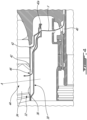
- FIG. 2 shows an axial cross-section view of engine 10 specifically showing an inlet 24 to compressor section 14, with vane assembly(ies) 20 disposed adjacent compressor rotor blade 26.
- Vane assembly(ies) 20 are illustratively disposed upstream of a first compressor rotor 26 and may thus be referred to as inlet guide vane (IGV) assemblies.
- IGV inlet guide vane
- additional vane assembly(ies) 20' may be disposed downstream of a first compressor rotor 26 as well.
- Compressor rotor 26 includes a plurality of compressor blades and is configured to rotate and compress air as it flows towards combustor 16.
- Inlet guide vane assembly(ies) 20 may be used to direct a stream of air towards the compressor rotor 26 to be compressed in compressor section 14.
- Inlet guide vane assembly(ies) 20 may be disposed upstream of a relatively low pressure (e.g. boost) section of compressor 14.
- engine 10 is a two spool engine and compressor blade(s) 26 form part of a low pressure compressor of the compressor section 14.
- the proximity of vane assembly(ies) 20 to the inlet 24, and thus their exposure to the ambient air, may contribute to the need for anti-icing of the vane assembly(ies) 20.
- Other configurations may be contemplated as well.
- vane assembly(ies) 20 may comprise a radially outer shroud 28, a radially inner shroud 30 and a vane 32.
- the outer shroud 28 may, for example, include a radially outer casing of compressor section 14.
- the outer shroud 28 may comprise multiple pieces.
- the inner shroud 30 may, for example, include a radially inner casing of compressor section 14. Similar to the outer shroud 28, the inner shroud 30 may also be provided in multiple pieces.
- Vane(s) 32 may include airfoil(s) or airfoil-shaped body(ies) 34, radially outer end portion(s) 38 and radially inner end portion(s) 36, with the airfoil-shaped body(ies) 34 extending between the radially inner end portion(s) 36 and the radially outer end portion(s) 38.
- Vane(s) 32 are disposed between the radially outer shroud 28 and radially inner shroud 30 and may be used to direct a stream of air towards the compressor blade(s) 26. Vane(s) 32 may be stationary or fixed.
- vane(s) 32 may be variable or pivotable about an axis A extending along a length of the vane 32 between the outer shroud 28 and the inner shroud 30.
- vane(s) 32 may be referred to as a variable inlet guide vane(s) (VIGV's).
- the engine 10 includes a system for heating the vane assembly(ies) 20, also referred to as a vane anti-icing system.
- a flow of hot anti-icing air F from the engine 10, for instance bleed air from compressor section 14, is directed through the vane(s) 32 in a radially-outward direction to prevent ice build-up on the vane(s) 32.
- the temperature of the hot anti-icing air F may vary, but is warm enough to prevent ice formation on the vane assembly(ies) 20 and/or defrost vane assembly(ies) if any ice has already built up thereon.
- a vane heating (or anti-icing) pathway extends from a heated air source 40, for instance the engine core, into a radially inner plenum 42 disposed radially inwardly of the vane(s) 32.
- the pathway then leads an internal passage 44 enclosed by the airfoil-shaped body(ies) 34 of the vanes) 32 and extending radially through the vane(s) 32, entering and exiting the vane(s) via a vane air inlet 46 at the inner end portion(s) 36 and a vane air outlet 48 at the outer end portion(s) 38.
- the internal passage 44 extends from the radially inner end portion 36 to the radially outer end portion 38 in what may or may not be a perfectly radial direction.
- the internal passage 44 may be aligned in a straight, radial direction through the vane 32.
- the internal passage may define a sinusoidal or other curved path through the vane 32.
- the internal passage 44 is a single passageway bored or otherwise formed through a solid airfoil-shaped body(ies) 34 of the vane(s) 32.
- the airfoil-shaped body(ies) 34 of the vane(s) 32 may be hollow, and the internal passage 44 may occupy an entire hollow inner cavity of the vane(s) 32.
- Other internal passages 44 through the vane(s) 32 may be contemplated.
- two or more internal passages may be bored or otherwise formed through a solid airfoil-shaped body(ies) 34 of the vane(s) 32.
- the heating pathway then leads to a radially outer plenum 50 disposed radially outwardly of the vane(s) 32, the radially outer plenum 50 having an exhaust port 52.
- the vane anti-icing system may thus include a vane (or vanes) 32 radially disposed between radially inner shroud 30 and radially outer shroud 28.
- the vane 32 has a radially inner end 36 at the radially inner shroud 30, a radially outer end 38 at the radially outer shroud 28, and an airfoil 34 extending between the radially inner end 36 and the radially outer end 38.
- the vane 32 has an internal passage 44 extending through the airfoil 34 from a vane air inlet 46 at the radially inner end 36 to a vane air outlet 48 at the radially outer end 38.
- the vane air inlet 46 is in fluid communication with an inner plenum 42 disposed radially inwardly of the vane 32.
- the inner plenum is further in fluid communication with an anti-icing air source 40.
- the vane air outlet 48 is in fluid communication with an outer plenum 50 disposed radially outwardly of the vane 32 and has an exhaust port 52.
- a vane anti-icing pathway is defined through the inner plenum 42, the internal passage 44 and the outer plenum 50 in a radially-outward direction.
- the inner plenum 42 may be formed in the inner shroud 30 adjacent the inner end portion(s) 36 of vane(s) 32.
- the inner plenum 42 is annular and extends about a circumference of the inner shroud 30.
- the inner plenum 42 may provide hot anti-icing air F to each of the vane(s) 32.
- multiple inner plenums 42 may be positioned circumferentially-adjacent one another along a circumference of the inner plenum 42. For instance, each of the multiple inner plenums 42 may provide hot anti-icing air F to adjacently-disposed respective one or more vane(s) 32.
- the inner plenum(s) 42 may include an inner plenum inlet 42a through which hot anti-icing air F may enter from, for instance, the engine core. The hot anti-icing air F then may pass through the inner plenum(s) 42 and enter the vane(s) 32 through the vane air inlet(s) 46 at the inner end portion(S) 36 of vane(s) 32.
- inner plenum inlet 42a may include a valve (not shown) for controlling the flow of hot anti-icing air F into the inner plenum(s) 42.
- the outer plenum 50 may be formed in the outer shroud 28 adjacent the outer end portion(s) 38 of the vane(s) 32.
- the outer plenum 50 is annular and extends about a circumference of the outer shroud 28.
- the outer plenum may receive hot anti-icing air F from each of the vane(s) 32.
- multiple outer plenums 50 may positioned circumferentially-adjacent one another along a circumference of the outer shroud 28.
- each of the multiple outer plenums 50 may receive hot anti-icing air F from adjacently-disposed respective one or more vane(s) 32.
- the outer plenum(s) 50 may receive hot anti-icing air F from the vane air outlet(s) 48 of each vane 32.
- the hot anti-icing air F may then pass through the outer plenum(s) 50 and exit via exhaust port 52.
- Exhaust port 52 may include a valve (not shown) for selectively opening and closing the exhaust port 52, thereby metering the quantity of hot anti-icing air F exhausted from the outer plenum 50.
- This valve may be a line-replaceable unit without any piping, which may contribute to weight savings and minimize the overall complexity of the vane anti-icing system.
- Other sealing means for exhaust port 52 may be contemplated.
- exhaust port 52 may be selectively sealed to control the flow of hot anti-icing air F through the vane(s) 32, as the inability of hot anti-icing air F to exit the outer plenum 50 may prevent upstream hot anti-icing air F (relative to the vane heating pathway) from entering the vane(s) 32 from the inner plenum(s) 42.
- hot anti-icing air F may be exhausted from the outer plenum(s) 50 overboard via exhaust port 52.
- hot anti-icing air F may be exhausted from the outer plenum(s) 50 into the bypass duct 22 via exhaust port 52.
- additional or supplemental hot anti-icing air may be provided to anti-ice the vane(s) 32, if needed.
- additional hot anti-icing air may be provided to anti-ice the vane(s) 32, if needed.
- ducting or piping 54 may direct the additional hot air from an additional, supplementary or secondary air source (not shown).
- secondary air source may be, for instance a downstream location of the engine 10 (with reference to main airflow path), for instance at an inlet or an outlet of a high pressure compressor of the compressor section 14, or from the combustor 16.
- Other secondary air sources may be contemplated as well.
- the main or primary heated air source 40 is bleed air from a low pressure compressor of the compressor section 14, while the secondary or additional air source is bleed air from the high pressure compressor of the compressor section 14.
- heated pressurized air can be bled from one or more sources such as the compressor section 14 and combustor 16 and directed through the engine 10 to the inner plenum 42, for instance via ducts within a hollow central engine shaft 56.
- a control system 100 for controlling the anti-icing of the vane(s) 32.
- the system 100 may be used to control the quantity of hot anti-icing air F (and additional hot air, if applicable) directed to the vane(s) 32.
- the system 100 includes a control unit 102, which is coupled to the engine 10 as well as to one or more engine sensors 104.
- the control unit 102 may include a digital computer or Engine Control Unit (ECU) (not shown) using a Central Processing Unit (CPU) (not shown).
- ECU Engine Control Unit
- CPU Central Processing Unit
- Engine sensor(s) 104 may include one or more temperature sensors for measuring air temperature at various positions within the engine 10. For instance, a temperature sensor may be disposed at the inlet 24 to compressor section 14. Other locations for temperature sensors, for instance adjacent the vane(s) 32, may be contemplated as well. Engine sensor(s) 104 may additionally include other sensors such as pressure sensors. As such, engine sensor(s) 104 may be configured for taking one or more measurements indicative of an operating condition adjacent the vane(s) 32 and reporting this condition to the control unit 102. The control unit 102 may then determine whether the reported operating condition, for instance the temperature at or near the vane(s) 32, is conducive to ice build-up on the vane(s) 32.
- control unit 102 may transmit instructions to the engine 10 to anti-ice the vane(s) 32.
- the transmitted instructions may include opening the valves at the inner plenum inlet 42a at the inner plenum(s) 42 and/or the exhaust port 52 at the outer plenum(s) 50 to allow the hot anti-icing air F to flow through the vane(s) 32.
- the degree to which these valves are open may be modulated based on the determined level of anti-icing required.
- control unit 102 may transmit instructions to the engine 10 to direct additional hot air to the vane(s) 32 for additional anti-icing, for instance due to extremely low ambient air temperatures.
- the delivery of hot anti-icing air to the vane(s) 32 may thus be controlled based on a variety of factors and may vary as said factors change, for instance throughout a given flight. Other considerations and instructions may be contemplated.
- the present disclosure teaches a method for anti-icing a vane 32 in an aircraft engine 10.
- Hot anti-icing air is directed from an inner plenum 42 disposed radially inwardly of the vane 32 through a vane air inlet 46 at a radially inner end 36 of the vane 32.
- the hot anti-icing air is directed in a radially-outward direction through a internal passage 44 in the vane 32 towards a vane air outlet 48 at a radially outer end 38 of the vane 32.
- the hot anti-icing air from the internal passage 44 in the vane 32 is directed through the vane air outlet 48 into an outer plenum 50 disposed radially outwardly of the vane 32.
- the hot anti-icing air is exhausted from the outer plenum 50 via an exhaust port 52.
Landscapes
- Engineering & Computer Science (AREA)
- Chemical & Material Sciences (AREA)
- Combustion & Propulsion (AREA)
- Mechanical Engineering (AREA)
- General Engineering & Computer Science (AREA)
- Physics & Mathematics (AREA)
- Fluid Mechanics (AREA)
- Structures Of Non-Positive Displacement Pumps (AREA)
Applications Claiming Priority (1)
| Application Number | Priority Date | Filing Date | Title |
|---|---|---|---|
| US17/662,673 US11698024B1 (en) | 2022-05-10 | 2022-05-10 | System and method of anti-icing inlet guide vanes |
Publications (1)
| Publication Number | Publication Date |
|---|---|
| EP4276284A1 true EP4276284A1 (fr) | 2023-11-15 |
Family
ID=86331276
Family Applications (1)
| Application Number | Title | Priority Date | Filing Date |
|---|---|---|---|
| EP23172659.7A Pending EP4276284A1 (fr) | 2022-05-10 | 2023-05-10 | Système et procédé d'antigivrage d'aubes directrices d'entrée |
Country Status (3)
| Country | Link |
|---|---|
| US (1) | US11698024B1 (fr) |
| EP (1) | EP4276284A1 (fr) |
| CA (1) | CA3197739A1 (fr) |
Families Citing this family (1)
| Publication number | Priority date | Publication date | Assignee | Title |
|---|---|---|---|---|
| US12092027B1 (en) * | 2023-07-06 | 2024-09-17 | Rolls-Royce North American Technologies Inc. | Manifold assembly and anti-ice system for gas turbine engine |
Citations (5)
| Publication number | Priority date | Publication date | Assignee | Title |
|---|---|---|---|---|
| US5029440A (en) * | 1990-01-26 | 1991-07-09 | The United States Of America As Represented By The Secretary Of The Air Force | Acoustical anti-icing system |
| EP0357173B1 (fr) * | 1988-08-24 | 1992-08-12 | General Motors Corporation | Système antigivrage pour séparateur de particules |
| FR2734320A1 (fr) * | 1995-05-15 | 1996-11-22 | Aerospatiale | Dispositif pour prelever et refroidir de l'air chaud au niveau d'un moteur d'aeronef |
| EP0743434B1 (fr) * | 1995-05-15 | 2000-03-01 | Aerospatiale Matra | Dispositif pour prélever et refroidir de l'air chaud au niveau d'un moteur d'aéronef |
| US20050081530A1 (en) * | 2003-10-15 | 2005-04-21 | Bagnall Adam M. | Arrangement for bleeding the boundary layer from an aircraft engine |
Family Cites Families (8)
| Publication number | Priority date | Publication date | Assignee | Title |
|---|---|---|---|---|
| US3123283A (en) | 1962-12-07 | 1964-03-03 | Anti-icing valve means | |
| GB973401A (en) * | 1963-08-30 | 1964-10-28 | Rolls Royce | Gas turbine engine |
| FR2746141B1 (fr) | 1996-03-14 | 1998-04-17 | Dispositif de commande pour pivot integre dans un collecteur | |
| FR2857699B1 (fr) | 2003-07-17 | 2007-06-29 | Snecma Moteurs | Dispositif de degivrage pour aube de roue directrice d'entree de turbomachine, aube dotee d'un tel dispositif de degivrage, et moteur d'aeronef equipe de telles aubes |
| US9127566B2 (en) * | 2012-04-02 | 2015-09-08 | United Technologies Corporation | Turbomachine thermal management |
| FR3051219B1 (fr) * | 2016-05-12 | 2019-06-07 | Safran Aircraft Engines | Aube de turbomachine, telle par exemple qu'un turboreacteur ou un turbopropulseur d'avion |
| US10260371B2 (en) * | 2016-05-20 | 2019-04-16 | Pratt & Whitney Canada Corp. | Method and assembly for providing an anti-icing airflow |
| US10443497B2 (en) | 2016-08-10 | 2019-10-15 | Rolls-Royce Corporation | Ice protection system for gas turbine engines |
-
2022
- 2022-05-10 US US17/662,673 patent/US11698024B1/en active Active
-
2023
- 2023-04-21 CA CA3197739A patent/CA3197739A1/fr active Pending
- 2023-05-10 EP EP23172659.7A patent/EP4276284A1/fr active Pending
Patent Citations (5)
| Publication number | Priority date | Publication date | Assignee | Title |
|---|---|---|---|---|
| EP0357173B1 (fr) * | 1988-08-24 | 1992-08-12 | General Motors Corporation | Système antigivrage pour séparateur de particules |
| US5029440A (en) * | 1990-01-26 | 1991-07-09 | The United States Of America As Represented By The Secretary Of The Air Force | Acoustical anti-icing system |
| FR2734320A1 (fr) * | 1995-05-15 | 1996-11-22 | Aerospatiale | Dispositif pour prelever et refroidir de l'air chaud au niveau d'un moteur d'aeronef |
| EP0743434B1 (fr) * | 1995-05-15 | 2000-03-01 | Aerospatiale Matra | Dispositif pour prélever et refroidir de l'air chaud au niveau d'un moteur d'aéronef |
| US20050081530A1 (en) * | 2003-10-15 | 2005-04-21 | Bagnall Adam M. | Arrangement for bleeding the boundary layer from an aircraft engine |
Also Published As
| Publication number | Publication date |
|---|---|
| US11698024B1 (en) | 2023-07-11 |
| CA3197739A1 (fr) | 2023-11-10 |
Similar Documents
| Publication | Publication Date | Title |
|---|---|---|
| CN108204250B (zh) | 用于涡轮发动机的流体喷嘴组件 | |
| US20180328187A1 (en) | Turbine engine with an airfoil and insert | |
| US10202867B2 (en) | Modulated turbine cooling system | |
| EP3121418A1 (fr) | Système de refroidissement pour moteur à turbine | |
| EP0768448A1 (fr) | Aubes statoriques réfrigerées pour turbines | |
| US10030538B2 (en) | Gas turbine engine with a vane having a cooling air turning nozzle | |
| US10830148B2 (en) | Intercooled cooling air with dual pass heat exchanger | |
| EP3153661A1 (fr) | Procédé et système de refroidissement de turbine modulé | |
| US11952900B2 (en) | Variable guide vane sealing | |
| EP4276284A1 (fr) | Système et procédé d'antigivrage d'aubes directrices d'entrée | |
| CN114718656B (zh) | 用于控制燃气涡轮发动机内的叶片间隙的系统 | |
| RU2733681C1 (ru) | Способ охлаждения рабочих лопаток турбины двухконтурного газотурбинного двигателя и устройство для его реализации | |
| CN115053050A (zh) | 具有用于对涡轮进行冷却和增压的设备的涡轮机 | |
| US10815821B2 (en) | Variable airfoil with sealed flowpath | |
| US20220235705A1 (en) | Heat transfer system | |
| US20240026822A1 (en) | Cooling air delivery system and methods thereof | |
| US11873768B1 (en) | Hydrogen fuel system for a gas turbine engine | |
| EP3650675B1 (fr) | Système d'échangeur thermique interne pour refroidir des composants de moteur de turbine à gaz | |
| US11905884B1 (en) | Hydrogen fuel system for a gas turbine engine | |
| US11898495B1 (en) | Hydrogen fuel system for a gas turbine engine | |
| US12065936B2 (en) | Probe placement within a duct of a gas turbine engine | |
| US10731477B2 (en) | Woven skin cores for turbine airfoils | |
| EP3647563B1 (fr) | Commande de moteur à turbine à gaz basée sur la caractéristique d'air refroidi | |
| EP3587765A1 (fr) | Turbine à gas comprenant un échangeur de chaleur à double passe pour refroidir air de refroidissement | |
| CN118049315A (zh) | 燃气涡轮发动机引气流量控制 |
Legal Events
| Date | Code | Title | Description |
|---|---|---|---|
| PUAI | Public reference made under article 153(3) epc to a published international application that has entered the european phase |
Free format text: ORIGINAL CODE: 0009012 |
|
| STAA | Information on the status of an ep patent application or granted ep patent |
Free format text: STATUS: THE APPLICATION HAS BEEN PUBLISHED |
|
| AK | Designated contracting states |
Kind code of ref document: A1 Designated state(s): AL AT BE BG CH CY CZ DE DK EE ES FI FR GB GR HR HU IE IS IT LI LT LU LV MC ME MK MT NL NO PL PT RO RS SE SI SK SM TR |
|
| STAA | Information on the status of an ep patent application or granted ep patent |
Free format text: STATUS: REQUEST FOR EXAMINATION WAS MADE |
|
| 17P | Request for examination filed |
Effective date: 20240515 |
|
| RBV | Designated contracting states (corrected) |
Designated state(s): AL AT BE BG CH CY CZ DE DK EE ES FI FR GB GR HR HU IE IS IT LI LT LU LV MC ME MK MT NL NO PL PT RO RS SE SI SK SM TR |