EP4276231B1 - Waschtrocknersystem - Google Patents
Waschtrocknersystem Download PDFInfo
- Publication number
- EP4276231B1 EP4276231B1 EP23165464.1A EP23165464A EP4276231B1 EP 4276231 B1 EP4276231 B1 EP 4276231B1 EP 23165464 A EP23165464 A EP 23165464A EP 4276231 B1 EP4276231 B1 EP 4276231B1
- Authority
- EP
- European Patent Office
- Prior art keywords
- condensate
- water
- mains
- receptacle
- drying system
- Prior art date
- Legal status (The legal status is an assumption and is not a legal conclusion. Google has not performed a legal analysis and makes no representation as to the accuracy of the status listed.)
- Active
Links
Images
Classifications
-
- D—TEXTILES; PAPER
- D06—TREATMENT OF TEXTILES OR THE LIKE; LAUNDERING; FLEXIBLE MATERIALS NOT OTHERWISE PROVIDED FOR
- D06F—LAUNDERING, DRYING, IRONING, PRESSING OR FOLDING TEXTILE ARTICLES
- D06F29/00—Combinations of a washing machine with other separate apparatus in a common frame or the like, e.g. with rinsing apparatus
- D06F29/005—Combinations of a washing machine with other separate apparatus in a common frame or the like, e.g. with rinsing apparatus the other separate apparatus being a drying appliance
-
- D—TEXTILES; PAPER
- D06—TREATMENT OF TEXTILES OR THE LIKE; LAUNDERING; FLEXIBLE MATERIALS NOT OTHERWISE PROVIDED FOR
- D06F—LAUNDERING, DRYING, IRONING, PRESSING OR FOLDING TEXTILE ARTICLES
- D06F39/00—Details of washing machines not specific to a single type of machines covered by groups D06F9/00 - D06F27/00
- D06F39/08—Liquid supply or discharge arrangements
- D06F39/083—Liquid discharge or recirculation arrangements
- D06F39/085—Arrangements or adaptations of pumps
-
- D—TEXTILES; PAPER
- D06—TREATMENT OF TEXTILES OR THE LIKE; LAUNDERING; FLEXIBLE MATERIALS NOT OTHERWISE PROVIDED FOR
- D06F—LAUNDERING, DRYING, IRONING, PRESSING OR FOLDING TEXTILE ARTICLES
- D06F39/00—Details of washing machines not specific to a single type of machines covered by groups D06F9/00 - D06F27/00
- D06F39/08—Liquid supply or discharge arrangements
- D06F39/088—Liquid supply arrangements
-
- D—TEXTILES; PAPER
- D06—TREATMENT OF TEXTILES OR THE LIKE; LAUNDERING; FLEXIBLE MATERIALS NOT OTHERWISE PROVIDED FOR
- D06F—LAUNDERING, DRYING, IRONING, PRESSING OR FOLDING TEXTILE ARTICLES
- D06F58/00—Domestic laundry dryers
- D06F58/20—General details of domestic laundry dryers
- D06F58/24—Condensing arrangements
-
- F—MECHANICAL ENGINEERING; LIGHTING; HEATING; WEAPONS; BLASTING
- F04—POSITIVE - DISPLACEMENT MACHINES FOR LIQUIDS; PUMPS FOR LIQUIDS OR ELASTIC FLUIDS
- F04D—NON-POSITIVE-DISPLACEMENT PUMPS
- F04D13/00—Pumping installations or systems
- F04D13/02—Units comprising pumps and their driving means
- F04D13/04—Units comprising pumps and their driving means the pump being fluid driven
- F04D13/046—Units comprising pumps and their driving means the pump being fluid driven the fluid driving means being a hydraulic motor of the positive displacement type
Definitions
- the present invention relates to a laundry washing/drying system wherein the water consumption is decreased.
- the condensate stored in the collection tank can be sent to the washing machine by gravity via a transmission line, without the need for any water transmission member.
- the condensate is sent to the detergent dispenser or directly to the tub via a pump in the washing machine, thus saving water.
- the use of pumps leads to an increase in the carbon footprint of the product by increasing both extra cost and electricity consumption.
- KR 2002 0085444 A discloses a condensation water recycling system for domestic electronic appliances, which includes a first electronic appliance having a drying function, a second electronic appliance mounted adjacent to the first electronic appliance for washing an object, and a condensation water transmitting unit for transmitting condensation water generated from the first electronic appliance to the second electronic appliance to use the condensation water for the washing.
- the condensation water transmitting unit includes a water collecting part for collecting the water, and a transmission path for transmitting the water from a condensation water guiding part to a washing part of the second electronic appliance.
- WO 2019/141063 A1 describes an integrated clothes washing and drying machine that includes both washing and drying apparatus within a single housing.
- WO 2012/093059 A1 describes a top component for a laundry drying appliance that serves multiple functions, including moisture condensation, fan housing, and water circuitry for cleaning the moisture condensing means.
- KR 2018 0076216 A describes a drain pump for garment processing equipment, focusing on a housing with a drain port and a circulation port, a driving unit, and multiple impellers positioned at different locations on a rotary shaft.
- KR 2020 0049237 A describes a pump unit for a washing machine, featuring a pump housing with one suction port and two discharge ports.
- the system includes a first and second impeller adjacent to the discharge ports and a bidirectional motor connected to the rotating shafts of the impellers. Depending on the direction of the motor's rotation, fluid can be discharged through either or both discharge ports.
- the aim of the present invention is the realization of a laundry washing/drying system wherein the water delivery between the washing machine and the drying machine is performed in a cost-effective manner and with lower energy consumption.
- the laundry washing/drying system realized in order to attain the aim of the present invention, explicated in the first claim and the respective claims thereof, a washing machine and a drying machine which are connected to each other by means of a delivery line; and a water delivery member having a casing, a condensate inlet pipe connected to the delivery line which transfers the condensate stored in the collection tank in the drying machine to the washing machine, a mains water inlet pipe connected to a mains line where the mains water taken from the mains to the washing machine is carried, a mains water drive wheel which rotates with the effect of the mains water coming from the mains line hitting a plurality of first blades thereon, a shaft that determines the rotational axis of the mains water drive wheel and rotates around its own axis together with the mains water drive wheel, a condensate drive wheel which is located on the same shaft, whereon a plurality of second blades are provided and which rotates with the shaft so as to push the condensate coming from the delivery
- the water in the collection tank is enabled to be delivered to the washing machine without consuming electrical energy and to be used as washing water. Consequently, it is ensured that the washing machine draws less water from the mains and both energy and water consumption of the laundry washing/drying system is reduced.
- the water delivery member has a mains water receptacle which is filled with the mains water coming from the mains line, a condensate receptacle which is filled with the condensate coming from the delivery line, a first discharge pipe through which the mains water exits the mains water receptacle to be sent to the tub, and a second discharge pipe through which the condensate exits the condensate receptacle to be sent to the tub.
- the laundry washing/drying system comprises an inner wall which is provided in the casing, which isolates the condensate receptacle and the mains water receptacle from each other without any water communication and which is disposed between the receptacles, a shaft opening on which is arranged on the inner wall and which enables the shaft to extend through the receptacles and provide motion transmission, and a sealing member which is positioned between the shaft and the shaft opening.
- the water delivery member comprises the mains water inlet pipe, the condensate inlet pipe, the first discharge pipe through which the mains water is sent to the tub and the second discharge pipe through which the condensate is sent to the tub, and the first discharge pipe and the second discharge pipe have different diameters from each other.
- the water flow rate in the pipes can be controlled only by mechanically changing the diameter values of the pipes.
- the first blade and the second blade have a helix form.
- the helix geometry increases the driving power of the water and reduces the noise generated during the water delivery.
- the mains water drive wheel and the condensate drive wheel have different diameters and different numbers of blades.
- the optimum drive power is provided by changing the number of blades and/or diameter values.
- the condensate stored in the collection tank in the drying machine is transferred to the tub in the washing machine without the need for using a pump.
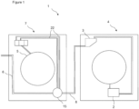
- the laundry washing/drying system (1) comprises a drying machine (4) having a condenser which dehumidifies the drying air and a collection tank (3) wherein the condensate formed in the condenser (2) is collected; a washing machine (7) having a tub (5) wherein the washing process is performed, a mains line (6) through which the mains water is taken and at least one feeding line (22) which carries the water to be delivered to the tub (5); and a delivery line (8) which enables the condensate in the collection tank (3) to be delivered to the washing machine (7).
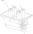
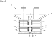
- the laundry washing/drying system (1) of the present invention comprises a water delivery member (15) having a casing (9), a mains water inlet pipe (10) which is provided on the casing (9) and through which the mains water coming from the mains line (6) enters, a condensate inlet pipe (11) which is provided on the casing (9) and through which the condensate coming from the delivery line (8) enters, at least one discharge pipe (17, 18) which is provided on the casing (9) and which is connected to the feeding line (22), a mains water drive wheel (14) which is connected to a shaft (12), which has a plurality of blades (13) thereon and which rotates together with the shaft (12) as the water coming from mains line (6) hits the first blades (13), and a condensate drive wheel (15) which is connected to the shaft (12), which has a plurality of second blades (113) thereon, which rotates with the rotational movement of the shaft (12) so as to move the condensate coming from the delivery line (8)
- the casing (9) forms the body of the water delivery member (15).
- the mains water inlet pipe (10) is provided such that the water coming from the mains line (6) can enter the casing (9).
- the condensate inlet pipe (11) is provided, through which the condensate from the transmission line (8) stored in the collection tank (3) and used for washing the laundry in the tub (5) can enter. Pressurized water passing through the mains water inlet pipe (10) hits the first blade (13) on the mains water drive wheel (14) and rotates the shaft (12) on its own axis, whereon the first blade (13) is located.
- the condensate coming from the delivery line (8) is stationary with the effect of gravity.
- the dynamic pressure of the condensate accumulated in the second blade (113) on the condensate drive wheel (114) is increased with the rotational movement of the shaft (12).
- the dynamic pressure of the condensate coming from the collection tank (3) with the effect of gravity is increased without using a pump.
- the water delivery member (15) has a mains water receptacle (16) which is provided in the casing (9) and which is filled with the mains water coming from the mains line (6), and a condensate receptacle (116) which is provided in the casing (9) and which is filled with the condensate coming from the delivery line (8).
- the mains water and the condensate are filled into separate receptacles so as to prevent them from mixing with each other.
- it is aimed to prevent the reduction of the rotational speed of the shaft (12) and thus the driving power of the water delivery member (15) due to the collection of the high-pressure mains water in the same receptacle with the low-pressure condensate.
- the water delivery member (15) has a first discharge pipe (17) through which the mains water filling the mains water receptacle (16) exits the casing (9) and a second discharge pipe (18) through which the condensate filling the condensate receptacle (116) exits the casing (9). It is provided that the condensate and the mains water exit the water delivery member (15) through separate pipes.
- the diameter values of the first discharge pipe (17) and the second discharge pipe (18) can be changed so as to adjust the dynamic pressures thereof, and pressure loss which would occur in the case an outlet pipe is used is prevented.
- a shaft opening (20) which allows the shaft to pass therethrough and extend from the mains water receptacle (16) to the condensate receptacle (116).
- the rotational movement of the mains water drive wheel (14) and the shaft (12) around its own axis is transferred to the condensate drive wheel (114) located in the condensate receptacle (116).
- At least one sealing member (21) is placed between the shaft opening (20) and the shaft (12).
- the pressure in the mains water is used to send the condensate to the tub (5) at the optimum level.
- the condensate inlet pipe (11) has a larger diameter than the diameter of the second discharge pipe (18).
- the smaller diameter of the second discharge pipe (18) causes the dynamic pressure of the condensate sent from the water delivery member (15) to the tub (5) to be increased, thus enabling the condensate to reach the tub (5) easily.
- the first blade (13) and the second blade (113) have a curved form.
- the curved blade structure increases the water drive power and reduces the noise generated by the water hitting the blades (13, 113).
- the angles of the blades (13, 113) can be changed as desired so as to adjust the dynamic pressure values gained by the mains water and the condensate.
- the transfer of the condensate stored in the drying machine (4) to the tub (5) in the washing machine (7) is provided in a cost-effective manner without using any pump.
Landscapes
- Engineering & Computer Science (AREA)
- Textile Engineering (AREA)
- Mechanical Engineering (AREA)
- General Engineering & Computer Science (AREA)
- Detail Structures Of Washing Machines And Dryers (AREA)
Claims (9)
- Ein Wäschewasch-/Trocknungssystem (1) umfasst eine Trocknungsmaschine (4) mit einem Kondensator, der die Trocknungsluft entfeuchtet, und einem Sammelbehälter (3), in dem das im Kondensator (2) gebildete Kondensat gesammelt wird; eine Waschmaschine (7) mit einer Waschwanne (5), in der der Waschvorgang durchgeführt wird, einer Netzleitung (6), durch die das Netzwasser entnommen wird, und mindestens einer Zuführungsleitung (22), die das der Waschwanne (5) zuzuführende Wasser transportiert; und eine Zuführleitung (8), die es ermöglicht, dass das Kondensat in dem Sammeltank (3) der Waschmaschine (7) zugeführt wird, gekennzeichnet ist durch ein Wasserzuführungselement (15) mit einem Gehäuse (9), einem Hauptwassereinlassrohr (10), das an dem Gehäuse (9) vorgesehen ist und durch das das von der Hauptleitung (6) kommende Hauptwasser eintritt, ein am Gehäuse (9) vorgesehenes Kondensateinlassrohr (11), durch das das von der Druckleitung (8) kommende Kondensat eintritt, mindestens ein am Gehäuse (9) vorgesehenes Abflussrohr (17, 18), das mit der Zuführungsleitung (22) verbunden ist, ein mit einer Welle (12) verbundenes Leitungswasserantriebsrad (14), das mit einer Welle (12) verbunden ist, auf der sich mehrere Schaufeln (13) befinden und das sich zusammen mit der Welle (12) dreht, wenn das von der Netzleitung (6) kommende Wasser auf die ersten Schaufeln (13) trifft, und ein Kondensat-Antriebsrad (114), das mit der Welle (12) verbunden ist, auf der sich mehrere zweite Schaufeln (113) befinden, die sich mit der Drehbewegung der Welle (12) drehen, um das von der Zufuhrleitung (8) kommende Kondensat mittels der zweiten Schaufeln (113) in Richtung auf das Auslassrohr (17, 18) zu bewegen.
- Ein Wäschewasch-/Trocknungssystem (1), wie in Anspruch 1 aufgeführt, ist dadurch gekennzeichnet, dass das Wasserzuführungselement (15), das einen im Gehäuse (9) vorgesehenen Netzwasserbehälter (16), der mit dem von der Netzleitung (6) kommenden Netzwasser gefüllt ist, und einen im Gehäuse (9) vorgesehenen Kondensatbehälter (116), der mit dem von der Zuführungsleitung (8) kommenden Kondensat gefüllt ist, aufweist.
- Ein Wäschewasch-/Trocknungssystem (1), wie in Anspruch 2 aufgeführt, ist dadurch gekennzeichnet, dass das Wasserabgabeelement (15) ein erstes Abflussrohr (17) aufweist, durch das das Leitungswasser, das den Leitungswasserbehälter (16) füllt, das Gehäuse (9) verlässt, und ein zweites Abflussrohr (18), durch das das Kondensat, das den Kondensatbehälter (116) füllt, das Gehäuse (9) verlässt.
- Ein Wäschewasch-/Trocknungssystem (1), wie in Anspruch 2 oder 3 aufgeführt, ist dadurch gekennzeichnet, dass eine Innenwand (19) den Leitungswasserbehälter (16) und den Kondensatbehälter (116) als zwei getrennte Kammern voneinander trennt.
- Ein Wäschewasch-/Trocknungssystem (1), wie in Anspruch 5 aufgeführt, ist dadurch gekennzeichnet, dass eine Schachtöffnung (20) an der Innenwand (19) vorgesehen ist und die es dem Schacht ermöglicht, durch sie hindurchzugehen und sich von dem Hauptwasserbehälter (16) zu dem Kondensatbehälter (116) zu erstrecken.
- Ein Wäschewasch-/Trocknungssystem (1), wie in Anspruch 5 aufgeführt, ist dadurch gekennzeichnet, dass mindestens ein Dichtungselement (21) zwischen der Wellenöffnung (20) und der Welle (12) angeordnet ist.
- Ein Wäschewasch-/Trocknungssystem (1), wie in einem der Ansprüche 3 bis 6 aufgeführt, ist dadurch gekennzeichnet, dass das Kondensateinlassrohr (11) einen größeren Durchmesser als der Durchmesser des zweiten Abflussrohrs (18) aufweist.
- Ein Wäschewasch-/Trocknungssystem (1), wie in einem der vorherigen Ansprüche aufgeführt, ist dadurch gekennzeichnet, dass die erste Klinge (13) und die zweite Klinge (113) eine gekrümmte Form aufweisen.
- Ein Wäschewasch-/Trocknungssystem (1), wie in einem der vorherigen Ansprüche aufgeführt, ist dadurch gekennzeichnet, dass das Kondensat-Antriebsrad (114) mehr zweite Schaufeln (113) als die Anzahl der ersten Schaufeln (13) am Hauptwasser-Antriebsrad (14) aufweist.
Applications Claiming Priority (1)
| Application Number | Priority Date | Filing Date | Title |
|---|---|---|---|
| TR202207783 | 2022-05-13 |
Publications (2)
| Publication Number | Publication Date |
|---|---|
| EP4276231A1 EP4276231A1 (de) | 2023-11-15 |
| EP4276231B1 true EP4276231B1 (de) | 2025-01-01 |
Family
ID=85792109
Family Applications (1)
| Application Number | Title | Priority Date | Filing Date |
|---|---|---|---|
| EP23165464.1A Active EP4276231B1 (de) | 2022-05-13 | 2023-03-30 | Waschtrocknersystem |
Country Status (1)
| Country | Link |
|---|---|
| EP (1) | EP4276231B1 (de) |
Family Cites Families (7)
| Publication number | Priority date | Publication date | Assignee | Title |
|---|---|---|---|---|
| DE69932272T2 (de) | 1998-03-05 | 2007-07-12 | Rockwell International Corp., Thousand Oaks | Optische Verzögerungsschicht |
| KR20020085444A (ko) * | 2001-05-08 | 2002-11-16 | 주식회사 엘지이아이 | 가전기기의 응축수 재생시스템 |
| EP1548173B1 (de) | 2003-12-23 | 2009-07-01 | CANDY S.p.A. | Haushalt-Waschmaschine und Trockner, die miteinander verbunden werden können, entsprechende gemeinsame Installation und entsprechendes Verfahren zum Waschen und Trocknen |
| PL2471994T3 (pl) * | 2011-01-04 | 2019-12-31 | Electrolux Home Products Corporation N.V. | Urządzenie do suszenia materiałów pranych |
| KR102577089B1 (ko) * | 2016-12-27 | 2023-09-12 | 엘지전자 주식회사 | 의류처리장치용 배수펌프 |
| CN110055712A (zh) * | 2018-01-18 | 2019-07-26 | 青岛海尔滚筒洗衣机有限公司 | 一种衣物洗干一体机 |
| KR20200049237A (ko) * | 2018-10-31 | 2020-05-08 | 엘지전자 주식회사 | 세탁기의 펌프 유닛 |
-
2023
- 2023-03-30 EP EP23165464.1A patent/EP4276231B1/de active Active
Also Published As
| Publication number | Publication date |
|---|---|
| EP4276231A1 (de) | 2023-11-15 |
Similar Documents
| Publication | Publication Date | Title |
|---|---|---|
| AU2023200427B2 (en) | Clothes processing apparatus | |
| US3082779A (en) | Dishw ashing machine | |
| EP2398947B1 (de) | Waschmaschine/trockner | |
| WO2019037993A1 (en) | LIQUID DETERGENT DETERGENT UNIT FOR A WASHING MACHINE | |
| EP3015592B1 (de) | Kleiderbehandlungsvorrichtung mit wärmetauscheinheit | |
| EP2423371A1 (de) | Wäschebehandlungsmaschine | |
| EP2363526B1 (de) | Waschmaschine und Laugenpumpe | |
| KR20190128468A (ko) | 의류 처리 장치 | |
| EP2412861B1 (de) | Maschine zum Waschen und Trocknen von Wäsche | |
| KR102776022B1 (ko) | 의류 처리 장치 | |
| KR20190128464A (ko) | 의류 처리 장치 | |
| EP4276231B1 (de) | Waschtrocknersystem | |
| KR100493306B1 (ko) | 드럼세탁기 | |
| KR102776023B1 (ko) | 의류 처리 장치 | |
| CN217817173U (zh) | 烟机结构及空调烟机 | |
| EP2658427B1 (de) | Geschirrspülmaschine mit ozonwaschung | |
| KR20190096727A (ko) | 식기세척기 | |
| KR102568204B1 (ko) | 의류 처리 장치 | |
| TR2022007783A2 (tr) | Bi̇r çamaşir yikama kurutma si̇stemi̇ | |
| EP4310342A1 (de) | Haushaltsgerät mit einer pumpventilanordnung | |
| CN115867698A (zh) | 具有液体环泵的洗涤物护理器具 | |
| WO2007099112A1 (en) | A washing machine | |
| CN222924648U (zh) | 用于清洁装置的驱动泵及衣物处理设备 | |
| CN216427736U (zh) | 衣物处理装置 | |
| CN1318675C (zh) | 洗衣机 |
Legal Events
| Date | Code | Title | Description |
|---|---|---|---|
| PUAI | Public reference made under article 153(3) epc to a published international application that has entered the european phase |
Free format text: ORIGINAL CODE: 0009012 |
|
| STAA | Information on the status of an ep patent application or granted ep patent |
Free format text: STATUS: REQUEST FOR EXAMINATION WAS MADE |
|
| 17P | Request for examination filed |
Effective date: 20230330 |
|
| AK | Designated contracting states |
Kind code of ref document: A1 Designated state(s): AL AT BE BG CH CY CZ DE DK EE ES FI FR GB GR HR HU IE IS IT LI LT LU LV MC ME MK MT NL NO PL PT RO RS SE SI SK SM TR |
|
| REG | Reference to a national code |
Ref country code: DE Free format text: PREVIOUS MAIN CLASS: D06F0029000000 Ipc: F04D0013040000 Ref country code: DE Ref legal event code: R079 Ref document number: 602023001545 Country of ref document: DE Free format text: PREVIOUS MAIN CLASS: D06F0029000000 Ipc: F04D0013040000 |
|
| GRAP | Despatch of communication of intention to grant a patent |
Free format text: ORIGINAL CODE: EPIDOSNIGR1 |
|
| STAA | Information on the status of an ep patent application or granted ep patent |
Free format text: STATUS: GRANT OF PATENT IS INTENDED |
|
| RIC1 | Information provided on ipc code assigned before grant |
Ipc: D06F 58/24 20060101ALI20240715BHEP Ipc: D06F 39/08 20060101ALI20240715BHEP Ipc: D06F 29/00 20060101ALI20240715BHEP Ipc: F04D 13/04 20060101AFI20240715BHEP |
|
| INTG | Intention to grant announced |
Effective date: 20240816 |
|
| GRAS | Grant fee paid |
Free format text: ORIGINAL CODE: EPIDOSNIGR3 |
|
| GRAA | (expected) grant |
Free format text: ORIGINAL CODE: 0009210 |
|
| STAA | Information on the status of an ep patent application or granted ep patent |
Free format text: STATUS: THE PATENT HAS BEEN GRANTED |
|
| AK | Designated contracting states |
Kind code of ref document: B1 Designated state(s): AL AT BE BG CH CY CZ DE DK EE ES FI FR GB GR HR HU IE IS IT LI LT LU LV MC ME MK MT NL NO PL PT RO RS SE SI SK SM TR |
|
| REG | Reference to a national code |
Ref country code: GB Ref legal event code: FG4D |
|
| REG | Reference to a national code |
Ref country code: CH Ref legal event code: EP |
|
| REG | Reference to a national code |
Ref country code: DE Ref legal event code: R096 Ref document number: 602023001545 Country of ref document: DE |
|
| REG | Reference to a national code |
Ref country code: IE Ref legal event code: FG4D |
|
| PGFP | Annual fee paid to national office [announced via postgrant information from national office to epo] |
Ref country code: AT Payment date: 20250417 Year of fee payment: 3 |
|
| REG | Reference to a national code |
Ref country code: LT Ref legal event code: MG9D |
|
| REG | Reference to a national code |
Ref country code: NL Ref legal event code: MP Effective date: 20250101 |
|
| REG | Reference to a national code |
Ref country code: AT Ref legal event code: MK05 Ref document number: 1756503 Country of ref document: AT Kind code of ref document: T Effective date: 20250101 |
|
| PG25 | Lapsed in a contracting state [announced via postgrant information from national office to epo] |
Ref country code: NL Free format text: LAPSE BECAUSE OF FAILURE TO SUBMIT A TRANSLATION OF THE DESCRIPTION OR TO PAY THE FEE WITHIN THE PRESCRIBED TIME-LIMIT Effective date: 20250101 |
|
| PG25 | Lapsed in a contracting state [announced via postgrant information from national office to epo] |
Ref country code: FI Free format text: LAPSE BECAUSE OF FAILURE TO SUBMIT A TRANSLATION OF THE DESCRIPTION OR TO PAY THE FEE WITHIN THE PRESCRIBED TIME-LIMIT Effective date: 20250101 |
|
| PG25 | Lapsed in a contracting state [announced via postgrant information from national office to epo] |
Ref country code: PL Free format text: LAPSE BECAUSE OF FAILURE TO SUBMIT A TRANSLATION OF THE DESCRIPTION OR TO PAY THE FEE WITHIN THE PRESCRIBED TIME-LIMIT Effective date: 20250101 |
|
| PG25 | Lapsed in a contracting state [announced via postgrant information from national office to epo] |
Ref country code: ES Free format text: LAPSE BECAUSE OF FAILURE TO SUBMIT A TRANSLATION OF THE DESCRIPTION OR TO PAY THE FEE WITHIN THE PRESCRIBED TIME-LIMIT Effective date: 20250101 |
|
| PG25 | Lapsed in a contracting state [announced via postgrant information from national office to epo] |
Ref country code: NO Free format text: LAPSE BECAUSE OF FAILURE TO SUBMIT A TRANSLATION OF THE DESCRIPTION OR TO PAY THE FEE WITHIN THE PRESCRIBED TIME-LIMIT Effective date: 20250401 Ref country code: IS Free format text: LAPSE BECAUSE OF FAILURE TO SUBMIT A TRANSLATION OF THE DESCRIPTION OR TO PAY THE FEE WITHIN THE PRESCRIBED TIME-LIMIT Effective date: 20250501 |
|
| PGFP | Annual fee paid to national office [announced via postgrant information from national office to epo] |
Ref country code: IT Payment date: 20250331 Year of fee payment: 3 |
|
| PG25 | Lapsed in a contracting state [announced via postgrant information from national office to epo] |
Ref country code: HR Free format text: LAPSE BECAUSE OF FAILURE TO SUBMIT A TRANSLATION OF THE DESCRIPTION OR TO PAY THE FEE WITHIN THE PRESCRIBED TIME-LIMIT Effective date: 20250101 |
|
| PG25 | Lapsed in a contracting state [announced via postgrant information from national office to epo] |
Ref country code: LV Free format text: LAPSE BECAUSE OF FAILURE TO SUBMIT A TRANSLATION OF THE DESCRIPTION OR TO PAY THE FEE WITHIN THE PRESCRIBED TIME-LIMIT Effective date: 20250101 Ref country code: PT Free format text: LAPSE BECAUSE OF FAILURE TO SUBMIT A TRANSLATION OF THE DESCRIPTION OR TO PAY THE FEE WITHIN THE PRESCRIBED TIME-LIMIT Effective date: 20250502 |
|
| PG25 | Lapsed in a contracting state [announced via postgrant information from national office to epo] |
Ref country code: GR Free format text: LAPSE BECAUSE OF FAILURE TO SUBMIT A TRANSLATION OF THE DESCRIPTION OR TO PAY THE FEE WITHIN THE PRESCRIBED TIME-LIMIT Effective date: 20250402 Ref country code: BG Free format text: LAPSE BECAUSE OF FAILURE TO SUBMIT A TRANSLATION OF THE DESCRIPTION OR TO PAY THE FEE WITHIN THE PRESCRIBED TIME-LIMIT Effective date: 20250101 |
|
| PG25 | Lapsed in a contracting state [announced via postgrant information from national office to epo] |
Ref country code: AT Free format text: LAPSE BECAUSE OF FAILURE TO SUBMIT A TRANSLATION OF THE DESCRIPTION OR TO PAY THE FEE WITHIN THE PRESCRIBED TIME-LIMIT Effective date: 20250101 |
|
| PG25 | Lapsed in a contracting state [announced via postgrant information from national office to epo] |
Ref country code: CZ Free format text: LAPSE BECAUSE OF FAILURE TO SUBMIT A TRANSLATION OF THE DESCRIPTION OR TO PAY THE FEE WITHIN THE PRESCRIBED TIME-LIMIT Effective date: 20250101 |
|
| PG25 | Lapsed in a contracting state [announced via postgrant information from national office to epo] |
Ref country code: SE Free format text: LAPSE BECAUSE OF FAILURE TO SUBMIT A TRANSLATION OF THE DESCRIPTION OR TO PAY THE FEE WITHIN THE PRESCRIBED TIME-LIMIT Effective date: 20250101 |
|
| REG | Reference to a national code |
Ref country code: DE Ref legal event code: R097 Ref document number: 602023001545 Country of ref document: DE |
|
| PG25 | Lapsed in a contracting state [announced via postgrant information from national office to epo] |
Ref country code: SM Free format text: LAPSE BECAUSE OF FAILURE TO SUBMIT A TRANSLATION OF THE DESCRIPTION OR TO PAY THE FEE WITHIN THE PRESCRIBED TIME-LIMIT Effective date: 20250101 |
|
| PG25 | Lapsed in a contracting state [announced via postgrant information from national office to epo] |
Ref country code: DK Free format text: LAPSE BECAUSE OF FAILURE TO SUBMIT A TRANSLATION OF THE DESCRIPTION OR TO PAY THE FEE WITHIN THE PRESCRIBED TIME-LIMIT Effective date: 20250101 |
|
| PG25 | Lapsed in a contracting state [announced via postgrant information from national office to epo] |
Ref country code: MC Free format text: LAPSE BECAUSE OF FAILURE TO SUBMIT A TRANSLATION OF THE DESCRIPTION OR TO PAY THE FEE WITHIN THE PRESCRIBED TIME-LIMIT Effective date: 20250101 |
|
| PG25 | Lapsed in a contracting state [announced via postgrant information from national office to epo] |
Ref country code: EE Free format text: LAPSE BECAUSE OF FAILURE TO SUBMIT A TRANSLATION OF THE DESCRIPTION OR TO PAY THE FEE WITHIN THE PRESCRIBED TIME-LIMIT Effective date: 20250101 |
|
| PG25 | Lapsed in a contracting state [announced via postgrant information from national office to epo] |
Ref country code: RO Free format text: LAPSE BECAUSE OF FAILURE TO SUBMIT A TRANSLATION OF THE DESCRIPTION OR TO PAY THE FEE WITHIN THE PRESCRIBED TIME-LIMIT Effective date: 20250101 |
|
| PG25 | Lapsed in a contracting state [announced via postgrant information from national office to epo] |
Ref country code: SK Free format text: LAPSE BECAUSE OF FAILURE TO SUBMIT A TRANSLATION OF THE DESCRIPTION OR TO PAY THE FEE WITHIN THE PRESCRIBED TIME-LIMIT Effective date: 20250101 |
|
| PLBE | No opposition filed within time limit |
Free format text: ORIGINAL CODE: 0009261 |
|
| STAA | Information on the status of an ep patent application or granted ep patent |
Free format text: STATUS: NO OPPOSITION FILED WITHIN TIME LIMIT |
|
| PG25 | Lapsed in a contracting state [announced via postgrant information from national office to epo] |
Ref country code: LU Free format text: LAPSE BECAUSE OF NON-PAYMENT OF DUE FEES Effective date: 20250330 |
|
| 26N | No opposition filed |
Effective date: 20251002 |
|
| REG | Reference to a national code |
Ref country code: BE Ref legal event code: MM Effective date: 20250331 |
|
| PG25 | Lapsed in a contracting state [announced via postgrant information from national office to epo] |
Ref country code: FR Free format text: LAPSE BECAUSE OF NON-PAYMENT OF DUE FEES Effective date: 20250331 |
|
| PG25 | Lapsed in a contracting state [announced via postgrant information from national office to epo] |
Ref country code: BE Free format text: LAPSE BECAUSE OF NON-PAYMENT OF DUE FEES Effective date: 20250331 |
|
| PG25 | Lapsed in a contracting state [announced via postgrant information from national office to epo] |
Ref country code: IE Free format text: LAPSE BECAUSE OF NON-PAYMENT OF DUE FEES Effective date: 20250330 |
|
| PGFP | Annual fee paid to national office [announced via postgrant information from national office to epo] |
Ref country code: DE Payment date: 20260319 Year of fee payment: 4 |
|
| PGFP | Annual fee paid to national office [announced via postgrant information from national office to epo] |
Ref country code: TR Payment date: 20260306 Year of fee payment: 4 |