EP4275847A1 - Rail storage system with end caps - Google Patents
Rail storage system with end caps Download PDFInfo
- Publication number
- EP4275847A1 EP4275847A1 EP23172250.5A EP23172250A EP4275847A1 EP 4275847 A1 EP4275847 A1 EP 4275847A1 EP 23172250 A EP23172250 A EP 23172250A EP 4275847 A1 EP4275847 A1 EP 4275847A1
- Authority
- EP
- European Patent Office
- Prior art keywords
- end cap
- rail
- left end
- face
- rail assembly
- Prior art date
- Legal status (The legal status is an assumption and is not a legal conclusion. Google has not performed a legal analysis and makes no representation as to the accuracy of the status listed.)
- Granted
Links
Images





Classifications
-
- B—PERFORMING OPERATIONS; TRANSPORTING
- B65—CONVEYING; PACKING; STORING; HANDLING THIN OR FILAMENTARY MATERIAL
- B65G—TRANSPORT OR STORAGE DEVICES, e.g. CONVEYORS FOR LOADING OR TIPPING, SHOP CONVEYOR SYSTEMS OR PNEUMATIC TUBE CONVEYORS
- B65G1/00—Storing articles, individually or in orderly arrangement, in warehouses or magazines
- B65G1/02—Storage devices
-
- A—HUMAN NECESSITIES
- A47—FURNITURE; DOMESTIC ARTICLES OR APPLIANCES; COFFEE MILLS; SPICE MILLS; SUCTION CLEANERS IN GENERAL
- A47F—SPECIAL FURNITURE, FITTINGS, OR ACCESSORIES FOR SHOPS, STOREHOUSES, BARS, RESTAURANTS OR THE LIKE; PAYING COUNTERS
- A47F5/00—Show stands, hangers, or shelves characterised by their constructional features
- A47F5/08—Show stands, hangers, or shelves characterised by their constructional features secured to the wall, ceiling, or the like; Wall-bracket display devices
- A47F5/0807—Display panels, grids or rods used for suspending merchandise or cards supporting articles; Movable brackets therefor
- A47F5/0846—Display panels or rails with elongated channels; Sliders, brackets, shelves, or the like, slidably attached therein
- A47F5/0853—Rail constructions; Brackets
-
- B—PERFORMING OPERATIONS; TRANSPORTING
- B25—HAND TOOLS; PORTABLE POWER-DRIVEN TOOLS; MANIPULATORS
- B25H—WORKSHOP EQUIPMENT, e.g. FOR MARKING-OUT WORK; STORAGE MEANS FOR WORKSHOPS
- B25H3/00—Storage means or arrangements for workshops facilitating access to, or handling of, work tools or instruments
- B25H3/04—Racks
-
- A—HUMAN NECESSITIES
- A47—FURNITURE; DOMESTIC ARTICLES OR APPLIANCES; COFFEE MILLS; SPICE MILLS; SUCTION CLEANERS IN GENERAL
- A47B—TABLES; DESKS; OFFICE FURNITURE; CABINETS; DRAWERS; GENERAL DETAILS OF FURNITURE
- A47B95/00—Fittings for furniture
- A47B95/008—Suspension fittings for cabinets to be hung on walls
-
- A—HUMAN NECESSITIES
- A47—FURNITURE; DOMESTIC ARTICLES OR APPLIANCES; COFFEE MILLS; SPICE MILLS; SUCTION CLEANERS IN GENERAL
- A47B—TABLES; DESKS; OFFICE FURNITURE; CABINETS; DRAWERS; GENERAL DETAILS OF FURNITURE
- A47B96/00—Details of cabinets, racks or shelf units not covered by a single one of groups A47B43/00 - A47B95/00; General details of furniture
- A47B96/06—Brackets or similar supporting means for cabinets, racks or shelves
- A47B96/061—Cantilever brackets
-
- A—HUMAN NECESSITIES
- A47—FURNITURE; DOMESTIC ARTICLES OR APPLIANCES; COFFEE MILLS; SPICE MILLS; SUCTION CLEANERS IN GENERAL
- A47B—TABLES; DESKS; OFFICE FURNITURE; CABINETS; DRAWERS; GENERAL DETAILS OF FURNITURE
- A47B96/00—Details of cabinets, racks or shelf units not covered by a single one of groups A47B43/00 - A47B95/00; General details of furniture
- A47B96/06—Brackets or similar supporting means for cabinets, racks or shelves
- A47B96/067—Horizontal rails as suspension means in a cantilever arrangement
-
- A—HUMAN NECESSITIES
- A47—FURNITURE; DOMESTIC ARTICLES OR APPLIANCES; COFFEE MILLS; SPICE MILLS; SUCTION CLEANERS IN GENERAL
- A47F—SPECIAL FURNITURE, FITTINGS, OR ACCESSORIES FOR SHOPS, STOREHOUSES, BARS, RESTAURANTS OR THE LIKE; PAYING COUNTERS
- A47F5/00—Show stands, hangers, or shelves characterised by their constructional features
- A47F5/08—Show stands, hangers, or shelves characterised by their constructional features secured to the wall, ceiling, or the like; Wall-bracket display devices
- A47F5/0807—Display panels, grids or rods used for suspending merchandise or cards supporting articles; Movable brackets therefor
- A47F5/0838—Rails or bars; Article supports therefor, e.g. brackets being slidably attached on the outside thereof
-
- A—HUMAN NECESSITIES
- A47—FURNITURE; DOMESTIC ARTICLES OR APPLIANCES; COFFEE MILLS; SPICE MILLS; SUCTION CLEANERS IN GENERAL
- A47F—SPECIAL FURNITURE, FITTINGS, OR ACCESSORIES FOR SHOPS, STOREHOUSES, BARS, RESTAURANTS OR THE LIKE; PAYING COUNTERS
- A47F5/00—Show stands, hangers, or shelves characterised by their constructional features
- A47F5/08—Show stands, hangers, or shelves characterised by their constructional features secured to the wall, ceiling, or the like; Wall-bracket display devices
- A47F5/0807—Display panels, grids or rods used for suspending merchandise or cards supporting articles; Movable brackets therefor
- A47F5/0846—Display panels or rails with elongated channels; Sliders, brackets, shelves, or the like, slidably attached therein
-
- B—PERFORMING OPERATIONS; TRANSPORTING
- B65—CONVEYING; PACKING; STORING; HANDLING THIN OR FILAMENTARY MATERIAL
- B65G—TRANSPORT OR STORAGE DEVICES, e.g. CONVEYORS FOR LOADING OR TIPPING, SHOP CONVEYOR SYSTEMS OR PNEUMATIC TUBE CONVEYORS
- B65G1/00—Storing articles, individually or in orderly arrangement, in warehouses or magazines
- B65G1/02—Storage devices
- B65G1/026—Racks equipped with a displaceable load carrying surface to facilitate loading or unloading
Definitions
- the present disclosure relates generally to a rail storage system, and more particularly, to end caps for the rail storage system.
- Rail storage systems typically comprise a wall mountable rail, and accessories that connect to the rail. Such systems may be used in a garage or other similar area. The accessories are designed to hold a wide variety of consumer items such as tools, bicycles, hoses, sports equipment and other consumer articles.
- One disadvantage with such rail storage systems results from not having sufficient spacing between adjacent rails, in either the horizontal direction, vertical direction, or both. Without sufficient spacing between adjacent rails, the rail storage system may have insufficient spacing to use accessories such as hooks, baskets, etc. Moreover, insufficient spacing between rails in a rail storage system can result in improper weight distribution over a walled surface.
- a storage rail assembly includes a first rail configured to be coupled to a wall.
- the first rail extends from a left end to a right end along a first longitudinal axis.
- the assembly further includes a first left end cap coupled to the left end of the rail, the left end cap including a concave pocket extending inwardly from a left face of the first left end cap and having a pocket contact surface; and a right end cap coupled to the right end of the rail, the right end cap including a projection extending outwardly from a right face of the right end cap, wherein the projection is configured to be received in a pocket of a second left end cap to form a horizontal rail assembly.
- an end cap system for a storage rail assembly includes a first end cap including a body having a side face, an outer face, and a wall face, and a hollow interior defined by the outer face, the side face, and the wall face.
- the side face includes a first alignment feature configured to be complementary to a second alignment feature of a second end cap adjacent to the first end cap.
- the storage rail is configured to be received within the hollow interior of the first end cap.
- the terms “first”, “second”, and “third” may be used interchangeably to distinguish one component from another and are not intended to signify location or importance of the individual components.
- the singular forms “a,” “an,” and “the” include plural references unless the context clearly dictates otherwise.
- the terms “coupled,” “fixed,” “attached to,” and the like refer to both direct coupling, fixing, or attaching, as well as indirect coupling, fixing, or attaching through one or more intermediate components or features, unless otherwise specified herein.
- the terms “comprises,” “comprising,” “includes,” “including,” “has,” “having” or any other variation thereof, are intended to cover a non-exclusive inclusion.
- a process, method, article, or apparatus that comprises a list of features is not necessarily limited only to those features but may include other features not expressly listed or inherent to such process, method, article, or apparatus.
- "or" refers to an inclusive- or and not to an exclusive- or. For example, a condition A or B is satisfied by any one of the following: A is true (or present) and B is false (or not present), A is false (or not present) and B is true (or present), and both A and B are true (or present).
- FIG. 1 illustrates an exemplary rail assembly 10 that may be part of a larger storage system 11 (e.g., for a garage) to support storage accessories.
- the rail assembly 10 is coupled to a vertical wall 12, for instance, in a garage or other workspace, adjacent other rail assemblies 10a-10h.
- Accessories including, for instance, a shelf 13a, basket 13b, hooks 13c, a single-battery holder 13d, or a multiple-battery holder 13e, may be coupled to the rail assembly 10.
- the accessories may engage the rail assembly 10 in a snapped engagement or other coupling arrangement.
- FIG. 2 illustrates an exemplary rail assembly 10.
- the rail assembly 10 includes a rail 14, a left end cap 18, and a right end cap 22.
- the rail 14 has a mounting face 23 that extends along a longitudinal axis A between a left end 26 and a right end 30.
- the rail 14 includes and top and bottom flanges 24, 25 extending along the upper edge and lower edge of the rail 14 on the top and bottom sides, respectively, of the mounting face 23 and also extending between the left end 26 and right end 30.
- the rail 14 may have a length in a range from about 15 inches to about 50 inches, such as from about 30 inches to about 40 inches, for instance, a length of about thirtyfive inches, between the left end 26 and right end 30, or another appropriate length.
- the rail 14 may be coupled to the wall 12 using fasteners (not shown) inserted through holes 38 that are spaced equidistantly, for instance, two inches apart or any other desirable spacing, along the top and bottom flanges 24, 25.
- the rail 14 may include a pegboard, that is, pairs of holes 40 spaced equidistantly along the mounting face 23.
- FIG. 3 illustrates a rail 14 with no left end cap 18 or right end cap 22.
- the left end 26 has an exposed left open end 26a
- the right end 30 has an exposed right open end 30a.
- the rail 14 includes a trough 42 and a peak 44 with an interior 46 that extend along the longitudinal axis A between the mounting face 23 and the top flange 24.
- the rail 14 also includes a crease 48 that extends along the longitudinal axis A between the mounting face 23 and the bottom flange 25.
- the left end 26 and right end 30 of the rail 14 define a left open end 26a and a right open end 30a.
- the left end cap 18 is coupled to the left end 26 of the rail 14 and supports the rail 14 relative to adjacent rail assemblies 10.
- the left end cap 18 encloses the left open end 26a.
- the right end cap 22 is coupled to the right end 30 of the rail 14 and supports the right end 30 of the rail 14 relative to adjacent rail assemblies 10.
- the right end cap 22 is inserted into and encloses the right open end 30a of the rail 14.
- the left end cap 18 and right end cap 22 include alignment features 50 that interact to align, support, and distribute the weight of the rail assemblies 10.
- the alignment features 50 interact to align the axes A of horizontally adjacent rail assemblies 10.
- the right end cap 22 of the rail assembly 10a includes a projection 54 that is received in a pocket 58 of the left end cap 18 of a horizontally adjacent rail assembly 10b, which interlock the horizontally adjacent rail assemblies 10.
- the alignment features 50 also vertically space the rails 14 of vertically adjacent rail assemblies 10 and generally evenly distribute the weight of the rail assemblies 10.
- the alignment features 50 also include first and second contact faces 60, 64 of the left end cap 18 and first and second contact faces 68, 72 of the right end cap 22. As illustrated in FIG. 5 , the alignment features 50 vertically space the rail assemblies 10 to allow use of accessories on vertically adjacent rail assemblies 10 with limited or no interference between accessories, such as vertically stacked hooks 13c or battery holders 13d, 13e.
- the illustrated left end cap 18 has a parallelogram shape and includes a left face 82 (side face), an opposite right face 86 ( FIG. 9 ), a wall face 88, and an outer face 92.
- the wall face 88 is positioned adjacent the wall 12 when the rail assembly 10 is coupled to the wall 12 and the outer face 92 is spaced from the wall 12.
- the left end cap 18 also includes a first contact face 60 (upper contact face) and second contact face 64 (lower contact face). When the rail assembly 10 is coupled to a wall, the first contact face 60 is positioned in a direction vertically above of the second contact face 64, as viewed by the user.
- the first contact face 60 extends at an angle 96 relative to the outer face in a direction downward and inward toward the center of the left end cap 18 to form an upper acute angle.
- the angle 96 may be an acute angle.
- the angle 96 may be in a range from about 10 degrees to about 80 degrees, such as from about 15 degrees to about 75 degrees, for instance from about 25 degrees to about 65 degrees.
- the second contact face 64 extends from the wall face 88 to the outer face 92 in a direction upward and inward at an angle 100 to form a lower acute angle that may be equivalent to the angle 96 of the first contact face 60. While the left end cap 18 is illustrated as having a parallelogram shape, the left end cap may have a different shape.
- the point of the parallelogram of the first rail assembly 10 which is defined by the second contact face 64, may nest with the second rail assembly 10.
- the first contact face 60 and the second contact face 64 may contact each other.
- the left face 82 includes a pocket 58 extending inwardly from the left face 82 along an exterior of the left end cap 18, and that has an inner surface 122, also referred to as a pocket contact surface.
- the pocket 58 forms a concave recess (concave pocket) on the left face 82 of the left end cap 18.
- the pocket 58 may be disposed adjacent to the wall face 88 of the left end cap 18.
- the inner surface 122 may be prismatic and divided into different surface portions 122a, 122b, 122c. In other constructions, the inner surface 122 may be curved.
- the pocket 58 may have other geometric relationships.
- the particular geometry of the pocket 58 is not critical as long as the shape and size of the pocket 58 is a concave recess that is configured to receive a projection 54 from a right end cap 22 therein.
- the size and shape of the pocket 58 may be complementary to the size and shape of the projection 54.
- the left end cap 18 has a hollow interior 134 and a lattice 138 extending from an interior side 142 of the left face 82 toward the right face 86.
- the lattice 138 has a lattice face 146 that is offset from the right face 86 in a direction toward the left face 82, i.e., within the hollow interior 134.
- the lattice face 146 abuts the open left end 26a of the rail 14 whereby the left end cap 18 overlaps the left end 26 of the rail 14.
- the left end cap 18 further includes a rib 140 extending from an interior side 142 of the left face 82 toward the right face 86.
- the rib 140 is disposed between the first contact face 60 and the protrusion 174 (described below).
- the rib 140 may provide additional structural integrity and stability to the left end cap 18 in an assembled state of the storage rail assembly 10. Additionally, the rib 140 may prevent the rail 14 from sliding upward toward the first contact face 60 when the rail 14 is coupled with the left end cap 18, thereby aiding in maintaining spacing between vertically adjacent rails 14.
- the rib 140 may be spaced a distance R from the first contact face 60 when measured along the outer surface 92.
- the left end cap 18 may be coupled to the rail 14 by a rail mount extension 150.
- the rail mount extension 150 extends from the interior side 142 of the left face 82 toward and beyond the right face 86.
- the rail mount extension 150 defines a first portion 154, a second portion 158, and first and second bridges 162, 166 joining the first portion 154 and second portion 158.
- the first and second bridges 162, 166 extend from the first portion 154 to the second portion 158 and include cutouts 170a, 17b, 17c, 170d adjacent the first portion 154 and second portion 158.
- a protrusion 174 extends from the first portion 154 adjacent the first bridge 162 away from the second portion 158 and in a direction generally perpendicular to the axis A.
- the second portion 158 includes an arcuate recess 178.
- the rail mount extension 150 When the left end cap 18 is coupled to the rail 14, the rail mount extension 150 is disposed in the left open end 26a of the rail 14.
- the protrusion 174 is configured to be disposed in the interior 46 of the peak 44 of the rail 14.
- the top flange 24 is configured to be disposed behind the protrusion 174, i.e., closer to the wall 12, when the rail assembly 10 is mounted to the wall 12.
- the crease 48 of the rail 14 is configured to be nested with the recess 178 of the second portion 158.
- the first portion 154 and second portion 158 of the rail mount extension 150 are frictionally engaged with the top flange 24 and bottom flange 25 of the rail 14.
- the cutouts 170a-d permit flexing of the first and second portions 154, 158 which permit insertion of the rail mount extension 150 through the left open end 26a.
- the protrusion 174 is a poke yoke feature that prevents the left end cap 18 from being coupled to the right open end 30a of the rail 14.
- the protrusion 174 is configured to prevent inadvertent improper assembly of the rail assembly 10. If the right open end 30a of the rail 14 is attempted to be coupled with the left end cap 18, i.e., with the rail 14 disposed upside down with the bottom flange 25 facing upward, the protrusion 174 would interfere with the bottom flange 25 of the rail 14 to prevent insertion of the right open end 30a into the left end cap 18.
- FIGS. 11-15 illustrate the body of the right end cap 22, which has a parallelogram shape and includes a right face 182 (side face), an opposite left face 186 ( FIG. 14 ), a wall face 188 and an outer face 192.
- the wall face 188 is positioned adjacent the wall 12 when the rail assembly 10 is coupled to the wall 12 and the outer face 192 is spaced from the wall 12.
- the right end cap 22 also includes a first contact face 68 (upper contact face) and second contact face 72 (lower contact face). When the rail assembly 10 is coupled to a wall, the first contact face 68 may be positioned in a direction vertically above of the second contact face 72, as viewed by the user.
- the first contact face 68 extends at an angle 196 relative to the outer face 192 in a direction downward and inward toward the center of the right end cap 22 to form an upper acute angle.
- the angle 196 may be an acute angle.
- the angle 196 may be in a range from about 10 degrees to about 80 degrees, such as from about 15 degrees to about 75 degrees, for instance from about 25 degrees to about 65 degrees.
- the second contact face 72 extends from the wall face 188 to the outer face 192 in a direction upward and inward at an angle 200 to form a lower acute angle that may be equivalent to the angle 196 of the first contact face 68. While the right end cap 22 is illustrated as having a parallelogram shape, the right end cap 22 may have a different geometric shape.
- the point of the parallelogram of the first rail assembly 10a ( FIG. 4 ), which is defined by the second contact face 72, will nest in the second rail assembly 10b.
- the first contact face 68 and the second contact face 72 may contact each other.
- a projection 54 extends outwardly from the right face 182.
- the projection 54 may be adjacent to and extend from the wall face 188 of the right end cap 22.
- the projection 54 has an outer surface 222, also referred to as a projection contact surface.
- the outer surface 222 may be prismatic and divided into different surface portions 222a, 222b, 222c. In other constructions, the outer surface 222 may be curved.
- the projection 54 may have other geometric relationships. As described in further detail below, the particular geometry of the projection 54 is not critical as long as the shape and size of the projection 54 is configured to fit within a pocket 58 of a left end cap 18 therein. In some aspects of the present invention, the size and shape of the projection 54 may be complementary to the size and shape of the pocket 58.
- the projection 54 of the right end cap 22 and pocket 58 of the left end cap 18 form alignment features 50.
- the pocket 58 may be shaped to receive the projection 54 when at least two rail assemblies 10 are coupled to a wall 12 horizontally adjacent one another, as illustrated in, e.g., FIG. 4 .
- the right end cap 22 has a hollow interior 234 and a lattice 238 extending from an interior side 242 of the right face 182 toward the left face 186.
- the lattice 238 has a lattice face 246 that is offset from the left face 186 in a direction toward the right face 182, i.e., in the hollow interior 234.
- the lattice face 246 is configured to abut the right end 30 of the rail 14 and the right end cap 22 overlaps the right end 30 of the rail 14.
- the right end cap 22 further includes a rib 240 extending from an interior side 242 of the right face 182 toward the left face 186.
- the rib 240 is disposed between the first contact face 68 and the protrusion 274 (described below).
- the rib 240 may provide additional structural integrity and stability to the right end cap 22 in an assembled state of the storage rail assembly 10. Additionally, the rib 240 may prevent the rail 14 from sliding upward toward the first contact face 68 when the rail 14 is coupled with the right end cap 22, thereby aiding in maintaining spacing between vertically adjacent rails 14.
- the rib 240 may be spaced a distance R from the first contact face 68 when measured along the outer surface 192.
- the right end cap 22 may be coupled to the rail 14 by a rail mount extension 250.
- the rail mount extension 250 extends from the interior side 242 of the right face 182 toward and beyond the left face 186.
- the rail mount extension 250 defines a first portion 254, a second portion 258, a first bridge 262 and a second bridge 266.
- the first and second bridges 262, 266 extend from the first portion 254 to the second portion 258 and include cutouts 270a-270d adjacent the first portion 254 and second portion 258.
- a protrusion 274 extends from the first portion 254 adjacent the first bridge 264 in a direction away from the second portion 258.
- the second portion 258 includes an arcuate recess 278.
- the rail mount extension 250 When the right end cap 22 is coupled to the right end 30 of the rail 14, the rail mount extension 250 is disposed in the right open end 30a at the right end 30 of the rail 14.
- the protrusion 274 is disposed in the interior 46 of the peak 44.
- the protrusion 274 prevents the right end cap 22 from being coupled to the left end 26 of the rail 14, as the protrusion 274 would interfere with the bottom flange 25 of the rail 14.
- the crease 48 of the rail 14 is nested with the recess 278 of the second portion 258.
- the first portion 254 and second portion 258 of the right end cap 22 are frictionally engaged with the top flange 24 and bottom flange 25 of the rail 14.
- the cutouts 270a-d permit the first portion 254 and second portion 258 of the rail mount extension 250 to flex when the rail mount extension 250 is inserted into the right open end 30a.
- the protrusion 274 is a poka yoke feature that prevents the right end cap 22 from being coupled to the left open end 26a of the rail 14.
- the protrusion 274 is configured to prevent inadvertent improper assembly of the rail assembly 10. If the left open end 26a of the rail 14 is attempted to be coupled with the right end cap 22, i.e., with the rail 14 disposed upside down with the bottom flange 25 facing upward, the protrusion 274 would interfere with the bottom flange 25 of the rail 14 to prevent insertion of the left open end 26a into the right end cap 22.
- a storage system 11 including a plurality of rail assemblies 10 is illustrated.
- a first rail assembly 10a, second rail assembly 10b, third rail assembly 10c, and fourth rail assembly 10d are mounted to wall 12 in a vertical orientation, with the first rail assembly 10a disposed at a highest height and the fourth rail assembly 10d disposed at a lowest height.
- the second contact face 64 of the left end cap 18 of rail assembly 10a (first rail assembly) aligns with and contacts the first contact face 60 of the left end cap 18 of rail assembly 10b (second rail assembly) disposed vertically adjacent below rail assembly 10a.
- the second contact face 72 of the right end cap 22 of rail assembly 10a aligns with and contacts the first contact face 68 of the right end cap 22 of rail assembly 10b disposed vertically adjacent below rail assembly 10a.
- each of the rails 14 that are disposed vertically adjacent above or below each other are spaced by a distance D.
- the distance D is at least as long as the distance R of each of the left end cap 18 and right end cap 22, i.e., a distance between the ribs 140, 240 and the first contact faces 60, 68 along the outer surfaces 92, 192 of the left end cap 18 and right end cap 22, respectively.
- the distance D can be in a range from about 1 cm to about 20 cm including any incremental distance therebetween.
- the spacing distance D is at least as long as a projection of any of the accessories 13a-e above or below a rail 14 when coupled to the rail 14, e.g., as illustrated in FIG. 1 .
- the single battery holder 13d and/or multiple battery holder 13e may extend above or below each of the rails 14 when coupled with the storage rail assembly 10 to an extent that is less than or equal to the distance D.
- a fifth rail assembly 10e, a sixth rail assembly 10f, a seventh rail assembly 10g, and an eighth rail assembly 10h are mounted to wall 12 in a vertical orientation.
- first rail assembly 10a and the fifth rail assembly 10e are mounted to the wall 12 horizontally adjacent to each other such that the first rail assembly 10a and the fifth rail assembly 10e share a longitudinal axis A and form a horizontal rail assembly.
- the right end cap 22 of rail assembly 10a is adjacent to, and may contact, the left end cap 18 of rail assembly 10e.
- the right face 182 of the right end cap 22 may contact the left face 82 of the left end cap 18.
- the projection 54 of the right end cap 22 may be inserted within the pocket 58 of the adjacent left end cap 18. More particularly, the surface portions 222a, 222b, 222c of the projection 54 may align with and/or come into contact with the surface portions 122a, 122b, 122c of the pocket 58.
- the right end cap 22 and left end cap 18 may be aligned in parallel along the axis A, and as a result, the respective horizontally adjacent rails 14 may be aligned in parallel along the axis A.
- the outer surface 92 of the left end cap 18 and the outer surface 192 of the right end cap 22 may form a generally coplanar surface, with the projection 54 and pocket 58 aligning along the wall surfaces 88, 188 of the left end cap 18 and right end cap 22.
- the second and sixth rail assemblies 10b and 10f, third and seventh rail assemblies 10c and 10g, and fourth and eighth rail assemblies 10d and 10h are similarly mounted horizontally adjacent to each other as described above with regard to the first and fifth rail assemblies 10a, 10e to form a series of parallel horizontal rail assemblies.
- the storage system 11 illustrated FIG. 1 four rows of two rail assemblies 10 each are formed.
- each of the rail assemblies 10a-h are mounted to form parallel, level rows having equal (equidistant) spacing between each.
- a storage rail assembly includes a first rail configured to be coupled to a wall.
- the first rail extends from a left end to a right end along a first longitudinal axis.
- the assembly further includes a first left end cap coupled to the left end of the rail, the left end cap including a concave pocket extending inwardly from a left face of the first left end cap and having a pocket contact surface; and a right end cap coupled to the right end of the rail, the right end cap including a projection extending outwardly from a right face of the right end cap, wherein the projection is configured to be received in a pocket of a second left end cap to form a horizontal rail assembly.
- the projection has a projection contact surface, wherein the projection contact surface is configured to align with a pocket contact surface of the pocket of the second left end cap.
- the second left end cap and the right end cap each comprise a wall surface configured to be disposed adjacent to the wall and an outer surface parallel to the respective wall surface, wherein when the projection is received within the pocket of the second left end cap, the outer surface of the second left end cap and the outer surface of the right end cap are configured to be coplanar.
- first left end cap includes a first contact face and a second contact face, wherein the first contact face of the first left end cap is configured to contact a second contact face of a third left end cap such that the first left end cap and the third left end cap are vertically aligned.
- the storage rail assembly of any one or more of the embodiments wherein the third left end cap is coupled to a left open end of a second rail, wherein the second rail extends from the left open end to a right end along a second longitudinal axis that is parallel to the first longitudinal axis.
- the storage rail assembly of any one or more of the embodiments wherein the first rail and the second rail are spaced apart by a distance D in a direction perpendicular to the first longitudinal axis and the second longitudinal axis.
- the storage rail assembly of any one or more of the embodiments further comprising an accessory mounted to one of the first rail or the second rail, wherein the accessory extends into a space between the first rail and the second rail in a vertical direction.
- first contact face and the second contact face of the first left end cap are configured to be disposed at an acute angle relative to the wall when the first left end cap is mounted parallel to the wall.
- first left end cap comprises a hollow interior, wherein the left end of the first rail is configured to be received within the hollow interior.
- first left end cap comprises a rail mount extension disposed in the hollow interior of the left end cap, wherein the rail mount extension is coupled to a left open end of the rail.
- the rail mount extension comprises a poke yoke feature configured to prevent improper coupling between the first left end cap and the end of the rail.
- the rail comprises a mounting face configured to be disposed parallel to the wall and extending between an upper edge and a lower edge, and a trough disposed between the upper edge and the mounting face, further wherein the rail mount extension comprises a projection configured to extend within the trough when the first left end cap and the first rail are coupled, wherein the projection of the rail mount extension is the poke yoke feature.
- An end cap system for a storage rail assembly includes a first end cap including a body having a side face, an outer face, and a wall face, and a hollow interior defined by the outer face, the side face, and the wall face.
- the side face includes a first alignment feature configured to be complementary to a second alignment feature of a second end cap adjacent to the first end cap.
- the storage rail is configured to be received within the hollow interior of the first end cap.
- the end cap system of any one or more of the embodiments further comprising an upper contact face and a lower contact face, wherein each of the upper contact face and the lower contact face extend from the outer face to the wall face.
- the end cap system of any one or more of the embodiments further comprising a rail mount extension disposed within the hollow interior of the first end cap, wherein the rail mount extension comprises a poke yoke feature configured to prevent improper coupling between the storage rail and the rail mount extension.
Landscapes
- Engineering & Computer Science (AREA)
- Mechanical Engineering (AREA)
- Fittings On The Vehicle Exterior For Carrying Loads, And Devices For Holding Or Mounting Articles (AREA)
- Bearings For Parts Moving Linearly (AREA)
Abstract
Description
- The present application claims priority to
US Provisional Patent Application No. 63/341,815 filed on May 13, 2022 - The present disclosure relates generally to a rail storage system, and more particularly, to end caps for the rail storage system.
- Rail storage systems typically comprise a wall mountable rail, and accessories that connect to the rail. Such systems may be used in a garage or other similar area. The accessories are designed to hold a wide variety of consumer items such as tools, bicycles, hoses, sports equipment and other consumer articles. One disadvantage with such rail storage systems results from not having sufficient spacing between adjacent rails, in either the horizontal direction, vertical direction, or both. Without sufficient spacing between adjacent rails, the rail storage system may have insufficient spacing to use accessories such as hooks, baskets, etc. Moreover, insufficient spacing between rails in a rail storage system can result in improper weight distribution over a walled surface.
- Accordingly, improved rail storage assemblies are desired in the art. In particular, rail storage assemblies which provide horizontal and vertical spacing between rails would be advantageous.
- Aspects and advantages of the invention in accordance with the present disclosure will be set forth in part in the following description, or may be obvious from the description, or may be learned through practice of the technology.
- In accordance with one embodiment, a storage rail assembly is provided. The storage rail assembly includes a first rail configured to be coupled to a wall. The first rail extends from a left end to a right end along a first longitudinal axis. The assembly further includes a first left end cap coupled to the left end of the rail, the left end cap including a concave pocket extending inwardly from a left face of the first left end cap and having a pocket contact surface; and a right end cap coupled to the right end of the rail, the right end cap including a projection extending outwardly from a right face of the right end cap, wherein the projection is configured to be received in a pocket of a second left end cap to form a horizontal rail assembly.
- In accordance with another embodiment, an end cap system for a storage rail assembly is provided. The end cap system includes a first end cap including a body having a side face, an outer face, and a wall face, and a hollow interior defined by the outer face, the side face, and the wall face. The side face includes a first alignment feature configured to be complementary to a second alignment feature of a second end cap adjacent to the first end cap. The storage rail is configured to be received within the hollow interior of the first end cap.
- These and other features, aspects and advantages of the present invention will become better understood with reference to the following description and appended claims. The accompanying drawings, which are incorporated in and constitute a part of this specification, illustrate embodiments of the technology and, together with the description, serve to explain the principles of the technology.
- A full and enabling disclosure of the present invention, including the best mode of making and using the present systems and methods, directed to one of ordinary skill in the art, is set forth in the specification, which makes reference to the appended figures, in which:
-
FIG. 1 is a perspective view of a rail storage system including a plurality of rail assemblies and accessories coupled to the rail assemblies. -
FIG. 2 is a perspective view of a rail assembly including a rail, a left end cap coupled to a left end of the rail, and a right end cap coupled to a right end of the rail. -
FIG. 3 is a perspective view of the rail ofFIG. 2 . -
FIG. 4 is a top view of a portion of rail storage system ofFIG. 1 illustrating the interaction between left and right end caps. -
FIG. 5 is an enlarged perspective view of the rail storage system ofFIG. 1 . -
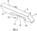
FIG. 6 is a perspective view of the left end cap ofFIG. 2 . -
FIG. 7 is a left side view of the left end cap ofFIG 6 . -
FIG. 8 is a bottom side view of the left end cap ofFIG. 6 . -
FIG. 9 is another perspective view of the left end cap ofFIG. 6 illustrating the right side of the left end cap. -
FIG. 10 is a right side view of the left end cap ofFIG. 6 . -
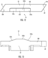
FIG. 11 is a perspective view of the right end cap ofFIG. 2 . -
FIG. 12 is a right side view of a right end cap ofFIG. 11 . -
FIG. 13 is a bottom side view of the right end cap ofFIG. 11 . -
FIG. 14 is a perspective view of a left side of the right end cap ofFIG. 11 . -
FIG. 15 is a left side view of the right end cap ofFIG. 11 . - Reference now will be made in detail to embodiments of the present invention, one or more examples of which are illustrated in the drawings. The word "exemplary" is used herein to mean "serving as an example, instance, or illustration." Any implementation described herein as "exemplary" is not necessarily to be construed as preferred or advantageous over other implementations. Moreover, each example is provided by way of explanation, rather than limitation of, the technology. In fact, it will be apparent to those skilled in the art that modifications and variations can be made in the present technology without departing from the scope or spirit of the claimed technology. For instance, features illustrated or described as part of one embodiment can be used with another embodiment to yield a still further embodiment. Thus, it is intended that the present disclosure covers such modifications and variations as come within the scope of the appended claims and their equivalents. The detailed description uses numerical and letter designations to refer to features in the drawings. Like or similar designations in the drawings and description have been used to refer to like or similar parts of the invention.
- As used herein, the terms "first", "second", and "third" may be used interchangeably to distinguish one component from another and are not intended to signify location or importance of the individual components. The singular forms "a," "an," and "the" include plural references unless the context clearly dictates otherwise. The terms "coupled," "fixed," "attached to," and the like refer to both direct coupling, fixing, or attaching, as well as indirect coupling, fixing, or attaching through one or more intermediate components or features, unless otherwise specified herein. As used herein, the terms "comprises," "comprising," "includes," "including," "has," "having" or any other variation thereof, are intended to cover a non-exclusive inclusion. For example, a process, method, article, or apparatus that comprises a list of features is not necessarily limited only to those features but may include other features not expressly listed or inherent to such process, method, article, or apparatus. Further, unless expressly stated to the contrary, "or" refers to an inclusive- or and not to an exclusive- or. For example, a condition A or B is satisfied by any one of the following: A is true (or present) and B is false (or not present), A is false (or not present) and B is true (or present), and both A and B are true (or present).
- Terms of approximation, such as "about," "generally," "approximately," or "substantially," include values within ten percent greater or less than the stated value. When used in the context of an angle or direction, such terms include within ten degrees greater or less than the stated angle or direction. For example, "generally vertical" includes directions within ten degrees of vertical in any direction, e.g., clockwise or counter-clockwise.
- Benefits, other advantages, and solutions to problems are described below with regard to specific embodiments. However, the benefits, advantages, solutions to problems, and any feature(s) that may cause any benefit, advantage, or solution to occur or become more pronounced are not to be construed as a critical, required, or essential feature of any or all the claims.
- Referring now to the drawings,
FIG. 1 illustrates anexemplary rail assembly 10 that may be part of a larger storage system 11 (e.g., for a garage) to support storage accessories. Therail assembly 10 is coupled to avertical wall 12, for instance, in a garage or other workspace, adjacent other rail assemblies 10a-10h. Accessories including, for instance, ashelf 13a,basket 13b, hooks 13c, a single-battery holder 13d, or a multiple-battery holder 13e, may be coupled to therail assembly 10. The accessories may engage therail assembly 10 in a snapped engagement or other coupling arrangement. -
FIG. 2 illustrates anexemplary rail assembly 10. Therail assembly 10 includes arail 14, aleft end cap 18, and aright end cap 22. Therail 14 has a mountingface 23 that extends along a longitudinal axis A between aleft end 26 and aright end 30. Therail 14 includes and top andbottom flanges rail 14 on the top and bottom sides, respectively, of the mountingface 23 and also extending between theleft end 26 andright end 30. Therail 14 may have a length in a range from about 15 inches to about 50 inches, such as from about 30 inches to about 40 inches, for instance, a length of about thirtyfive inches, between theleft end 26 andright end 30, or another appropriate length. Therail 14 may be coupled to thewall 12 using fasteners (not shown) inserted throughholes 38 that are spaced equidistantly, for instance, two inches apart or any other desirable spacing, along the top andbottom flanges rail 14 may include a pegboard, that is, pairs ofholes 40 spaced equidistantly along the mountingface 23. -
FIG. 3 illustrates arail 14 with noleft end cap 18 orright end cap 22. Theleft end 26 has an exposed left open end 26a, and theright end 30 has an exposed rightopen end 30a. Additionally, as best seen inFIG. 3 , therail 14 includes atrough 42 and a peak 44 with an interior 46 that extend along the longitudinal axis A between the mountingface 23 and thetop flange 24. Therail 14 also includes acrease 48 that extends along the longitudinal axis A between the mountingface 23 and thebottom flange 25. Theleft end 26 andright end 30 of therail 14 define a left open end 26a and a rightopen end 30a. - As shown in
FIG. 4 , in arail assembly 10, theleft end cap 18 is coupled to theleft end 26 of therail 14 and supports therail 14 relative toadjacent rail assemblies 10. In this regard, theleft end cap 18 encloses the left open end 26a. Theright end cap 22 is coupled to theright end 30 of therail 14 and supports theright end 30 of therail 14 relative toadjacent rail assemblies 10. Theright end cap 22 is inserted into and encloses the rightopen end 30a of therail 14. - The
left end cap 18 andright end cap 22 include alignment features 50 that interact to align, support, and distribute the weight of therail assemblies 10. The alignment features 50 interact to align the axes A of horizontallyadjacent rail assemblies 10. More particularly, theright end cap 22 of the rail assembly 10a includes aprojection 54 that is received in apocket 58 of theleft end cap 18 of a horizontallyadjacent rail assembly 10b, which interlock the horizontallyadjacent rail assemblies 10. The alignment features 50 also vertically space therails 14 of verticallyadjacent rail assemblies 10 and generally evenly distribute the weight of therail assemblies 10. The alignment features 50 also include first and second contact faces 60, 64 of theleft end cap 18 and first and second contact faces 68, 72 of theright end cap 22. As illustrated inFIG. 5 , the alignment features 50 vertically space therail assemblies 10 to allow use of accessories on verticallyadjacent rail assemblies 10 with limited or no interference between accessories, such as vertically stackedhooks 13c orbattery holders - With reference to
FIGS. 6-10 , the body of theleft end cap 18 is shown in more detail. The illustratedleft end cap 18 has a parallelogram shape and includes a left face 82 (side face), an opposite right face 86 (FIG. 9 ), awall face 88, and anouter face 92. Thewall face 88 is positioned adjacent thewall 12 when therail assembly 10 is coupled to thewall 12 and theouter face 92 is spaced from thewall 12. Theleft end cap 18 also includes a first contact face 60 (upper contact face) and second contact face 64 (lower contact face). When therail assembly 10 is coupled to a wall, thefirst contact face 60 is positioned in a direction vertically above of thesecond contact face 64, as viewed by the user. Thefirst contact face 60 extends at anangle 96 relative to the outer face in a direction downward and inward toward the center of theleft end cap 18 to form an upper acute angle. Theangle 96 may be an acute angle. Theangle 96 may be in a range from about 10 degrees to about 80 degrees, such as from about 15 degrees to about 75 degrees, for instance from about 25 degrees to about 65 degrees. Thesecond contact face 64 extends from thewall face 88 to theouter face 92 in a direction upward and inward at anangle 100 to form a lower acute angle that may be equivalent to theangle 96 of thefirst contact face 60. While theleft end cap 18 is illustrated as having a parallelogram shape, the left end cap may have a different shape. - When
rail assemblies 10 are coupled to awall 12 in vertical positioning, i.e., with onerail assembly 10 mounted vertically above anotherrail assembly 10 with both extending in a horizontal direction along the axis A, the point of the parallelogram of thefirst rail assembly 10, which is defined by thesecond contact face 64, may nest with thesecond rail assembly 10. Thefirst contact face 60 and thesecond contact face 64 may contact each other. - The
left face 82 includes apocket 58 extending inwardly from theleft face 82 along an exterior of theleft end cap 18, and that has aninner surface 122, also referred to as a pocket contact surface. Thepocket 58 forms a concave recess (concave pocket) on theleft face 82 of theleft end cap 18. Thepocket 58 may be disposed adjacent to thewall face 88 of theleft end cap 18. As shown, theinner surface 122 may be prismatic and divided intodifferent surface portions inner surface 122 may be curved. Thepocket 58 may have other geometric relationships. As described in further detail below, the particular geometry of thepocket 58 is not critical as long as the shape and size of thepocket 58 is a concave recess that is configured to receive aprojection 54 from aright end cap 22 therein. In some aspects of the present invention, the size and shape of thepocket 58 may be complementary to the size and shape of theprojection 54. - As shown in
FIGS. 9 and 10 , theleft end cap 18 has ahollow interior 134 and alattice 138 extending from aninterior side 142 of theleft face 82 toward theright face 86. Thelattice 138 has alattice face 146 that is offset from theright face 86 in a direction toward theleft face 82, i.e., within thehollow interior 134. When theleft end cap 18 is coupled to therail 14, thelattice face 146 abuts the open left end 26a of therail 14 whereby theleft end cap 18 overlaps theleft end 26 of therail 14. Theleft end cap 18 further includes arib 140 extending from aninterior side 142 of theleft face 82 toward theright face 86. Therib 140 is disposed between thefirst contact face 60 and the protrusion 174 (described below). Therib 140 may provide additional structural integrity and stability to theleft end cap 18 in an assembled state of thestorage rail assembly 10. Additionally, therib 140 may prevent therail 14 from sliding upward toward thefirst contact face 60 when therail 14 is coupled with theleft end cap 18, thereby aiding in maintaining spacing between vertically adjacent rails 14. Therib 140 may be spaced a distance R from thefirst contact face 60 when measured along theouter surface 92. - The
left end cap 18 may be coupled to therail 14 by arail mount extension 150. Therail mount extension 150 extends from theinterior side 142 of theleft face 82 toward and beyond theright face 86. Therail mount extension 150 defines afirst portion 154, asecond portion 158, and first andsecond bridges first portion 154 andsecond portion 158. The first andsecond bridges first portion 154 to thesecond portion 158 and includecutouts first portion 154 andsecond portion 158. Aprotrusion 174 extends from thefirst portion 154 adjacent thefirst bridge 162 away from thesecond portion 158 and in a direction generally perpendicular to the axis A. Thesecond portion 158 includes anarcuate recess 178. - When the
left end cap 18 is coupled to therail 14, therail mount extension 150 is disposed in the left open end 26a of therail 14. Theprotrusion 174 is configured to be disposed in theinterior 46 of thepeak 44 of therail 14. In this regard, thetop flange 24 is configured to be disposed behind theprotrusion 174, i.e., closer to thewall 12, when therail assembly 10 is mounted to thewall 12. Thecrease 48 of therail 14 is configured to be nested with therecess 178 of thesecond portion 158. Thefirst portion 154 andsecond portion 158 of therail mount extension 150 are frictionally engaged with thetop flange 24 andbottom flange 25 of therail 14. Thecutouts 170a-d permit flexing of the first andsecond portions rail mount extension 150 through the left open end 26a. - The
protrusion 174 is a poke yoke feature that prevents theleft end cap 18 from being coupled to the rightopen end 30a of therail 14. In other words, theprotrusion 174 is configured to prevent inadvertent improper assembly of therail assembly 10. If the rightopen end 30a of therail 14 is attempted to be coupled with theleft end cap 18, i.e., with therail 14 disposed upside down with thebottom flange 25 facing upward, theprotrusion 174 would interfere with thebottom flange 25 of therail 14 to prevent insertion of the rightopen end 30a into theleft end cap 18. -
FIGS. 11-15 illustrate the body of theright end cap 22, which has a parallelogram shape and includes a right face 182 (side face), an opposite left face 186 (FIG. 14 ), awall face 188 and anouter face 192. Thewall face 188 is positioned adjacent thewall 12 when therail assembly 10 is coupled to thewall 12 and theouter face 192 is spaced from thewall 12. Theright end cap 22 also includes a first contact face 68 (upper contact face) and second contact face 72 (lower contact face). When therail assembly 10 is coupled to a wall, thefirst contact face 68 may be positioned in a direction vertically above of thesecond contact face 72, as viewed by the user. Thefirst contact face 68 extends at anangle 196 relative to theouter face 192 in a direction downward and inward toward the center of theright end cap 22 to form an upper acute angle. Theangle 196 may be an acute angle. Theangle 196 may be in a range from about 10 degrees to about 80 degrees, such as from about 15 degrees to about 75 degrees, for instance from about 25 degrees to about 65 degrees. Thesecond contact face 72 extends from thewall face 188 to theouter face 192 in a direction upward and inward at anangle 200 to form a lower acute angle that may be equivalent to theangle 196 of thefirst contact face 68. While theright end cap 22 is illustrated as having a parallelogram shape, theright end cap 22 may have a different geometric shape. - When
rail assemblies 10 are coupled to awall 12 and oriented vertically relative to each other, the point of the parallelogram of the first rail assembly 10a (FIG. 4 ), which is defined by thesecond contact face 72, will nest in thesecond rail assembly 10b. Thefirst contact face 68 and thesecond contact face 72 may contact each other. - A
projection 54 extends outwardly from theright face 182. For instance, theprojection 54 may be adjacent to and extend from thewall face 188 of theright end cap 22. Theprojection 54 has anouter surface 222, also referred to as a projection contact surface. Theouter surface 222 may be prismatic and divided intodifferent surface portions outer surface 222 may be curved. Theprojection 54 may have other geometric relationships. As described in further detail below, the particular geometry of theprojection 54 is not critical as long as the shape and size of theprojection 54 is configured to fit within apocket 58 of aleft end cap 18 therein. In some aspects of the present invention, the size and shape of theprojection 54 may be complementary to the size and shape of thepocket 58. Theprojection 54 of theright end cap 22 andpocket 58 of theleft end cap 18 form alignment features 50. As such, thepocket 58 may be shaped to receive theprojection 54 when at least tworail assemblies 10 are coupled to awall 12 horizontally adjacent one another, as illustrated in, e.g.,FIG. 4 . - As shown in
FIGS. 14 and 15 , theright end cap 22 has ahollow interior 234 and alattice 238 extending from aninterior side 242 of theright face 182 toward theleft face 186. Thelattice 238 has alattice face 246 that is offset from theleft face 186 in a direction toward theright face 182, i.e., in thehollow interior 234. When theright end cap 22 is coupled to therail 14, thelattice face 246 is configured to abut theright end 30 of therail 14 and theright end cap 22 overlaps theright end 30 of therail 14. Theright end cap 22 further includes arib 240 extending from aninterior side 242 of theright face 182 toward theleft face 186. Therib 240 is disposed between thefirst contact face 68 and the protrusion 274 (described below). Therib 240 may provide additional structural integrity and stability to theright end cap 22 in an assembled state of thestorage rail assembly 10. Additionally, therib 240 may prevent therail 14 from sliding upward toward thefirst contact face 68 when therail 14 is coupled with theright end cap 22, thereby aiding in maintaining spacing between vertically adjacent rails 14. Therib 240 may be spaced a distance R from thefirst contact face 68 when measured along theouter surface 192. - The
right end cap 22 may be coupled to therail 14 by arail mount extension 250. Therail mount extension 250 extends from theinterior side 242 of theright face 182 toward and beyond theleft face 186. Therail mount extension 250 defines afirst portion 254, asecond portion 258, afirst bridge 262 and asecond bridge 266. The first andsecond bridges first portion 254 to thesecond portion 258 and includecutouts 270a-270d adjacent thefirst portion 254 andsecond portion 258. Aprotrusion 274 extends from thefirst portion 254 adjacent the first bridge 264 in a direction away from thesecond portion 258. Thesecond portion 258 includes anarcuate recess 278. - When the
right end cap 22 is coupled to theright end 30 of therail 14, therail mount extension 250 is disposed in the rightopen end 30a at theright end 30 of therail 14. Theprotrusion 274 is disposed in theinterior 46 of thepeak 44. Theprotrusion 274 prevents theright end cap 22 from being coupled to theleft end 26 of therail 14, as theprotrusion 274 would interfere with thebottom flange 25 of therail 14. Thecrease 48 of therail 14 is nested with therecess 278 of thesecond portion 258. Thefirst portion 254 andsecond portion 258 of theright end cap 22 are frictionally engaged with thetop flange 24 andbottom flange 25 of therail 14. Thecutouts 270a-d permit thefirst portion 254 andsecond portion 258 of therail mount extension 250 to flex when therail mount extension 250 is inserted into the rightopen end 30a. - The
protrusion 274 is a poka yoke feature that prevents theright end cap 22 from being coupled to the left open end 26a of therail 14. In other words, theprotrusion 274 is configured to prevent inadvertent improper assembly of therail assembly 10. If the left open end 26a of therail 14 is attempted to be coupled with theright end cap 22, i.e., with therail 14 disposed upside down with thebottom flange 25 facing upward, theprotrusion 274 would interfere with thebottom flange 25 of therail 14 to prevent insertion of the left open end 26a into theright end cap 22. - Turning back to
FIG. 1 , astorage system 11 including a plurality ofrail assemblies 10 is illustrated. A first rail assembly 10a,second rail assembly 10b,third rail assembly 10c, andfourth rail assembly 10d are mounted to wall 12 in a vertical orientation, with the first rail assembly 10a disposed at a highest height and thefourth rail assembly 10d disposed at a lowest height. Thesecond contact face 64 of theleft end cap 18 of rail assembly 10a (first rail assembly) aligns with and contacts thefirst contact face 60 of theleft end cap 18 ofrail assembly 10b (second rail assembly) disposed vertically adjacent below rail assembly 10a. Similarly, thesecond contact face 72 of theright end cap 22 of rail assembly 10a aligns with and contacts thefirst contact face 68 of theright end cap 22 ofrail assembly 10b disposed vertically adjacent below rail assembly 10a. - As illustrated in, e.g.,
FIG. 1 andFIG. 4 , each of therails 14 that are disposed vertically adjacent above or below each other are spaced by a distance D. The distance D is at least as long as the distance R of each of theleft end cap 18 andright end cap 22, i.e., a distance between theribs outer surfaces left end cap 18 andright end cap 22, respectively. The distance D can be in a range from about 1 cm to about 20 cm including any incremental distance therebetween. The spacing distance D is at least as long as a projection of any of theaccessories 13a-e above or below arail 14 when coupled to therail 14, e.g., as illustrated inFIG. 1 . For instance, thesingle battery holder 13d and/ormultiple battery holder 13e may extend above or below each of therails 14 when coupled with thestorage rail assembly 10 to an extent that is less than or equal to the distance D. - In an identical manner as that described above with regard to the vertical orientation of the first through fourth rail assemblies 10a-d, a
fifth rail assembly 10e, asixth rail assembly 10f, aseventh rail assembly 10g, and aneighth rail assembly 10h are mounted to wall 12 in a vertical orientation. - Further, the first rail assembly 10a and the
fifth rail assembly 10e are mounted to thewall 12 horizontally adjacent to each other such that the first rail assembly 10a and thefifth rail assembly 10e share a longitudinal axis A and form a horizontal rail assembly. Theright end cap 22 of rail assembly 10a is adjacent to, and may contact, theleft end cap 18 ofrail assembly 10e. For instance, theright face 182 of theright end cap 22 may contact theleft face 82 of theleft end cap 18. Further, theprojection 54 of theright end cap 22 may be inserted within thepocket 58 of the adjacentleft end cap 18. More particularly, thesurface portions projection 54 may align with and/or come into contact with thesurface portions pocket 58. By utilizing the alignment features 50, e.g., theprojection 54 andpocket 58, theright end cap 22 andleft end cap 18 may be aligned in parallel along the axis A, and as a result, the respective horizontallyadjacent rails 14 may be aligned in parallel along the axis A. Theouter surface 92 of theleft end cap 18 and theouter surface 192 of theright end cap 22 may form a generally coplanar surface, with theprojection 54 andpocket 58 aligning along the wall surfaces 88, 188 of theleft end cap 18 andright end cap 22. - As illustrated in
FIG. 1 , the second andsixth rail assemblies seventh rail assemblies eighth rail assemblies fifth rail assemblies 10a, 10e to form a series of parallel horizontal rail assemblies. In the embodiment of thestorage system 11 illustratedFIG. 1 , four rows of tworail assemblies 10 each are formed. In this regard, each of the rail assemblies 10a-h are mounted to form parallel, level rows having equal (equidistant) spacing between each. - Further aspects of the invention are provided by one or more of the following embodiments:
- A storage rail assembly includes a first rail configured to be coupled to a wall. The first rail extends from a left end to a right end along a first longitudinal axis. The assembly further includes a first left end cap coupled to the left end of the rail, the left end cap including a concave pocket extending inwardly from a left face of the first left end cap and having a pocket contact surface; and a right end cap coupled to the right end of the rail, the right end cap including a projection extending outwardly from a right face of the right end cap, wherein the projection is configured to be received in a pocket of a second left end cap to form a horizontal rail assembly.
- The storage rail assembly of any one or more of the embodiments, wherein the projection has a projection contact surface, wherein the projection contact surface is configured to align with a pocket contact surface of the pocket of the second left end cap.
- The storage rail assembly of any one or more of the embodiments, wherein the second left end cap and the right end cap each comprise a wall surface configured to be disposed adjacent to the wall and an outer surface parallel to the respective wall surface, wherein when the projection is received within the pocket of the second left end cap, the outer surface of the second left end cap and the outer surface of the right end cap are configured to be coplanar.
- The storage rail assembly of any one or more of the embodiments, wherein the projection is adjacent to the wall surface of the right end cap, and the pocket of the second left end cap is adjacent to the wall surface of the second left end cap.
- The storage rail assembly of any one or more of the embodiments, wherein the first left end cap includes a first contact face and a second contact face, wherein the first contact face of the first left end cap is configured to contact a second contact face of a third left end cap such that the first left end cap and the third left end cap are vertically aligned.
- The storage rail assembly of any one or more of the embodiments, wherein the third left end cap is coupled to a left open end of a second rail, wherein the second rail extends from the left open end to a right end along a second longitudinal axis that is parallel to the first longitudinal axis.
- The storage rail assembly of any one or more of the embodiments, wherein the first rail and the second rail are spaced apart by a distance D in a direction perpendicular to the first longitudinal axis and the second longitudinal axis.
- The storage rail assembly of any one or more of the embodiments, further comprising an accessory mounted to one of the first rail or the second rail, wherein the accessory extends into a space between the first rail and the second rail in a vertical direction.
- The storage rail assembly of any one or more of the embodiments, wherein the first left end cap and the third left end cap are vertically aligned along an axis that is perpendicular to the first longitudinal axis.
- The storage rail assembly of any one or more of the embodiments, wherein the first contact face and the second contact face of the first left end cap are configured to be disposed at an acute angle relative to the wall when the first left end cap is mounted parallel to the wall.
- The storage rail assembly of any one or more of the embodiments, wherein the first left end cap comprises a hollow interior, wherein the left end of the first rail is configured to be received within the hollow interior.
- The storage rail assembly of any one or more of the embodiments, wherein the first left end cap comprises a rail mount extension disposed in the hollow interior of the left end cap, wherein the rail mount extension is coupled to a left open end of the rail.
- The storage rail assembly of any one or more of the embodiments, wherein the rail mount extension comprises a poke yoke feature configured to prevent improper coupling between the first left end cap and the end of the rail.
- The storage rail assembly of any one or more of the embodiments, wherein the rail comprises a mounting face configured to be disposed parallel to the wall and extending between an upper edge and a lower edge, and a trough disposed between the upper edge and the mounting face, further wherein the rail mount extension comprises a projection configured to extend within the trough when the first left end cap and the first rail are coupled, wherein the projection of the rail mount extension is the poke yoke feature.
- An end cap system for a storage rail assembly includes a first end cap including a body having a side face, an outer face, and a wall face, and a hollow interior defined by the outer face, the side face, and the wall face. The side face includes a first alignment feature configured to be complementary to a second alignment feature of a second end cap adjacent to the first end cap. The storage rail is configured to be received within the hollow interior of the first end cap. The end cap system of claim 15, further comprising the second end cap, wherein the second end cap comprises a body having a side face comprising the second alignment feature, an outer face, and a wall face, and a hollow interior defined by the outer face, the side face, and the wall face.
- The end cap system of any one or more of the embodiments, further comprising an upper contact face and a lower contact face, wherein each of the upper contact face and the lower contact face extend from the outer face to the wall face.
- The end cap system of any one or more of the embodiments, wherein an upper acute angle is formed between the outer face and the upper contact face, and a lower acute angle is formed between the wall face and the lower contact face
- The end cap system of any one or more of the embodiments, wherein the upper acute angle and the lower acute angle are approximately equal such that the outer face and the wall face are parallel to each other.
- The end cap system of any one or more of the embodiments, further comprising a rail mount extension disposed within the hollow interior of the first end cap, wherein the rail mount extension comprises a poke yoke feature configured to prevent improper coupling between the storage rail and the rail mount extension.
- This written description uses examples to disclose the invention, including the best mode, and also to enable any person skilled in the art to practice the invention, including making and using any devices or systems and performing any incorporated methods. The patentable scope of the invention is defined by the claims, and may include other examples that occur to those skilled in the art. Such other examples are intended to be within the scope of the claims if they include structural elements that do not differ from the literal language of the claims, or if they include equivalent structural elements with insubstantial differences from the literal language of the claims.
Claims (15)
- A storage rail assembly comprising:a first rail extending from a left end to a right end along a first longitudinal axis, the first rail configured to be coupled to a wall;a first left end cap coupled to the left end of the rail, the left end cap including a concave pocket extending inwardly from a left face of the first left end cap and having a pocket contact surface; anda right end cap coupled to the right end of the rail, the right end cap including a projection extending outwardly from a right face of the right end cap, wherein the projection is configured to be received in a pocket of a second left end cap to form a horizontal rail assembly.
- The storage rail assembly of claim 1, wherein the projection has a projection contact surface, wherein the projection contact surface is configured to align with a pocket contact surface of the pocket of the second left end cap.
- The storage rail assembly of claim 1, wherein the second left end cap and the right end cap each comprise a wall surface configured to be disposed adjacent to the wall and an outer surface parallel to the respective wall surface, wherein when the projection is received within the pocket of the second left end cap, the outer surface of the second left end cap and the outer surface of the right end cap are configured to be coplanar.
- The storage rail assembly of claim 3, wherein the projection is adjacent to the wall surface of the right end cap, and the pocket of the second left end cap is adjacent to the wall surface of the second left end cap.
- The storage rail assembly of claim 1, wherein the first left end cap includes a first contact face and a second contact face, wherein the first contact face of the first left end cap is configured to contact a second contact face of a third left end cap such that the first left end cap and the third left end cap are vertically aligned.
- The storage rail assembly of claim 5, wherein the third left end cap is coupled to a left open end of a second rail, wherein the second rail extends from the left open end to a right end along a second longitudinal axis that is parallel to the first longitudinal axis.
- The storage rail assembly of claim 6, wherein the first rail and the second rail are spaced apart by a distance D in a direction perpendicular to the first longitudinal axis and the second longitudinal axis.
- The storage rail assembly of claim 6, further comprising an accessory mounted to one of the first rail or the second rail, wherein the accessory extends into a space between the first rail and the second rail in a vertical direction.
- The storage rail assembly of claim 5, wherein the first left end cap and the third left end cap are vertically aligned along an axis that is perpendicular to the first longitudinal axis.
- The storage rail assembly of claim 5, wherein the first contact face and the second contact face of the first left end cap are configured to be disposed at an acute angle relative to the wall when the first left end cap is mounted parallel to the wall.
- The storage rail assembly of claim 1, wherein the first left end cap comprises a hollow interior, wherein the left end of the first rail is configured to be received within the hollow interior.
- The storage rail assembly of claim 11, wherein the first left end cap comprises a rail mount extension disposed in the hollow interior of the left end cap, wherein the rail mount extension is coupled to a left open end of the rail.
- The storage rail assembly of claim 12, wherein the rail mount extension comprises a poke yoke feature configured to prevent improper coupling between the first left end cap and the end of the rail.
- The storage rail assembly of claim 13, wherein the rail comprises a mounting face configured to be disposed parallel to the wall and extending between an upper edge and a lower edge, and a trough disposed between the upper edge and the mounting face, further wherein the rail mount extension comprises a projection configured to extend within the trough when the first left end cap and the first rail are coupled, wherein the projection of the rail mount extension is the poke yoke feature.
- The storage rail assembly of claim wherein the first left end cap has a parallelogram shape when viewed from the side.
Applications Claiming Priority (1)
| Application Number | Priority Date | Filing Date | Title |
|---|---|---|---|
| US202263341815P | 2022-05-13 | 2022-05-13 |
Publications (3)
| Publication Number | Publication Date |
|---|---|
| EP4275847A1 true EP4275847A1 (en) | 2023-11-15 |
| EP4275847B1 EP4275847B1 (en) | 2024-08-28 |
| EP4275847C0 EP4275847C0 (en) | 2024-08-28 |
Family
ID=86331038
Family Applications (1)
| Application Number | Title | Priority Date | Filing Date |
|---|---|---|---|
| EP23172250.5A Active EP4275847B1 (en) | 2022-05-13 | 2023-05-09 | Rail storage system with end caps |
Country Status (3)
| Country | Link |
|---|---|
| US (2) | US12167804B2 (en) |
| EP (1) | EP4275847B1 (en) |
| CN (1) | CN117049044A (en) |
Families Citing this family (6)
| Publication number | Priority date | Publication date | Assignee | Title |
|---|---|---|---|---|
| US20220089421A1 (en) * | 2020-09-18 | 2022-03-24 | Klein Tools, Inc. | Accessory mount system for use with elevated work platforms |
| US20230102378A1 (en) * | 2021-09-30 | 2023-03-30 | Klein Tools, Inc. | Accessory mount system for use with elevated work platforms |
| WO2023147298A1 (en) * | 2022-01-26 | 2023-08-03 | Milwaukee Electric Tool Corporation | Coupling systems and platforms |
| USD1076661S1 (en) * | 2022-05-13 | 2025-05-27 | Techtronic Cordless Gp | Rail end cap set |
| US12259087B2 (en) | 2023-03-10 | 2025-03-25 | Paladin Healthcare LLC | Rail accessory system with different rail interfaces and related methods |
| US20250257566A1 (en) * | 2024-02-09 | 2025-08-14 | John David Lundblade | Wall panel system |
Citations (4)
| Publication number | Priority date | Publication date | Assignee | Title |
|---|---|---|---|---|
| WO2020044340A1 (en) * | 2018-08-31 | 2020-03-05 | Meir Oren | Modular apparatuses for holding and storing objects, and applications thereof |
| DE202020101706U1 (en) * | 2020-03-31 | 2020-10-01 | Christoph Böhler | Rail arrangement for an organization system and organization system with the rail arrangement |
| US20220040842A1 (en) * | 2020-08-07 | 2022-02-10 | Techtronic Cordless Gp | Modular storage system |
| EP3988251A1 (en) * | 2020-10-20 | 2022-04-27 | Techtronic Cordless GP | Storage system |
Family Cites Families (54)
| Publication number | Priority date | Publication date | Assignee | Title |
|---|---|---|---|---|
| US2541828A (en) | 1945-08-02 | 1951-02-13 | Mallory & Co Inc P R | Condenser mounting clip |
| US2695105A (en) | 1951-03-06 | 1954-11-23 | John P Mitchell | Shoe holding bracket |
| US3504405A (en) | 1968-03-04 | 1970-04-07 | Cecily Elliott Smith | Ski retaining device |
| DE2619702C2 (en) | 1976-05-04 | 1984-07-26 | Hilti Ag, Schaan | Clamp for holding pipes, cables and the like. |
| US4457436A (en) | 1981-11-02 | 1984-07-03 | Comerco, Inc. | J-Shaped wall rail system |
| US5359752A (en) | 1992-08-12 | 1994-11-01 | Georg Domenig | Laterally adjustable mounting bracket for use on a drawer and with a tongueless drawer guide in connection with a desk or cabinet |
| CH689863A5 (en) | 1993-05-27 | 1999-12-31 | Alfred Heer | Device for hanging placing a longitudinally extended object. |
| US5503277A (en) | 1993-08-09 | 1996-04-02 | Side-Kik Corporation | Display hook and combination |
| US5799915A (en) | 1995-01-31 | 1998-09-01 | The Burton Corporation | Twist rack for snowboards |
| US5669515A (en) | 1995-08-11 | 1997-09-23 | Suncast Corporation | Tool hanger |
| US5855285A (en) * | 1995-12-04 | 1999-01-05 | Gene E. Laird | Socket holder system |
| DE69612488T2 (en) * | 1996-06-25 | 2001-11-29 | Toyota Yuki Co., Ltd. | Hose holding system |
| DE19718833C1 (en) | 1997-05-05 | 1998-09-24 | Konstanze Saathoff Fa | Manually operated, power-driven tool, such as pneumatic screw driver |
| US6499608B1 (en) | 2000-02-14 | 2002-12-31 | John Sterling Corporation | Wall-mounted storage system |
| WO2002080739A2 (en) * | 2001-04-09 | 2002-10-17 | Dettorre Ross D | Wall hanger and spacer for skateboards and scooters |
| US6677846B2 (en) * | 2001-09-05 | 2004-01-13 | Sulo Enterprises | Modular magnetic tool system |
| US6581788B1 (en) * | 2002-01-23 | 2003-06-24 | Eye Designs Llc | Shelf and bracket assembly |
| US6698603B2 (en) | 2002-04-15 | 2004-03-02 | Stephen Lawson | Extendable rack |
| US6786340B2 (en) * | 2002-11-27 | 2004-09-07 | Reborn Products Co., Inc. | Ambidextrous merchandise fixture and method of displaying merchandise therefrom |
| US20040238466A1 (en) * | 2003-06-02 | 2004-12-02 | Hsuan-Sen Shiao | Magnetic tool holder |
| US20050247653A1 (en) | 2004-05-06 | 2005-11-10 | Dr. Brooks Innovations, L.L.C. | System for holding implements |
| CA2470272C (en) | 2004-06-08 | 2009-12-22 | Rudy Pfeiffer | Apparatus for storing a recreational board |
| US7185770B1 (en) * | 2005-03-22 | 2007-03-06 | Roten Randal E | Modular storage rack |
| US20060234846A1 (en) * | 2005-04-15 | 2006-10-19 | E-Z Red Company | Tool holder |
| US7721900B2 (en) | 2005-12-06 | 2010-05-25 | Waterman James R | Sportboard storage rack system |
| US20080054142A1 (en) | 2006-04-21 | 2008-03-06 | Deland Martin L | Display system |
| US20080000853A1 (en) | 2006-06-13 | 2008-01-03 | Jung Li Huang | Holder for implements |
| FR2921713B1 (en) | 2007-07-03 | 2015-05-15 | Alfer Aluminium Gmbh | PROFILE SYSTEM AND HOOK SUPPORT. |
| US8267363B2 (en) | 2007-10-09 | 2012-09-18 | Waterloo Industries, Inc. | Wall storage mounting arrangements |
| US20090145866A1 (en) | 2007-12-10 | 2009-06-11 | Michael Harmik Panosian | Wall organizing system |
| KR100828966B1 (en) | 2007-12-12 | 2008-05-13 | 세대산전 주식회사 | Showcase shelves |
| US8915382B2 (en) | 2009-09-15 | 2014-12-23 | Peter Totman | Apparatus and system for supporting a ski |
| US20110147551A1 (en) * | 2009-12-23 | 2011-06-23 | Produits Forestiers Direct Inc. | Rail unit for mounting wall furniture |
| DE102010006746A1 (en) | 2010-02-02 | 2011-08-04 | Dirk A. Brügmann Kunststoff-Verarbeitung GmbH & Co. KG, 58093 | Goods feed insert for a goods feed system |
| US20110234072A1 (en) | 2010-03-23 | 2011-09-29 | Hightower Robert C | Bracket Assembly for Undermounted Drawer and Tray Slides in Cabinetry |
| MX2012013452A (en) | 2010-05-21 | 2013-01-22 | Waterloo Ind Inc | Wall-storage mounting system. |
| DE102010027178B4 (en) | 2010-07-14 | 2012-12-27 | Allit Ag Kunststofftechnik | Modular rail carrier system and connector for it |
| US8308116B2 (en) | 2010-07-16 | 2012-11-13 | Liberty Hardware Mfg. Corp. | Hanger assembly |
| US8191845B1 (en) | 2011-01-10 | 2012-06-05 | Clair Home Products Inc. | Multi-function hook |
| US20130047386A1 (en) | 2011-02-17 | 2013-02-28 | Magpul Industries Corp. | Modular Stowage System |
| US9206827B2 (en) | 2012-11-20 | 2015-12-08 | Avery Dennison Corporation | Wall mount organization system |
| US20140263119A1 (en) | 2013-03-12 | 2014-09-18 | Wilson Sporting Goods Co. | Racquet display system |
| US20160221178A1 (en) * | 2015-02-04 | 2016-08-04 | Chih-Chien Hsieh | Magnetic tool suspension rack |
| AU2015101015B4 (en) | 2015-07-29 | 2018-09-27 | Hilu, Marcelo | Bracket |
| TWM514914U (en) * | 2015-10-08 | 2016-01-01 | 謝志堅 | End cap combined positioning structure of rail type tool placement frame |
| US9962827B2 (en) | 2016-03-24 | 2018-05-08 | Jui-Chien Kao | Hand tool frame |
| US10677388B2 (en) * | 2017-04-14 | 2020-06-09 | Hall Labs Llc | Overhead mounting system and attachments |
| US11103989B2 (en) * | 2017-06-14 | 2021-08-31 | Jonathan Hurley | Interchangeable and interconnectable tool organizing device |
| TWI606904B (en) | 2017-06-22 | 2017-12-01 | Chih Chien Hsieh | Adjustable hand tool grid placement |
| US11006749B2 (en) | 2018-03-23 | 2021-05-18 | Hni Technologies Inc. | Systems, brackets, and methods for mounting storage structures to office work surfaces |
| US11707832B2 (en) * | 2020-12-07 | 2023-07-25 | Jonathan Hurley | Tool organizer |
| US11938613B2 (en) * | 2021-04-30 | 2024-03-26 | Jonathan Hurley | Modular magnetic support strip |
| US12128541B2 (en) * | 2023-03-20 | 2024-10-29 | Jonathan Hurley | Modular vertical tool hanger |
| US20260102900A1 (en) * | 2024-10-10 | 2026-04-16 | Jonathan Hurley | Modular tool organizer |
-
2023
- 2023-05-09 EP EP23172250.5A patent/EP4275847B1/en active Active
- 2023-05-10 US US18/195,745 patent/US12167804B2/en active Active
- 2023-05-15 CN CN202310544664.3A patent/CN117049044A/en active Pending
-
2024
- 2024-12-12 US US18/978,785 patent/US20250107642A1/en active Pending
Patent Citations (4)
| Publication number | Priority date | Publication date | Assignee | Title |
|---|---|---|---|---|
| WO2020044340A1 (en) * | 2018-08-31 | 2020-03-05 | Meir Oren | Modular apparatuses for holding and storing objects, and applications thereof |
| DE202020101706U1 (en) * | 2020-03-31 | 2020-10-01 | Christoph Böhler | Rail arrangement for an organization system and organization system with the rail arrangement |
| US20220040842A1 (en) * | 2020-08-07 | 2022-02-10 | Techtronic Cordless Gp | Modular storage system |
| EP3988251A1 (en) * | 2020-10-20 | 2022-04-27 | Techtronic Cordless GP | Storage system |
Also Published As
| Publication number | Publication date |
|---|---|
| US12167804B2 (en) | 2024-12-17 |
| US20230363553A1 (en) | 2023-11-16 |
| EP4275847B1 (en) | 2024-08-28 |
| US20250107642A1 (en) | 2025-04-03 |
| CN117049044A (en) | 2023-11-14 |
| EP4275847C0 (en) | 2024-08-28 |
Similar Documents
| Publication | Publication Date | Title |
|---|---|---|
| EP4275847B1 (en) | Rail storage system with end caps | |
| US11125358B2 (en) | Stackable brackets for microducts and cables | |
| US8558113B2 (en) | Vertical cable manager | |
| CA2014717C (en) | Bottle rack component and assembly | |
| US20130105420A1 (en) | Modular Assembly for Supporting Fiber Optic Splices | |
| US20230164257A1 (en) | Tray tower with position indexing trays | |
| US12304692B1 (en) | Storage box | |
| US9853257B2 (en) | Battery tray and battery container including the same | |
| US12033824B2 (en) | Fuse holder | |
| US20130105653A1 (en) | Device for Hanging and Storing Articles | |
| US12163805B2 (en) | Level with removable end cap with wall grip | |
| EP3688357A1 (en) | Cable clips | |
| US12291402B2 (en) | Shelf with integrated roller securement | |
| US4158876A (en) | Circuit board holder | |
| US9209433B2 (en) | Riveted module | |
| AU2011326350B2 (en) | Bra storage device | |
| US11111952B2 (en) | Configurable ball mount system | |
| US10300595B1 (en) | Socket holder and storage device | |
| US10234215B2 (en) | Mounting clip | |
| US11186426B2 (en) | Glass storage tool and glass storage system | |
| ES2751908T3 (en) | Reinforced shelf for modular shelves and modular shelves comprising said reinforced shelf | |
| US9847630B1 (en) | Locking and retaining structure for attaching fuse box to battery tray | |
| EP2266444A1 (en) | Plant holder system | |
| CN213344900U (en) | Article placing device | |
| CN221520336U (en) | Basket and goods shelf |
Legal Events
| Date | Code | Title | Description |
|---|---|---|---|
| PUAI | Public reference made under article 153(3) epc to a published international application that has entered the european phase |
Free format text: ORIGINAL CODE: 0009012 |
|
| STAA | Information on the status of an ep patent application or granted ep patent |
Free format text: STATUS: THE APPLICATION HAS BEEN PUBLISHED |
|
| AK | Designated contracting states |
Kind code of ref document: A1 Designated state(s): AL AT BE BG CH CY CZ DE DK EE ES FI FR GB GR HR HU IE IS IT LI LT LU LV MC ME MK MT NL NO PL PT RO RS SE SI SK SM TR |
|
| STAA | Information on the status of an ep patent application or granted ep patent |
Free format text: STATUS: REQUEST FOR EXAMINATION WAS MADE |
|
| 17P | Request for examination filed |
Effective date: 20240126 |
|
| RBV | Designated contracting states (corrected) |
Designated state(s): AL AT BE BG CH CY CZ DE DK EE ES FI FR GB GR HR HU IE IS IT LI LT LU LV MC ME MK MT NL NO PL PT RO RS SE SI SK SM TR |
|
| GRAP | Despatch of communication of intention to grant a patent |
Free format text: ORIGINAL CODE: EPIDOSNIGR1 |
|
| STAA | Information on the status of an ep patent application or granted ep patent |
Free format text: STATUS: GRANT OF PATENT IS INTENDED |
|
| RIC1 | Information provided on ipc code assigned before grant |
Ipc: A47B 96/00 20060101ALI20240517BHEP Ipc: B25H 3/04 20060101AFI20240517BHEP |
|
| INTG | Intention to grant announced |
Effective date: 20240605 |
|
| GRAS | Grant fee paid |
Free format text: ORIGINAL CODE: EPIDOSNIGR3 |
|
| GRAA | (expected) grant |
Free format text: ORIGINAL CODE: 0009210 |
|
| STAA | Information on the status of an ep patent application or granted ep patent |
Free format text: STATUS: THE PATENT HAS BEEN GRANTED |
|
| AK | Designated contracting states |
Kind code of ref document: B1 Designated state(s): AL AT BE BG CH CY CZ DE DK EE ES FI FR GB GR HR HU IE IS IT LI LT LU LV MC ME MK MT NL NO PL PT RO RS SE SI SK SM TR |
|
| REG | Reference to a national code |
Ref country code: CH Ref legal event code: EP |
|
| REG | Reference to a national code |
Ref country code: DE Ref legal event code: R096 Ref document number: 602023000455 Country of ref document: DE |
|
| REG | Reference to a national code |
Ref country code: IE Ref legal event code: FG4D |
|
| U01 | Request for unitary effect filed |
Effective date: 20240912 |
|
| U07 | Unitary effect registered |
Designated state(s): AT BE BG DE DK EE FI FR IT LT LU LV MT NL PT RO SE SI Effective date: 20241002 |
|
| PG25 | Lapsed in a contracting state [announced via postgrant information from national office to epo] |
Ref country code: NO Free format text: LAPSE BECAUSE OF FAILURE TO SUBMIT A TRANSLATION OF THE DESCRIPTION OR TO PAY THE FEE WITHIN THE PRESCRIBED TIME-LIMIT Effective date: 20241128 |
|
| PG25 | Lapsed in a contracting state [announced via postgrant information from national office to epo] |
Ref country code: PL Free format text: LAPSE BECAUSE OF FAILURE TO SUBMIT A TRANSLATION OF THE DESCRIPTION OR TO PAY THE FEE WITHIN THE PRESCRIBED TIME-LIMIT Effective date: 20240828 Ref country code: GR Free format text: LAPSE BECAUSE OF FAILURE TO SUBMIT A TRANSLATION OF THE DESCRIPTION OR TO PAY THE FEE WITHIN THE PRESCRIBED TIME-LIMIT Effective date: 20241129 |
|
| PG25 | Lapsed in a contracting state [announced via postgrant information from national office to epo] |
Ref country code: IS Free format text: LAPSE BECAUSE OF FAILURE TO SUBMIT A TRANSLATION OF THE DESCRIPTION OR TO PAY THE FEE WITHIN THE PRESCRIBED TIME-LIMIT Effective date: 20241228 |
|
| PG25 | Lapsed in a contracting state [announced via postgrant information from national office to epo] |
Ref country code: HR Free format text: LAPSE BECAUSE OF FAILURE TO SUBMIT A TRANSLATION OF THE DESCRIPTION OR TO PAY THE FEE WITHIN THE PRESCRIBED TIME-LIMIT Effective date: 20240828 |
|
| PG25 | Lapsed in a contracting state [announced via postgrant information from national office to epo] |
Ref country code: RS Free format text: LAPSE BECAUSE OF FAILURE TO SUBMIT A TRANSLATION OF THE DESCRIPTION OR TO PAY THE FEE WITHIN THE PRESCRIBED TIME-LIMIT Effective date: 20241128 Ref country code: ES Free format text: LAPSE BECAUSE OF FAILURE TO SUBMIT A TRANSLATION OF THE DESCRIPTION OR TO PAY THE FEE WITHIN THE PRESCRIBED TIME-LIMIT Effective date: 20240828 |
|
| PG25 | Lapsed in a contracting state [announced via postgrant information from national office to epo] |
Ref country code: RS Free format text: LAPSE BECAUSE OF FAILURE TO SUBMIT A TRANSLATION OF THE DESCRIPTION OR TO PAY THE FEE WITHIN THE PRESCRIBED TIME-LIMIT Effective date: 20241128 Ref country code: PL Free format text: LAPSE BECAUSE OF FAILURE TO SUBMIT A TRANSLATION OF THE DESCRIPTION OR TO PAY THE FEE WITHIN THE PRESCRIBED TIME-LIMIT Effective date: 20240828 Ref country code: NO Free format text: LAPSE BECAUSE OF FAILURE TO SUBMIT A TRANSLATION OF THE DESCRIPTION OR TO PAY THE FEE WITHIN THE PRESCRIBED TIME-LIMIT Effective date: 20241128 Ref country code: IS Free format text: LAPSE BECAUSE OF FAILURE TO SUBMIT A TRANSLATION OF THE DESCRIPTION OR TO PAY THE FEE WITHIN THE PRESCRIBED TIME-LIMIT Effective date: 20241228 Ref country code: HR Free format text: LAPSE BECAUSE OF FAILURE TO SUBMIT A TRANSLATION OF THE DESCRIPTION OR TO PAY THE FEE WITHIN THE PRESCRIBED TIME-LIMIT Effective date: 20240828 Ref country code: GR Free format text: LAPSE BECAUSE OF FAILURE TO SUBMIT A TRANSLATION OF THE DESCRIPTION OR TO PAY THE FEE WITHIN THE PRESCRIBED TIME-LIMIT Effective date: 20241129 Ref country code: ES Free format text: LAPSE BECAUSE OF FAILURE TO SUBMIT A TRANSLATION OF THE DESCRIPTION OR TO PAY THE FEE WITHIN THE PRESCRIBED TIME-LIMIT Effective date: 20240828 |
|
| PG25 | Lapsed in a contracting state [announced via postgrant information from national office to epo] |
Ref country code: SM Free format text: LAPSE BECAUSE OF FAILURE TO SUBMIT A TRANSLATION OF THE DESCRIPTION OR TO PAY THE FEE WITHIN THE PRESCRIBED TIME-LIMIT Effective date: 20240828 |
|
| PG25 | Lapsed in a contracting state [announced via postgrant information from national office to epo] |
Ref country code: CZ Free format text: LAPSE BECAUSE OF FAILURE TO SUBMIT A TRANSLATION OF THE DESCRIPTION OR TO PAY THE FEE WITHIN THE PRESCRIBED TIME-LIMIT Effective date: 20240828 |
|
| PG25 | Lapsed in a contracting state [announced via postgrant information from national office to epo] |
Ref country code: SK Free format text: LAPSE BECAUSE OF FAILURE TO SUBMIT A TRANSLATION OF THE DESCRIPTION OR TO PAY THE FEE WITHIN THE PRESCRIBED TIME-LIMIT Effective date: 20240828 |
|
| U20 | Renewal fee for the european patent with unitary effect paid |
Year of fee payment: 3 Effective date: 20250527 |
|
| PLBE | No opposition filed within time limit |
Free format text: ORIGINAL CODE: 0009261 |
|
| STAA | Information on the status of an ep patent application or granted ep patent |
Free format text: STATUS: NO OPPOSITION FILED WITHIN TIME LIMIT |
|
| 26N | No opposition filed |
Effective date: 20250530 |
|
| PG25 | Lapsed in a contracting state [announced via postgrant information from national office to epo] |
Ref country code: MC Free format text: LAPSE BECAUSE OF FAILURE TO SUBMIT A TRANSLATION OF THE DESCRIPTION OR TO PAY THE FEE WITHIN THE PRESCRIBED TIME-LIMIT Effective date: 20240828 |
|
| PG25 | Lapsed in a contracting state [announced via postgrant information from national office to epo] |
Ref country code: IE Free format text: LAPSE BECAUSE OF NON-PAYMENT OF DUE FEES Effective date: 20250509 |
|
| U20 | Renewal fee for the european patent with unitary effect paid |
Year of fee payment: 4 Effective date: 20260527 |
|
| PG25 | Lapsed in a contracting state [announced via postgrant information from national office to epo] |
Ref country code: CY Free format text: LAPSE BECAUSE OF FAILURE TO SUBMIT A TRANSLATION OF THE DESCRIPTION OR TO PAY THE FEE WITHIN THE PRESCRIBED TIME-LIMIT Effective date: 20240828 |