EP4275846A1 - Accessory for power tool - Google Patents
Accessory for power tool Download PDFInfo
- Publication number
- EP4275846A1 EP4275846A1 EP23172256.2A EP23172256A EP4275846A1 EP 4275846 A1 EP4275846 A1 EP 4275846A1 EP 23172256 A EP23172256 A EP 23172256A EP 4275846 A1 EP4275846 A1 EP 4275846A1
- Authority
- EP
- European Patent Office
- Prior art keywords
- bit
- power tool
- holder
- aperture
- mounting structure
- Prior art date
- Legal status (The legal status is an assumption and is not a legal conclusion. Google has not performed a legal analysis and makes no representation as to the accuracy of the status listed.)
- Pending
Links
Images






Classifications
-
- B—PERFORMING OPERATIONS; TRANSPORTING
- B25—HAND TOOLS; PORTABLE POWER-DRIVEN TOOLS; MANIPULATORS
- B25F—COMBINATION OR MULTI-PURPOSE TOOLS NOT OTHERWISE PROVIDED FOR; DETAILS OR COMPONENTS OF PORTABLE POWER-DRIVEN TOOLS NOT PARTICULARLY RELATED TO THE OPERATIONS PERFORMED AND NOT OTHERWISE PROVIDED FOR
- B25F5/00—Details or components of portable power-driven tools not particularly related to the operations performed and not otherwise provided for
- B25F5/02—Construction of casings, bodies or handles
- B25F5/029—Construction of casings, bodies or handles with storage compartments
-
- B—PERFORMING OPERATIONS; TRANSPORTING
- B25—HAND TOOLS; PORTABLE POWER-DRIVEN TOOLS; MANIPULATORS
- B25H—WORKSHOP EQUIPMENT, e.g. FOR MARKING-OUT WORK; STORAGE MEANS FOR WORKSHOPS
- B25H3/00—Storage means or arrangements for workshops facilitating access to, or handling of, work tools or instruments
-
- B—PERFORMING OPERATIONS; TRANSPORTING
- B25—HAND TOOLS; PORTABLE POWER-DRIVEN TOOLS; MANIPULATORS
- B25H—WORKSHOP EQUIPMENT, e.g. FOR MARKING-OUT WORK; STORAGE MEANS FOR WORKSHOPS
- B25H3/00—Storage means or arrangements for workshops facilitating access to, or handling of, work tools or instruments
- B25H3/003—Holders for drill bits or the like
Definitions
- the present disclosure relates to accessories for power tools, and more specifically, to bit holders for use with power tools.
- Some power tools such as drills are configured to be selectively connected with tool bits.
- tool bits not in use with the power tool are stored at a remote location.
- one tool bit is attached to a chuck prior to operation of the power tool.
- different tool bits may be secured to the chuck.
- the invention provides, in one aspect, a bit holder configured to engage a power tool.
- the bit holder comprises a mounting element configured to alternately engage a first mounting structure on a first side of the power tool and a second mounting structure on a second side of the power tool.
- the bit holder further comprises a bit holding portion including a bit retaining aperture configured to at least partially receive a bit to secure the bit to the power tool.
- the invention provides, in another aspect, a bit holder assembly for use with a first power tool having a first mounting structure and a second power tool having a second mounting structure that is different than the first mounting structure.
- the bit holder assembly comprises a bit holder and an adapter.
- the bit holder includes a holder mounting element and a bit holding portion including a bit retaining aperture configured to at least partially receive a bit.
- the adapter includes an adapter mounting element and an aperture.
- the bit holder is configured to be removably coupled to the first power tool with the holder mounting element in engagement with the first mounting structure.
- the bit holder is configured to be removably coupled to the second power tool with the holder mounting element in engagement with the aperture and the adapter mounting element in engagement with the second mounting structure.
- the invention provides, in another aspect, a bit holder configured to engage a power tool.
- the bit holder comprises a mounting element and a bit holding portion.
- the mounting element is configured to removably engage a mounting structure of the power tool.
- the bit holding portion has a first side, a second side opposite the first side, and a span extending between the first side and the second side to form an arch.
- the bit holding portion defines a cavity bounded by the first side, the second side, and the span.
- the bit holding portion also defines a bit retaining aperture in communication with the cavity and configured to at least partially receive a bit to secure the bit to the power tool.
- bit holder configured to engage a power tool, the bit holder comprising:
- the second side may be opposite the first side.
- the bit holding portion may be arch-shaped and may include two leg portions and an extending portion extending between the leg portions to define a cavity in the bit holding portion.
- the bit retaining aperture may be in communication with the cavity.
- the bit retaining aperture may be in communication with a first end and a second end that may be opposite the first end of the bit holding portion.
- the mounting element may include a fastener that may be alternately received in an aperture of the first mounting structure and an aperture of the second mounting structure.
- the bit holder may further comprise a frame secured to the bit holding portion, wherein the frame may include a fastener receiving hole configured to receive the mounting element.
- the bit holding portion may include a cavity, and wherein the frame may be secured to the bit holding portion with the fastener receiving hole of the frame aligned with the cavity of the bit holding potion.
- the frame may be made of a first material and the bit holding portion may be made of an elastomeric material different than the first material.
- the bit holding portion may be molded onto the frame, the frame may include a plurality of through holes, and the bit holding portion may include a plurality of molded protrusions which engage the through holes of the frame.
- the mounting element may include a mounting protrusion that alternately engages a protrusion receiving aperture of the first mounting structure and a protrusion receiving aperture of the second mounting structure by snap fit.
- the mounting element may also include a second mounting protrusion that alternately engages a second protrusion receiving aperture of the first mounting structure and a second protrusion receiving aperture of the second mounting structure by snap fit.
- the bit holder may further comprise a fastener configured to alternately engage a fastener receiving aperture of the first mounting structure and a fastener receiving aperture of the second mounting structure.
- the bit retaining aperture may be a first bit retaining aperture, and wherein the bit holding portion may include a second bit retaining aperture configured to at least partially receive a second bit to secure the second bit to the power tool.
- the bit retaining aperture may be also configured to at least partially receive a second bit to secure the second bit to the power tool.
- bit holder assembly for use with a first power tool and a second power tool, the first power tool having a first mounting structure, the second power tool having a second mounting structure that is different than the first mounting structure, the bit holder assembly comprising:
- the adapter mounting element may include a tab configured to engage a receiving slot of the second mounting structure.
- the bit holder may be configured to be removably coupled to any one of a first side of the first power tool, a second side of the first power tool, a first side of the second power tool, and a second side of the second power tool, the first side and the second side of the first power tool may be opposing one another, and the first side and the second side of the second side of the second power tool may be opposing one another.
- the bit holder assembly may further comprise a first fastener configured to selectively removably couple the bit holder with the first power tool and a second fastener configured to selectively removably couple the bit holder with the second power tool with the adapter sandwiched between the bit holder and the second power tool, wherein the first fastener and the second fastener differ in length.
- bit holder configured to engage a power tool, the bit holder comprising:
- the bit retaining aperture may extend through first side, and wherein the bit retaining aperture may be in communication with the cavity and a first end of the bit holder.
- the bit retaining aperture may also extend through the second side, and wherein the bit retaining aperture may be in communication with the cavity and a second end of the bit holder opposite the first end of the bit holder.
- the bit holder may further comprise a second bit retaining aperture positioned in the span, wherein the second bit retaining aperture may be in communication with the first side and the second side.
- FIGS. 1 and 2 illustrate a power tool 10 in the form of a rotary tool, and, more specifically, a drill.
- the power tool 10 includes a housing 14 having a handle portion 18, a motor housing 22, and a battery receptacle 30 configured to receive a battery pack.
- the battery receptacle 30 is located at a bottom end or foot of the handle portion 18 opposite the motor housing 22.
- the power tool 10 further includes a motor 34 ( FIG. 2 ) supported in the motor housing 22 and a transmission 38 driven by the motor 34.
- a bit holder 42 i.e., an accessory
- the bit holder 42 is configured to secure tool bits B for use with the power tool 10 thereto.
- Various types of power tools 10 may be configured to engage the bit holder 42 with similar attachment mechanisms as described herein.
- the battery receptacle 30 may be configured to engage and receive power from, for example, a 12 volt battery pack, an 18 volt battery pack, a 28 volt battery pack, a 40 volt battery pack, or a battery pack of any other voltage suitable for powering the power tool 10.
- the power tool 10 may be powered by an external power source providing an AC current.
- the motor 34 receives power from the battery 26 to drive the transmission 38.
- the transmission 38 includes an output end 46 for transmitting torque to a workpiece.
- the output end 46 may be configured as a chuck configured to receive torque from the transmission 38 and transmit torque to a tool such as a cutting bit B. In other embodiments, the output end 46 may transmit torque or other forces to another working bit.
- the another working bit may be a fastening bit such as a screw driving bit or a socket bit configured to tighten or loosen a workpiece.
- the bit B may be decoupled to the output end 46 and coupled to the bit holder 42 for storage thereof.
- the power tool 10 may be transported to another location with the bit secured to the bit holder 42. Accordingly, access to a plurality of bits, either coupled to the bit holder 42 or the output end 46 is permitted.
- the power tool 10 includes a plurality of sides 48a-48f. Specifically, the power tool includes a first side 48a, a second side 48b, a third side 48c, a fourth side 48d, a fifth side 48e, and a sixth side 48f.
- the first side 48a is a right side of the power tool 10.
- the second side 48b is a left side of the power tool 10.
- the third side 48c is a front side of the power tool 10.
- the fourth side 48d is a rear side of the power tool 10.
- the fifth side 48e is a top side of the power tool 10.
- the sixth side 48f is a bottom side of the power tool 10.
- the motor housing 22 extends along the longitudinal axis LA between the third side 48c and the fourth side 48d.
- the handle portion 18 extends from the motor housing 22 generally from the fifth side 48e to the sixth side 48f.
- the power tool 10 generally extends along a longitudinal axis LA ( FIG. 1B ) between the third side 48c and the fourth side 48c. As shown in FIG. 2 , the motor 34, transmission 38, and output end 46 in the illustrated power tool 10 are generally aligned along the longitudinal axis LA. Other configurations are possible.
- the first side 48a extends between the third side 48c and the fourth side 48d.
- the second side 48b extends between the third side 48c and the fourth side 48d opposite the longitudinal axis L from the first side 48a.
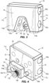
- FIGS. 3 and 4 illustrate the bit holder 42.
- the bit holder 42 is configured to retain at least one tool bit B for transport therewith along with the power tool 10.
- the bit holder 42 is mountable to the power tool 10 ( FIG. 1 ).
- the bit holder 42 may be selectively mounted to either the first (i.e., right) side 48a or the second (i.e., left) side 48b of the power tool 10.
- the bit holder 42 may be described as being reversible. As illustrated in FIG.
- the bit holder 42 includes a frame 50 and a bit holding portion 54.
- An adapter 58 is selectively coupled to the bit holder 42.
- the adapter 58 includes a coupling plate 62.
- the bit holding portion 54 is mounted to a first face 66 of the frame 50.
- the adapter 58 is mounted to a second face 70 of the frame 50.
- the coupling plate 62 and the adapter 58 are formed as two separate components which are integrally coupled to one another in the illustrated embodiment. Other embodiments where the adapter 58 and coupling plate 62 are formed as a single component or more than two components are possible.
- the bit holder 42 additionally includes a first end 71a and an opposite second end 71b.
- FIG. 1A illustrates the bit holder 42 removed from the power tool 10.
- the power tool 10 may receive the bit holder 42 at a mounting structure 72 located on the power tool 10.
- the power tool 10 includes two mounting structures 72, each mounting structure 72 being located on one of the first side 48a and the second side 48b of the power tool 10. Only the mounting structure 72 adjacent the first side 48a is visible in FIG. 1A .
- the power tool 10 may include more than two mounting structures 72.
- a mounting structure 72 may be located on any of the sides 48a-48f of the power tool 10.
- the bit holder 42 interfaces with the adapter 58 to couple the bit holder 42 to the mounting structure 72.
- the frame 50 of the bit holder 42 may interface directly with a mounting structure 72 on the power tool 10.
- the bit holder 42 is compatible to couple with each of the mounting structures 72 on the first side 48a and the second side 48b of the power tool 10.
- the adapter 58 is positioned between the bit holding portion 54 of the bit holder 42 and the power tool 10 on the first side 48a of the power tool 10.
- the first end 71a of the bit holder 42 generally faces the third side 48c of the power tool 10
- the second end 71b of the bit holder 42 generally faces the fourth side 48d of the power tool 10.
- the bit holder 42 may be removed from the mounting structure 72 on the first side 48a.
- the bit holder 42 is then moved to the second side 48b of the power tool 10 and flipped about the longitudinal axis LA of the power tool 10 such that the adapter 58 is positioned between the bit holding portion 54 and the power tool 10 on the second side 48b of the power tool 10.
- the second end 71b of the bit holder 42 generally faces the third side 48c of the power tool 10 and the first end 71a of the bit holder 42 generally faces the fourth side 48d of the power tool 10.
- bit holder 42 may then be mounted to the mounting structure 72 on the second side 48b of the power tool 10, as will be described in further detail.
- FIG. 1C illustrates a first tool 10a, the first tool 10a being substantially the same as the power tool 10 (e.g., the drill) illustrated in FIG. 1 , and a second tool 10b (e.g., an impact driver or the like), and the bit holder 42.
- the first tool 10a includes a first mounting structure 72a that is compatible with the adapter 58.
- the second tool 10b includes a second mounting structure 72b that is compatible with the frame 50 of the bit holder 42.
- the bit holder 42 is interfaced with the adapter 58 such that the adapter 58 is positioned between the bit holding portion 54 and the first mounting structure 72a.
- the frame 50 of the bit holder 42 directly engages the second mounting structure 72b (i.e., without the adapter 58).
- the frame 50 is formed of a generally rigid polymer.
- the first face 66 of the frame 50 includes lower mounting brackets 78, upper mounting brackets 82, a central tab bracket 86, a plurality of through holes 90, a fastener receiving hole 94, an arced groove 98, and a recessed outer periphery 102.
- the second face 70 of the frame 50 includes a plurality of mounting protrusions 106a, 106b projecting therefrom. With reference to FIGS. 5 and 6 , each of the plurality of through holes 90 and the fastener receiving hole 94 extend from the first face 66 through the second face 70.
- the first face 66 of the frame 50 includes two lower mounting brackets 78 and two upper mounting brackets 82.
- the lower mounting brackets 78 are tabs projecting from the first face 66.
- the upper mounting brackets 82 are generally thicker than the lower mounting brackets 78 and include a plurality of channels 110 defined therein.
- the central tab bracket 86 is located between the two upper mounting brackets 82.
- the frame 50 includes six through holes 90. Each of the through holes 90 has a smaller diameter D 1 ( FIG. 5 ) at an opening on the first face 66 of the frame 74 than a diameter D2 ( FIG. 6 ) at an opening on the second face 70 of the frame 50.
- the fastener receiving hole 94 is positioned between the lower mounting brackets 78.
- an arch-shaped cavity 122 of the bit holding portion 54 is aligned with the fastener receiving hole 94 of the frame 50.
- This arrangement permits user access to the fastener 178 in the fastener receiving hole 94 through the arch-shaped cavity 122.
- the fastener receiving hole 94 has a larger diameter D3 at an opening on the first face 66 of the frame 50 than a diameter D4 at an opening on the second face 70 of the frame 50.
- the plurality of mounting protrusions 106a, 106b positioned on the second face 70 of the frame 50 includes a first mounting protrusion 106a and a second mounting protrusion 106b.
- the first mounting protrusion 106a and the second mounting protrusion 106b are positioned on opposite sides of the fastener receiving hole 94 from each other.
- Each of the first mounting protrusion 106a and the second mounting protrusion 106b have a diameter D5.
- the bit holding portion 54 is molded over the first face 66 of the frame 50 ( FIG. 5 ).
- the bit holding portion 54 has two leg portions 118a, 118b (i.e., a first side and a second side) and an extending portion 120 (i.e., a span) extending between the leg portions 118a, 118b.
- the leg portions 118a, 118b, and the extending portion 120 in combination, define an arch-shaped cavity 122 in the bit holding portion 54.
- the cavity 122 is bounded by the leg portions 118a, 118b and the extending portion 120.
- the bit holding portion 54 is generally arch-shaped.
- the bit holding portion 54 is formed of an elastomeric material.
- the elastomeric material enables the bit holding portion 54 to flex relative to the frame 50 ( FIG. 5 ).
- the bit holding portion 54 further includes lower mounting apertures 126, upper mounting apertures 130, a central mounting aperture 134, a plurality of molded protrusions 138, an arced protrusion 142, a protruding outer periphery 146, and a plurality of bit retaining apertures 150a, 150b.
- the bit holding portion 54 includes two lower mounting apertures 126 that are molded around the two lower mounting brackets 78 ( FIG. 5 ) of the frame 50 and two upper mounting apertures 130 that are molded around the two upper mounting brackets 82 ( FIG. 5 ) of the frame 50.
- the central mounting aperture 134 is molded around the central tab bracket 86 ( FIG. 5 ).
- Each of the plurality of molded protrusions 138 is molded to fill a corresponding one of the plurality through holes 90 ( FIG. 5 ).
- each of the plurality of molded protrusions 138 includes a relatively small diameter portion 138a having a diameter corresponding to the diameter (i.e., first diameter) D1 and molded into one of the through holes 90 of the frame 50 ( FIG. 5 ).
- Each of the plurality of molded protrusions 138 further includes a relatively large diameter portion 138b having a diameter corresponding to the diameter D2 (i.e., second diameter).
- the diameter D2 is nominally greater than the diameter D1 of the through holes 90.
- the large diameter portion 138b is molded into the opening in the second face 70 of the frame 50 ( FIG. 6 ).
- the arced protrusion 142 is formed generally adjacent to the arch-shaped cavity 122.
- the arced protrusion 142 is molded into the arced groove 98 of the frame 50 ( FIG. 6 ).
- the protruding outer periphery 146 is formed over the recessed outer periphery 102 of the frame 50 ( FIG. 6 ).
- each of the lower mounting apertures 126, the upper mounting apertures 130, the central mounting aperture 134, the plurality of molded protrusions 138, the arced protrusion 142, and the protruding outer periphery 146 is moldedly formed over or in a corresponding feature on the frame 50 ( FIG. 6 ) to couple the bit holding portion 54 to the frame 50.
- the bit holding portion 54 of the illustrated embodiment includes two bit retaining apertures 150a, 150b.
- Each of the bit retaining apertures 150a, 150b is formed through the bit holding portion 54.
- Each of the bit retaining apertures 150a, 150b extends along a direction that is perpendicular to an extension direction of the plurality of molded protrusions 138.
- Each of the bit retaining apertures 150a, 150b is configured to receive the bit B therein to couple the bit B to the power tool 10.
- a first bit retaining aperture 150a is positioned generally adjacent the lower mounting apertures 126 and extends through each of the leg portions 118a, 118b of the bit holding portion 54.
- a second bit retaining aperture 150b is positioned opposite the first bit retaining aperture 150a such that the upper mounting apertures 130 are positioned generally between the first bit retaining aperture 150a and the second bit retaining aperture 150b.
- Each of the first bit retaining aperture 150a and the second bit retaining aperture 150b is configured to retain a tool bit B as will be described in further detail below.
- the bit retaining apertures 150a, 150b may extend from the first end 71a of the bit holder 42 to the second end 71b of the bit holder 42.
- the bit retaining apertures 150a, 150b may be in communication with the first end 71a and the second end 71b of the bit holding portion 54.
- the bit retaining aperture 150a is in communication with the arch-shaped cavity 122. Accordingly, a user may be permitted access to the bit B through the arch-shaped cavity 122 to eject the bit B from the bit retaining aperture 150a.
- the bit retaining aperture 150a is also divided into two discrete section such that relatively short tool bits do not become lost in the aperture 150a. Rather, with a relatively short tool bit, one end of the bit will always protrude from an end of one of the discrete sections of the bit retaining aperture 150a.
- the frame 50 and the bit holding portion 54 are formed of different materials.
- the frame 50 is formed of a generally rigid polymer such as, for example, PVC.
- the bit holding portion 54 is formed of a generally elastomeric material, such as, for example, rubber.
- the frame 50 may be formed other materials such as nylon, glass nylon, or other similar plastics.
- the frame 50 may be formed of a metal, such as steel, a ceramic, or any other suitable material.
- FIGS. 9 and 10 illustrate the adapter 58 and the coupling plate 62.
- the adapter 58 includes a first end 58a and a second end 58b.
- the adapter 58 defines a first aperture 154, a second aperture 158, and an end slot 162.
- the first aperture 154 is positioned adjacent the first end 58a.
- the end slot 162 is positioned adjacent the second end 58b.
- the second aperture 158 is positioned between the end slot 162 and the first aperture 154.
- the coupling plate 62 includes a tab 166.
- the coupling plate 62 defines a first coupling plate aperture 170 and a second coupling plate aperture 174.
- the tab 166 protrudes from the end slot 162 of the adapter 58.
- the first coupling plate aperture 170 is positioned concentrically with the first aperture 154 of the adapter 58.
- the second coupling plate aperture 174 is positioned concentrically with the second aperture 158 of the adapter 58.
- the first aperture 154 of the adapter 58 and the first coupling plate aperture 170 are positioned concentrically with the fastener receiving hole 94 of the frame 50.
- the first aperture 154 of the adapter 58 and the first coupling plate aperture 170 are configured to receive the fastener 178 ( FIG. 11 ).
- the diameter D4 of each of the first aperture 154 and the first coupling plate aperture 170 is substantially equivalent to the diameter D4 at the opening in the second face 70 of the frame 50 ( FIG. 6 ).
- the second aperture 158 of the adapter 58 and the second coupling plate aperture 174 are configured to receive, or mount to, one of the first mounting protrusion 106a and the second mounting protrusion 106b.
- the diameter D5 of each of the second aperture 158 and the second coupling plate aperture 174 is substantially equivalent to the diameter D5 of the mounting protrusions 106a, 106b such that the mounting protrusions 106a, 106b may snap fit to each of the second aperture 158 and the second coupling plate aperture 174.
- the power tool 10 further includes the mounting structures 72 for receiving and coupling with the bit holder 42 ( FIG. 3 ).
- Each mounting structure 72 includes an aperture 182 that receives the fastener 178, and a fastener receiving bushing 186 ( FIG. 4 ) located in the aperture 182 configured to engage the fastener 178 to secure the bit holder 42 to the power tool 10.
- the fastener receiving bushing 186 is coupled to the power tool 10.
- the mounting structures 72a of the first tool 10a include a receiving slot 190.
- the receiving slot 190 is positioned between the fastener 178 and the output end 46 ( FIG. 1 ) of the power tool 10.
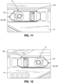
- the power tool 10 includes a right-side mounting structure 72, illustrated in FIG.
- bit holder 42 is reversible such that the bit holder 42 may be coupled to either of the right-side mounting structure 72 or the left-side mounting structure 72.
- the adapter 58 of the bit holder 42 may be mounted to the frame 50 such that the second aperture 158 of the adapter 58 and the second coupling plate aperture 174 receive the first mounting protrusion 106a of the frame 50 ( FIG. 6 ).
- the tab 166 of the coupling plate 62 is positioned adjacent the first side 71a of the bit holder 42.
- the fastener 178 may then be unfastened from the right-side mounting structure 72.
- the fastener 178 may be a screw such that the fastener 178 is unscrewed from the right-side mounting structure 72.
- the bit holder 42 may be placed into alignment with the right-side mounting structure 72a such that the tab 166 of the coupling plate 62 extends into the receiving slot 190.
- the fastener receiving hole 94 of the frame 50, the first aperture 154 of the adapter 58 ( FIG. 10 ), and the first coupling plate aperture 170 ( FIG. 10 ) are each concentrically aligned with the fastener receiving bushing 186.
- the fastener 178 may then be re-inserted for engagement with the fastener receiving bushing 186 through the fastener receiving hole 94 of the frame 50, the first aperture 154 of the adapter 58 ( FIG. 10 ), and the first coupling plate aperture 170 ( FIG. 10 ) to couple the bit holder 42 to the power tool 10.
- the bit holder 42 may be coupled to the left-side mounting structure 72 in a manner substantially similar as the right-side mounting structure 72 ( FIG. 11 ), but with the adapter 58 engaging the mounting protrusion 180b of the frame 50.
- the tab 166 of the coupling plate 62 is positioned at the second side 71b of the bit holder 42, rather than the first side 71a.
- the bit holder 42 may be coupled to each of the first side 48a and the second side 48b of the power tool 10 without requiring additional components.
- the bit holder 42 is effectively formed as a reversible bit holder 42.
- inactive tool bits B may be inserted into the first bit retaining aperture 150a and the second bit retaining aperture 150b.
- the elastomeric material of the bit holding portion 54 of the bit holding portion 54 provides friction so that inserted tool bits are inhibited from loosening from the bit holder 42.
- the first bit retaining aperture 150a may advantageously receive relatively small tool bits individually in one of the two leg portions 118a, 118b.
- leg portions 118a, 118b having the first bit retaining aperture 150a in communication with the arch-shaped cavity 122 thus provide improved access to the bits B received in the first bit retaining aperture 150a. This effectively reduces the difficulty in removing relatively small tool bits B from the bit holder 42.
- FIG. 13 illustrates the power tool 10b of FIG. 1C in detail.
- the power tool 10b is substantially similar to the power tool 10a except for the differences described herein.
- the power tool 10b includes a first side 204a, a second side 204b, a third side 204c, a fourth side 204d, a fifth side 204e, and a sixth side 204f defined in generally the same orientation as the power tool 10.
- the power tool 10b further includes a handle portion 208, a motor housing portion 212, and a battery receptacle 216.
- the motor housing portion 212 extends generally along the longitudinal axis LA between the third side 204c and the fourth side 204d.
- the handle portion 208 extends from the motor housing portion 212 generally from the fifth side 204e to the sixth side 204f.
- the handle portion 208 includes a proximal end 220 and a distal end 224.
- the proximal end 220 is located adjacent the motor housing portion 212.
- the distal end 224 is located opposite the proximal end 220 and adjacent the sixth side 204f of the power tool 10b.
- the battery receptacle 216 is positioned at the distal end 224 of the handle portion 218.
- the power tool 10b includes a mounting structure 72b, that is the second mounting structure 72b of FIG. 1C , positioned on the battery receptacle 216 at the distal end 224 of the handle portion 208. More specifically, the power tool 10b includes two mounting structures 72b. One mounting structure 72b is located on the first side 204a, and the other mounting structure 72b is located on the second side 204b opposite the first side 204a. Other positions, orientations, and numbers of mounting structures 72b on the power tool 10b are possible. Each mounting structure 72b is positioned adjacent the battery receptacle 216. The mounting structure 72b is configured to receive the bit holder 42.
- the mounting structure 72b includes two protrusion receiving apertures 228a, 228b, a fastener receiving aperture 230, and a fastener 232 received in the fastener receiving aperture 230.
- the protrusion receiving apertures 228a, 228b have substantially the same diameter D5 as the mounting protrusions 106a, 106b of FIG. 4 .
- the mounting protrusions 106a, 106b of FIG. 4 may be snap fit into the protrusion receiving apertures 228a, 228b such that the frame 50 of the bit holder 42 directly engages the mounting structure 72b.
- the bit holder 42 is reversible between the mounting structures 72b on each of the first side 204a and the second side 204b of the power tool 10b as similarly described with respect to FIG. 1B .
- the tab 166 and the fastener 178 function as mounting elements to engage the mounting structure 72a of the power tool 10 and to secure the bit holder 42 to the power tool 10a.
- the mounting protrusions 106a, 106b and the fastener 232 function as mounting elements to engage the mounting structure 72b of the power tool 10b and to secure the bit holder 42 to the power tool 10b.
- the fastener 178 is dimensioned to selectively couple the bit holder 42 to the power tool 10b.
- the fastener 232 is dimensioned to selectively couple the bit holder 42 and the adapter 58 to the power tool 10a with the adapter 58 sandwiched between the bit holder 42 and the power too l10a.
- the fastener 178 and the fastener 232 differ in length. More specifically, the fastener 178 is longer than the fastener 232, at least to account for the thickness of the adapter 58.
- bits B are configured to engage the bit retaining apertures 150a, 150b to be secured to the corresponding power tool 10a, 10b.
- the power tool 10 may utilize the mounting structures 72 described herein to mount other articles to the power tool 10.
- a belt clip 300 may be selectively mounted to the mounting structures 72.
- the belt clip 300 may be removed from the mounting structure 72 to accommodate the bit holder 42 or another article for coupling engagement with the power tool 10.
Landscapes
- Engineering & Computer Science (AREA)
- Mechanical Engineering (AREA)
- Details Of Spanners, Wrenches, And Screw Drivers And Accessories (AREA)
- Portable Nailing Machines And Staplers (AREA)
Abstract
Description
- This application claims priority to co-pending
U.S. Provisional Patent Application No. 63/340,559, filed May 11, 2022 - The present disclosure relates to accessories for power tools, and more specifically, to bit holders for use with power tools.
- Some power tools such as drills are configured to be selectively connected with tool bits. Typically, tool bits not in use with the power tool are stored at a remote location. Typically, one tool bit is attached to a chuck prior to operation of the power tool. Depending on use of the power tool, different tool bits may be secured to the chuck.
- The invention provides, in one aspect, a bit holder configured to engage a power tool. The bit holder comprises a mounting element configured to alternately engage a first mounting structure on a first side of the power tool and a second mounting structure on a second side of the power tool. The bit holder further comprises a bit holding portion including a bit retaining aperture configured to at least partially receive a bit to secure the bit to the power tool.
- The invention provides, in another aspect, a bit holder assembly for use with a first power tool having a first mounting structure and a second power tool having a second mounting structure that is different than the first mounting structure. The bit holder assembly comprises a bit holder and an adapter. The bit holder includes a holder mounting element and a bit holding portion including a bit retaining aperture configured to at least partially receive a bit. The adapter includes an adapter mounting element and an aperture. The bit holder is configured to be removably coupled to the first power tool with the holder mounting element in engagement with the first mounting structure. The bit holder is configured to be removably coupled to the second power tool with the holder mounting element in engagement with the aperture and the adapter mounting element in engagement with the second mounting structure.
- The invention provides, in another aspect, a bit holder configured to engage a power tool. The bit holder comprises a mounting element and a bit holding portion. The mounting element is configured to removably engage a mounting structure of the power tool. The bit holding portion has a first side, a second side opposite the first side, and a span extending between the first side and the second side to form an arch. The bit holding portion defines a cavity bounded by the first side, the second side, and the span. The bit holding portion also defines a bit retaining aperture in communication with the cavity and configured to at least partially receive a bit to secure the bit to the power tool.
- According to another aspect, we provide a bit holder configured to engage a power tool, the bit holder comprising:
- a mounting element configured to alternately engage a first mounting structure on a first side of the power tool and a second mounting structure on a second side of the power tool; and
- a bit holding portion including a bit retaining aperture configured to at least partially receive a bit to secure the bit to the power tool.
- The second side may be opposite the first side.
- The bit holding portion may be arch-shaped and may include two leg portions and an extending portion extending between the leg portions to define a cavity in the bit holding portion.
- The bit retaining aperture may be in communication with the cavity.
- The bit retaining aperture may be in communication with a first end and a second end that may be opposite the first end of the bit holding portion.
- The mounting element may include a fastener that may be alternately received in an aperture of the first mounting structure and an aperture of the second mounting structure.
- The bit holder may further comprise a frame secured to the bit holding portion, wherein the frame may include a fastener receiving hole configured to receive the mounting element.
- The bit holding portion may include a cavity, and wherein the frame may be secured to the bit holding portion with the fastener receiving hole of the frame aligned with the cavity of the bit holding potion.
- The frame may be made of a first material and the bit holding portion may be made of an elastomeric material different than the first material.
- The bit holding portion may be molded onto the frame, the frame may include a plurality of through holes, and the bit holding portion may include a plurality of molded protrusions which engage the through holes of the frame.
- The mounting element may include a mounting protrusion that alternately engages a protrusion receiving aperture of the first mounting structure and a protrusion receiving aperture of the second mounting structure by snap fit.
- The mounting element may also include a second mounting protrusion that alternately engages a second protrusion receiving aperture of the first mounting structure and a second protrusion receiving aperture of the second mounting structure by snap fit.
- The bit holder may further comprise a fastener configured to alternately engage a fastener receiving aperture of the first mounting structure and a fastener receiving aperture of the second mounting structure.
- The bit retaining aperture may be a first bit retaining aperture, and wherein the bit holding portion may include a second bit retaining aperture configured to at least partially receive a second bit to secure the second bit to the power tool.
- The bit retaining aperture may be also configured to at least partially receive a second bit to secure the second bit to the power tool.
- According to another aspect we provide a bit holder assembly for use with a first power tool and a second power tool, the first power tool having a first mounting structure, the second power tool having a second mounting structure that is different than the first mounting structure, the bit holder assembly comprising:
- a bit holder including a holder mounting element and a bit holding portion including a bit retaining aperture configured to receive at least partially receive a bit; and
- an adapter including an adapter mounting element and an aperture,
- wherein the bit holder is configured to be removably coupled to the first power tool with the holder mounting element in engagement with the first mounting structure, and
- wherein the bit holder is configured to be removably coupled to the second power tool with the holder mounting element in engagement with the aperture and the adapter mounting element in engagement with the second mounting structure.
- The adapter mounting element may include a tab configured to engage a receiving slot of the second mounting structure.
- The bit holder may be configured to be removably coupled to any one of a first side of the first power tool, a second side of the first power tool, a first side of the second power tool, and a second side of the second power tool, the first side and the second side of the first power tool may be opposing one another, and the first side and the second side of the second side of the second power tool may be opposing one another.
- The bit holder assembly may further comprise a first fastener configured to selectively removably couple the bit holder with the first power tool and a second fastener configured to selectively removably couple the bit holder with the second power tool with the adapter sandwiched between the bit holder and the second power tool, wherein the first fastener and the second fastener differ in length.
- According to another aspect we provide a bit holder configured to engage a power tool, the bit holder comprising:
- a mounting element configured to removably engage a mounting structure of the power tool; and
- a bit holding portion having a first side, a second side opposite the first side, and a span extending between the first side and the second side to form an arch, the bit holding portion defining a cavity bounded by the first side, the second side, and the span, the bit holding portion also defining a bit retaining aperture in communication with the cavity and configured to at least partially receive a bit to secure the bit to the power tool.
- The bit retaining aperture may extend through first side, and wherein the bit retaining aperture may be in communication with the cavity and a first end of the bit holder.
- The bit retaining aperture may also extend through the second side, and wherein the bit retaining aperture may be in communication with the cavity and a second end of the bit holder opposite the first end of the bit holder.
- The bit holder may further comprise a second bit retaining aperture positioned in the span, wherein the second bit retaining aperture may be in communication with the first side and the second side.
- Other aspects of the invention will become apparent by consideration of the following detailed description and accompanying drawings.
-
-
FIG. 1 is perspective view of a power tool and bit holder according to an embodiment of the disclosure. -
FIG. 1A is an exploded view of the power tool and bit holder ofFIG. 1 along with an adapter. -
FIG. 1B is a schematic view of the power tool and bit holder ofFIG. 1 . -
FIG. 1C is a schematic view of the power tool and bit holder ofFIG. 1 along with a second power tool. -
FIG. 2 is a cross-sectional view of the power tool ofFIG. 1 taken along section line 2-2 inFIG. 1 . -
FIG. 3 is a front perspective view of the bit holder ofFIG. 1 . -
FIG. 4 is a rear perspective view of the bit holder and the adapter ofFIG. 1A along with a fastener receiving bushing. -
FIG. 5 is a front perspective view of a frame of the bit holder ofFIG. 3 . -
FIG. 6 is a rear perspective view of the frame ofFIG. 5 . -
FIG. 7 is a front perspective view of a bit holding portion for the bit holder ofFIG. 3 . -
FIG. 8 is a rear perspective view of the bit holding portion ofFIG. 7 . -
FIG. 9 is a front view of the adapter ofFIG. 1A . -
FIG. 10 is an exploded view of the adapter ofFIG. 9 . -
FIG. 11 is a first side view of a mounting structure for the power tool ofFIG. 1 . -
FIG. 12 is a second side view of the mounting structure for the power tool ofFIG. 1 . -
FIG. 13 is a perspective view of the second power tool ofFIG. 1C . -
FIG. 14 is an exploded view of the second power tool and the bit holder ofFIG. 1C . -
FIG. 15 is a side view of a mounting structure of the second power tool ofFIG. 13 . - Before any embodiments of the invention are explained in detail, it is to be understood that the invention is not limited in its application to the details of construction and the arrangement of components set forth in the following description or illustrated in the following drawings. Also, it is to be understood that the phraseology and terminology used herein is for the purpose of description and should not be regarded as limiting. The invention is capable of other embodiments and of being practiced or of being carried out in various ways.
-
FIGS. 1 and2 illustrate apower tool 10 in the form of a rotary tool, and, more specifically, a drill. Thepower tool 10 includes ahousing 14 having ahandle portion 18, amotor housing 22, and abattery receptacle 30 configured to receive a battery pack. In the illustrated embodiment, thebattery receptacle 30 is located at a bottom end or foot of thehandle portion 18 opposite themotor housing 22. Thepower tool 10 further includes a motor 34 (FIG. 2 ) supported in themotor housing 22 and atransmission 38 driven by themotor 34. As will be described in detail below, a bit holder 42 (i.e., an accessory) is configured to be attached to thepower tool 10. Thebit holder 42 is configured to secure tool bits B for use with thepower tool 10 thereto. Various types ofpower tools 10 may be configured to engage thebit holder 42 with similar attachment mechanisms as described herein. - The
battery receptacle 30 may be configured to engage and receive power from, for example, a 12 volt battery pack, an 18 volt battery pack, a 28 volt battery pack, a 40 volt battery pack, or a battery pack of any other voltage suitable for powering thepower tool 10. In alternate embodiments, thepower tool 10 may be powered by an external power source providing an AC current. Themotor 34 receives power from the battery 26 to drive thetransmission 38. Thetransmission 38 includes anoutput end 46 for transmitting torque to a workpiece. In the illustrated embodiment, theoutput end 46 may be configured as a chuck configured to receive torque from thetransmission 38 and transmit torque to a tool such as a cutting bit B. In other embodiments, theoutput end 46 may transmit torque or other forces to another working bit. For example, and without limitation, the another working bit may be a fastening bit such as a screw driving bit or a socket bit configured to tighten or loosen a workpiece. The bit B may be decoupled to theoutput end 46 and coupled to thebit holder 42 for storage thereof. Optionally, thepower tool 10 may be transported to another location with the bit secured to thebit holder 42. Accordingly, access to a plurality of bits, either coupled to thebit holder 42 or theoutput end 46 is permitted. - The
power tool 10 includes a plurality ofsides 48a-48f. Specifically, the power tool includes afirst side 48a, asecond side 48b, athird side 48c, afourth side 48d, afifth side 48e, and asixth side 48f. Thefirst side 48a is a right side of thepower tool 10. Thesecond side 48b is a left side of thepower tool 10. Thethird side 48c is a front side of thepower tool 10. Thefourth side 48d is a rear side of thepower tool 10. Thefifth side 48e is a top side of thepower tool 10. Thesixth side 48f is a bottom side of thepower tool 10. Themotor housing 22 extends along the longitudinal axis LA between thethird side 48c and thefourth side 48d. Thehandle portion 18 extends from themotor housing 22 generally from thefifth side 48e to thesixth side 48f. Thepower tool 10 generally extends along a longitudinal axis LA (FIG. 1B ) between thethird side 48c and thefourth side 48c. As shown inFIG. 2 , themotor 34,transmission 38, andoutput end 46 in the illustratedpower tool 10 are generally aligned along the longitudinal axis LA. Other configurations are possible. Thefirst side 48a extends between thethird side 48c and thefourth side 48d. Thesecond side 48b extends between thethird side 48c and thefourth side 48d opposite the longitudinal axis L from thefirst side 48a. -
FIGS. 3 and 4 illustrate thebit holder 42. Thebit holder 42 is configured to retain at least one tool bit B for transport therewith along with thepower tool 10. Thebit holder 42 is mountable to the power tool 10 (FIG. 1 ). As best illustrated inFIG. 1B , thebit holder 42 may be selectively mounted to either the first (i.e., right)side 48a or the second (i.e., left)side 48b of thepower tool 10. As thebit holder 42 may be mounted to either the first (i.e., right)side 48a or the second (i.e., left) side of thepower tool 10, thebit holder 42 may be described as being reversible. As illustrated inFIG. 4 , thebit holder 42 includes aframe 50 and abit holding portion 54. Anadapter 58 is selectively coupled to thebit holder 42. Theadapter 58 includes acoupling plate 62. Thebit holding portion 54 is mounted to afirst face 66 of theframe 50. Theadapter 58 is mounted to asecond face 70 of theframe 50. Thecoupling plate 62 and theadapter 58 are formed as two separate components which are integrally coupled to one another in the illustrated embodiment. Other embodiments where theadapter 58 andcoupling plate 62 are formed as a single component or more than two components are possible. Thebit holder 42 additionally includes afirst end 71a and an oppositesecond end 71b. -
FIG. 1A illustrates thebit holder 42 removed from thepower tool 10. Thepower tool 10 may receive thebit holder 42 at a mountingstructure 72 located on thepower tool 10. In the illustrated embodiment, thepower tool 10 includes two mountingstructures 72, each mountingstructure 72 being located on one of thefirst side 48a and thesecond side 48b of thepower tool 10. Only the mountingstructure 72 adjacent thefirst side 48a is visible inFIG. 1A . In other embodiments, thepower tool 10 may include more than two mountingstructures 72. A mountingstructure 72 may be located on any of thesides 48a-48f of thepower tool 10. As illustrated inFIG. 1A , thebit holder 42 interfaces with theadapter 58 to couple thebit holder 42 to the mountingstructure 72. In other embodiments, such as the embodiment ofFIG. 14 described below, theframe 50 of thebit holder 42 may interface directly with a mountingstructure 72 on thepower tool 10. - As illustrated in
FIG. 1B , thebit holder 42 is compatible to couple with each of the mountingstructures 72 on thefirst side 48a and thesecond side 48b of thepower tool 10. For example, when thebit holder 42 is coupled to the mountingstructure 72 on thefirst side 48a, theadapter 58 is positioned between thebit holding portion 54 of thebit holder 42 and thepower tool 10 on thefirst side 48a of thepower tool 10. In this position, thefirst end 71a of thebit holder 42 generally faces thethird side 48c of thepower tool 10 and thesecond end 71b of thebit holder 42 generally faces thefourth side 48d of thepower tool 10. To couple thebit holder 42 to the mountingstructure 72 on thesecond side 48b of thepower tool 10, thebit holder 42 may be removed from the mountingstructure 72 on thefirst side 48a. Thebit holder 42 is then moved to thesecond side 48b of thepower tool 10 and flipped about the longitudinal axis LA of thepower tool 10 such that theadapter 58 is positioned between thebit holding portion 54 and thepower tool 10 on thesecond side 48b of thepower tool 10. Once attached to thepower tool 10, thesecond end 71b of thebit holder 42 generally faces thethird side 48c of thepower tool 10 and thefirst end 71a of thebit holder 42 generally faces thefourth side 48d of thepower tool 10. In other words, once thebit holder 42 is attached to the opposing first orsecond side end bit holder 42 faces an opposing third orfourth side power tool 10. Thebit holder 42 may then be mounted to the mountingstructure 72 on thesecond side 48b of thepower tool 10, as will be described in further detail. -
FIG. 1C illustrates afirst tool 10a, thefirst tool 10a being substantially the same as the power tool 10 (e.g., the drill) illustrated inFIG. 1 , and asecond tool 10b (e.g., an impact driver or the like), and thebit holder 42. Thefirst tool 10a includes afirst mounting structure 72a that is compatible with theadapter 58. Thesecond tool 10b includes asecond mounting structure 72b that is compatible with theframe 50 of thebit holder 42. To couple thebit holder 42 to thefirst tool 10a, thebit holder 42 is interfaced with theadapter 58 such that theadapter 58 is positioned between thebit holding portion 54 and thefirst mounting structure 72a. To couple thebit holder 42 to thesecond tool 10b, theframe 50 of thebit holder 42 directly engages thesecond mounting structure 72b (i.e., without the adapter 58). - As illustrated in
FIG. 5 , in the illustrated embodiment, theframe 50 is formed of a generally rigid polymer. Thefirst face 66 of theframe 50 includes lower mountingbrackets 78, upper mountingbrackets 82, acentral tab bracket 86, a plurality of throughholes 90, afastener receiving hole 94, an arcedgroove 98, and a recessedouter periphery 102. As best illustrated inFIG. 6 , thesecond face 70 of theframe 50 includes a plurality of mountingprotrusions FIGS. 5 and 6 , each of the plurality of throughholes 90 and thefastener receiving hole 94 extend from thefirst face 66 through thesecond face 70. Thefirst face 66 of theframe 50 includes twolower mounting brackets 78 and two upper mountingbrackets 82. Thelower mounting brackets 78 are tabs projecting from thefirst face 66. The upper mountingbrackets 82 are generally thicker than the lower mountingbrackets 78 and include a plurality ofchannels 110 defined therein. Thecentral tab bracket 86 is located between the two upper mountingbrackets 82. Theframe 50 includes six throughholes 90. Each of the throughholes 90 has a smaller diameter D 1 (FIG. 5 ) at an opening on thefirst face 66 of the frame 74 than a diameter D2 (FIG. 6 ) at an opening on thesecond face 70 of theframe 50. Thefastener receiving hole 94 is positioned between the lower mountingbrackets 78. When theframe 50 andbit holding portion 54 are secured to one another (FIG. 3 ), an arch-shapedcavity 122 of thebit holding portion 54 is aligned with thefastener receiving hole 94 of theframe 50. This arrangement permits user access to thefastener 178 in thefastener receiving hole 94 through the arch-shapedcavity 122. Thefastener receiving hole 94 has a larger diameter D3 at an opening on thefirst face 66 of theframe 50 than a diameter D4 at an opening on thesecond face 70 of theframe 50. In the illustrated embodiment, the plurality of mountingprotrusions second face 70 of theframe 50 includes afirst mounting protrusion 106a and asecond mounting protrusion 106b. Thefirst mounting protrusion 106a and the second mountingprotrusion 106b are positioned on opposite sides of thefastener receiving hole 94 from each other. Each of the first mountingprotrusion 106a and the second mountingprotrusion 106b have a diameter D5. - Now referring to
FIGS. 7 and 8 , thebit holding portion 54 is molded over thefirst face 66 of the frame 50 (FIG. 5 ). Thebit holding portion 54 has twoleg portions leg portions leg portions portion 120, in combination, define an arch-shapedcavity 122 in thebit holding portion 54. Thecavity 122 is bounded by theleg portions portion 120. As such, thebit holding portion 54 is generally arch-shaped. In the illustrated embodiment, thebit holding portion 54 is formed of an elastomeric material. The elastomeric material enables thebit holding portion 54 to flex relative to the frame 50 (FIG. 5 ). Thebit holding portion 54 further includes lower mountingapertures 126, upper mountingapertures 130, acentral mounting aperture 134, a plurality of moldedprotrusions 138, an arcedprotrusion 142, a protrudingouter periphery 146, and a plurality ofbit retaining apertures - In the illustrated embodiment, the
bit holding portion 54 includes two lower mountingapertures 126 that are molded around the two lower mounting brackets 78 (FIG. 5 ) of theframe 50 and two upper mountingapertures 130 that are molded around the two upper mounting brackets 82 (FIG. 5 ) of theframe 50. Thecentral mounting aperture 134 is molded around the central tab bracket 86 (FIG. 5 ). Each of the plurality of moldedprotrusions 138 is molded to fill a corresponding one of the plurality through holes 90 (FIG. 5 ). Specifically, each of the plurality of moldedprotrusions 138 includes a relativelysmall diameter portion 138a having a diameter corresponding to the diameter (i.e., first diameter) D1 and molded into one of the throughholes 90 of the frame 50 (FIG. 5 ). Each of the plurality of moldedprotrusions 138 further includes a relativelylarge diameter portion 138b having a diameter corresponding to the diameter D2 (i.e., second diameter). The diameter D2 is nominally greater than the diameter D1 of the through holes 90. Thelarge diameter portion 138b is molded into the opening in thesecond face 70 of the frame 50 (FIG. 6 ). The arcedprotrusion 142 is formed generally adjacent to the arch-shapedcavity 122. The arcedprotrusion 142 is molded into the arcedgroove 98 of the frame 50 (FIG. 6 ). The protrudingouter periphery 146 is formed over the recessedouter periphery 102 of the frame 50 (FIG. 6 ). As such, each of the lower mountingapertures 126, the upper mountingapertures 130, thecentral mounting aperture 134, the plurality of moldedprotrusions 138, the arcedprotrusion 142, and the protrudingouter periphery 146 is moldedly formed over or in a corresponding feature on the frame 50 (FIG. 6 ) to couple thebit holding portion 54 to theframe 50. - With continued reference to
FIGS. 7 and 8 , thebit holding portion 54 of the illustrated embodiment includes twobit retaining apertures bit retaining apertures bit holding portion 54. Each of thebit retaining apertures protrusions 138. Each of thebit retaining apertures power tool 10. A firstbit retaining aperture 150a is positioned generally adjacent the lower mountingapertures 126 and extends through each of theleg portions bit holding portion 54. A secondbit retaining aperture 150b is positioned opposite the firstbit retaining aperture 150a such that the upper mountingapertures 130 are positioned generally between the firstbit retaining aperture 150a and the secondbit retaining aperture 150b. Each of the firstbit retaining aperture 150a and the secondbit retaining aperture 150b is configured to retain a tool bit B as will be described in further detail below. In the illustrated embodiment, thebit retaining apertures first end 71a of thebit holder 42 to thesecond end 71b of thebit holder 42. In other words, thebit retaining apertures first end 71a and thesecond end 71b of thebit holding portion 54. In between thefirst end 71a and thesecond end 71b, thebit retaining aperture 150a is in communication with the arch-shapedcavity 122. Accordingly, a user may be permitted access to the bit B through the arch-shapedcavity 122 to eject the bit B from thebit retaining aperture 150a. Thebit retaining aperture 150a is also divided into two discrete section such that relatively short tool bits do not become lost in theaperture 150a. Rather, with a relatively short tool bit, one end of the bit will always protrude from an end of one of the discrete sections of thebit retaining aperture 150a. - Returning to
FIGS. 3 and 4 , theframe 50 and thebit holding portion 54 are formed of different materials. In the illustrated embodiment, theframe 50 is formed of a generally rigid polymer such as, for example, PVC. Thebit holding portion 54 is formed of a generally elastomeric material, such as, for example, rubber. In other embodiments, theframe 50 may be formed other materials such as nylon, glass nylon, or other similar plastics. In further embodiments, theframe 50 may be formed of a metal, such as steel, a ceramic, or any other suitable material. -
FIGS. 9 and 10 illustrate theadapter 58 and thecoupling plate 62. Theadapter 58 includes afirst end 58a and asecond end 58b. Theadapter 58 defines afirst aperture 154, asecond aperture 158, and anend slot 162. Thefirst aperture 154 is positioned adjacent thefirst end 58a. Theend slot 162 is positioned adjacent thesecond end 58b. Thesecond aperture 158 is positioned between theend slot 162 and thefirst aperture 154. Thecoupling plate 62 includes atab 166. Thecoupling plate 62 defines a firstcoupling plate aperture 170 and a secondcoupling plate aperture 174. Thetab 166 protrudes from theend slot 162 of theadapter 58. The firstcoupling plate aperture 170 is positioned concentrically with thefirst aperture 154 of theadapter 58. The secondcoupling plate aperture 174 is positioned concentrically with thesecond aperture 158 of theadapter 58. Thefirst aperture 154 of theadapter 58 and the firstcoupling plate aperture 170 are positioned concentrically with thefastener receiving hole 94 of theframe 50. Thefirst aperture 154 of theadapter 58 and the firstcoupling plate aperture 170 are configured to receive the fastener 178 (FIG. 11 ). Specifically, the diameter D4 of each of thefirst aperture 154 and the firstcoupling plate aperture 170 is substantially equivalent to the diameter D4 at the opening in thesecond face 70 of the frame 50 (FIG. 6 ). Thesecond aperture 158 of theadapter 58 and the secondcoupling plate aperture 174 are configured to receive, or mount to, one of the first mountingprotrusion 106a and the second mountingprotrusion 106b. The diameter D5 of each of thesecond aperture 158 and the secondcoupling plate aperture 174 is substantially equivalent to the diameter D5 of the mountingprotrusions protrusions second aperture 158 and the secondcoupling plate aperture 174. - As illustrated in
FIGS. 11 and 12 , thepower tool 10 further includes the mountingstructures 72 for receiving and coupling with the bit holder 42 (FIG. 3 ). Each mountingstructure 72 includes an aperture 182 that receives thefastener 178, and a fastener receiving bushing 186 (FIG. 4 ) located in the aperture 182 configured to engage thefastener 178 to secure thebit holder 42 to thepower tool 10. Thefastener receiving bushing 186 is coupled to thepower tool 10. The mountingstructures 72a of thefirst tool 10a include a receivingslot 190. The receivingslot 190 is positioned between thefastener 178 and the output end 46 (FIG. 1 ) of thepower tool 10. In the illustrated embodiment, thepower tool 10 includes a right-side mounting structure 72, illustrated inFIG. 11 , positioned on a right-hand side of thepower tool 10 and a left-side mounting structure 72, illustrated inFIG. 12 , positioned on a left-hand side of thepower tool 10. With additional reference toFIG. 1 , thebit holder 42 is reversible such that thebit holder 42 may be coupled to either of the right-side mounting structure 72 or the left-side mounting structure 72. - With reference to
FIGS. 4 and11 , to couple thebit holder 42 to the right-side mounting structure 72, theadapter 58 of thebit holder 42 may be mounted to theframe 50 such that thesecond aperture 158 of theadapter 58 and the secondcoupling plate aperture 174 receive the first mountingprotrusion 106a of the frame 50 (FIG. 6 ). By engaging theadapter 58 with the first mountingprotrusion 106a (FIG. 6 ), thetab 166 of thecoupling plate 62 is positioned adjacent thefirst side 71a of thebit holder 42. Thefastener 178 may then be unfastened from the right-side mounting structure 72. For example, thefastener 178 may be a screw such that thefastener 178 is unscrewed from the right-side mounting structure 72. Once thefastener 178 is removed from the right-side mounting structure 72, thebit holder 42 may be placed into alignment with the right-side mounting structure 72a such that thetab 166 of thecoupling plate 62 extends into the receivingslot 190. With additional reference toFIG. 6 , with thetab 166 of thecoupling plate 62 received in the receivingslot 190, thefastener receiving hole 94 of theframe 50, thefirst aperture 154 of the adapter 58 (FIG. 10 ), and the first coupling plate aperture 170 (FIG. 10 ) are each concentrically aligned with thefastener receiving bushing 186. Thefastener 178 may then be re-inserted for engagement with thefastener receiving bushing 186 through thefastener receiving hole 94 of theframe 50, thefirst aperture 154 of the adapter 58 (FIG. 10 ), and the first coupling plate aperture 170 (FIG. 10 ) to couple thebit holder 42 to thepower tool 10. - Turning to
FIGS. 4 and12 , thebit holder 42 may be coupled to the left-side mounting structure 72 in a manner substantially similar as the right-side mounting structure 72 (FIG. 11 ), but with theadapter 58 engaging the mounting protrusion 180b of theframe 50. By engaging theadapter 58 with the second mountingprotrusion 106b, thetab 166 of thecoupling plate 62 is positioned at thesecond side 71b of thebit holder 42, rather than thefirst side 71a. As such, thebit holder 42 may be coupled to each of thefirst side 48a and thesecond side 48b of thepower tool 10 without requiring additional components. Thus, thebit holder 42 is effectively formed as areversible bit holder 42. - With reference to
FIGS. 4 and7 , with thebit holder 42 coupled to one of the right-side mounting structure 72 (FIG. 11 ) and the left-side mounting structure 72 (FIG. 12 ), inactive tool bits B may be inserted into the firstbit retaining aperture 150a and the secondbit retaining aperture 150b. The elastomeric material of thebit holding portion 54 of thebit holding portion 54 provides friction so that inserted tool bits are inhibited from loosening from thebit holder 42. The firstbit retaining aperture 150a may advantageously receive relatively small tool bits individually in one of the twoleg portions leg portions bit retaining aperture 150a in communication with the arch-shapedcavity 122 thus provide improved access to the bits B received in the firstbit retaining aperture 150a. This effectively reduces the difficulty in removing relatively small tool bits B from thebit holder 42. -
FIG. 13 illustrates thepower tool 10b ofFIG. 1C in detail. Thepower tool 10b is substantially similar to thepower tool 10a except for the differences described herein. Thepower tool 10b includes afirst side 204a, asecond side 204b, athird side 204c, afourth side 204d, afifth side 204e, and asixth side 204f defined in generally the same orientation as thepower tool 10. Thepower tool 10b further includes ahandle portion 208, amotor housing portion 212, and abattery receptacle 216. Themotor housing portion 212 extends generally along the longitudinal axis LA between thethird side 204c and thefourth side 204d. Thehandle portion 208 extends from themotor housing portion 212 generally from thefifth side 204e to thesixth side 204f. Thehandle portion 208 includes aproximal end 220 and adistal end 224. Theproximal end 220 is located adjacent themotor housing portion 212. Thedistal end 224 is located opposite theproximal end 220 and adjacent thesixth side 204f of thepower tool 10b. Thebattery receptacle 216 is positioned at thedistal end 224 of the handle portion 218. - As illustrated in
FIGS. 14 and15 , thepower tool 10b includes a mountingstructure 72b, that is thesecond mounting structure 72b ofFIG. 1C , positioned on thebattery receptacle 216 at thedistal end 224 of thehandle portion 208. More specifically, thepower tool 10b includes two mountingstructures 72b. One mountingstructure 72b is located on thefirst side 204a, and theother mounting structure 72b is located on thesecond side 204b opposite thefirst side 204a. Other positions, orientations, and numbers of mountingstructures 72b on thepower tool 10b are possible. Each mountingstructure 72b is positioned adjacent thebattery receptacle 216. The mountingstructure 72b is configured to receive thebit holder 42. Specifically, the mountingstructure 72b includes twoprotrusion receiving apertures fastener receiving aperture 230, and afastener 232 received in thefastener receiving aperture 230. Theprotrusion receiving apertures protrusions FIG. 4 . Thus, the mountingprotrusions FIG. 4 may be snap fit into theprotrusion receiving apertures frame 50 of thebit holder 42 directly engages the mountingstructure 72b. Further, thebit holder 42 is reversible between the mountingstructures 72b on each of thefirst side 204a and thesecond side 204b of thepower tool 10b as similarly described with respect toFIG. 1B . - During use with the
power tool 10a, thetab 166 and thefastener 178 function as mounting elements to engage the mountingstructure 72a of thepower tool 10 and to secure thebit holder 42 to thepower tool 10a. During use with thepower tool 10b, the mountingprotrusions fastener 232 function as mounting elements to engage the mountingstructure 72b of thepower tool 10b and to secure thebit holder 42 to thepower tool 10b. Thefastener 178 is dimensioned to selectively couple thebit holder 42 to thepower tool 10b. Thefastener 232 is dimensioned to selectively couple thebit holder 42 and theadapter 58 to thepower tool 10a with theadapter 58 sandwiched between thebit holder 42 and the power too l10a. Thefastener 178 and thefastener 232 differ in length. More specifically, thefastener 178 is longer than thefastener 232, at least to account for the thickness of theadapter 58. In each embodiment, bits B are configured to engage thebit retaining apertures corresponding power tool - As illustrated in
FIGS. 1 ,1C ,13 , and14 , thepower tool 10 may utilize the mountingstructures 72 described herein to mount other articles to thepower tool 10. For example, abelt clip 300 may be selectively mounted to the mountingstructures 72. Thebelt clip 300 may be removed from the mountingstructure 72 to accommodate thebit holder 42 or another article for coupling engagement with thepower tool 10. - Although the invention has been described in detail with reference to certain preferred embodiments, variations and modifications exist within the scope and spirit of one or more independent aspects of the invention as described. Various features and advantages of the invention are set forth in the following claims.
- When used in this specification and claims, the terms "comprises" and "comprising" and variations thereof mean that the specified features, steps or integers are included. The terms are not to be interpreted to exclude the presence of other features, steps or components.
- Representative features are set out in the following clauses, which stand alone or may be combined, in any combination, with one or more features disclosed in the text and/or drawings of the specification.
- 1. A bit holder configured to engage a power tool, the bit holder comprising:
- a mounting element configured to alternately engage a first mounting structure on a first side of the power tool and a second mounting structure on a second side of the power tool; and
- a bit holding portion including a bit retaining aperture configured to at least partially receive a bit to secure the bit to the power tool.
- 2. The bit holder of clause 1, wherein the second side is opposite the first side.
- 3. The bit holder of clause 1, wherein the bit holding portion is arch-shaped and includes two leg portions and an extending portion extending between the leg portions to define a cavity in the bit holding portion.
- 4. The bit holder of clause 3, wherein the bit retaining aperture is in communication with the cavity.
- 5. The bit holder of clause 1, wherein the bit retaining aperture is in communication with a first end and a second end that is opposite the first end of the bit holding portion.
- 6. The bit holder of clause 1, wherein the mounting element includes a fastener that is alternately received in an aperture of the first mounting structure and an aperture of the second mounting structure.
- 7. The bit holder of clause 1, further comprising a frame secured to the bit holding portion, wherein the frame includes a fastener receiving hole configured to receive the mounting element.
- 8. The bit holder of clause 7, wherein the bit holding portion includes a cavity, and wherein the frame is secured to the bit holding portion with the fastener receiving hole of the frame aligned with the cavity of the bit holding potion.
- 9. The bit holder of clause 8, wherein the frame is made of a first material and the bit holding portion is made of an elastomeric material different than the first material.
- 10. The bit holder of clause 8, wherein the bit holding portion is molded onto the frame, the frame includes a plurality of through holes, and the bit holding portion includes a plurality of molded protrusions which engage the through holes of the frame.
- 11. The bit holder of clause 1, wherein the mounting element includes a mounting protrusion that alternately engages a protrusion receiving aperture of the first mounting structure and a protrusion receiving aperture of the second mounting structure by snap fit.
- 12. The bit holder of clause 11, wherein the mounting element also includes a second mounting protrusion that alternately engages a second protrusion receiving aperture of the first mounting structure and a second protrusion receiving aperture of the second mounting structure by snap fit.
- 13. The bit holder of clause 11, further comprising a fastener configured to alternately engage a fastener receiving aperture of the first mounting structure and a fastener receiving aperture of the second mounting structure.
- 14. The bit holder of clause 1, wherein the bit retaining aperture is a first bit retaining aperture, and wherein the bit holding portion includes a second bit retaining aperture configured to at least partially receive a second bit to secure the second bit to the power tool.
- 15. The bit holder of clause 1, wherein the bit retaining aperture is also configured to at least partially receive a second bit to secure the second bit to the power tool.
- 16. A bit holder assembly for use with a first power tool and a second power tool, the first power tool having a first mounting structure, the second power tool having a second mounting structure that is different than the first mounting structure, the bit holder assembly comprising:
- a bit holder including a holder mounting element and a bit holding portion including a bit retaining aperture configured to receive at least partially receive a bit; and
- an adapter including an adapter mounting element and an aperture,
- wherein the bit holder is configured to be removably coupled to the first power tool with the holder mounting element in engagement with the first mounting structure, and
- wherein the bit holder is configured to be removably coupled to the second power tool with the holder mounting element in engagement with the aperture and the adapter mounting element in engagement with the second mounting structure.
- 17. The bit holder assembly of clause 16, wherein the adapter mounting element includes a tab configured to engage a receiving slot of the second mounting structure.
- 18. The bit holder assembly of clause 16, wherein the bit holder is configured to be removably coupled to any one of a first side of the first power tool, a second side of the first power tool, a first side of the second power tool, and a second side of the second power tool, the first side and the second side of the first power tool opposing one another, and the first side and the second side of the second side of the second power tool opposing one another.
- 19. The bit holder assembly of
clause 18, further comprising a first fastener configured to selectively removably couple the bit holder with the first power tool and a second fastener configured to selectively removably couple the bit holder with the second power tool with the adapter sandwiched between the bit holder and the second power tool, wherein the first fastener and the second fastener differ in length. - 20. A bit holder configured to engage a power tool, the bit holder comprising:
- a mounting element configured to removably engage a mounting structure of the power tool; and
- a bit holding portion having a first side, a second side opposite the first side, and a span extending between the first side and the second side to form an arch, the bit holding portion defining a cavity bounded by the first side, the second side, and the span, the bit holding portion also defining a bit retaining aperture in communication with the cavity and configured to at least partially receive a bit to secure the bit to the power tool.
- 21. The bit holder of clause 20, wherein the bit retaining aperture extends through first side, and wherein the bit retaining aperture is in communication with the cavity and a first end of the bit holder.
- 22. The bit holder of clause 21, wherein the bit retaining aperture also extends through the second side, and wherein the bit retaining aperture is in communication with the cavity and a second end of the bit holder opposite the first end of the bit holder.
- 23. The bit holder of
clause 22, further comprising a second bit retaining aperture positioned in the span, wherein the second bit retaining aperture is in communication with the first side and the second side.
Claims (15)
- A bit holder configured to engage a power tool, the bit holder comprising:a mounting element configured to alternately engage a first mounting structure on a first side of the power tool and a second mounting structure on a second side of the power tool; anda bit holding portion including a bit retaining aperture configured to at least partially receive a bit to secure the bit to the power tool.
- The bit holder of claim 1, wherein the second side is opposite the first side.
- The bit holder of claim 1 or claim 2, wherein the bit holding portion is arch-shaped and includes two leg portions and an extending portion extending between the leg portions to define a cavity in the bit holding portion; optionally
wherein the bit retaining aperture is in communication with the cavity. - The bit holder of any preceding claim, wherein the bit retaining aperture is in communication with a first end and a second end that is opposite the first end of the bit holding portion.
- The bit holder of any preceding claim, wherein the mounting element includes a fastener that is alternately received in an aperture of the first mounting structure and an aperture of the second mounting structure.
- The bit holder of any preceding claim, further comprising a frame secured to the bit holding portion, wherein the frame includes a fastener receiving hole configured to receive the mounting element; optionallywherein the bit holding portion includes a cavity, and wherein the frame is secured to the bit holding portion with the fastener receiving hole of the frame aligned with the cavity of the bit holding potion; and/orwherein the frame is made of a first material and the bit holding portion is made of an elastomeric material different than the first material.
- The bit holder of claim 6, wherein the bit holding portion is molded onto the frame, the frame includes a plurality of through holes, and the bit holding portion includes a plurality of molded protrusions which engage the through holes of the frame.
- The bit holder of any preceding claim, wherein the mounting element includes a mounting protrusion that alternately engages a protrusion receiving aperture of the first mounting structure and a protrusion receiving aperture of the second mounting structure by snap fit; optionally
wherein the mounting element also includes a second mounting protrusion that alternately engages a second protrusion receiving aperture of the first mounting structure and a second protrusion receiving aperture of the second mounting structure by snap fit. - The bit holder of any preceding claim, including one or more or all of the following:a) further comprising a fastener configured to alternately engage a fastener receiving aperture of the first mounting structure and a fastener receiving aperture of the second mounting structure;b) wherein the bit retaining aperture is a first bit retaining aperture, and wherein the bit holding portion includes a second bit retaining aperture configured to at least partially receive a second bit to secure the second bit to the power tool;c) wherein the bit retaining aperture is also configured to at least partially receive a second bit to secure the second bit to the power tool.
- A bit holder assembly for use with a first power tool and a second power tool, the first power tool having a first mounting structure, the second power tool having a second mounting structure that is different than the first mounting structure, the bit holder assembly comprising:a bit holder including a holder mounting element and a bit holding portion including a bit retaining aperture configured to receive at least partially receive a bit; andan adapter including an adapter mounting element and an aperture,wherein the bit holder is configured to be removably coupled to the first power tool with the holder mounting element in engagement with the first mounting structure, andwherein the bit holder is configured to be removably coupled to the second power tool with the holder mounting element in engagement with the aperture and the adapter mounting element in engagement with the second mounting structure.
- The bit holder assembly of claim 10, wherein the adapter mounting element includes a tab configured to engage a receiving slot of the second mounting structure.
- The bit holder assembly of claim 10 or claim 11, wherein the bit holder is configured to be removably coupled to any one of a first side of the first power tool, a second side of the first power tool, a first side of the second power tool, and a second side of the second power tool, the first side and the second side of the first power tool opposing one another, and the first side and the second side of the second side of the second power tool opposing one another; and/or
further comprising a first fastener configured to selectively removably couple the bit holder with the first power tool and a second fastener configured to selectively removably couple the bit holder with the second power tool with the adapter sandwiched between the bit holder and the second power tool, wherein the first fastener and the second fastener differ in length. - A bit holder configured to engage a power tool, the bit holder comprising:a mounting element configured to removably engage a mounting structure of the power tool; anda bit holding portion having a first side, a second side opposite the first side, and a span extending between the first side and the second side to form an arch, the bit holding portion defining a cavity bounded by the first side, the second side, and the span, the bit holding portion also defining a bit retaining aperture in communication with the cavity and configured to at least partially receive a bit to secure the bit to the power tool.
- The bit holder of claim 13, wherein the bit retaining aperture extends through the first side, and wherein the bit retaining aperture is in communication with the cavity and a first end of the bit holder; and/or
wherein the bit retaining aperture (also) extends through the second side, and wherein the bit retaining aperture is in communication with the cavity and a second end of the bit holder opposite the first end of the bit holder. - The bit holder of claim 13 or claim 14, further comprising a second bit retaining aperture positioned in the span, wherein the second bit retaining aperture is in communication with the first side and the second side.
Applications Claiming Priority (1)
| Application Number | Priority Date | Filing Date | Title |
|---|---|---|---|
| US202263340559P | 2022-05-11 | 2022-05-11 |
Publications (1)
| Publication Number | Publication Date |
|---|---|
| EP4275846A1 true EP4275846A1 (en) | 2023-11-15 |
Family
ID=86331000
Family Applications (1)
| Application Number | Title | Priority Date | Filing Date |
|---|---|---|---|
| EP23172256.2A Pending EP4275846A1 (en) | 2022-05-11 | 2023-05-09 | Accessory for power tool |
Country Status (3)
| Country | Link |
|---|---|
| US (1) | US20230364771A1 (en) |
| EP (1) | EP4275846A1 (en) |
| CN (1) | CN220548235U (en) |
Families Citing this family (3)
| Publication number | Priority date | Publication date | Assignee | Title |
|---|---|---|---|---|
| CN219170872U (en) * | 2021-07-22 | 2023-06-13 | 米沃奇电动工具公司 | Tool accessory holders, tool systems and tool accessory storage systems |
| EP4559629A1 (en) * | 2023-11-21 | 2025-05-28 | Nanjing Chervon Industry Co., Ltd. | Handheld power tool and accessory receptacle |
| WO2025137087A1 (en) * | 2023-12-18 | 2025-06-26 | Anderson Benjamin S | Tool mountable multi-bit holder |
Citations (7)
| Publication number | Priority date | Publication date | Assignee | Title |
|---|---|---|---|---|
| CA2076227A1 (en) * | 1992-08-17 | 1994-02-18 | Paul J. Kasanda | Driver bit holding strap or band of one piece rubber or soft plastic construction (bit band) |
| US20020110431A1 (en) * | 2000-02-10 | 2002-08-15 | Dils Jeffrey M. | Accessory tray for a hand-held power tool |
| US20070175785A1 (en) * | 2006-01-28 | 2007-08-02 | Darren Sharp | Accessory bit caddie base marketing cover |
| US20110062296A1 (en) * | 2009-09-17 | 2011-03-17 | Brauer Charles E | Power tool driver holder |
| US20160167219A1 (en) * | 2014-12-15 | 2016-06-16 | In Song Cho | Bit and fastener holder assembly for a power tool |
| US20180154509A1 (en) * | 2016-12-06 | 2018-06-07 | Black & Decker Inc. | Power tool with storage system |
| US20200055176A1 (en) * | 2018-08-20 | 2020-02-20 | Donald Butler Curchod | Attachment for a drill |
Family Cites Families (51)
| Publication number | Priority date | Publication date | Assignee | Title |
|---|---|---|---|---|
| US3743147A (en) * | 1970-12-10 | 1973-07-03 | Motorola Inc | Support for carrying case |
| US4419794A (en) * | 1981-10-05 | 1983-12-13 | Repco Incorporated | Portable fastening device |
| US5056661A (en) * | 1989-04-17 | 1991-10-15 | Alfiero Balzano | Tool caddy |
| US4954026A (en) * | 1990-02-02 | 1990-09-04 | Black & Decker, Inc. | Screwdriver bit and chuck key retainer |
| US5188242A (en) * | 1991-11-01 | 1993-02-23 | Smith David J | Self-adhesive bit holder |
| US6112897A (en) * | 1998-08-17 | 2000-09-05 | Hu; Bobby | Tool holders |
| US7217069B2 (en) * | 2000-02-10 | 2007-05-15 | Eastway Fair Company Limited | Hand-held tool with a removable object sensor |
| US6702530B2 (en) * | 2001-05-17 | 2004-03-09 | S-B Power Tool Company | Drill having recessed key and bit holder |
| US20060104735A1 (en) * | 2002-03-15 | 2006-05-18 | Zeiler Jeffrey M | Tool and accessory connecting system |
| TW571885U (en) * | 2002-10-29 | 2004-01-11 | You-Bin Wang | Support socket for tool |
| DE20303380U1 (en) * | 2003-02-28 | 2003-05-15 | Felo-Werkzeugfabrik Holland-Letz GmbH, 35279 Neustadt | Case, in particular suitable for accommodation of screw driver bits, comprising sliding transparent lid |
| US6964545B1 (en) * | 2003-03-27 | 2005-11-15 | Languasco Ronald S | Apparatus including flash light and bit holder for attachment to an electric drill |
| DK176345B1 (en) * | 2004-01-30 | 2007-09-03 | Morten Zwergius | Process and holder for bit handling |
| US20060022002A1 (en) * | 2004-08-02 | 2006-02-02 | Joel Marks | Accessory bit carrier |
| US7322470B2 (en) * | 2004-09-30 | 2008-01-29 | Black & Decker Inc. | Tool container |
| US7591616B1 (en) * | 2005-09-19 | 2009-09-22 | Ryan Kerner | Drill bit holder attachment |
| US20070138041A1 (en) * | 2005-12-19 | 2007-06-21 | Welsh Robert P | Carrying Case |
| US7222767B1 (en) * | 2005-12-19 | 2007-05-29 | Besco Pneumatic Corp. | Nail gun with an adjustable clip assembly |
| US20070227310A1 (en) * | 2006-03-31 | 2007-10-04 | Heiko Roehm | Hand power tool |
| US20070241159A1 (en) * | 2006-04-18 | 2007-10-18 | Chang Shu C | Tool holder |
| JP5016865B2 (en) * | 2006-08-04 | 2012-09-05 | 株式会社マキタ | Electric tools and protectors for electric tools |
| GB2444261A (en) * | 2006-11-28 | 2008-06-04 | Black & Decker Inc | Attachment device for safety equipment |
| US20080251402A1 (en) * | 2007-04-12 | 2008-10-16 | Sophia Chiu | Wrench Base Structure |
| DE202008010583U1 (en) * | 2008-08-08 | 2008-10-23 | Kompernaß Handelsgesellschaft mbH | Bit holder with belt clip |
| US7896158B2 (en) * | 2008-09-23 | 2011-03-01 | Curtis Taylor | Tool bit holder |
| US8430003B1 (en) * | 2009-06-09 | 2013-04-30 | Robyn Marie Johnson | High density tool and locking system |
| US8069984B2 (en) * | 2009-08-06 | 2011-12-06 | Irwin Industrial Tool Company | Bit holder |
| TWI376299B (en) * | 2010-03-18 | 2012-11-11 | Cheng Wei Su | Slidable tool storage structure |
| DE202010009068U1 (en) * | 2010-06-03 | 2010-10-14 | Arslan, Yavuz | toolbox |
| US8733546B2 (en) * | 2011-10-25 | 2014-05-27 | Yung-Yuan Liu | Apparatus for storing hand tools |
| DE202011051826U1 (en) * | 2011-10-31 | 2012-01-24 | Yung-Yuan Liu | Holder for tools |
| US8464869B2 (en) * | 2011-11-14 | 2013-06-18 | Milwaukee Electric Tool Corporation | Tool case |
| US10315256B1 (en) * | 2012-09-10 | 2019-06-11 | Samuel S. Stephenson, JR. | Magnetized drill accessory for retention of objects |
| DE202012011368U1 (en) * | 2012-11-28 | 2014-03-05 | Robert Bosch Gmbh | Hand machine tool device |
| GB2522203A (en) * | 2014-01-15 | 2015-07-22 | Stanley Works Europe Gmbh | A tool container |
| DE202015100562U1 (en) * | 2015-02-05 | 2016-05-09 | Wera-Werk Hermann Werner Gmbh & Co. Kg | Storage device for screw inserts with rubber-elastic housing |
| JP2017159419A (en) * | 2016-03-10 | 2017-09-14 | パナソニックIpマネジメント株式会社 | Tip tool holder and power tool |
| US9878440B2 (en) * | 2016-03-31 | 2018-01-30 | Manuel P. Da Rosa | Drill attachment storage device |
| CA3071794A1 (en) * | 2017-07-31 | 2019-02-07 | Alim Ahamad KHAN | Multi-function skateboard tool |
| DE202017104787U1 (en) * | 2017-08-09 | 2017-09-15 | Kompernaß Handelsgesellschaft mbH | Combination of a charging cradle and a holding device |
| US10603783B2 (en) * | 2017-12-04 | 2020-03-31 | Black & Decker Inc. | Tool container system |
| US20200253364A1 (en) * | 2019-02-07 | 2020-08-13 | Justin J. Myers | Magnetic Multi-tool Carrier-and-Opener and Method of Use |
| US12011820B2 (en) * | 2020-02-04 | 2024-06-18 | Black & Decker Inc. | Power tool and tool bit holding system |
| US11819112B1 (en) * | 2020-03-11 | 2023-11-21 | Nohlster LLC | Tool clip for power tools |
| US12257689B1 (en) * | 2021-01-22 | 2025-03-25 | Gerard M. Verellen | Tool bit caddy |
| US20220331943A1 (en) * | 2021-04-19 | 2022-10-20 | MaxPerf LLC | Bit holder for a power tool |
| CN219170872U (en) * | 2021-07-22 | 2023-06-13 | 米沃奇电动工具公司 | Tool accessory holders, tool systems and tool accessory storage systems |
| DE202021002628U1 (en) * | 2021-08-10 | 2021-11-03 | Andreas Piott | Bit holder for storing screwdriver blades, bits, magnetic parts (tools) |
| DE102022107270A1 (en) * | 2022-03-28 | 2023-09-28 | Fidlock Gmbh | Holding device for at least one bit |
| EP4299256A1 (en) * | 2022-06-30 | 2024-01-03 | Ram Krishna Agrawal | Bit holder and drill screw assembly |
| WO2025137087A1 (en) * | 2023-12-18 | 2025-06-26 | Anderson Benjamin S | Tool mountable multi-bit holder |
-
2023
- 2023-05-04 US US18/143,362 patent/US20230364771A1/en active Pending
- 2023-05-09 EP EP23172256.2A patent/EP4275846A1/en active Pending
- 2023-05-11 CN CN202321119207.1U patent/CN220548235U/en active Active
Patent Citations (7)
| Publication number | Priority date | Publication date | Assignee | Title |
|---|---|---|---|---|
| CA2076227A1 (en) * | 1992-08-17 | 1994-02-18 | Paul J. Kasanda | Driver bit holding strap or band of one piece rubber or soft plastic construction (bit band) |
| US20020110431A1 (en) * | 2000-02-10 | 2002-08-15 | Dils Jeffrey M. | Accessory tray for a hand-held power tool |
| US20070175785A1 (en) * | 2006-01-28 | 2007-08-02 | Darren Sharp | Accessory bit caddie base marketing cover |
| US20110062296A1 (en) * | 2009-09-17 | 2011-03-17 | Brauer Charles E | Power tool driver holder |
| US20160167219A1 (en) * | 2014-12-15 | 2016-06-16 | In Song Cho | Bit and fastener holder assembly for a power tool |
| US20180154509A1 (en) * | 2016-12-06 | 2018-06-07 | Black & Decker Inc. | Power tool with storage system |
| US20200055176A1 (en) * | 2018-08-20 | 2020-02-20 | Donald Butler Curchod | Attachment for a drill |
Also Published As
| Publication number | Publication date |
|---|---|
| US20230364771A1 (en) | 2023-11-16 |
| CN220548235U (en) | 2024-03-01 |
Similar Documents
| Publication | Publication Date | Title |
|---|---|---|
| US20230364771A1 (en) | Accessory for power tool | |
| EP1426145B1 (en) | Reversible drill/driver tool | |
| US5954463A (en) | Reversible drill driver tool | |
| US8415046B2 (en) | Electric tools | |
| US20240326225A1 (en) | Power tool and tool bit holding system | |
| CN101821062B (en) | Combined electric hand tool machine | |
| EP0685300A1 (en) | Reversible drill driver tool | |
| US10596693B2 (en) | Power tool with detachable auxiliary handle | |
| US7651303B2 (en) | Conduit reamer tool element | |
| EP2039449B1 (en) | Rotary tool with multiple tool attachment interfaces | |
| CA2311956C (en) | Drilling and fastener driving tool | |
| CA2792982A1 (en) | Ergonomic hand-held power tool and methods of use | |
| US20170232600A1 (en) | Power Tool Ski System and Method | |
| US7444908B2 (en) | Tool handle drivable by other tool | |
| US7828630B2 (en) | Tool body | |
| EP1637290A1 (en) | Power hand tool | |
| EP4355533A1 (en) | Arrangement comprising a receiving device for removable attachment of a screw bit holder and a receiving device | |
| US20020135140A1 (en) | Driver bit holder | |
| JP2000107929A (en) | Battery powered circular saw tool | |
| KR20100004327U (en) | Electric motor tool | |
| US12214429B2 (en) | Hand-held power tool with a motor support for a drive motor | |
| JP2004174671A (en) | Electric tool | |
| ATE396832T1 (en) | CUTTING INSERT DRIVE SHAFT CONNECTION | |
| CN214925875U (en) | Electric drilling machine with novel hole drilling drill bit | |
| CN219311210U (en) | Handle for power tool |
Legal Events
| Date | Code | Title | Description |
|---|---|---|---|
| PUAI | Public reference made under article 153(3) epc to a published international application that has entered the european phase |
Free format text: ORIGINAL CODE: 0009012 |
|
| STAA | Information on the status of an ep patent application or granted ep patent |
Free format text: STATUS: THE APPLICATION HAS BEEN PUBLISHED |
|
| AK | Designated contracting states |
Kind code of ref document: A1 Designated state(s): AL AT BE BG CH CY CZ DE DK EE ES FI FR GB GR HR HU IE IS IT LI LT LU LV MC ME MK MT NL NO PL PT RO RS SE SI SK SM TR |
|
| STAA | Information on the status of an ep patent application or granted ep patent |
Free format text: STATUS: REQUEST FOR EXAMINATION WAS MADE |
|
| 17P | Request for examination filed |
Effective date: 20240514 |
|
| RBV | Designated contracting states (corrected) |
Designated state(s): AL AT BE BG CH CY CZ DE DK EE ES FI FR GB GR HR HU IE IS IT LI LT LU LV MC ME MK MT NL NO PL PT RO RS SE SI SK SM TR |