EP4275828A1 - Friction joining element - Google Patents
Friction joining element Download PDFInfo
- Publication number
- EP4275828A1 EP4275828A1 EP22775419.9A EP22775419A EP4275828A1 EP 4275828 A1 EP4275828 A1 EP 4275828A1 EP 22775419 A EP22775419 A EP 22775419A EP 4275828 A1 EP4275828 A1 EP 4275828A1
- Authority
- EP
- European Patent Office
- Prior art keywords
- sheet
- mandrel
- screw thread
- joint
- joining element
- Prior art date
- Legal status (The legal status is an assumption and is not a legal conclusion. Google has not performed a legal analysis and makes no representation as to the accuracy of the status listed.)
- Pending
Links
Images

Classifications
-
- F—MECHANICAL ENGINEERING; LIGHTING; HEATING; WEAPONS; BLASTING
- F16—ENGINEERING ELEMENTS AND UNITS; GENERAL MEASURES FOR PRODUCING AND MAINTAINING EFFECTIVE FUNCTIONING OF MACHINES OR INSTALLATIONS; THERMAL INSULATION IN GENERAL
- F16B—DEVICES FOR FASTENING OR SECURING CONSTRUCTIONAL ELEMENTS OR MACHINE PARTS TOGETHER, e.g. NAILS, BOLTS, CIRCLIPS, CLAMPS, CLIPS OR WEDGES; JOINTS OR JOINTING
- F16B5/00—Joining sheets or plates, e.g. panels, to one another or to strips or bars parallel to them
- F16B5/08—Joining sheets or plates, e.g. panels, to one another or to strips or bars parallel to them by means of welds or the like
-
- B—PERFORMING OPERATIONS; TRANSPORTING
- B21—MECHANICAL METAL-WORKING WITHOUT ESSENTIALLY REMOVING MATERIAL; PUNCHING METAL
- B21J—FORGING; HAMMERING; PRESSING METAL; RIVETING; FORGE FURNACES
- B21J15/00—Riveting
- B21J15/02—Riveting procedures
- B21J15/025—Setting self-piercing rivets
-
- B—PERFORMING OPERATIONS; TRANSPORTING
- B21—MECHANICAL METAL-WORKING WITHOUT ESSENTIALLY REMOVING MATERIAL; PUNCHING METAL
- B21J—FORGING; HAMMERING; PRESSING METAL; RIVETING; FORGE FURNACES
- B21J15/00—Riveting
- B21J15/02—Riveting procedures
- B21J15/027—Setting rivets by friction heating
-
- B—PERFORMING OPERATIONS; TRANSPORTING
- B23—MACHINE TOOLS; METAL-WORKING NOT OTHERWISE PROVIDED FOR
- B23K—SOLDERING OR UNSOLDERING; WELDING; CLADDING OR PLATING BY SOLDERING OR WELDING; CUTTING BY APPLYING HEAT LOCALLY, e.g. FLAME CUTTING; WORKING BY LASER BEAM
- B23K20/00—Non-electric welding by applying impact or other pressure, with or without the application of heat, e.g. cladding or plating
- B23K20/12—Non-electric welding by applying impact or other pressure, with or without the application of heat, e.g. cladding or plating the heat being generated by friction; Friction welding
-
- B—PERFORMING OPERATIONS; TRANSPORTING
- B23—MACHINE TOOLS; METAL-WORKING NOT OTHERWISE PROVIDED FOR
- B23K—SOLDERING OR UNSOLDERING; WELDING; CLADDING OR PLATING BY SOLDERING OR WELDING; CUTTING BY APPLYING HEAT LOCALLY, e.g. FLAME CUTTING; WORKING BY LASER BEAM
- B23K20/00—Non-electric welding by applying impact or other pressure, with or without the application of heat, e.g. cladding or plating
- B23K20/12—Non-electric welding by applying impact or other pressure, with or without the application of heat, e.g. cladding or plating the heat being generated by friction; Friction welding
- B23K20/122—Non-electric welding by applying impact or other pressure, with or without the application of heat, e.g. cladding or plating the heat being generated by friction; Friction welding using a non-consumable tool, e.g. friction stir welding
- B23K20/127—Friction stir welding involving a mechanical connection
-
- B—PERFORMING OPERATIONS; TRANSPORTING
- B23—MACHINE TOOLS; METAL-WORKING NOT OTHERWISE PROVIDED FOR
- B23K—SOLDERING OR UNSOLDERING; WELDING; CLADDING OR PLATING BY SOLDERING OR WELDING; CUTTING BY APPLYING HEAT LOCALLY, e.g. FLAME CUTTING; WORKING BY LASER BEAM
- B23K20/00—Non-electric welding by applying impact or other pressure, with or without the application of heat, e.g. cladding or plating
- B23K20/12—Non-electric welding by applying impact or other pressure, with or without the application of heat, e.g. cladding or plating the heat being generated by friction; Friction welding
- B23K20/129—Non-electric welding by applying impact or other pressure, with or without the application of heat, e.g. cladding or plating the heat being generated by friction; Friction welding specially adapted for particular articles or work
- B23K20/1295—Welding studs
-
- F—MECHANICAL ENGINEERING; LIGHTING; HEATING; WEAPONS; BLASTING
- F16—ENGINEERING ELEMENTS AND UNITS; GENERAL MEASURES FOR PRODUCING AND MAINTAINING EFFECTIVE FUNCTIONING OF MACHINES OR INSTALLATIONS; THERMAL INSULATION IN GENERAL
- F16B—DEVICES FOR FASTENING OR SECURING CONSTRUCTIONAL ELEMENTS OR MACHINE PARTS TOGETHER, e.g. NAILS, BOLTS, CIRCLIPS, CLAMPS, CLIPS OR WEDGES; JOINTS OR JOINTING
- F16B35/00—Screw-bolts; Stay-bolts; Screw-threaded studs; Screws; Set screws
- F16B35/04—Screw-bolts; Stay-bolts; Screw-threaded studs; Screws; Set screws with specially-shaped head or shaft in order to fix the bolt on or in an object
-
- F—MECHANICAL ENGINEERING; LIGHTING; HEATING; WEAPONS; BLASTING
- F16—ENGINEERING ELEMENTS AND UNITS; GENERAL MEASURES FOR PRODUCING AND MAINTAINING EFFECTIVE FUNCTIONING OF MACHINES OR INSTALLATIONS; THERMAL INSULATION IN GENERAL
- F16B—DEVICES FOR FASTENING OR SECURING CONSTRUCTIONAL ELEMENTS OR MACHINE PARTS TOGETHER, e.g. NAILS, BOLTS, CIRCLIPS, CLAMPS, CLIPS OR WEDGES; JOINTS OR JOINTING
- F16B33/00—Features common to bolt and nut
- F16B33/06—Surface treatment of parts furnished with screw-thread, e.g. for preventing seizure or fretting
-
- F—MECHANICAL ENGINEERING; LIGHTING; HEATING; WEAPONS; BLASTING
- F16—ENGINEERING ELEMENTS AND UNITS; GENERAL MEASURES FOR PRODUCING AND MAINTAINING EFFECTIVE FUNCTIONING OF MACHINES OR INSTALLATIONS; THERMAL INSULATION IN GENERAL
- F16B—DEVICES FOR FASTENING OR SECURING CONSTRUCTIONAL ELEMENTS OR MACHINE PARTS TOGETHER, e.g. NAILS, BOLTS, CIRCLIPS, CLAMPS, CLIPS OR WEDGES; JOINTS OR JOINTING
- F16B35/00—Screw-bolts; Stay-bolts; Screw-threaded studs; Screws; Set screws
- F16B35/04—Screw-bolts; Stay-bolts; Screw-threaded studs; Screws; Set screws with specially-shaped head or shaft in order to fix the bolt on or in an object
- F16B35/06—Specially-shaped heads
Definitions
- the present invention relates to a friction joining element.
- the friction joining element is rotated at high speed and pressed into a sheet set including two or more metal sheets including a high strength steel sheet as an upper sheet to thereby join the sheet set by friction joining.
- ultra-high strength steel sheets are increasingly used in the automobile industry in order to achieve simultaneously safety and a reduction in environmental loads by reducing the weight of automobile bodies, and further, steel sheets having higher strength and higher workability are expected to be developed in the future.
- fusion bonding such as resistance spot welding is applied to steel sheets with increased strength and workability is a reduction in joint strength due to embrittlement of solidification microstructures. Therefore, attention is given to a non-fusion bonding technique capable of bonding high strength steel sheets together.
- FEW Flexible Element Welding
- Reference Literature 1 An example of the non-fusion bonding technique that has been contemplated is FEW (Friction Element Welding) described in Reference Literature 1.
- FEW Transmission Element Welding
- an element rotated at high speed is pressed into a sheet set to join the sheet set.
- Patent Literature 1 a method proposed and disclosed in Patent Literature 1 has been used for the element.
- Patent Literature 1 Jamie D. Skovron, Brandt J. Ruszkiewicz, and Laine Mears, "INVESTIGATION OF THE CLEANING AND WELDING STEPS FROM THE FRICTION ELEMENT WELDING PROCESS" (ASME 2017 12th International Manufacturing Science and Engineering Conference collocated with the JSME/ASME 2017 6th International Conference on Materials and Processing, June 4-8, 2017, Los Angeles, California, USA )
- Patent Literature 1 the forward end of a mandrel portion of a joining element (element) is connected to a lower sheet by friction welding. Then an upper sheet material plastically deformed and extruded in the joining process is held by a collar of a head portion of the element, and joining of the sheet set is thereby achieved.
- Patent Literature 1 it is stated in Patent Literature 1 that, for example, an aluminum sheet is used as the upper sheet included in the sheet set and a steel sheet is used as the lower sheet in the sheet set.
- a steel sheet is used as the upper sheet, the plastic deformation of the upper sheet is insufficient, and therefore the collar of the joining element (element) does not come into contact with the upper sheet, so that the element cannot fasten the upper sheet sufficiently. Therefore, it may be difficult to join the sheet set in some cases.
- the present invention has been made to solve the foregoing problem, and it is an object to provide a friction joining element capable of mechanically joining a sheet set including two or more stacked metal sheets including a high strength steel sheet as an upper sheet.
- a sheet set including two or more metal sheets can be joined using mechanical joining even when the sheet set is, in particular, a sheet set including two or more metal sheets including, as an upper sheet, a steel sheet containing ultra-high strength steel (high strength steel sheet).
- a screw thread is formed on the side surface of the mandrel of the friction joining element, and this allows the friction joining element to engage the upper sheet. In this manner, even when a high strength steel sheet is used as the upper sheet of the sheet set, the friction joining element can firmly fasten the upper sheet, and the sheet set can be joined together using mechanical joining.
- the friction joining element of the invention and a sheet set are fastened together by screwing. Therefore, even when the sheet set includes two or more metal sheets including a high strength steel sheet as an upper sheet, the sheet set can be joined by mechanical joining. In this manner, a mechanically joined joint having good joint performance can be provided.
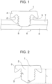
- Figs. 1 and 3 are schematic illustrations each showing a state in which a sheet set including two metal sheets is joined using an element.
- Fig. 3 shows a conventional element, and the conventional element has no screw thread on the side surface of its mandrel.
- Fig. 1 shows the friction joining element of the invention (which may be hereinafter referred to as an "element"), and the friction joining element of the invention has a screw thread on the side surface of its mandrel.
- the same components are denoted by the same numerals.
- numeral 1 denotes an element
- numeral 2 denotes a mandrel.
- Numeral 3 denotes a collar
- numeral 5 denotes a screw thread
- Numeral 6 denotes a sheet set
- Numeral 7 denotes an upper sheet
- numeral 8 denotes a lower sheet
- Numeral 9 denotes the joint interface between the element and the lower sheet.
- Figs. 1 and 3 each show a state in which a sheet set 6 including two sheet-shaped members (an upper sheet 7 and a lower sheet 8) and an element 1 are joined together.
- the upper sheet 7 is the uppermost one of the stacked metal sheets forming the sheet set 6, and the lower sheet 8 is the lowermost one of the stacked metal sheets forming the sheet set 6.
- the upper sheet 7 is a high strength steel sheet containing ultra-high strength steel.
- the term "high strength" means that the tensile strength is 590 MPa or more.
- the tensile strength of the steel sheet is preferably 980 MPa or more and is preferably 1470 MPa or less.
- a joining apparatus (not shown) is used to join the sheet set 6 using the element 1.
- the element 1 is rotated and brought into contact with the upper sheet 7 that is one of the sheet-shaped members, and a pressing force is applied to the element 1 to press the element 1 into the upper sheet 7.
- the upper sheet 7 that is one of the sheet-shaped members is plasticized by the frictional heat, and the mandrel 2 enters the upper sheet 7 that is one of the sheet-shaped members.
- the element 1 pierces through the upper sheet 7 that is one of the sheet-shaped members and comes into contact with the lower sheet 8 that is another of the sheet-shaped members, and then a friction joining process is started in the element 1 and the lower sheet 8.
- the joint between the upper sheet 7 and the lower sheet 8 is achieved by the element 1.
- the joint state is insufficient. This is because of the following reason. Since the metal sheet such as the steel sheet is less easily plastically deformed than a light metal sheet such as an aluminum sheet, the gap between the collar portion of the element and the upper sheet is not fully filled with the plastically deformed metal.
- the screw thread 5 continuously formed in the length direction of the mandrel 2 is provided on the side surface of the mandrel 2.
- the screw thread 5 engages the upper sheet 7 that is one of the sheet-shaped members, and the upper sheet 7 that is one of the sheet-shaped members is fastened to the mandrel 2. Therefore, the upper sheet 7 is plastically deformed sufficiently, and the collar 3 of the element 1 and the upper sheet 7 come into contact with each other.
- the mandrel 2 pierces through the upper sheet 7 that is one of the sheet-shaped members and enters the lower sheet 8, and the forward end of the mandrel 2 is connected to the lower sheet 8 by friction joining.
- the material of the upper sheet 7 is plastically deformed and extruded in the joining process, and the extruded material is held by the collar 3 disposed at the upper portion of the mandrel 2. Therefore, the mechanical joint between the upper sheet 7 that is one of the sheet-shaped members and the lower sheet 8 that is the other one of the sheet-shaped members can be achieved by the element 1.
- the upper sheet 7 and the screw thread 5 engage each other as shown in Fig. 1 . Therefore, even when the upper sheet 7 is a high strength steel sheet, a sound joint state is obtained.
- the element of the invention is used to mechanically join a sheet set prepared by stacking two or more metal sheets including a high strength steel sheet as an upper sheet.
- Fig. 2 is a schematic illustration showing one embodiment of the element of the invention.
- the element 1 of the invention includes the mandrel 2 and the collar 3, and the screw thread 5 is provided on the side surface of the mandrel 2.
- the screw thread 5 includes a plurality of ridges formed continuously in the length direction of the mandrel.
- the element 1 is rotated at high speed, pressed into the sheet set, and connected to the sheet set. As described above, the element 1 is joined to the upper sheet of the sheet set through the screw thread and frictionally joined to the lower sheet of the sheet set at the forward end of the mandrel.
- the mandrel 2 is disposed at the axial center of the element 1 and formed into a cylindrical shape.
- the forward end of the mandrel 2 is formed into a flat shape, a tapered shape inclined such that its forward end portion protrudes forward, a drill shape having cutting edges, etc.
- the overall length L of the mandrel 2 is adjusted to be equal to or less than the total thickness of the sheet set (the total thickness of the sheets in the sheet set 6).
- the upper limit of the overall length of the mandrel 2 is the same as the total thickness of the sheet set 6 or is a value obtained by subtracting the thickness of the lowermost metal sheet (lowermost layer) in the sheet set (for example, the lower sheet 8 in the example shown in Fig. 1 ) from the total thickness of the sheet set 6. It is only necessary that the overall length L of the mandrel 2 be such that the forward end of the mandrel can be frictionally jointed to the lower sheet 8.
- the overall length L (mm) of the mandrel 2 is preferably 10 mm or less and more preferably 8 mm or less.
- the overall length L of the mandrel 2 is preferably 1 mm or more.
- the screw thread 5 is provided on the side surface of the mandrel 2.
- the screw thread 5 is provided on the side surface of a head-side portion (upper-side portion) of the mandrel 2 (i.e., a head-side portion of the element 1).
- three ridges are provided around the head-side portion of the mandrel 2.
- the screw thread 5 and the upper sheet 7 that is one of the sheet-shaped members engage each other, and the effect of fastening the upper sheet 7 to the mandrel 2 is obtained. Therefore, so long as this effect is obtained, the screw thread can have any shape.
- the number of ridges of the screw thread can be appropriately adjusted in consideration of the material and strength of the metal sheets forming the sheet set 6, the total number of metal sheet forming the sheet set, etc.
- the surface of the screw thread 5 may be subjected to coating treatment to form a coating layer.
- wear of the screw thread 5 that occurs when the screw thread 5 enters the upper sheet 7 that is one of the sheet-shaped members can be reduced. Therefore, the element 1 and the upper sheet 7 that is one of the sheet-shaped members can more firmly engage each other.
- the coating layer includes coating layers formed of WC, TiN, and other ceramics, heat-resistant coating layers, and coating layers formed by hardening treatment such as nitriding.
- the thickness of the coating layer may be appropriately adjusted according to the desired performance.
- the collar 3 is disposed at a portion on top of the mandrel 2, i.e., a head portion of the element 1. In this manner, the material of the upper sheet 7 extruded due to the plastic flow during the joining process can be held by the collar 3.
- the collar 3 may be formed into, for example, a wafer shape, a truss shape, etc.
- the element 1 of the invention having the structure described above is rotated and pressed into the sheet set 6 as shown in, for example, Fig. 1 , and the metal sheets (the upper sheet 7 and the lower sheet 8) are plasticized by the frictional heat generated during this process. Then the upper sheet 7 of the sheet set 6 and the screw thread 5 formed on the side surface of the mandrel 2 engage each other and fastened together, and the lower sheet 8 of the sheet set 6 is frictionally joined to the forward end of the mandrel 2, so that a joint can be obtained by mechanical joining. With the element 1 of the invention, the effect of strengthening the fastening of the sheet-shaped members (the upper sheet 7 and the lower sheet 8) can be obtained.
- the sheet set 6 shown includes two metal sheets. However, a sheet set including three or more metal sheets may be used.
- the uppermost sheet 7 in the sheet set 6 including two or more metal sheets is a steel sheet (high strength steel sheet) containing ultra-high strength steel.
- the screw thread 5 is important to provide the screw thread 5 on the side surface of the mandrel 2.
- the screw thread 5 has the following shape.
- the screw thread 5 is disposed in a side surface region of the mandrel 2 in the length direction of the mandrel 2.
- the metal sheet used as the upper sheet 7 and the screw thread 5 can form an engagement portion.
- the number of ridges of the screw thread 5 in the side surface region is preferably in the range of 2 to 20. This allows the formation of the engagement portion.
- the number of ridges of the screw thread 5 is preferably 3 or more and is preferably 10 or less.
- the distance (pitch) between adjacent ridges of the screw thread 5 is preferably in the range of 100 to 1000 um.
- the "distance between adjacent ridges of the screw thread" is the distance between ridges adjacent in the length direction of the mandrel 2. If this distance is less than 100 um, the sheet material is not easily engaged between ridges of the screw thread, and therefore the engagement portion with the metal sheet (the upper sheet 7) cannot be obtained. If the distance exceeds 1000 um, the area of contact between the element and the metal sheet (the upper sheet 7) in the engagement portion is small, and therefore the above effect cannot be obtained.
- the distance between adjacent ridges of the screw thread 5 is preferably in the range of 100 to 500 ⁇ m.
- the inclination angle ⁇ 1 of the screw thread 5 is preferably 10 to 180°.
- the "inclination angle ⁇ 1 of the screw thread" is the angle of the crest of the screw thread. If the inclination angle ⁇ 1 is less than 10°, the width of the screw thread is small, and the object of the invention is not obtained. If the inclination angle ⁇ 1 exceeds 180°, no screw thread is present, or the ridges and valleys are inverted.
- the inclination angle ⁇ 1 is preferably 30° or more and is preferably 90° or less.
- the forward end of the mandrel 2 is formed into the shape described above.
- the forward end portion has a tapered shape protruding forward.
- the angle ⁇ 2 of the tapered shape is preferably 120 to 180°.
- the collar 3 has the function of holding the material of the upper sheet 7 extruded by the plastic flow during the joining process. To obtain this effect, it is necessary that the collar 3 form a space for storing the metal extruded by the plastic flow and press the upper sheet 7. Therefore, as shown in Fig. 2 , it is preferable that the collar 3 is formed into an umbrella shape.
- the thickness of the coating layer is preferably 1 to 100 um. If the thickness is less than 1 ⁇ m, the coating layer may disappear due to wear, so that the effect of the coating may not be obtained. A thickness of more than 100 um is not practical from the viewpoint of cost.
- the thickness of the coating layer is more preferably 2 um or more and is more preferably 10 um or less.
- the "590 MPa-grade” means that the lower limit of the tensile strength is 590 MPa, and the “980 MPa-grade” means that the lower limit of the tensile strength is 980 MPa.
- the "1180 MPa-grade” means that the lower limit of the tensile strength is 1180 MPa, and the “1470 MPa-grade” means that the lower limit of the tensile strength is 1470 MPa.
- the thicknesses h (mm) of the samples are shown in Tables 1-1 and 1-2. In the Examples, the sheet sets shown in Tables 1-1 and 1-2 were used.
- the "heat-resistant film” in Table 2 is a coating layer that is a heat-resistant coating formed by PVD treatment.
- Each of the sheet sets was joined using a joining method known as the friction element welding (FEW) method (see, for example, U.S. patent NO. 3,477,115 ).
- the joining conditions used are shown in Table 2.
- the joints obtained by the joining were used for joint appearance observation and a tensile strength test using the following methods. The results obtained were used to evaluate the joint state according to criteria described below.
- the appearance observation was performed by visually observing each of the joints obtained. Moreover, the joint was cut at the center of its joint portion to obtain a cross section, and the cross section was observed. The appearance of the joint was evaluated as follows. When the element pierced through the upper sheet and was frictionally joined to the lower sheet, the appearance of the joint was rated "good,” and the symbol "o” was assigned. In other cases, the appearance of the joint was rated “poor,” and the symbol "x” was assigned. The results obtained are shown in Table 2.
- each of the joints obtained was used to perform a cross tensile test (JIS Z 3137).
- the cross tensile test was performed on the joints whose appearance had been rated "good” in the appearance observation.
- the joint strength (kN) obtained is shown in Table 2.
- the evaluation of the joint state was one of A to C, and thus, the joint could be formed using mechanical joining.
- the joints obtained (except for Nos. 12 and 16 in Table 2) were found to have good joint performance.
- the evaluation of the joint state was D in all the cases, and thus, the joint could not be formed by mechanical joining.
- the joint state was good, and the joint strength was 2.6 kN or more.
- the joint strength was as low as 1.5 kN.
- the joint state was poor (the joint appearance in Table 2 was represented by the symbol " ⁇ ").
Landscapes
- Engineering & Computer Science (AREA)
- General Engineering & Computer Science (AREA)
- Mechanical Engineering (AREA)
- Pressure Welding/Diffusion-Bonding (AREA)
- Connection Of Plates (AREA)
Abstract
Description
- The present invention relates to a friction joining element. In the present invention, the friction joining element is rotated at high speed and pressed into a sheet set including two or more metal sheets including a high strength steel sheet as an upper sheet to thereby join the sheet set by friction joining.
- In recent years, high strength steel sheets called ultra-high strength steel sheets are increasingly used in the automobile industry in order to achieve simultaneously safety and a reduction in environmental loads by reducing the weight of automobile bodies, and further, steel sheets having higher strength and higher workability are expected to be developed in the future. However, one problem that occurs when fusion bonding such as resistance spot welding is applied to steel sheets with increased strength and workability is a reduction in joint strength due to embrittlement of solidification microstructures. Therefore, attention is given to a non-fusion bonding technique capable of bonding high strength steel sheets together.
- One example of the non-fusion bonding technique that has been contemplated is FEW (Friction Element Welding) described in
Reference Literature 1. In the FEW technique, an element rotated at high speed is pressed into a sheet set to join the sheet set. For example, a method proposed and disclosed inPatent Literature 1 has been used for the element. - [Reference Literature 1] Jamie D. Skovron, Brandt J. Ruszkiewicz, and Laine Mears, "INVESTIGATION OF THE CLEANING AND WELDING STEPS FROM THE FRICTION ELEMENT WELDING PROCESS" (ASME 2017 12th International Manufacturing Science and Engineering Conference collocated with the JSME/ASME 2017 6th International Conference on Materials and Processing, June 4-8, 2017, Los Angeles, California, USA)
In the technique disclosed inPatent Literature 1, the forward end of a mandrel portion of a joining element (element) is connected to a lower sheet by friction welding. Then an upper sheet material plastically deformed and extruded in the joining process is held by a collar of a head portion of the element, and joining of the sheet set is thereby achieved. - PTL 1: Japanese Unexamined Patent Application Publication (Translation of
PCT Application) No. 2013-534994 - It is stated in
Patent Literature 1 that, for example, an aluminum sheet is used as the upper sheet included in the sheet set and a steel sheet is used as the lower sheet in the sheet set. However, with the technique described inPatent Literature 1, when a steel sheet is used as the upper sheet, the plastic deformation of the upper sheet is insufficient, and therefore the collar of the joining element (element) does not come into contact with the upper sheet, so that the element cannot fasten the upper sheet sufficiently. Therefore, it may be difficult to join the sheet set in some cases. - The present invention has been made to solve the foregoing problem, and it is an object to provide a friction joining element capable of mechanically joining a sheet set including two or more stacked metal sheets including a high strength steel sheet as an upper sheet.
- The inventors have conducted extensive studies to solve the foregoing problem. Then the inventors have found that, by specially designing the shape of the side surface of the friction joining element, a sheet set including two or more metal sheets can be joined using mechanical joining even when the sheet set is, in particular, a sheet set including two or more metal sheets including, as an upper sheet, a steel sheet containing ultra-high strength steel (high strength steel sheet).
- Specifically, a screw thread is formed on the side surface of the mandrel of the friction joining element, and this allows the friction joining element to engage the upper sheet. In this manner, even when a high strength steel sheet is used as the upper sheet of the sheet set, the friction joining element can firmly fasten the upper sheet, and the sheet set can be joined together using mechanical joining.
- The present invention has been made on the basis of the above findings and completed as a result of further studies. The present invention is summarized as follows.
- [1] A friction joining element for mechanically joining a sheet set prepared by stacking two or more metal sheets including a high strength steel sheet as an upper sheet,
- the friction joining element including: a mandrel having an overall length adjusted to be equal to or less than the total thickness of the sheet set; and a collar disposed at an upper portion of the mandrel,
- wherein the friction joining element has a screw thread on a side surface of a head-side portion of the mandrel.
- [2] The friction joining element according to [1], wherein a coating layer is provided on a surface of the screw thread.
- [3] The friction joining element according to [1] or [2], wherein the number of ridges of the screw thread in a side surface region of the mandrel is from 2 to 20 inclusive, and wherein the distance between adjacent ridges of the screw thread is in the range of 100 to 1000 um. Advantageous Effects of Invention
- In the present invention, the friction joining element of the invention and a sheet set are fastened together by screwing. Therefore, even when the sheet set includes two or more metal sheets including a high strength steel sheet as an upper sheet, the sheet set can be joined by mechanical joining. In this manner, a mechanically joined joint having good joint performance can be provided.
-
- [Fig. l]
Fig. 1 is a schematical illustration showing a joint state obtained using the friction joining element of the invention. - [
Fig. 2] Fig. 2 is a schematic illustration showing an embodiment of the friction joining element of the invention. - [
Fig. 3] Fig. 3 is a schematic illustration showing a joint state obtained using a conventional element. Description of Embodiments - The present invention will next be described in detail.
- First, the technological idea of the invention will be described.
-
Figs. 1 and3 are schematic illustrations each showing a state in which a sheet set including two metal sheets is joined using an element.Fig. 3 shows a conventional element, and the conventional element has no screw thread on the side surface of its mandrel.Fig. 1 shows the friction joining element of the invention (which may be hereinafter referred to as an "element"), and the friction joining element of the invention has a screw thread on the side surface of its mandrel. InFigs. 1 and3 , the same components are denoted by the same numerals. In each ofFigs. 1 and3 ,numeral 1 denotes an element, andnumeral 2 denotes a mandrel. Numeral 3 denotes a collar, andnumeral 5 denotes a screw thread. Numeral 6 denotes a sheet set. Numeral 7 denotes an upper sheet, andnumeral 8 denotes a lower sheet. Numeral 9 denotes the joint interface between the element and the lower sheet. -
Figs. 1 and3 each show a state in which a sheet set 6 including two sheet-shaped members (anupper sheet 7 and a lower sheet 8) and anelement 1 are joined together. Theupper sheet 7 is the uppermost one of the stacked metal sheets forming thesheet set 6, and thelower sheet 8 is the lowermost one of the stacked metal sheets forming thesheet set 6. Theupper sheet 7 is a high strength steel sheet containing ultra-high strength steel. In the present invention, the term "high strength" means that the tensile strength is 590 MPa or more. The tensile strength of the steel sheet is preferably 980 MPa or more and is preferably 1470 MPa or less. - As shown in
Figs. 1 and3 , to join thesheet set 6 using theelement 1, first, a joining apparatus (not shown) is used. Specifically, theelement 1 is rotated and brought into contact with theupper sheet 7 that is one of the sheet-shaped members, and a pressing force is applied to theelement 1 to press theelement 1 into theupper sheet 7. In this manner, theupper sheet 7 that is one of the sheet-shaped members is plasticized by the frictional heat, and themandrel 2 enters theupper sheet 7 that is one of the sheet-shaped members. Theelement 1 pierces through theupper sheet 7 that is one of the sheet-shaped members and comes into contact with thelower sheet 8 that is another of the sheet-shaped members, and then a friction joining process is started in theelement 1 and thelower sheet 8. - In the case of the
conventional element 1 shown inFig. 3 , the joint between theupper sheet 7 and thelower sheet 8 is achieved by theelement 1. However, when a cross section of the joint portion is observed, a gap is present between thecollar 3 of theelement 1 and theupper sheet 7, and therefore the joint state is insufficient. This is because of the following reason. Since the metal sheet such as the steel sheet is less easily plastically deformed than a light metal sheet such as an aluminum sheet, the gap between the collar portion of the element and the upper sheet is not fully filled with the plastically deformed metal. - However, in the case of the
element 1 of the invention shown inFig. 1 , thescrew thread 5 continuously formed in the length direction of themandrel 2 is provided on the side surface of themandrel 2. In this manner, as themandrel 2 enters theupper sheet 7 that is one of the sheet-shaped members, thescrew thread 5 engages theupper sheet 7 that is one of the sheet-shaped members, and theupper sheet 7 that is one of the sheet-shaped members is fastened to themandrel 2. Therefore, theupper sheet 7 is plastically deformed sufficiently, and thecollar 3 of theelement 1 and theupper sheet 7 come into contact with each other. - Moreover, the
mandrel 2 pierces through theupper sheet 7 that is one of the sheet-shaped members and enters thelower sheet 8, and the forward end of themandrel 2 is connected to thelower sheet 8 by friction joining. In this case, the material of theupper sheet 7 is plastically deformed and extruded in the joining process, and the extruded material is held by thecollar 3 disposed at the upper portion of themandrel 2. Therefore, the mechanical joint between theupper sheet 7 that is one of the sheet-shaped members and thelower sheet 8 that is the other one of the sheet-shaped members can be achieved by theelement 1. When a cross section of the joint portion obtained by the element of the invention is observed, theupper sheet 7 and thescrew thread 5 engage each other as shown inFig. 1 . Therefore, even when theupper sheet 7 is a high strength steel sheet, a sound joint state is obtained. - Next, referring to
Fig. 2 , the element of the invention will be described. - The element of the invention is used to mechanically join a sheet set prepared by stacking two or more metal sheets including a high strength steel sheet as an upper sheet.
-
Fig. 2 is a schematic illustration showing one embodiment of the element of the invention. As shown inFig. 2 , theelement 1 of the invention includes themandrel 2 and thecollar 3, and thescrew thread 5 is provided on the side surface of themandrel 2. Thescrew thread 5 includes a plurality of ridges formed continuously in the length direction of the mandrel. Theelement 1 is rotated at high speed, pressed into the sheet set, and connected to the sheet set. As described above, theelement 1 is joined to the upper sheet of the sheet set through the screw thread and frictionally joined to the lower sheet of the sheet set at the forward end of the mandrel. - The
mandrel 2 is disposed at the axial center of theelement 1 and formed into a cylindrical shape. The forward end of themandrel 2 is formed into a flat shape, a tapered shape inclined such that its forward end portion protrudes forward, a drill shape having cutting edges, etc. - The overall length L of the
mandrel 2 is adjusted to be equal to or less than the total thickness of the sheet set (the total thickness of the sheets in the sheet set 6). Specifically, the upper limit of the overall length of themandrel 2 is the same as the total thickness of the sheet set 6 or is a value obtained by subtracting the thickness of the lowermost metal sheet (lowermost layer) in the sheet set (for example, thelower sheet 8 in the example shown inFig. 1 ) from the total thickness of the sheet set 6. It is only necessary that the overall length L of themandrel 2 be such that the forward end of the mandrel can be frictionally jointed to thelower sheet 8. - The overall length L (mm) of the
mandrel 2 is preferably 10 mm or less and more preferably 8 mm or less. The overall length L of themandrel 2 is preferably 1 mm or more. - The
screw thread 5 is provided on the side surface of themandrel 2. Thescrew thread 5 is provided on the side surface of a head-side portion (upper-side portion) of the mandrel 2 (i.e., a head-side portion of the element 1). In the example shown inFig. 2 , three ridges are provided around the head-side portion of themandrel 2. In the present invention, it is important that thescrew thread 5 be disposed on the side surface of themandrel 2. In this case, as described above, thescrew thread 5 and theupper sheet 7 that is one of the sheet-shaped members engage each other, and the effect of fastening theupper sheet 7 to themandrel 2 is obtained. Therefore, so long as this effect is obtained, the screw thread can have any shape. The number of ridges of the screw thread can be appropriately adjusted in consideration of the material and strength of the metal sheets forming the sheet set 6, the total number of metal sheet forming the sheet set, etc. - The surface of the
screw thread 5 may be subjected to coating treatment to form a coating layer. In this case, wear of thescrew thread 5 that occurs when thescrew thread 5 enters theupper sheet 7 that is one of the sheet-shaped members can be reduced. Therefore, theelement 1 and theupper sheet 7 that is one of the sheet-shaped members can more firmly engage each other. - No particular constraint is imposed on the coating layer so long as it has the desired performance as a wear resistance material. Examples of the coating layer include coating layers formed of WC, TiN, and other ceramics, heat-resistant coating layers, and coating layers formed by hardening treatment such as nitriding. The thickness of the coating layer may be appropriately adjusted according to the desired performance.
- The
collar 3 is disposed at a portion on top of themandrel 2, i.e., a head portion of theelement 1. In this manner, the material of theupper sheet 7 extruded due to the plastic flow during the joining process can be held by thecollar 3. Specifically, thecollar 3 may be formed into, for example, a wafer shape, a truss shape, etc. - The
element 1 of the invention having the structure described above is rotated and pressed into the sheet set 6 as shown in, for example,Fig. 1 , and the metal sheets (theupper sheet 7 and the lower sheet 8) are plasticized by the frictional heat generated during this process. Then theupper sheet 7 of the sheet set 6 and thescrew thread 5 formed on the side surface of themandrel 2 engage each other and fastened together, and thelower sheet 8 of the sheet set 6 is frictionally joined to the forward end of themandrel 2, so that a joint can be obtained by mechanical joining. With theelement 1 of the invention, the effect of strengthening the fastening of the sheet-shaped members (theupper sheet 7 and the lower sheet 8) can be obtained. - In the example shown in
Fig. 1 , the sheet set 6 shown includes two metal sheets. However, a sheet set including three or more metal sheets may be used. Theuppermost sheet 7 in the sheet set 6 including two or more metal sheets is a steel sheet (high strength steel sheet) containing ultra-high strength steel. - The embodiment of the
element 1 of the invention will next be described in detail. - As described above, in the present invention, it is important to provide the
screw thread 5 on the side surface of themandrel 2. Preferably, thescrew thread 5 has the following shape. - Preferably, the
screw thread 5 is disposed in a side surface region of themandrel 2 in the length direction of themandrel 2. In this case, the metal sheet used as theupper sheet 7 and thescrew thread 5 can form an engagement portion. The number of ridges of thescrew thread 5 in the side surface region is preferably in the range of 2 to 20. This allows the formation of the engagement portion. The number of ridges of thescrew thread 5 is preferably 3 or more and is preferably 10 or less. - The distance (pitch) between adjacent ridges of the
screw thread 5 is preferably in the range of 100 to 1000 um. The "distance between adjacent ridges of the screw thread" is the distance between ridges adjacent in the length direction of themandrel 2. If this distance is less than 100 um, the sheet material is not easily engaged between ridges of the screw thread, and therefore the engagement portion with the metal sheet (the upper sheet 7) cannot be obtained. If the distance exceeds 1000 um, the area of contact between the element and the metal sheet (the upper sheet 7) in the engagement portion is small, and therefore the above effect cannot be obtained. The distance between adjacent ridges of thescrew thread 5 is preferably in the range of 100 to 500 µm. - The inclination angle θ1 of the
screw thread 5 is preferably 10 to 180°. The "inclination angle θ1 of the screw thread" is the angle of the crest of the screw thread. If the inclination angle θ1 is less than 10°, the width of the screw thread is small, and the object of the invention is not obtained. If the inclination angle θ1 exceeds 180°, no screw thread is present, or the ridges and valleys are inverted. The inclination angle θ1 is preferably 30° or more and is preferably 90° or less. - The forward end of the
mandrel 2 is formed into the shape described above. In the example shown inFig. 2 , the forward end portion has a tapered shape protruding forward. The angle θ2 of the tapered shape is preferably 120 to 180°. - As described above, the
collar 3 has the function of holding the material of theupper sheet 7 extruded by the plastic flow during the joining process. To obtain this effect, it is necessary that thecollar 3 form a space for storing the metal extruded by the plastic flow and press theupper sheet 7. Therefore, as shown inFig. 2 , it is preferable that thecollar 3 is formed into an umbrella shape. - The thickness of the coating layer is preferably 1 to 100 um. If the thickness is less than 1 µm, the coating layer may disappear due to wear, so that the effect of the coating may not be obtained. A thickness of more than 100 um is not practical from the viewpoint of cost.
- The thickness of the coating layer is more preferably 2 um or more and is more preferably 10 um or less.
- To further facilitate the understanding of the present invention, the invention will be described by way of Examples. However, the following Examples do not limit the present invention and are included in the technical scope of the invention so long as they satisfy the gist of the invention.
- In samples used, 590 MPa-grade high-strength steel, 980 MPa-grade high-strength steel, 1470 MPa-grade high-strength steel, or an A5052 aluminum alloy was used for the upper sheet, and 1180 MPa-grade high-strength steel or 1470 MPa-grade high-strength steel was used for the lower sheet. For sheet sets including three sheets, 980 MPa-grade high-strength steel, 1470 MPa-grade high-strength steel, or an A5052 aluminum alloy was used for the middle sheet.
- The "590 MPa-grade" means that the lower limit of the tensile strength is 590 MPa, and the "980 MPa-grade" means that the lower limit of the tensile strength is 980 MPa. The "1180 MPa-grade" means that the lower limit of the tensile strength is 1180 MPa, and the "1470 MPa-grade" means that the lower limit of the tensile strength is 1470 MPa. The thicknesses h (mm) of the samples are shown in Tables 1-1 and 1-2. In the Examples, the sheet sets shown in Tables 1-1 and 1-2 were used.
- Two types of elements shown in Table 2 were prepared as elements for joining the above sheet sets. One of them is the element shown in
Fig. 1 and including the screw thread disposed on the side surface of the mandrel 2 (the element of the invention). The other one is the element shown inFig. 3 and including no screw thread on the side surface of the mandrel (the conventional element). In the forward end of themandrel 2 shown inFig. 1 , the angle θ2 of the tapered shape was appropriately set within the range of 120 to 180° (seeFig. 2 ). The "heat-resistant film" in Table 2 is a coating layer that is a heat-resistant coating formed by PVD treatment. - Each of the sheet sets was joined using a joining method known as the friction element welding (FEW) method (see, for example,
U.S. patent NO. 3,477,115 ). The joining conditions used are shown in Table 2. - The joints obtained by the joining (mechanically joined joints) were used for joint appearance observation and a tensile strength test using the following methods. The results obtained were used to evaluate the joint state according to criteria described below.
- The appearance observation was performed by visually observing each of the joints obtained. Moreover, the joint was cut at the center of its joint portion to obtain a cross section, and the cross section was observed. The appearance of the joint was evaluated as follows. When the element pierced through the upper sheet and was frictionally joined to the lower sheet, the appearance of the joint was rated "good," and the symbol "o" was assigned. In other cases, the appearance of the joint was rated "poor," and the symbol "x" was assigned. The results obtained are shown in Table 2.
- In the tensile strength test, each of the joints obtained was used to perform a cross tensile test (JIS Z 3137). The cross tensile test was performed on the joints whose appearance had been rated "good" in the appearance observation. The joint strength (kN) obtained is shown in Table 2.
- The joint state was evaluated using the above results according to the following criteria.
- When the rating of the appearance of the joint was "o" and the joint strength was "6 kN or more," the joint state was rated "A." When the rating of the appearance of the joint was "o" and the joint strength was "3 kN or more and less than 6 kN," the joint state was rated "B." When the rating of the appearance of the joint was "o" and the joint strength was "less than 3 kN," the joint state was rated "C." When the rating of the appearance of the joint was "×," the joint state was rated "D." The results of the evaluation of the joint state are shown in Table 2.
[Table 1-1] Sheet set Lower sheet Upper sheet Material Thickness h (mm) Material Thickness h (mm) a 1470 MPa grade 1.6 980 MPa grade 1.0 b 1470 MPa grade 1.6 980 MPa grade 1.6 c 1470 MPa grade 1.6 1470 MPa grade 1.0 d 1180 MPa grade 1.6 980 MPa grade 1.0 e 1470 MPa grade 1.0 980 MPa grade 1.0 f 1470 MPa grade 1.6 A5052 2.0 [Table 1-2] Sheet set Lower sheet Middle sheet Upper sheet Material Thickness h (mm) Material Thickness h (mm) Material Thickness h (mm) 9 1470 MPa grade 1.6 A5052 1.0 A5052 0.5 h 1470 MPa grade 1.6 980 MPa grade 0.5 590 MPa grade 0.5 i 1470 MPa grade 1.0 1470 MPa grade 0.5 980 MPa grade 0.5 [Table 2] No. Sheet set Element shape Joining conditions Evaluation Remarks Element Overall length L of mandrel (mm) Number of ridges of screw thread (-) Pitch (µm) Inclination angle of screw thread θ1 (°) Coating Rotation speed (rpm) Pressing force (kN) Appearance of joint*1 Joint strength (kN) Joint state*2 Presence of coating Type Thickness (µm) 1 a Fig. 1 4 6 400 60 Yes Heat resistant film 5 6500 7 ○ 7.4 A Inventive Example 2 a Fig. 1 4 6 400 60 No - - 6500 7 ○ 5.3 B Inventive Example 3 a Fig. 3 4 6 400 60 No - - 6500 7 × - D Comparative Example 4 b Fig. 1 5 8 400 60 Yes Heat resistant film 5 6500 7 ○ 2.6 C Inventive Example 5 b Fig. 3 5 8 400 60 No - - 6500 7 × - D Comparative Example 6 c Fig. 1 4 6 400 60 Yes Heat resistant film 5 6500 7 ○ 5.6 B Inventive Example 7 c Fig. 3 4 6 400 60 No - - 6500 7 × - D Comparative Example 8 d Fig. 1 4 6 400 60 Yes Heat resistant film 5 6500 7 ○ 7.2 A Inventive Example 9 d Fig. 3 4 6 400 60 No - - 6500 7 × - D Comparative Example 10 e Fig. 1 4 6 400 60 Yes Heat resistant film 5 6500 7 ○ 6.7 A Inventive Example 11 e Fig. 3 4 6 400 60 No - - 6500 7 × - D Comparative Example 12 f Fig. 1 5 8 400 60 Yes Heat resistant film 5 6500 7 ○ 1.5 C Comparative Example 13 a Fig. 1 4 6 400 60 Yes Heat resistant film 3 6500 7 ○ 7.4 A Inventive Example 14 a Fig. 1 4 6 400 60 Yes Heat resistant film 1 6500 7 ○ 5.3 B Inventive Example 15 a Fig. 1 4 6 400 60 Yes Heat resistant film 11 6500 7 ○ 7.4 A Inventive Example 16 9 Fig. 1 4 6 400 60 Yes Heat resistant film 5 6500 7 ○ 1.5 C Comparative Example 17 h Fig. 1 4 6 400 60 Yes Heat resistant film 5 6500 7 ○ 7.4 A Inventive Example 18 i Fig. 1 4 6 400 60 Yes Heat resistant film 5 6500 7 ○ 6.7 A Inventive Example *1. ∘: The appearance of the joint was good. ×: The appearance of the joint was poor.
*2. A: The appearance of the joint was "∘," and the joint strength was "6 kN or more."
B: The appearance of the joint was "∘," and the joint strength was "3 kN or more and less than 6 kN."
C: The appearance of the joint was "∘," and the joint strength was "less than 3 kN." D: The appearance of the joint was "x." - When the joining was performed using the element of the invention, the evaluation of the joint state was one of A to C, and thus, the joint could be formed using mechanical joining. The joints obtained (except for Nos. 12 and 16 in Table 2) were found to have good joint performance. However, when the conventional element was used for joining, the evaluation of the joint state was D in all the cases, and thus, the joint could not be formed by mechanical joining.
- As shown in Table 2, in all the Inventive Examples, the joint state was good, and the joint strength was 2.6 kN or more. However, in joints Nos. 12 and 16 (Comparative Examples), although the appearance evaluation of the joint was good "∘," since the upper sheet was the aluminum alloy sheet, the wear of the element during insertion into the upper sheet was significant, and the joint diameter was not sufficient. Therefore, the joint strength was as low as 1.5 kN. In the Comparative Examples outside the ranges of the invention, the joint state was poor (the joint appearance in Table 2 was represented by the symbol "×").
-
- 1
- element
- 2
- mandrel
- 3
- collar
- 5
- screw thread
- 6
- sheet set
- 7
- upper sheet
- 8
- lower sheet
- 9
- joint interface between element and lower sheet
Claims (3)
- A friction joining element for mechanically joining a sheet set prepared by stacking two or more metal sheets including a high strength steel sheet as an upper sheet,the friction joining element comprising: a mandrel having an overall length adjusted to be equal to or less than the total thickness of the sheet set; and a collar disposed at an upper portion of the mandrel,wherein the friction joining element has a screw thread on a side surface of a head-side portion of the mandrel.
- The friction joining element according to claim 1,
wherein a coating layer is provided on a surface of the screw thread. - The friction joining element according to claim 1 or 2, wherein the number of ridges of the screw thread in a side surface region of the mandrel is from 2 to 20 inclusive, and wherein the distance between adjacent ridges of the screw thread is in the range of 100 to 1000 um.
Applications Claiming Priority (2)
| Application Number | Priority Date | Filing Date | Title |
|---|---|---|---|
| JP2021048713 | 2021-03-23 | ||
| PCT/JP2022/012435 WO2022202631A1 (en) | 2021-03-23 | 2022-03-17 | Friction joining element |
Publications (2)
| Publication Number | Publication Date |
|---|---|
| EP4275828A1 true EP4275828A1 (en) | 2023-11-15 |
| EP4275828A4 EP4275828A4 (en) | 2025-01-08 |
Family
ID=83395746
Family Applications (1)
| Application Number | Title | Priority Date | Filing Date |
|---|---|---|---|
| EP22775419.9A Pending EP4275828A4 (en) | 2021-03-23 | 2022-03-17 | Friction joining element |
Country Status (7)
| Country | Link |
|---|---|
| US (1) | US12429080B2 (en) |
| EP (1) | EP4275828A4 (en) |
| JP (1) | JP7327678B2 (en) |
| KR (1) | KR102902202B1 (en) |
| CN (1) | CN116981533A (en) |
| MX (1) | MX2023011091A (en) |
| WO (1) | WO2022202631A1 (en) |
Families Citing this family (1)
| Publication number | Priority date | Publication date | Assignee | Title |
|---|---|---|---|---|
| JP7508030B1 (en) * | 2022-11-24 | 2024-07-01 | Jfeスチール株式会社 | Friction element joining method |
Family Cites Families (15)
| Publication number | Priority date | Publication date | Assignee | Title |
|---|---|---|---|---|
| US3477115A (en) | 1967-03-17 | 1969-11-11 | Caterpillar Tractor Co | Method of fastening parts by friction welding |
| JP4092794B2 (en) * | 1998-11-02 | 2008-05-28 | 日本軽金属株式会社 | Joining method |
| US6769595B2 (en) * | 2000-12-20 | 2004-08-03 | Alcoa Inc. | Friction plunge riveting |
| US7942306B2 (en) * | 2007-04-13 | 2011-05-17 | Wichita State University | Friction stir welding tool having a counterflow pin configuration |
| DE102010017550A1 (en) | 2010-06-23 | 2011-12-29 | Ejot Gmbh & Co. Kg | Connecting element for a friction-welded connection for connecting at least two plate-like components |
| DE102013220863A1 (en) | 2013-10-15 | 2015-04-16 | Robert Bosch Gmbh | Connecting element for connecting at least two plate-like components and composite component |
| US9808856B2 (en) | 2014-09-25 | 2017-11-07 | GM Global Technology Operations LLC | Apparatus and methods for reducing corrosion of joining composite workpieces |
| DE102015202074A1 (en) | 2015-02-05 | 2016-08-11 | Ejot Gmbh & Co. Kg | Connecting element for producing a component connection |
| DE102016205924A1 (en) | 2016-04-08 | 2017-10-12 | Ford Global Technologies, Llc | Method for producing a hybrid connection and device therefor |
| DE102016115463A1 (en) | 2016-08-19 | 2018-02-22 | Ejot Gmbh & Co. Kg | Method for connecting at least two component layers |
| CN107186334A (en) * | 2017-06-23 | 2017-09-22 | 武汉理工大学 | Method for the rivet arrangement and its riveting steel aluminium laminated plate of spin friction punching press |
| DE102017221681B4 (en) | 2017-12-01 | 2025-08-14 | Arnold Umformtechnik Gmbh & Co. Kg | Connecting element for the permanent connection of at least two components and composite arrangement |
| DE102018103205A1 (en) * | 2018-02-13 | 2019-08-14 | Ejot Gmbh & Co. Kg | joining element |
| DE102018103326A1 (en) * | 2018-02-14 | 2019-08-14 | Ejot Gmbh & Co. Kg | connecting element |
| JP7389315B2 (en) | 2019-03-27 | 2023-11-30 | 日本製鉄株式会社 | Lap joint structure and automobile frame parts |
-
2022
- 2022-03-17 KR KR1020237030712A patent/KR102902202B1/en active Active
- 2022-03-17 EP EP22775419.9A patent/EP4275828A4/en active Pending
- 2022-03-17 MX MX2023011091A patent/MX2023011091A/en unknown
- 2022-03-17 CN CN202280021110.9A patent/CN116981533A/en active Pending
- 2022-03-17 JP JP2022537442A patent/JP7327678B2/en active Active
- 2022-03-17 US US18/282,898 patent/US12429080B2/en active Active
- 2022-03-17 WO PCT/JP2022/012435 patent/WO2022202631A1/en not_active Ceased
Also Published As
| Publication number | Publication date |
|---|---|
| KR20230137468A (en) | 2023-10-04 |
| MX2023011091A (en) | 2023-10-02 |
| KR102902202B1 (en) | 2025-12-18 |
| US12429080B2 (en) | 2025-09-30 |
| JP7327678B2 (en) | 2023-08-16 |
| JPWO2022202631A1 (en) | 2022-09-29 |
| CN116981533A (en) | 2023-10-31 |
| US20240167492A1 (en) | 2024-05-23 |
| WO2022202631A1 (en) | 2022-09-29 |
| EP4275828A4 (en) | 2025-01-08 |
Similar Documents
| Publication | Publication Date | Title |
|---|---|---|
| EP4155020A1 (en) | Element, friction element welding method, and method for manufacturing friction element welding joint | |
| EP3558555B1 (en) | A method for manufacturing a composite tube | |
| US20060065694A1 (en) | Multi-shouldered fixed bobbin tools for simultaneous friction stir welding of multiple parallel walls between parts | |
| EP4275828A1 (en) | Friction joining element | |
| EP4279209A1 (en) | Element, friction element welding method, and method for manufacturing friction element welded joint | |
| CN1678421A (en) | Composite metal article and method of making | |
| EP0592495A1 (en) | Superplastic deformation of diffusion bonded aluminium structures. | |
| EP4578588A1 (en) | Friction element joining method | |
| US9889633B2 (en) | Attachment method for laminate structures | |
| EP4574325A1 (en) | Friction element welding method | |
| JP2020531288A (en) | How to make overlap composites from sheet steel | |
| JPH07270306A (en) | Bonding strength evaluation method for clad steel sheets | |
| EP4592013A1 (en) | Friction element joining method | |
| JP7493120B1 (en) | Friction element joining method | |
| CN119897560B (en) | A welding method for optimizing the interfacial microstructure of stainless steel composite plate joints | |
| WO2024128227A1 (en) | Friction element joining method | |
| JP4600299B2 (en) | Method for producing solder clad material | |
| EP4060197A1 (en) | Self-piercing rivet and self-piercing riveted joint | |
| KR850000796B1 (en) | Method of manufacturing clad steel sheet | |
| JPS59164675A (en) | Ceramic bonding method | |
| WO2024101277A1 (en) | Friction element welding method | |
| JPH0852577A (en) | Solid phase bonding method | |
| JPS63215575A (en) | Ceramic metal joined body |
Legal Events
| Date | Code | Title | Description |
|---|---|---|---|
| STAA | Information on the status of an ep patent application or granted ep patent |
Free format text: STATUS: THE INTERNATIONAL PUBLICATION HAS BEEN MADE |
|
| PUAI | Public reference made under article 153(3) epc to a published international application that has entered the european phase |
Free format text: ORIGINAL CODE: 0009012 |
|
| STAA | Information on the status of an ep patent application or granted ep patent |
Free format text: STATUS: REQUEST FOR EXAMINATION WAS MADE |
|
| 17P | Request for examination filed |
Effective date: 20230811 |
|
| AK | Designated contracting states |
Kind code of ref document: A1 Designated state(s): AL AT BE BG CH CY CZ DE DK EE ES FI FR GB GR HR HU IE IS IT LI LT LU LV MC MK MT NL NO PL PT RO RS SE SI SK SM TR |
|
| DAV | Request for validation of the european patent (deleted) | ||
| DAX | Request for extension of the european patent (deleted) | ||
| A4 | Supplementary search report drawn up and despatched |
Effective date: 20241206 |
|
| RIC1 | Information provided on ipc code assigned before grant |
Ipc: F16B 35/06 20060101ALI20241202BHEP Ipc: B21J 15/02 20060101ALI20241202BHEP Ipc: F16B 35/04 20060101ALI20241202BHEP Ipc: F16B 33/06 20060101ALI20241202BHEP Ipc: F16B 5/08 20060101ALI20241202BHEP Ipc: B23K 20/12 20060101AFI20241202BHEP |