EP4275782A1 - Adsorption system - Google Patents
Adsorption system Download PDFInfo
- Publication number
- EP4275782A1 EP4275782A1 EP22770940.9A EP22770940A EP4275782A1 EP 4275782 A1 EP4275782 A1 EP 4275782A1 EP 22770940 A EP22770940 A EP 22770940A EP 4275782 A1 EP4275782 A1 EP 4275782A1
- Authority
- EP
- European Patent Office
- Prior art keywords
- adsorption
- section
- adsorption section
- moisture
- adsorbent
- Prior art date
- Legal status (The legal status is an assumption and is not a legal conclusion. Google has not performed a legal analysis and makes no representation as to the accuracy of the status listed.)
- Pending
Links
Images
Classifications
-
- B—PERFORMING OPERATIONS; TRANSPORTING
- B01—PHYSICAL OR CHEMICAL PROCESSES OR APPARATUS IN GENERAL
- B01J—CHEMICAL OR PHYSICAL PROCESSES, e.g. CATALYSIS OR COLLOID CHEMISTRY; THEIR RELEVANT APPARATUS
- B01J20/00—Solid sorbent compositions or filter aid compositions; Sorbents for chromatography; Processes for preparing, regenerating or reactivating thereof
- B01J20/22—Solid sorbent compositions or filter aid compositions; Sorbents for chromatography; Processes for preparing, regenerating or reactivating thereof comprising organic material
- B01J20/223—Solid sorbent compositions or filter aid compositions; Sorbents for chromatography; Processes for preparing, regenerating or reactivating thereof comprising organic material containing metals, e.g. organo-metallic compounds, coordination complexes
- B01J20/226—Coordination polymers, e.g. metal-organic frameworks [MOF], zeolitic imidazolate frameworks [ZIF]
-
- B—PERFORMING OPERATIONS; TRANSPORTING
- B01—PHYSICAL OR CHEMICAL PROCESSES OR APPARATUS IN GENERAL
- B01D—SEPARATION
- B01D53/00—Separation of gases or vapours; Recovering vapours of volatile solvents from gases; Chemical or biological purification of waste gases, e.g. engine exhaust gases, smoke, fumes, flue gases, aerosols
- B01D53/02—Separation of gases or vapours; Recovering vapours of volatile solvents from gases; Chemical or biological purification of waste gases, e.g. engine exhaust gases, smoke, fumes, flue gases, aerosols by adsorption, e.g. preparative gas chromatography
-
- B—PERFORMING OPERATIONS; TRANSPORTING
- B01—PHYSICAL OR CHEMICAL PROCESSES OR APPARATUS IN GENERAL
- B01D—SEPARATION
- B01D53/00—Separation of gases or vapours; Recovering vapours of volatile solvents from gases; Chemical or biological purification of waste gases, e.g. engine exhaust gases, smoke, fumes, flue gases, aerosols
- B01D53/02—Separation of gases or vapours; Recovering vapours of volatile solvents from gases; Chemical or biological purification of waste gases, e.g. engine exhaust gases, smoke, fumes, flue gases, aerosols by adsorption, e.g. preparative gas chromatography
- B01D53/04—Separation of gases or vapours; Recovering vapours of volatile solvents from gases; Chemical or biological purification of waste gases, e.g. engine exhaust gases, smoke, fumes, flue gases, aerosols by adsorption, e.g. preparative gas chromatography with stationary adsorbents
- B01D53/0407—Constructional details of adsorbing systems
-
- B—PERFORMING OPERATIONS; TRANSPORTING
- B01—PHYSICAL OR CHEMICAL PROCESSES OR APPARATUS IN GENERAL
- B01D—SEPARATION
- B01D53/00—Separation of gases or vapours; Recovering vapours of volatile solvents from gases; Chemical or biological purification of waste gases, e.g. engine exhaust gases, smoke, fumes, flue gases, aerosols
- B01D53/02—Separation of gases or vapours; Recovering vapours of volatile solvents from gases; Chemical or biological purification of waste gases, e.g. engine exhaust gases, smoke, fumes, flue gases, aerosols by adsorption, e.g. preparative gas chromatography
- B01D53/04—Separation of gases or vapours; Recovering vapours of volatile solvents from gases; Chemical or biological purification of waste gases, e.g. engine exhaust gases, smoke, fumes, flue gases, aerosols by adsorption, e.g. preparative gas chromatography with stationary adsorbents
- B01D53/0407—Constructional details of adsorbing systems
- B01D53/0438—Cooling or heating systems
-
- B—PERFORMING OPERATIONS; TRANSPORTING
- B01—PHYSICAL OR CHEMICAL PROCESSES OR APPARATUS IN GENERAL
- B01D—SEPARATION
- B01D53/00—Separation of gases or vapours; Recovering vapours of volatile solvents from gases; Chemical or biological purification of waste gases, e.g. engine exhaust gases, smoke, fumes, flue gases, aerosols
- B01D53/02—Separation of gases or vapours; Recovering vapours of volatile solvents from gases; Chemical or biological purification of waste gases, e.g. engine exhaust gases, smoke, fumes, flue gases, aerosols by adsorption, e.g. preparative gas chromatography
- B01D53/04—Separation of gases or vapours; Recovering vapours of volatile solvents from gases; Chemical or biological purification of waste gases, e.g. engine exhaust gases, smoke, fumes, flue gases, aerosols by adsorption, e.g. preparative gas chromatography with stationary adsorbents
- B01D53/0454—Controlling adsorption
-
- B—PERFORMING OPERATIONS; TRANSPORTING
- B01—PHYSICAL OR CHEMICAL PROCESSES OR APPARATUS IN GENERAL
- B01D—SEPARATION
- B01D53/00—Separation of gases or vapours; Recovering vapours of volatile solvents from gases; Chemical or biological purification of waste gases, e.g. engine exhaust gases, smoke, fumes, flue gases, aerosols
- B01D53/02—Separation of gases or vapours; Recovering vapours of volatile solvents from gases; Chemical or biological purification of waste gases, e.g. engine exhaust gases, smoke, fumes, flue gases, aerosols by adsorption, e.g. preparative gas chromatography
- B01D53/04—Separation of gases or vapours; Recovering vapours of volatile solvents from gases; Chemical or biological purification of waste gases, e.g. engine exhaust gases, smoke, fumes, flue gases, aerosols by adsorption, e.g. preparative gas chromatography with stationary adsorbents
- B01D53/0462—Temperature swing adsorption
-
- B—PERFORMING OPERATIONS; TRANSPORTING
- B01—PHYSICAL OR CHEMICAL PROCESSES OR APPARATUS IN GENERAL
- B01D—SEPARATION
- B01D53/00—Separation of gases or vapours; Recovering vapours of volatile solvents from gases; Chemical or biological purification of waste gases, e.g. engine exhaust gases, smoke, fumes, flue gases, aerosols
- B01D53/02—Separation of gases or vapours; Recovering vapours of volatile solvents from gases; Chemical or biological purification of waste gases, e.g. engine exhaust gases, smoke, fumes, flue gases, aerosols by adsorption, e.g. preparative gas chromatography
- B01D53/06—Separation of gases or vapours; Recovering vapours of volatile solvents from gases; Chemical or biological purification of waste gases, e.g. engine exhaust gases, smoke, fumes, flue gases, aerosols by adsorption, e.g. preparative gas chromatography with moving adsorbents, e.g. rotating beds
-
- B—PERFORMING OPERATIONS; TRANSPORTING
- B01—PHYSICAL OR CHEMICAL PROCESSES OR APPARATUS IN GENERAL
- B01D—SEPARATION
- B01D53/00—Separation of gases or vapours; Recovering vapours of volatile solvents from gases; Chemical or biological purification of waste gases, e.g. engine exhaust gases, smoke, fumes, flue gases, aerosols
- B01D53/26—Drying gases or vapours
- B01D53/261—Drying gases or vapours by adsorption
-
- B—PERFORMING OPERATIONS; TRANSPORTING
- B01—PHYSICAL OR CHEMICAL PROCESSES OR APPARATUS IN GENERAL
- B01J—CHEMICAL OR PHYSICAL PROCESSES, e.g. CATALYSIS OR COLLOID CHEMISTRY; THEIR RELEVANT APPARATUS
- B01J20/00—Solid sorbent compositions or filter aid compositions; Sorbents for chromatography; Processes for preparing, regenerating or reactivating thereof
- B01J20/30—Processes for preparing, regenerating, or reactivating
- B01J20/34—Regenerating or reactivating
- B01J20/3433—Regenerating or reactivating of sorbents or filter aids other than those covered by B01J20/3408 - B01J20/3425
-
- B—PERFORMING OPERATIONS; TRANSPORTING
- B01—PHYSICAL OR CHEMICAL PROCESSES OR APPARATUS IN GENERAL
- B01J—CHEMICAL OR PHYSICAL PROCESSES, e.g. CATALYSIS OR COLLOID CHEMISTRY; THEIR RELEVANT APPARATUS
- B01J20/00—Solid sorbent compositions or filter aid compositions; Sorbents for chromatography; Processes for preparing, regenerating or reactivating thereof
- B01J20/30—Processes for preparing, regenerating, or reactivating
- B01J20/34—Regenerating or reactivating
- B01J20/3491—Regenerating or reactivating by pressure treatment
-
- B—PERFORMING OPERATIONS; TRANSPORTING
- B01—PHYSICAL OR CHEMICAL PROCESSES OR APPARATUS IN GENERAL
- B01D—SEPARATION
- B01D2221/00—Applications of separation devices
- B01D2221/16—Separation devices for cleaning ambient air, e.g. air along roads or air in cities
-
- B—PERFORMING OPERATIONS; TRANSPORTING
- B01—PHYSICAL OR CHEMICAL PROCESSES OR APPARATUS IN GENERAL
- B01D—SEPARATION
- B01D2253/00—Adsorbents used in seperation treatment of gases and vapours
- B01D2253/10—Inorganic adsorbents
- B01D2253/106—Silica or silicates
-
- B—PERFORMING OPERATIONS; TRANSPORTING
- B01—PHYSICAL OR CHEMICAL PROCESSES OR APPARATUS IN GENERAL
- B01D—SEPARATION
- B01D2253/00—Adsorbents used in seperation treatment of gases and vapours
- B01D2253/10—Inorganic adsorbents
- B01D2253/106—Silica or silicates
- B01D2253/108—Zeolites
-
- B—PERFORMING OPERATIONS; TRANSPORTING
- B01—PHYSICAL OR CHEMICAL PROCESSES OR APPARATUS IN GENERAL
- B01D—SEPARATION
- B01D2253/00—Adsorbents used in seperation treatment of gases and vapours
- B01D2253/20—Organic adsorbents
- B01D2253/204—Metal organic frameworks (MOF's)
-
- B—PERFORMING OPERATIONS; TRANSPORTING
- B01—PHYSICAL OR CHEMICAL PROCESSES OR APPARATUS IN GENERAL
- B01D—SEPARATION
- B01D2257/00—Components to be removed
- B01D2257/30—Sulfur compounds
-
- B—PERFORMING OPERATIONS; TRANSPORTING
- B01—PHYSICAL OR CHEMICAL PROCESSES OR APPARATUS IN GENERAL
- B01D—SEPARATION
- B01D2257/00—Components to be removed
- B01D2257/40—Nitrogen compounds
- B01D2257/406—Ammonia
-
- B—PERFORMING OPERATIONS; TRANSPORTING
- B01—PHYSICAL OR CHEMICAL PROCESSES OR APPARATUS IN GENERAL
- B01D—SEPARATION
- B01D2257/00—Components to be removed
- B01D2257/50—Carbon oxides
- B01D2257/504—Carbon dioxide
-
- B—PERFORMING OPERATIONS; TRANSPORTING
- B01—PHYSICAL OR CHEMICAL PROCESSES OR APPARATUS IN GENERAL
- B01D—SEPARATION
- B01D2257/00—Components to be removed
- B01D2257/70—Organic compounds not provided for in groups B01D2257/00 - B01D2257/602
- B01D2257/708—Volatile organic compounds V.O.C.'s
-
- B—PERFORMING OPERATIONS; TRANSPORTING
- B01—PHYSICAL OR CHEMICAL PROCESSES OR APPARATUS IN GENERAL
- B01D—SEPARATION
- B01D2258/00—Sources of waste gases
- B01D2258/06—Polluted air
-
- B—PERFORMING OPERATIONS; TRANSPORTING
- B01—PHYSICAL OR CHEMICAL PROCESSES OR APPARATUS IN GENERAL
- B01D—SEPARATION
- B01D2259/00—Type of treatment
- B01D2259/40—Further details for adsorption processes and devices
- B01D2259/40083—Regeneration of adsorbents in processes other than pressure or temperature swing adsorption
- B01D2259/40088—Regeneration of adsorbents in processes other than pressure or temperature swing adsorption by heating
-
- B—PERFORMING OPERATIONS; TRANSPORTING
- B01—PHYSICAL OR CHEMICAL PROCESSES OR APPARATUS IN GENERAL
- B01D—SEPARATION
- B01D2259/00—Type of treatment
- B01D2259/45—Gas separation or purification devices adapted for specific applications
- B01D2259/4508—Gas separation or purification devices adapted for specific applications for cleaning air in buildings
Definitions
- the present disclosure relates to an adsorption system.
- a porous material having pores therein is typically used to adsorb a target substance in the air.
- a metal-organic framework (MOF) has drawn attention in recent years.
- the metal-organic framework is a combination of a metal ion and an organic ligand linking the metal ion.
- MOFs that adsorb various target substances are obtainable by different combinations of the metal ion and the organic ligand.
- Patent Document 1 discloses obtaining an MOF that adsorbs carbon dioxide using an aluminum ion as the metal ion and a fumarate ion as the organic ligand.
- Patent Document 1 Japanese Patent No. 5150617
- MOFs are vulnerable to water. This is because a coordinate bond between metal and an organic ligand may be replaced with a coordinate bond between metal and a water molecule in the presence of water. In this case, the porous structure of the MOF is lost, which results in the degradation of the adsorption performance of the MOF.
- an MOF structure highly resistant to water is obtainable if an aluminum ion is used as in the MOF of Patent Document 1, for example.
- a limitation on the metal for use in the MOF results in a limitation on various adsorption abilities of the MOF obtainable by various combinations of the metal ion and the organic ligand.
- a first aspect of the present disclosure is directed to an adsorption system including: an adsorption section (10) configured to adsorb a target substance except water; and a reduction section (20) configured to reduce accumulation of moisture in the adsorption section (10), wherein an adsorbent used in the adsorption section (10) contains a metal-organic framework.
- the adsorption system includes a reduction section (20) configured to reduce accumulation of moisture in the adsorption section (10).
- a reduction section (20) configured to reduce accumulation of moisture in the adsorption section (10).
- a second aspect of the present disclosure is an embodiment of the first aspect.
- the reduction section (20) includes a dehydration element (21) placed upstream of the adsorption section (10).
- the dehydration element (21) can reduce the moisture in the air flowing into the adsorption section (10). Accordingly, the accumulation of the moisture in the adsorption section (10) is reduced.
- a third aspect of the present disclosure is an embodiment of the first or second aspect.
- the reduction section (20) includes a heating element (22) configured to heat the adsorption section (10).
- the heating element (22) can evaporate the moisture in the air that has flowed into the adsorption section (10) and release the evaporated moisture to the downstream side of the adsorption section (10). Accordingly, the accumulation of the moisture in the adsorption section (10) is reduced.
- a fourth aspect of the present disclosure is an embodiment of any one of the first to third aspects.
- the reduction section (20) includes a decrease element (23) configured to decrease a flow rate of air flowing into the adsorption section (10).
- the fourth aspect it is also possible to reduce the amount of the moisture in air flowing into the adsorption section (10) by decreasing the flow rate of the air flowing into the adsorption section (10). Accordingly, the accumulation of the moisture in the adsorption section (10) is reduced.
- a fifth aspect of the present disclosure is an embodiment of any one of the first to fourth aspects.
- the reduction section (20) performs a reduction operation of reducing the accumulation of the moisture in accordance with a humidity of air flowing into the adsorption section (10).
- the reduction section (20) can reduce the accumulation of the moisture efficiently in accordance with the humidity of the air, thereby making it possible to reduce the energy consumption, for example.
- a sixth aspect of the present disclosure is an embodiment of any one of the first to fifth aspects.
- the metal-organic framework contains zinc.
- the sixth aspect it is possible to reduce the degradation of the adsorption performance due to the moisture even if an adsorbent less resistant to water, such as a metal-organic framework containing zinc, is used.
- An adsorption system (100) includes an adsorption section (10) using an adsorbent that contains a metal-organic framework (hereinafter referred to as an "MOF").
- the adsorption system (100) may be integral with an outdoor unit of an air conditioner, for example.
- the adsorption system (100) may be placed, for example, in an air passage for taking outdoor air and supplying the air to a room.
- a fan may be placed in the air passage, upstream or downstream of the adsorption section (10).
- the arrows represent the flow of the air in the adsorption system (100).
- the adsorption section (10) adsorbs a target substance (except water) in the air, such as carbon dioxide and a volatile organic compound (VOC).
- the adsorption section (10) adsorbs the target substance in the air flowing in from the upstream side and allows the air from which the target substance is removed or reduced to flow out to the downstream side.
- the adsorption section (10) may be in a disk shape, for example.
- the adsorption section (10) may be configured, for example, as a substrate having a honeycomb structure and a surface where an adsorbent is held.
- the adsorption section (10) may be configured to allow the air to pass therethrough in the thickness direction and cause the passing air to come into contact with the adsorbent.
- the "adsorbent" includes a material (what is called a sorbent) that adsorbs and absorbs a target substance.
- the substrate of the adsorption section (10) may be made from a material such as ceramic paper, glass fibers, organic compounds (for example, paper) whose main component is cellulose, metals, and resins. These materials have lower specific heat. If the adsorption section (10) is made of these materials, an "adsorption and desorption section" has a lower heat capacity.
- the MOF to be contained in the adsorbent of the adsorption section (10) can be selected as appropriate from various combinations of a metal ion and an organic ligand in accordance with the purpose of the adsorption system, such as the target substance to be adsorbed.
- the adsorbent of the adsorption section (10) may contain a plurality of types of MOFs or an MOF in combination with another adsorbent substance.
- the adsorbent may be regenerated as appropriate by utilizing a temperature change or a pressure change, for example, to avoid saturation of adsorption of the target substance by the adsorbent.
- the adsorbent may be regenerated as regular maintenance targeting the whole adsorption section (10), for example.
- the adsorption section (10) may be configured as a rotor, so that the adsorbent in a respective part of the adsorption section (10) is regenerated when the part comes to a predetermined regeneration region as the adsorption section (10) rotates.
- the adsorption system (100) further includes a reduction section (20) configured to reduce the accumulation of moisture in the adsorption section (10).
- the reduction section (20) includes a dehydration element (21), a heating element (22), a decrease element (23), and a control unit (24).
- the dehydration element (21) is placed upstream of the adsorption section (10).
- the dehydration element (21) removes or reduces the moisture in the air flowing into the adsorption section (10).
- the dehydration element (21) may be a dehumidifier, for example.
- the dehydration element (21) may dehumidify the air by having the moisture in the air adsorbed on the adsorbent.
- the adsorbent may be silica or zeolite, for example.
- the adsorbent that has adsorbed moisture may be regenerated by heating, for example, to be used again for dehumidification.
- the dehydration element (21) may be configured as a rotor, so that the adsorbent in a respective part of the dehydration element (21) is regenerated when the part comes to a predetermined regeneration region as the dehydration element (21) rotates.
- the heating element (22) heats the adsorption section (10) to evaporate the moisture in the air that has flowed into the adsorption section (10). The evaporated moisture flows out to the downstream side of the adsorption section (10) along with the flow of the air.
- the heating element (22) may always heat the adsorption section (10) or may heat the adsorption section (10) regularly or upon satisfaction of predetermined conditions.
- the heating element (22) may be a heater, for example.
- the heating element (22) may be placed near the adsorption section (10) or integral with the adsorption section (10).
- the heating element (22) for evaporating the moisture may be used as the heating element for regenerating the adsorbent.
- the heating element (22) performs the temperature control for regenerating the adsorbent and the temperature control for evaporating the moisture in parallel.
- the decrease element (23) can decrease the flow rate of the air flowing into the adsorption section (10).
- the decrease element (23) may block the flow of the air into the adsorption section (10).
- the decrease element (23) may be a three-way valve, for example.
- the decrease element (23) is placed upstream of the adsorption section (10), for example, upstream of the dehydration element (21).
- the decrease element (23) may always decrease the air flow rate or may decrease the air flow rate regularly or upon satisfaction of predetermined conditions.
- the control unit (24) controls the operation of at least one selected from the group consisting of the dehydration element (21), the heating element (22), and the decrease element (23) in accordance with the humidity of the air flowing into the adsorption section (10), thereby controlling the operation for reducing the accumulation of the moisture in the adsorption section (10). For example, if the humidity of the air flowing into the adsorption section (10) exceeds a predetermined value, the control unit (24) causes the heating element (22) to heat the adsorption section (10) or causes the decrease element (23) to decrease the flow rate of the air flowing into the adsorption section (10).
- the humidity of the air flowing into the adsorption section (10) is detected, for example, by a sensor (not shown) arranged near the upstream side of the adsorption section (10).
- the control unit (24) can obtain the detected value.
- the control unit (24) may be comprised, for example, of a microcomputer (not shown) and a program for operating the microcomputer.
- the adsorption system (100) of this embodiment includes: an adsorption section (10) configured to adsorb a target substance except water; and a reduction section (20) configured to reduce accumulation of moisture in the adsorption section (10), wherein an adsorbent used in the adsorption section (10) contains a metal-organic framework (MOF).
- MOF metal-organic framework
- FIG. 2 shows examples of the organic ligand forming the zinc-containing MOF.
- Combining the organic ligand shown in FIG. 2 and zinc (Zn) can provide MOFs, such as Zn(NDC)(DABCO) 0.5 (abbr. DMOF-N), Zn(BDC) 0.5 (TNMDC) 0.5 (DABCO) 0.5 (abbr. DMOF-TM1), Zn(TMBDC)(DABCO)o.s (abbr.
- DMOF-TM2 Zn(ADC)(DABCO) 0.5 (abbr. DMOF-A), Zn(BDC-NO 2 )(DABCO) 0.5 (abbr. DMOF-N), Zn(BDC-(Cl) 2 )(DABCO) 0.5 (abbr. DMOF-Cl 2 ), Zn(BDC-Br)(DABCO) 0.5 (abbr. DMOF-Br), and Zn(BDC-OH)(DABCO) 0.5 (abbr. DMOF-OH).
- These zinc-containing MOFs exhibit excellent adsorption performance for carbon dioxide under atmospheric pressure.
- These zinc-containing MOFs can desorb carbon dioxide as the pressure is lowered, and hence can be used as an adsorbent that can be regenerated by a pressure change. However, if exposed to water, most of these zinc-containing MOFs will lose the porous structure and exhibit lower adsorption performance for carbon dioxide. On the other hand, according to the adsorption system (100) of this embodiment, the accumulation of the moisture in the adsorption section (10) is reduced, thereby making it possible to reduce the degradation of adsorption performance for carbon dioxide even when these zinc-containing MOFs are used as the adsorbent.
- the reduction section (20) may include a dehydration element (21) placed upstream of the adsorption section (10).
- the dehydration element (21) in this configuration can reduce the moisture in the air flowing into the adsorption section (10). Accordingly, the accumulation of the moisture in the adsorption section (10) is reduced.
- the reduction section (20) may include a heating element (22) configured to heat the adsorption section (10).
- the heating element (22) in this configuration can evaporate the moisture in the air that has flowed into the adsorption section (10) and release the evaporated moisture to the downstream side of the adsorption section (10). Accordingly, the accumulation of the moisture in the adsorption section (10) is reduced.
- the reduction section (20) may include a decrease element (23) configured to decrease a flow rate of air flowing into the adsorption section (10).
- a decrease element (23) configured to decrease a flow rate of air flowing into the adsorption section (10).
- the reduction section (20) may perform a reduction operation of reducing the accumulation of the moisture in accordance with a humidity of air flowing into the adsorption section (10).
- the reduction section (20) can reduce the accumulation of the moisture efficiently in accordance with the humidity of the air, thereby making it possible to reduce the energy consumption of the heating element (22), for example.
- carbon dioxide is the target substance to be adsorbed and desorbed.
- the target substance is however not limited thereto and may be an odor substance (e.g., sulfur or ammonia), for example.
- the adsorbent is however not limited thereto and may be another type of MOF, such as an aluminum-containing MOF.
- the dehydration element (21), the heating element (22), the decrease element (23), and the control unit (24) form the reduction section (20).
- any one of the dehydration element (21), the heating element (22), and the decrease element (23), or any one of them in combination with the control unit (24) may form the reduction section (20).
- any two of the dehydration element (21), the heating element (22), and the decrease element (23), or any two of them in combination with the control unit (24) may form the reduction section (20).
- the decrease element (23) is placed upstream of the dehydration element (21) in the embodiment described above. Instead, the decrease element (23) may be placed downstream of the dehydration element (21).
- a first air passage with the dehydration element (21) and a second air passage without the dehydration element (21) may be provided upstream of the adsorption section (10): If the humidity of the air flowing into the adsorption section (10) is higher than or equal to a predetermined value, the air flows into the adsorption section (10) via the first air passage; and if the humidity is lower than the predetermined value, the air flows into the adsorption section (10) via the second air passage.
- the substrate of the adsorption section (10) has a honeycomb structure in the embodiment described above.
- the substrate is not limited thereto and may be in a mesh shape or a filter shape. Even in these shapes, the adsorption section (10) is configured to allow air to pass therethrough.
- the adsorption section (10) is in the disk shape, but not limited thereto, and may be in a polygonal plate shape, for example.
- the present disclosure is useful as an adsorption system.
Landscapes
- Chemical & Material Sciences (AREA)
- Analytical Chemistry (AREA)
- Chemical Kinetics & Catalysis (AREA)
- Engineering & Computer Science (AREA)
- General Chemical & Material Sciences (AREA)
- Oil, Petroleum & Natural Gas (AREA)
- Organic Chemistry (AREA)
- Inorganic Chemistry (AREA)
- Drying Of Gases (AREA)
- Solid-Sorbent Or Filter-Aiding Compositions (AREA)
- Disinfection, Sterilisation Or Deodorisation Of Air (AREA)
- Separation Of Gases By Adsorption (AREA)
Abstract
Description
- The present disclosure relates to an adsorption system.
- A porous material having pores therein is typically used to adsorb a target substance in the air. As such a porous material, a metal-organic framework (MOF) has drawn attention in recent years. The metal-organic framework is a combination of a metal ion and an organic ligand linking the metal ion. MOFs that adsorb various target substances are obtainable by different combinations of the metal ion and the organic ligand.
- For example, Patent Document 1 discloses obtaining an MOF that adsorbs carbon dioxide using an aluminum ion as the metal ion and a fumarate ion as the organic ligand.
- Patent Document 1:
Japanese Patent No. 5150617 - In general, the molecular structure of MOFs is vulnerable to water. This is because a coordinate bond between metal and an organic ligand may be replaced with a coordinate bond between metal and a water molecule in the presence of water. In this case, the porous structure of the MOF is lost, which results in the degradation of the adsorption performance of the MOF.
- On the other hand, an MOF structure highly resistant to water is obtainable if an aluminum ion is used as in the MOF of Patent Document 1, for example. However, a limitation on the metal for use in the MOF results in a limitation on various adsorption abilities of the MOF obtainable by various combinations of the metal ion and the organic ligand.
- It is an objective of the present disclosure to provide an adsorption system that uses an adsorbent containing a metal-organic framework and which can exhibit adsorption performance less degraded even in the presence of water.
- A first aspect of the present disclosure is directed to an adsorption system including: an adsorption section (10) configured to adsorb a target substance except water; and a reduction section (20) configured to reduce accumulation of moisture in the adsorption section (10), wherein an adsorbent used in the adsorption section (10) contains a metal-organic framework.
- According to the first aspect, the adsorption system includes a reduction section (20) configured to reduce accumulation of moisture in the adsorption section (10). Thus, the accumulation of the moisture in the adsorption section (10) is reduced, which means that even if a metal-organic framework less resistant to water is used as the adsorbent, it is possible to reduce the degradation of the adsorption performance of the metal-organic framework.
- A second aspect of the present disclosure is an embodiment of the first aspect. In the second aspect, the reduction section (20) includes a dehydration element (21) placed upstream of the adsorption section (10).
- According to the second aspect, the dehydration element (21) can reduce the moisture in the air flowing into the adsorption section (10). Accordingly, the accumulation of the moisture in the adsorption section (10) is reduced.
- A third aspect of the present disclosure is an embodiment of the first or second aspect. In the third aspect, the reduction section (20) includes a heating element (22) configured to heat the adsorption section (10).
- According to the third aspect, the heating element (22) can evaporate the moisture in the air that has flowed into the adsorption section (10) and release the evaporated moisture to the downstream side of the adsorption section (10). Accordingly, the accumulation of the moisture in the adsorption section (10) is reduced.
- A fourth aspect of the present disclosure is an embodiment of any one of the first to third aspects. In the fourth aspect, the reduction section (20) includes a decrease element (23) configured to decrease a flow rate of air flowing into the adsorption section (10).
- According to the fourth aspect, it is also possible to reduce the amount of the moisture in air flowing into the adsorption section (10) by decreasing the flow rate of the air flowing into the adsorption section (10). Accordingly, the accumulation of the moisture in the adsorption section (10) is reduced.
- A fifth aspect of the present disclosure is an embodiment of any one of the first to fourth aspects. In the fifth aspect, the reduction section (20) performs a reduction operation of reducing the accumulation of the moisture in accordance with a humidity of air flowing into the adsorption section (10).
- According to the fifth aspect, the reduction section (20) can reduce the accumulation of the moisture efficiently in accordance with the humidity of the air, thereby making it possible to reduce the energy consumption, for example.
- A sixth aspect of the present disclosure is an embodiment of any one of the first to fifth aspects. In the sixth aspect, the metal-organic framework contains zinc.
- According to the sixth aspect, it is possible to reduce the degradation of the adsorption performance due to the moisture even if an adsorbent less resistant to water, such as a metal-organic framework containing zinc, is used.
-
-
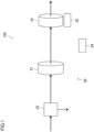
FIG. 1 is a schematic view showing an example configuration of an adsorption system according to an embodiment. -
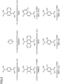
FIG. 2 shows examples of an organic ligand of a metal-organic framework applicable to an adsorbent of the adsorption system according to the embodiment. - An embodiment will be described with reference to the drawings. An adsorption system (100) according to this embodiment shown in
FIG. 1 includes an adsorption section (10) using an adsorbent that contains a metal-organic framework (hereinafter referred to as an "MOF"). The adsorption system (100) may be integral with an outdoor unit of an air conditioner, for example. The adsorption system (100) may be placed, for example, in an air passage for taking outdoor air and supplying the air to a room. A fan may be placed in the air passage, upstream or downstream of the adsorption section (10). InFIG. 1 , the arrows represent the flow of the air in the adsorption system (100). - The adsorption section (10) adsorbs a target substance (except water) in the air, such as carbon dioxide and a volatile organic compound (VOC). The adsorption section (10) adsorbs the target substance in the air flowing in from the upstream side and allows the air from which the target substance is removed or reduced to flow out to the downstream side. The adsorption section (10) may be in a disk shape, for example. The adsorption section (10) may be configured, for example, as a substrate having a honeycomb structure and a surface where an adsorbent is held. The adsorption section (10) may be configured to allow the air to pass therethrough in the thickness direction and cause the passing air to come into contact with the adsorbent. In the present disclosure, the "adsorbent" includes a material (what is called a sorbent) that adsorbs and absorbs a target substance.
- The substrate of the adsorption section (10) may be made from a material such as ceramic paper, glass fibers, organic compounds (for example, paper) whose main component is cellulose, metals, and resins. These materials have lower specific heat. If the adsorption section (10) is made of these materials, an "adsorption and desorption section" has a lower heat capacity.
- The MOF to be contained in the adsorbent of the adsorption section (10) can be selected as appropriate from various combinations of a metal ion and an organic ligand in accordance with the purpose of the adsorption system, such as the target substance to be adsorbed. The adsorbent of the adsorption section (10) may contain a plurality of types of MOFs or an MOF in combination with another adsorbent substance.
- In the adsorption section (10), the adsorbent may be regenerated as appropriate by utilizing a temperature change or a pressure change, for example, to avoid saturation of adsorption of the target substance by the adsorbent. The adsorbent may be regenerated as regular maintenance targeting the whole adsorption section (10), for example. Alternatively, the adsorption section (10) may be configured as a rotor, so that the adsorbent in a respective part of the adsorption section (10) is regenerated when the part comes to a predetermined regeneration region as the adsorption section (10) rotates.
- As shown in
FIG. 1 , the adsorption system (100) further includes a reduction section (20) configured to reduce the accumulation of moisture in the adsorption section (10). In this embodiment, the reduction section (20) includes a dehydration element (21), a heating element (22), a decrease element (23), and a control unit (24). - The dehydration element (21) is placed upstream of the adsorption section (10). The dehydration element (21) removes or reduces the moisture in the air flowing into the adsorption section (10). The dehydration element (21) may be a dehumidifier, for example. The dehydration element (21) may dehumidify the air by having the moisture in the air adsorbed on the adsorbent. The adsorbent may be silica or zeolite, for example. In the dehydration element (21), the adsorbent that has adsorbed moisture may be regenerated by heating, for example, to be used again for dehumidification. The dehydration element (21) may be configured as a rotor, so that the adsorbent in a respective part of the dehydration element (21) is regenerated when the part comes to a predetermined regeneration region as the dehydration element (21) rotates.
- The heating element (22) heats the adsorption section (10) to evaporate the moisture in the air that has flowed into the adsorption section (10). The evaporated moisture flows out to the downstream side of the adsorption section (10) along with the flow of the air. The heating element (22) may always heat the adsorption section (10) or may heat the adsorption section (10) regularly or upon satisfaction of predetermined conditions. The heating element (22) may be a heater, for example. The heating element (22) may be placed near the adsorption section (10) or integral with the adsorption section (10). In a case in which the adsorbent used in the adsorption section (10) is regenerated by changing a temperature (e.g., heating), the heating element (22) for evaporating the moisture may be used as the heating element for regenerating the adsorbent. In this case, the heating element (22) performs the temperature control for regenerating the adsorbent and the temperature control for evaporating the moisture in parallel.
- The decrease element (23) can decrease the flow rate of the air flowing into the adsorption section (10). The decrease element (23) may block the flow of the air into the adsorption section (10). The decrease element (23) may be a three-way valve, for example. The decrease element (23) is placed upstream of the adsorption section (10), for example, upstream of the dehydration element (21). The decrease element (23) may always decrease the air flow rate or may decrease the air flow rate regularly or upon satisfaction of predetermined conditions.
- The control unit (24) controls the operation of at least one selected from the group consisting of the dehydration element (21), the heating element (22), and the decrease element (23) in accordance with the humidity of the air flowing into the adsorption section (10), thereby controlling the operation for reducing the accumulation of the moisture in the adsorption section (10). For example, if the humidity of the air flowing into the adsorption section (10) exceeds a predetermined value, the control unit (24) causes the heating element (22) to heat the adsorption section (10) or causes the decrease element (23) to decrease the flow rate of the air flowing into the adsorption section (10). The humidity of the air flowing into the adsorption section (10) is detected, for example, by a sensor (not shown) arranged near the upstream side of the adsorption section (10). The control unit (24) can obtain the detected value. The control unit (24) may be comprised, for example, of a microcomputer (not shown) and a program for operating the microcomputer.
- As described above, the adsorption system (100) of this embodiment includes: an adsorption section (10) configured to adsorb a target substance except water; and a reduction section (20) configured to reduce accumulation of moisture in the adsorption section (10), wherein an adsorbent used in the adsorption section (10) contains a metal-organic framework (MOF). Thus, the accumulation of the moisture in the adsorption section (10) is reduced, thereby making it possible to reduce the degradation of the adsorption performance of the MOF due to the moisture. It is also possible to increase the efficiency in adsorbing the target substance by the MOF by removing the moisture trapped, instead of the target substance, by the MOF.
- According to the adsorption system (100) of this embodiment, it is possible to reduce the degradation of the adsorption performance of the MOF due to the moisture even if a zinc-containing MOF, less resistant to water, is used as the adsorbent.
FIG. 2 shows examples of the organic ligand forming the zinc-containing MOF. Combining the organic ligand shown inFIG. 2 and zinc (Zn) can provide MOFs, such as Zn(NDC)(DABCO)0.5 (abbr. DMOF-N), Zn(BDC)0.5(TNMDC)0.5(DABCO)0.5 (abbr. DMOF-TM1), Zn(TMBDC)(DABCO)o.s (abbr. DMOF-TM2), Zn(ADC)(DABCO)0.5 (abbr. DMOF-A), Zn(BDC-NO2)(DABCO)0.5 (abbr. DMOF-N), Zn(BDC-(Cl)2)(DABCO)0.5 (abbr. DMOF-Cl2), Zn(BDC-Br)(DABCO)0.5 (abbr. DMOF-Br), and Zn(BDC-OH)(DABCO)0.5 (abbr. DMOF-OH). These zinc-containing MOFs exhibit excellent adsorption performance for carbon dioxide under atmospheric pressure. These zinc-containing MOFs can desorb carbon dioxide as the pressure is lowered, and hence can be used as an adsorbent that can be regenerated by a pressure change. However, if exposed to water, most of these zinc-containing MOFs will lose the porous structure and exhibit lower adsorption performance for carbon dioxide. On the other hand, according to the adsorption system (100) of this embodiment, the accumulation of the moisture in the adsorption section (10) is reduced, thereby making it possible to reduce the degradation of adsorption performance for carbon dioxide even when these zinc-containing MOFs are used as the adsorbent. - In the adsorption system (100) of this embodiment, the reduction section (20) may include a dehydration element (21) placed upstream of the adsorption section (10). The dehydration element (21) in this configuration can reduce the moisture in the air flowing into the adsorption section (10). Accordingly, the accumulation of the moisture in the adsorption section (10) is reduced.
- In the adsorption system (100) of this embodiment, the reduction section (20) may include a heating element (22) configured to heat the adsorption section (10). The heating element (22) in this configuration can evaporate the moisture in the air that has flowed into the adsorption section (10) and release the evaporated moisture to the downstream side of the adsorption section (10). Accordingly, the accumulation of the moisture in the adsorption section (10) is reduced.
- In the adsorption system (100) according to this embodiment, the reduction section (20) may include a decrease element (23) configured to decrease a flow rate of air flowing into the adsorption section (10). In this configuration, it is also possible to reduce the amount of the moisture in air flowing into the adsorption section (10) by decreasing the flow rate of the air flowing into the adsorption section (10). Accordingly, the accumulation of the moisture in the adsorption section (10) is reduced.
- In the adsorption system (100) of this embodiment, the reduction section (20) may perform a reduction operation of reducing the accumulation of the moisture in accordance with a humidity of air flowing into the adsorption section (10). In this configuration, the reduction section (20) can reduce the accumulation of the moisture efficiently in accordance with the humidity of the air, thereby making it possible to reduce the energy consumption of the heating element (22), for example.
- An example has been described above in the embodiment where carbon dioxide is the target substance to be adsorbed and desorbed. The target substance is however not limited thereto and may be an odor substance (e.g., sulfur or ammonia), for example.
- An example has been described above in the embodiment where the zinc-containing MOF is used as the adsorbent. The adsorbent is however not limited thereto and may be another type of MOF, such as an aluminum-containing MOF.
- In the embodiment described above, the dehydration element (21), the heating element (22), the decrease element (23), and the control unit (24) form the reduction section (20). Instead, for example, any one of the dehydration element (21), the heating element (22), and the decrease element (23), or any one of them in combination with the control unit (24), may form the reduction section (20). Alternatively, for example, any two of the dehydration element (21), the heating element (22), and the decrease element (23), or any two of them in combination with the control unit (24), may form the reduction section (20).
- The decrease element (23) is placed upstream of the dehydration element (21) in the embodiment described above. Instead, the decrease element (23) may be placed downstream of the dehydration element (21). In another example, a first air passage with the dehydration element (21) and a second air passage without the dehydration element (21) may be provided upstream of the adsorption section (10): If the humidity of the air flowing into the adsorption section (10) is higher than or equal to a predetermined value, the air flows into the adsorption section (10) via the first air passage; and if the humidity is lower than the predetermined value, the air flows into the adsorption section (10) via the second air passage.
- The substrate of the adsorption section (10) has a honeycomb structure in the embodiment described above. However, the substrate is not limited thereto and may be in a mesh shape or a filter shape. Even in these shapes, the adsorption section (10) is configured to allow air to pass therethrough. The adsorption section (10) is in the disk shape, but not limited thereto, and may be in a polygonal plate shape, for example.
- While the embodiment has been described above, it will be understood that various changes in form and details can be made without departing from the spirit and scope of the claims. The above embodiment may be combined or replaced as appropriate as long as the functions of the target of the present disclosure are not impaired.
- As described above, the present disclosure is useful as an adsorption system.
-
- 100
- Adsorption System
- 10
- Adsorption Section
- 20
- Reduction Section
- 21
- Dehydration Element
- 22
- Heating Element
- 23
- Decrease Element
- 24
- Control Unit
Claims (6)
- An adsorption system comprising:an adsorption section (10) configured to adsorb a target substance except water; anda reduction section (20) configured to reduce accumulation of moisture in the adsorption section (10), whereinan adsorbent used in the adsorption section (10) contains a metal-organic framework.
- The adsorption system of claim 1, wherein
the reduction section (20) includes a dehydration element (21) placed upstream of the adsorption section (10). - The adsorption system of claim 1 or 2, wherein
the reduction section (20) includes a heating element (22) configured to heat the adsorption section (10). - The adsorption system of any one of claims 1 to 3, wherein
the reduction section (20) includes a decrease element (23) configured to decrease a flow rate of air flowing into the adsorption section (10). - The adsorption system of any one of claims 1 to 4, wherein
the reduction section (20) performs a reduction operation of reducing the accumulation of the moisture in accordance with a humidity of air flowing into the adsorption section (10). - The adsorption system of any one of claims 1 to 5, wherein
the metal-organic framework contains zinc.
Applications Claiming Priority (2)
| Application Number | Priority Date | Filing Date | Title |
|---|---|---|---|
| JP2021041305A JP7277801B2 (en) | 2021-03-15 | 2021-03-15 | adsorption system |
| PCT/JP2022/004722 WO2022196181A1 (en) | 2021-03-15 | 2022-02-07 | Adsorption system |
Publications (2)
| Publication Number | Publication Date |
|---|---|
| EP4275782A1 true EP4275782A1 (en) | 2023-11-15 |
| EP4275782A4 EP4275782A4 (en) | 2024-10-16 |
Family
ID=83322243
Family Applications (1)
| Application Number | Title | Priority Date | Filing Date |
|---|---|---|---|
| EP22770940.9A Pending EP4275782A4 (en) | 2021-03-15 | 2022-02-07 | ADSORPTION SYSTEM |
Country Status (5)
| Country | Link |
|---|---|
| US (1) | US11951436B2 (en) |
| EP (1) | EP4275782A4 (en) |
| JP (1) | JP7277801B2 (en) |
| CN (1) | CN116847919B (en) |
| WO (1) | WO2022196181A1 (en) |
Families Citing this family (8)
| Publication number | Priority date | Publication date | Assignee | Title |
|---|---|---|---|---|
| JP7677307B2 (en) * | 2022-11-02 | 2025-05-15 | トヨタ自動車株式会社 | Adsorption system and adsorption method |
| EP4454751A1 (en) * | 2023-04-24 | 2024-10-30 | Calistair SAS | Adsorption system for fluids and gas depollution apparatus containing the same and its use |
| JP7827010B2 (en) * | 2023-05-26 | 2026-03-10 | トヨタ自動車株式会社 | Adsorption system and adsorption method |
| WO2025180620A1 (en) * | 2024-02-28 | 2025-09-04 | Robert Bosch Gmbh | Air management system comprising a direct air capture module and method of controlling the air management system |
| WO2025180614A1 (en) * | 2024-02-28 | 2025-09-04 | Robert Bosch Gmbh | Direct air capture module for use with a heating, ventilation and/or air conditioning system |
| WO2025180615A1 (en) * | 2024-02-28 | 2025-09-04 | Robert Bosch Gmbh | Method and system for controlling a direct air capture system for use with a heating, ventilation and/or air conditioning system |
| JP7778834B2 (en) * | 2024-03-25 | 2025-12-02 | 本田技研工業株式会社 | Carbon dioxide capture equipment |
| WO2025238613A2 (en) * | 2024-05-16 | 2025-11-20 | Nardi Compressori Srl | Apparatus for separating o2 and n2 and compressing and drying them and its method of use |
Family Cites Families (14)
| Publication number | Priority date | Publication date | Assignee | Title |
|---|---|---|---|---|
| US4264340A (en) * | 1979-02-28 | 1981-04-28 | Air Products And Chemicals, Inc. | Vacuum swing adsorption for air fractionation |
| US4934148A (en) * | 1989-05-12 | 1990-06-19 | Union Carbide Corporation | Dry, high purity nitrogen production process and system |
| US8501150B2 (en) | 2006-04-18 | 2013-08-06 | Basf Aktiengesellschaft | Metal oxides from metal-organic framework materials |
| CN101421183A (en) | 2006-04-18 | 2009-04-29 | 巴斯夫欧洲公司 | Metal oxide prepared by metal organic backbone material |
| FR2933313B1 (en) | 2008-07-03 | 2011-07-22 | Air Liquide | TREATMENT OF WET GAS CONTAINING DUST |
| JP5067507B2 (en) * | 2009-05-22 | 2012-11-07 | ダイキン工業株式会社 | Fluid processing apparatus and fluid |
| KR101106658B1 (en) | 2011-07-12 | 2012-01-18 | 대한전기공업 주식회사 | Efficient Condensation Dehumidifier |
| CN102423600B (en) * | 2011-10-28 | 2014-04-02 | 中国石油大学(北京) | A method for improving adsorption and separation efficiency of mixed gas containing CO2 |
| JP2014113539A (en) | 2012-12-10 | 2014-06-26 | Hitachi Ltd | Co2 capture material, and co2 separation device |
| CA2904546C (en) * | 2013-03-11 | 2021-12-07 | Uti Limited Partnership | Metal organic framework, production and use thereof |
| JP6575050B2 (en) * | 2014-08-12 | 2019-09-18 | 株式会社Ihi | Carbon dioxide recovery method and recovery apparatus |
| JP6383467B1 (en) * | 2017-07-19 | 2018-08-29 | 株式会社西部技研 | Dehumidifying air conditioner |
| JP6603299B2 (en) | 2017-12-25 | 2019-11-06 | 株式会社西部技研 | Ventilation air conditioner |
| BR112021018433A2 (en) * | 2019-03-19 | 2021-11-23 | Basf Corp | Filter units, system, electric automobile ventilation and automobile ventilation systems and method of using a filter unit |
-
2021
- 2021-03-15 JP JP2021041305A patent/JP7277801B2/en active Active
-
2022
- 2022-02-07 WO PCT/JP2022/004722 patent/WO2022196181A1/en not_active Ceased
- 2022-02-07 CN CN202280013339.8A patent/CN116847919B/en active Active
- 2022-02-07 EP EP22770940.9A patent/EP4275782A4/en active Pending
-
2023
- 2023-08-11 US US18/233,195 patent/US11951436B2/en active Active
Also Published As
| Publication number | Publication date |
|---|---|
| WO2022196181A1 (en) | 2022-09-22 |
| JP7277801B2 (en) | 2023-05-19 |
| EP4275782A4 (en) | 2024-10-16 |
| JP2022141134A (en) | 2022-09-29 |
| US20230381709A1 (en) | 2023-11-30 |
| CN116847919B (en) | 2024-11-12 |
| CN116847919A (en) | 2023-10-03 |
| US11951436B2 (en) | 2024-04-09 |
Similar Documents
| Publication | Publication Date | Title |
|---|---|---|
| EP4275782A1 (en) | Adsorption system | |
| CN109282374B (en) | Dehumidifying air conditioner | |
| Kong et al. | Research needs targeting direct air capture of carbon dioxide: Material & process performance characteristics under realistic environmental conditions | |
| US10837660B2 (en) | Ventilating air conditioning apparatus | |
| CN102143792B (en) | Solid state materials and methods for removing CO2 from gas streams | |
| US10343105B2 (en) | Air cleaning system | |
| US11592195B2 (en) | Dehumidifying air handling unit and desiccant wheel therefor | |
| KR20180083403A (en) | Heat recovery adsorber as building ventilation system | |
| AU2017208389A1 (en) | Desiccant based honeycomb chemical filter and method of manufacture thereof | |
| WO2017114687A1 (en) | A component for an air filter | |
| CN104955179A (en) | PTC (positive temperature coefficient) heater and electric appliance comprising same | |
| JP4830348B2 (en) | Humidification device and humidification method | |
| JP2011089665A (en) | Humidity control device | |
| JP2006061758A (en) | Carbon dioxide remover | |
| WO2015094124A1 (en) | A membrane and hybrid air dehumidification system using same for improved moisture removal | |
| JP4972987B2 (en) | Gas processing equipment | |
| KR102179325B1 (en) | Energy saving air dryer and preparing method of dry air using the same | |
| KR101168096B1 (en) | Refrigerator System for Semiconductor Process | |
| JP2025043448A (en) | Carbon dioxide adsorption device | |
| JP2006142121A (en) | Air treatment equipment | |
| JP2008238077A (en) | Dehumidifying element, method for manufacturing dehumidifying element, and dehumidifier | |
| JP7728582B2 (en) | Dehumidification and heating systems for horticultural facilities | |
| KR20260017532A (en) | Hydrogen sulfide removal and dehumidifying combined type desiccant dehumidifier and desiccant dehumidification method | |
| KR20190084134A (en) | Deodorizing device | |
| KR20230109187A (en) | Crystals containing copper-based coordination polymer particles and alumina, and method for preparing the same |
Legal Events
| Date | Code | Title | Description |
|---|---|---|---|
| STAA | Information on the status of an ep patent application or granted ep patent |
Free format text: STATUS: THE INTERNATIONAL PUBLICATION HAS BEEN MADE |
|
| PUAI | Public reference made under article 153(3) epc to a published international application that has entered the european phase |
Free format text: ORIGINAL CODE: 0009012 |
|
| STAA | Information on the status of an ep patent application or granted ep patent |
Free format text: STATUS: REQUEST FOR EXAMINATION WAS MADE |
|
| 17P | Request for examination filed |
Effective date: 20230809 |
|
| AK | Designated contracting states |
Kind code of ref document: A1 Designated state(s): AL AT BE BG CH CY CZ DE DK EE ES FI FR GB GR HR HU IE IS IT LI LT LU LV MC MK MT NL NO PL PT RO RS SE SI SK SM TR |
|
| DAV | Request for validation of the european patent (deleted) | ||
| DAX | Request for extension of the european patent (deleted) | ||
| A4 | Supplementary search report drawn up and despatched |
Effective date: 20240913 |
|
| RIC1 | Information provided on ipc code assigned before grant |
Ipc: B01J 20/22 20060101ALI20240909BHEP Ipc: A61L 9/014 20060101ALI20240909BHEP Ipc: B01D 53/26 20060101ALI20240909BHEP Ipc: B01D 53/06 20060101ALI20240909BHEP Ipc: B01D 53/04 20060101AFI20240909BHEP |
|
| P01 | Opt-out of the competence of the unified patent court (upc) registered |
Free format text: CASE NUMBER: APP_1025/2025 Effective date: 20250108 |
|
| STAA | Information on the status of an ep patent application or granted ep patent |
Free format text: STATUS: EXAMINATION IS IN PROGRESS |
|
| 17Q | First examination report despatched |
Effective date: 20250625 |
|
| GRAP | Despatch of communication of intention to grant a patent |
Free format text: ORIGINAL CODE: EPIDOSNIGR1 |
|
| STAA | Information on the status of an ep patent application or granted ep patent |
Free format text: STATUS: GRANT OF PATENT IS INTENDED |
|
| INTG | Intention to grant announced |
Effective date: 20260129 |
|
| GRAS | Grant fee paid |
Free format text: ORIGINAL CODE: EPIDOSNIGR3 |
|
| GRAA | (expected) grant |
Free format text: ORIGINAL CODE: 0009210 |
|
| STAA | Information on the status of an ep patent application or granted ep patent |
Free format text: STATUS: THE PATENT HAS BEEN GRANTED |