EP4275727A2 - Devices for delivering powdered agents - Google Patents
Devices for delivering powdered agents Download PDFInfo
- Publication number
- EP4275727A2 EP4275727A2 EP23195364.7A EP23195364A EP4275727A2 EP 4275727 A2 EP4275727 A2 EP 4275727A2 EP 23195364 A EP23195364 A EP 23195364A EP 4275727 A2 EP4275727 A2 EP 4275727A2
- Authority
- EP
- European Patent Office
- Prior art keywords
- agent
- fluid
- valve
- configuration
- source
- Prior art date
- Legal status (The legal status is an assumption and is not a legal conclusion. Google has not performed a legal analysis and makes no representation as to the accuracy of the status listed.)
- Granted
Links
Images




Classifications
-
- A—HUMAN NECESSITIES
- A61—MEDICAL OR VETERINARY SCIENCE; HYGIENE
- A61M—DEVICES FOR INTRODUCING MEDIA INTO, OR ONTO, THE BODY; DEVICES FOR TRANSDUCING BODY MEDIA OR FOR TAKING MEDIA FROM THE BODY; DEVICES FOR PRODUCING OR ENDING SLEEP OR STUPOR
- A61M31/00—Devices for introducing or retaining media, e.g. remedies, in cavities of the body
-
- A—HUMAN NECESSITIES
- A61—MEDICAL OR VETERINARY SCIENCE; HYGIENE
- A61M—DEVICES FOR INTRODUCING MEDIA INTO, OR ONTO, THE BODY; DEVICES FOR TRANSDUCING BODY MEDIA OR FOR TAKING MEDIA FROM THE BODY; DEVICES FOR PRODUCING OR ENDING SLEEP OR STUPOR
- A61M11/00—Sprayers or atomisers specially adapted for therapeutic purposes
- A61M11/02—Sprayers or atomisers specially adapted for therapeutic purposes operated by air or other gas pressure applied to the liquid or other product to be sprayed or atomised
-
- A—HUMAN NECESSITIES
- A61—MEDICAL OR VETERINARY SCIENCE; HYGIENE
- A61B—DIAGNOSIS; SURGERY; IDENTIFICATION
- A61B17/00—Surgical instruments, devices or methods
- A61B17/00491—Surgical glue applicators
-
- A—HUMAN NECESSITIES
- A61—MEDICAL OR VETERINARY SCIENCE; HYGIENE
- A61B—DIAGNOSIS; SURGERY; IDENTIFICATION
- A61B17/00—Surgical instruments, devices or methods
- A61B17/00234—Surgical instruments, devices or methods for minimally invasive surgery
-
- A—HUMAN NECESSITIES
- A61—MEDICAL OR VETERINARY SCIENCE; HYGIENE
- A61M—DEVICES FOR INTRODUCING MEDIA INTO, OR ONTO, THE BODY; DEVICES FOR TRANSDUCING BODY MEDIA OR FOR TAKING MEDIA FROM THE BODY; DEVICES FOR PRODUCING OR ENDING SLEEP OR STUPOR
- A61M13/00—Insufflators for therapeutic or disinfectant purposes, i.e. devices for blowing a gas, powder or vapour into the body
-
- A—HUMAN NECESSITIES
- A61—MEDICAL OR VETERINARY SCIENCE; HYGIENE
- A61M—DEVICES FOR INTRODUCING MEDIA INTO, OR ONTO, THE BODY; DEVICES FOR TRANSDUCING BODY MEDIA OR FOR TAKING MEDIA FROM THE BODY; DEVICES FOR PRODUCING OR ENDING SLEEP OR STUPOR
- A61M31/00—Devices for introducing or retaining media, e.g. remedies, in cavities of the body
- A61M31/007—Injectors for solid bodies, e.g. suppositories
-
- A—HUMAN NECESSITIES
- A61—MEDICAL OR VETERINARY SCIENCE; HYGIENE
- A61B—DIAGNOSIS; SURGERY; IDENTIFICATION
- A61B17/00—Surgical instruments, devices or methods
- A61B17/00234—Surgical instruments, devices or methods for minimally invasive surgery
- A61B2017/00292—Surgical instruments, devices or methods for minimally invasive surgery mounted on or guided by flexible, e.g. catheter-like, means
- A61B2017/00296—Surgical instruments, devices or methods for minimally invasive surgery mounted on or guided by flexible, e.g. catheter-like, means mounted on an endoscope
-
- A—HUMAN NECESSITIES
- A61—MEDICAL OR VETERINARY SCIENCE; HYGIENE
- A61B—DIAGNOSIS; SURGERY; IDENTIFICATION
- A61B17/00—Surgical instruments, devices or methods
- A61B2017/00367—Details of actuation of instruments, e.g. relations between pushing buttons, or the like, and activation of the tool, working tip, or the like
-
- A—HUMAN NECESSITIES
- A61—MEDICAL OR VETERINARY SCIENCE; HYGIENE
- A61B—DIAGNOSIS; SURGERY; IDENTIFICATION
- A61B17/00—Surgical instruments, devices or methods
- A61B17/00491—Surgical glue applicators
- A61B2017/00495—Surgical glue applicators for two-component glue
-
- A—HUMAN NECESSITIES
- A61—MEDICAL OR VETERINARY SCIENCE; HYGIENE
- A61M—DEVICES FOR INTRODUCING MEDIA INTO, OR ONTO, THE BODY; DEVICES FOR TRANSDUCING BODY MEDIA OR FOR TAKING MEDIA FROM THE BODY; DEVICES FOR PRODUCING OR ENDING SLEEP OR STUPOR
- A61M39/00—Tubes, tube connectors, tube couplings, valves, access sites or the like, specially adapted for medical use
- A61M39/22—Valves or arrangement of valves
- A61M39/24—Check- or non-return valves
- A61M2039/2473—Valve comprising a non-deformable, movable element, e.g. ball-valve, valve with movable stopper or reciprocating element
-
- A—HUMAN NECESSITIES
- A61—MEDICAL OR VETERINARY SCIENCE; HYGIENE
- A61M—DEVICES FOR INTRODUCING MEDIA INTO, OR ONTO, THE BODY; DEVICES FOR TRANSDUCING BODY MEDIA OR FOR TAKING MEDIA FROM THE BODY; DEVICES FOR PRODUCING OR ENDING SLEEP OR STUPOR
- A61M39/00—Tubes, tube connectors, tube couplings, valves, access sites or the like, specially adapted for medical use
- A61M39/22—Valves or arrangement of valves
- A61M39/24—Check- or non-return valves
- A61M2039/2473—Valve comprising a non-deformable, movable element, e.g. ball-valve, valve with movable stopper or reciprocating element
- A61M2039/2486—Guided stem, e.g. reciprocating stopper
-
- A—HUMAN NECESSITIES
- A61—MEDICAL OR VETERINARY SCIENCE; HYGIENE
- A61M—DEVICES FOR INTRODUCING MEDIA INTO, OR ONTO, THE BODY; DEVICES FOR TRANSDUCING BODY MEDIA OR FOR TAKING MEDIA FROM THE BODY; DEVICES FOR PRODUCING OR ENDING SLEEP OR STUPOR
- A61M2202/00—Special media to be introduced, removed or treated
- A61M2202/0007—Special media to be introduced, removed or treated introduced into the body
-
- A—HUMAN NECESSITIES
- A61—MEDICAL OR VETERINARY SCIENCE; HYGIENE
- A61M—DEVICES FOR INTRODUCING MEDIA INTO, OR ONTO, THE BODY; DEVICES FOR TRANSDUCING BODY MEDIA OR FOR TAKING MEDIA FROM THE BODY; DEVICES FOR PRODUCING OR ENDING SLEEP OR STUPOR
- A61M2202/00—Special media to be introduced, removed or treated
- A61M2202/06—Solids
- A61M2202/064—Powder
-
- A—HUMAN NECESSITIES
- A61—MEDICAL OR VETERINARY SCIENCE; HYGIENE
- A61M—DEVICES FOR INTRODUCING MEDIA INTO, OR ONTO, THE BODY; DEVICES FOR TRANSDUCING BODY MEDIA OR FOR TAKING MEDIA FROM THE BODY; DEVICES FOR PRODUCING OR ENDING SLEEP OR STUPOR
- A61M2205/00—General characteristics of the apparatus
- A61M2205/04—General characteristics of the apparatus implanted
-
- A—HUMAN NECESSITIES
- A61—MEDICAL OR VETERINARY SCIENCE; HYGIENE
- A61M—DEVICES FOR INTRODUCING MEDIA INTO, OR ONTO, THE BODY; DEVICES FOR TRANSDUCING BODY MEDIA OR FOR TAKING MEDIA FROM THE BODY; DEVICES FOR PRODUCING OR ENDING SLEEP OR STUPOR
- A61M2205/00—General characteristics of the apparatus
- A61M2205/33—Controlling, regulating or measuring
-
- A—HUMAN NECESSITIES
- A61—MEDICAL OR VETERINARY SCIENCE; HYGIENE
- A61M—DEVICES FOR INTRODUCING MEDIA INTO, OR ONTO, THE BODY; DEVICES FOR TRANSDUCING BODY MEDIA OR FOR TAKING MEDIA FROM THE BODY; DEVICES FOR PRODUCING OR ENDING SLEEP OR STUPOR
- A61M2205/00—General characteristics of the apparatus
- A61M2205/33—Controlling, regulating or measuring
- A61M2205/3331—Pressure; Flow
-
- A—HUMAN NECESSITIES
- A61—MEDICAL OR VETERINARY SCIENCE; HYGIENE
- A61M—DEVICES FOR INTRODUCING MEDIA INTO, OR ONTO, THE BODY; DEVICES FOR TRANSDUCING BODY MEDIA OR FOR TAKING MEDIA FROM THE BODY; DEVICES FOR PRODUCING OR ENDING SLEEP OR STUPOR
- A61M2210/00—Anatomical parts of the body
- A61M2210/10—Trunk
- A61M2210/1042—Alimentary tract
Definitions
- aspects of the disclosure relate generally to devices and methods for delivering agents. More specifically, aspects of the disclosure relate to devices for delivery of powdered agents, such as hemostatic agents.
- an endoscopic medical procedure may require hemostasis of bleeding tissue within the gastrointestinal tract, for example in the esophagus, stomach, or intestines.
- a user inserts a sheath of an endoscope into a body lumen of a patient.
- the user utilizes a handle of the endoscope to control the endoscope during the procedure.
- Tools are passed through a working channel of the endoscope via, for example, a port in the handle, to deliver treatment at the procedure site near a distal end of the endoscope.
- the procedure site is remote from the operator.
- a hemostatic agent may be delivered by a device inserted into the working channel of the endoscope.
- Agent delivery may be achieved through mechanical systems, for example. Such systems, however, may require numerous steps or actuations to achieve delivery, may not achieve a desired rate of agent delivery or a desired dosage of agent, may result in the agent clogging portions of the delivery device, may result in inconsistent dosing of agent, or may not result in the agent reaching the treatment site deep within the GI tract.
- the current disclosure may solve one or more of these issues or other issues in the art.
- a device for delivering an agent may comprise a source of agent; a mixing chamber for receiving fluid and the agent; an outlet in fluid communication with the mixing chamber to deliver the fluid and the agent; and an actuator configured to (1) deliver a first flow of the fluid substantially free from the agent through the outlet; (2) after delivering the first flow, deliver a second flow of the fluid and the agent through the outlet; and (3) after delivering the second flow, deliver a third flow of the fluid substantially free from the agent through the outlet.
- the actuator may transition from a first configuration to a second configuration.
- the source of agent may not be in fluid communication with the mixing chamber.
- the source of agent may not be in fluid communication with the mixing chamber.
- the actuator may include a valve defining an opening. In the first configuration, the opening may not be in fluid communication with the source of agent. In the second configuration, the opening may not be in fluid communication with the source of agent.
- the valve may include a first portion and a second portion. A spring may connect the first portion to the second portion. The valve may be able to transition from the first configuration to the second configuration only when a flow of the fluid is flowing through the mixing chamber.
- the actuator may include a body pivotable via at least one of a piston or a wire.
- the actuator may include a first rigid member and a second rigid member.
- the first rigid member may be pivotably coupled to the second rigid member.
- the second rigid member may include a trigger.
- the actuator may include a rotatable member having at least one blade extending from the rotatable member.
- the actuator may further include a gear.
- the actuator may include a first actuator for controlling a flow of the agent from the source of agent and a second actuator for controlling a flow of the fluid.
- the first actuator and the second actuator may be configured to be independently activated.
- the first actuator may be activated only if the second actuator is activated.
- the actuator may include a spring and a button valve.
- the actuator may include a first portion; a second portion defining an opening; and a spring extending from the first portion to the second portion.
- the opening In the first configuration and the third configuration, the opening may not be in fluid communication with the source of agent.
- the opening In the second configuration, the opening may not be in fluid communication with the source of agent.
- the agent may include a powder.
- the actuator may define an opening. In the first configuration and the third configuration, the opening may not be in fluid communication with the source of agent. In the second configuration, the opening may be in fluid communication with the source of agent such that the powder can pass through the opening.
- a device for delivering an agent may comprise: a source of fluid; a source of powderized agent; a mixing chamber for receiving the fluid and the powderized agent; and an actuator configured to transition from a first configuration to a second configuration.
- the source of agent may not be in fluid communication with the mixing chamber and a first flow of fluid substantially free from agent is received in the mixing chamber.
- the source of agent may be in fluid communication with the mixing chamber and the powderized agent and a second flow of fluid are received in the mixing chamber.
- the actuator may be further configured to transition from the second configuration to the first configuration after transitioning form the first configuration to the second configuration.
- a method of delivering an agent may comprise: activating an actuator to cause: delivering a first flow of fluid, wherein the fluid is substantially free from a agent; after delivering the first flow, delivering a second flow of the fluid combined with the agent; and after delivering the second flow, delivering a third flow of fluid, wherein the fluid is substantially free from a agent.
- the agent may include a hemostatic agent.
- the fluid may be a pressurized fluid.
- an opening of the actuator may not be in fluid communication with a source of the agent.
- an opening of the actuator may be in fluid communication with the source of the agent.
- exemplary is used in the sense of “example,” rather than “ideal.”
- distal refers to a direction away from an operator
- proximal refers to a direction toward an operator.
- approximately or like terms (e.g., “substantially"), includes values +/- 10% of a stated value.
- a dual-stage actuation mechanism may be used to deliver an agent (e.g., a powdered agent) from a delivery system to a site of a medical procedure.
- the actuation mechanism may function to, upon activation, first deliver a flow of fluid, without the agent, through the delivery system and to the site. Then, a combined flow of the fluid and the agent may be delivered. Following delivery of a desired amount of the agent, the fluid may again be delivered without the agent. Delivery of fluid alone, before and after delivery of the agent, may facilitate flushing of components of the delivery system and may prevent clogging of the delivery system.
- FIG. 1A shows a delivery system 10, which may be a powder delivery system.
- Delivery system 10 may include a body 12.
- Body 12 may have a variety of features, to be discussed in further detail herein. The features described herein may be used alone or in combination and are not mutually exclusive. Like reference numbers and/or terminology are used to denote similar structures, when possible.
- FIG. 1B shows a cross-section of an exemplary body 12, which may be a component of delivery system 10.
- Body 12 may include or may be configured to receive an enclosure 14 (or other source) storing an agent 16.
- Enclosure 14 may be screwed onto body 12 for providing agent 16 to body 12, or a lid/store of agent 16 may be screwed onto enclosure 14 for supplying agent 16 to enclosure 14.
- Agent 16 may be, for example, a powdered agent, such as a hemostatic agent.
- Agent 16 may alternatively be another type of agent or form of agent (e.g., a liquid or gel agent) and may have any desired function.
- Enclosure 14 may be removably attached to other components of delivery system 10, including components of body 12.
- Body 12 may have an agent inlet 18 in fluid communication with enclosure 14 for receiving agent 16 from enclosure 14.
- Body 12 may include a fluid inlet 20 for receiving fluid, such as pressurized fluid, from a source 24 (e.g., a disposable canister, a tank, a supply line, etc.).
- a source 24 e.g., a disposable canister, a tank, a supply line, etc.
- Body 12 may include a nozzle 22, shown separately in FIG. 1C .
- Nozzle 22 may include a nozzle chamber 25, which may be in fluid communication with source 24.
- Nozzle chamber 25 may terminate in an opening 26.
- a diameter of nozzle opening 26 may be between 0.015 and 0.030 inches (e.g., 0.020 inches).
- Opening 26 may be positioned approximately along a longitudinal axis of agent inlet 18.
- Opening 26 may be positioned behind, slightly behind, slightly in front of, or directly in front of agent inlet 18.
- Opening 26 may be in fluid communication with a mixing body 27 defining a mixing chamber 28 for combining agent 16 with fluid from source 24.
- Nozzle 22 may connect with mixing body 27 of body 12 via any suitable fastening method (e.g., nuts, bolts, being formed of a continuous material with mixing body 27, etc.)
- An O-ring 29a may sit in an annular seat 29b of nozzle 22 so as to provide a seal between nozzle 22 and mixing body 27.
- Mixing body 27 may connect with enclosure 14 via any suitable fastening method (such as screwing onto mixing body 27, as shown) and may also include seals 31, 32 to provide seals between enclosure 14 and mixing body 27 or other portions of body 12.
- a combination of agent 16 and fluid may be delivered from outlet 34 of body 12.
- Outlet 34 may be in fluid communication with a catheter 36 (see FIG. 1A ) or other component for delivering the combination of agent 16 and fluid to a desired location within a body lumen of a patient.
- Mixing chamber 28 may be in fluid communication with outlet 34 and mixing chamber 28 and/or outlet 34 may be configured to allow for fluid connection with catheter 36.
- a diameter/width of outlet 34 may be the same as or approximately the same as a diameter/width of catheter 36 or an internal lumen of catheter 36.
- a lack of edges formed between mixing body 27 (including mixing chamber 28 and outlet 34) may reduce clogging of agent passing into catheter 36.
- a catheter may have an inner diameter of 0.080 inches, 0.050 inches, or 0.030 inches, for example, and mixing chamber 28, outlet 34, and or/mixing body 27 may be dimensioned for compatibility with those sizes of catheter.
- Delivery system 10 may include an actuation mechanism 30 for controlling a release of agent 16 and/or fluid via outlet 34.
- actuation mechanism 30 may include a trigger, button, slider, knob, lever, or other suitable mechanism.
- Actuation mechanism may cause agent 14 and/or fluid to enter mixing chamber 28, where agent 14 and fluid may be combined.
- delivery system 10 may include more than one actuation mechanism 30.
- multiple actuation mechanisms 30 may be used to separately control a flow of fluid through fluid inlet 20 and a flow of agent from enclosure 14 through agent inlet 18.
- FIGS. 2A-2C show cross-sectional views of an exemplary body, which may be a component of delivery system 10.
- Body 112 may include an agent inlet 118, which may be in fluid communication with enclosure 14 storing an agent 16.
- Agent inlet 118 may be appropriately sized so as to allow passage of agent 16 therethrough.
- Agent inlet 118 may have approximately the same size as opening 152, described below.
- Agent inlet 118 may be an opening formed in body 112.
- Agent inlet 118 may be a portion of enclosure 14, particularly where enclosure 14 is not detachable from body 112.
- enclosure 14 may include an opening formed therein, which may be in fluid communication with agent inlet 118.
- Body 112 also may include a fluid inlet 120 for receiving fluid from source 24 (see FIG. 1C ).
- Body 112 may also include a valve 138 for controlling flow of fluid through fluid inlet 120 and agent 16 through agent inlet 118.
- Valve 138 may be operatively connected to actuation mechanism 30 (see FIG. 1A ).
- Valve 138 may include a first portion 140.
- First portion 140 may have a first seal 142 and a second seal 144 received thereon.
- First seal 142 and/or second seal 144 may be, for example, O-ring seals.
- First portion 140 may also include a neck portion 148, between first seal 142 and second seal 144.
- Neck portion 148 may have a smaller cross-sectional diameter than other portions of first portion 140 (e.g., those receiving first seal 144 and second seal 146).
- Valve 138 may also include a second portion 150.
- Second portion 150 may define an opening 152. Opening 152 may extend through an entire thickness of second portion 150 in a direction parallel to longitudinal axis of agent inlet 118 (but not through an entire width of second portion 150).
- Second portion 150 may have a third seal 154, fourth seal 156, and fifth seal 158 received thereupon.
- Third seal 154 may be on a first side of opening 152, more proximate to first portion 140.
- Fourth seal 156 may be on a second, opposite side of opening 152.
- Fifth seal 158 also may be on the second side of opening 152.
- First portion 140 may be closer to fourth seal 156 than to fifth seal 158.
- a first spring 162 may extend between and connect first portion 140 and second portion 150.
- First spring 162 may be fixedly connected to an end 164 of first portion 140 and to an end 166 of second portion 150.
- First portion 140 may taper to first end 164, which may have a smaller cross-sectional diameter than other portions of first portion 140.
- Second portion 150 may taper to first end 166, which may have a smaller cross-sectional diameter than other portions of second portion 150.
- First end 166 may be an end of second portion 150 that is closest to third seal 154.
- a second spring 168 may extend from a second end 170 of second portion 150.
- Second end 170 may be an end of second portion 150 that is closest to fifth seal 158.
- First spring 162 may have a smaller spring constant than second spring 168 (i.e., first spring 162 may be a weaker spring than second spring 168). An equivalent force on first spring 162 and second spring 168 may cause first spring 162 to compress more than second spring 168.
- Valve 138 may be received within a cavity 200 of body 112.
- Cavity 200 may be defined by surface(s) 202.
- First cavity 200 may have a first opening 204, which is at one end of cavity 200.
- Cavity 200 may have a second opening 206, which is in fluid communication with fluid inlet 120 and source 24.
- a third opening 208 of cavity 200 may be in fluid communication with a fluid nozzle chamber 210.
- a fourth opening 212 of cavity 200 may be in fluid communication with a mixing chamber 214, which may have any of the features of mixing chamber 30.
- Fourth opening 212 may be aligned or approximately aligned with agent inlet 118 so as to be in selective fluid communication with agent inlet 118.
- Second spring 168 may contact surface 202 at an end 205 of cavity 200 that is opposite from the end of cavity 200 having first opening 204.
- Seals 142, 144, 154, 156, 158 may have dimensions and measurements on a durometer such that they form seals with surface(s) 202 of cavity 200. Seals 142, 144, 154, 156, 158 may also permit sliding movement of valve 138 within cavity 200.
- FIG. 2A shows body 112 in a first configuration, in which agent 16 is not permitted to flow into cavity 200 via agent inlet 118, and fluid is not permitted to flow into cavity 200 via fluid inlet 120.
- Fourth seal 156 and fifth seal 158 may be positioned on either side of agent inlet 118 so that agent 16 may not pass between seals 156, 158 and surface(s) 202, thus preventing flow of agent 16.
- First seal 142 and second seal 144 may be positioned on either side of fluid inlet 120. Seals 142, 144, may prevent movement of fluid from fluid inlet 120 between seals 142, 144 and surface(s) 202.
- springs 162, 164 may be in relaxed, uncompressed states.
- FIG. 2B shows body 112 in a second configuration, in which fluid is permitted to flow into cavity 200 via fluid inlet 120.
- first portion 140 of valve138 may translate within cavity 200, in a first direction toward end 205 of cavity 200.
- Actuation mechanism 30 may be a separate component, or a surface of valve 138 may serve as an actuation mechanism and may receive a force from a user's hand.
- First portion 140 may exert a force first against spring 162, causing first spring 162 to compress. Because first spring 162 is weaker than second spring 168 and/or because second portion 150 may not move until first spring 162 is compressed a selected amount, second portion 150 may not immediately move along with first portion 140.
- an entirety of second seal 144 may not be in contact with surface(s) 202.
- second seal 144 may be aligned with a portion of third opening 208.
- fluid from fluid inlet 120 may pass between first portion 140 and surface(s) 202 (e.g., along neck portion 148).
- the fluid may then pass through third opening 208 into fluid nozzle chamber 210.
- the fluid may then pass through a fluid nozzle opening 220, into mixing chamber 214.
- the fluid may then exit through outlet 134.
- second portion 150 may remain in the same position or in approximately the same position as in the first configuration ( FIG. 2A ). Therefore, for the reasons discussed above, agent 16 may not be permitted to flow into cavity 200 via agent inlet 118. As a result, only the fluid from source 24 may exit outlet 134.
- second portion 150 may begin to move in the first direction (to the left in the Figures), after first spring 162 has been sufficiently compressed, when the force is sufficient to compress second spring 168.
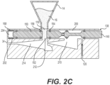
- Valve 138 may be thusly transitioned from the second configuration ( FIG. 2B ) to a third configuration of FIG. 2C .
- third seal 154 and fourth seal 156 may be disposed on opposite sides of agent inlet 118, and opening 152 of second portion 150 may be aligned with agent inlet 118 so as to be in fluid communication with agent inlet 118. Therefore, agent 16 may be permitted to pass into opening 152, via agent inlet 118. Agent may be unable to pass between third and fourth seals 154, 156 and surface(s) 202, maintaining agent 16 in a desired location so that it will pass through opening 152.
- first portion 140 may remain in the same position or in approximately the same position as in the second configuration ( FIG. 2B ). Therefore, fluid from source 24 may continue to flow as described above, with respect to FIG. 2B .
- Second spring 168 and/or actuation mechanism 30 may be configured so that, after second spring 168 is compressed by a specified amount, neither of first portion 140 or second portion 150 may move further in the first direction, to maintain the third configuration of FIG. 2C . In the third configuration, second spring 168 may be fully compressed or may be only partially compressed.
- agent 16 may pass through fourth opening 212, into mixing chamber 214. There, agent 16 may combine with fluid from source 24. The combined agent 16 and fluid from fluid source 24 may then pass through outlet 134, to be delivered to a desired location.
- a restoring force of second spring 168 may return valve 138 to the second configuration, in which fluid from source 24 is delivered, but agent 16 is not delivered. Then, a restoring force of first spring 162 may return valve 138 to the first configuration, in which neither of fluid from source 24 nor agent 16 is delivered.
- first and second springs 162, 164 may be compressed in the second configuration so as to align seals 142, 144, 154, 156, 158 as described above to allow delivery of only fluid from source 24.
- first spring 162 may experience further compression (first spring 162 may not be fully compressed in the second configuration).
- valve 138 in between the first and second configurations and in between the second and third configurations,
- configurations may exist in which a portion of agent inlet 118 is covered and a portion of agent inlet 118 is aligned with opening 152 so that opening 152 is in fluid communication with agent inlet 118.
- a relatively smaller amount of agent 16 may be permitted to pass through opening 152, compared with the third configuration ( FIG. 2B ).
- an increasing amount of agent inlet 118 may align with opening 152, allowing an increasing amount of agent 16 to pass into opening 152.
- Body 112 may facilitate delivery of fluid from source 24 that is free from or substantially free from agent 16 through outlet 134 before delivery of agent 16 and after delivery of agent 16. This delivery of fluid from source 24 that is free from or substantially free from agent 16 may flush system 10, reducing or eliminating clogging.
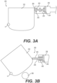
- FIGS. 3A and 3B show an exemplary metering mechanism 250, which may be used as a portion of delivery system 10.
- FIGS. 3A and 3B both show views with enclosure 14 removed, looking in a direction toward agent inlet 18 and body 12 (i.e. enclosure 14 would be coming out of the top of the page of FIGS. 3A and 3B ).
- metering mechanism 250 may include a door 252, which may pivot about a fixed pivot point A, and which may be a knife-edge door that has a very thin thickness in a direction parallel to a longitudinal axis of agent inlet 18.
- door 252 may have a shape that includes any combination of straight and rounded sides.
- door 252 may have three straight sides and one rounded side. Pivot point A may be located between one of the straight sides and the rounded side.
- Metering mechanism 250 may also include a piston 254.
- Piston 254 may be disposed partially within a chamber 256, and a stem 258 of piston 254 may extend through an opening 260 in a wall of chamber 256.
- a spring 262 may also be disposed within chamber 256.
- Stem 258 of piston 254 may extend along a central axis of spring 258.
- Chamber 256 may be fluidly connected to a source of fluid, such as source 24.
- a source of fluid such as source 24.
- chamber 256 When the fluid 24 enters chamber 256, chamber 256 may be pressurized, and the fluid may exert a force on a head 264 of piston 254, in a first direction toward opening 260. The force from the fluid may cause piston 254 to move in the first direction.
- a seal (not shown) may be disposed between chamber 256 and one or both of stem 258 and head 264, so that the fluid may not exit chamber 256.
- piston 254 may compress spring 262, generating a restorative force in a second direction, opposite the first direction.
- a movement of piston 254 in the first direction may stop when any of the following occurs (1) head 264 presses against surfaces of chamber 256; (2) a restorative force of spring 262 is equal to a force of the fluid on piston 254; and/or (c) spring 262 is fully compressed.
- FIG. 3A shows a first configuration of metering mechanism 250, shown in FIG. 3A , spring 262 may be in a relaxed state (such as when no fluid is supplied to chamber 256). Door 252 may be in a first position.
- FIG. 3B shows a second configuration of metering mechanism 250, in which spring 262 is compressed, and piston 254 has moved in the first direction (due to fluid supplied to chamber 256). Door 252 may be in a second position.
- Piston 254 and door 252 may be configured such that, when fluid is supplied to chamber 256, as piston 254 moves in the first direction, piston 254 exerts a force on door 252 in the first direction.
- the force of piston 254 may cause door 252 to rotate about pivot point A.
- door 252 may expose an opening 266, which may be in fluid communication with a chamber (not shown) of body 12.
- opening 266 may be exposed due to rotation of door 252.
- door 252 may continue to rotate, and more of opening 266 may be exposed.
- opening 266 When piston 254 is fully extended ( FIG. 3B ), an entirety of opening 266 may be exposed. In the first position of door 252 ( FIG. 3A ), door 252 covers opening 266, so that opening 266 does not communicate with enclosure 14, and no agent 16 can pass into opening 266.
- actuation mechanism 30 When actuation mechanism 30 is no longer activated, pressure may be released from chamber 256 (via, e.g., a release valve, which is not shown).
- Spring 262 may urge head 264 of piston 254 in the second direction, away from the opening 260, due to the restoring force of spring 262.
- piston 254 may no longer exert a force on door 252.
- the restoring force of spring 262 may cause piston 254 to return to the first configuration ( FIG. 3A ).
- Door 252 may also be biased to return to the first configuration ( FIG. 3A ).
- door 252 may be spring biased at, e.g., at pivot point A.
- actuation mechanism 30 when actuation mechanism 30 is activated, such activation may cause fluid to pass through fluid inlet 20 and out of outlet 34. Meanwhile, as described above, actuation mechanism 30 may begin to expose opening 266. A portion of opening 266 may not immediately be exposed due to a delay in pressurizing chamber 256, or a delay in exposing opening 266 once chamber 256 is pressurized. Additionally or alternatively, a size of a portion of opening 266 that is exposed may initially be sized such that agent 16 does not flow through opening 260, or only a small amount of agent flows through opening 260. Thus, initially after actuation mechanism is activated, only fluid from source 24 may initially flow from outlet 34, without any agent 16.
- fluid may continue to be delivered via outlet 34, after actuation mechanism 30 begins or finishes transitioning from the second configuration ( FIG. 3B ) to the first configuration ( FIG. 3A ).
- actuation mechanism 30 may be configured so that chamber 256 is depressurized before fluid stops passing through fluid inlet 20. Opening 266 may be covered partially or entirely by door 252, while fluid continues to pass through fluid inlet 20.
- Metering mechanism 250 may facilitate delivery of fluid from source 24 that is free from or substantially free from agent 16 through outlet 34 before delivery of agent 16 and after delivery of agent 16. This delivery of fluid from source 24 that is free from or substantially free from agent 16 may flush system 10, reducing or eliminating clogging.
- FIGS. 4A-4B show cross-sectional views of an exemplary body 312 for use with delivery system 10.
- Body 312 may include an agent inlet 318, which may be in fluid communication with enclosure 14 storing an agent 16.
- Body 312 also may include a fluid inlet 320 for receiving fluid from source 24 (see FIG. 1B ).
- Body 312 may also include a metering mechanism 330 for controlling flow of fluid through fluid inlet 320 and agent 16 through agent inlet 318.
- Metering mechanism 330 may have any of the features of metering mechanism 250.
- Metering mechanism 330 may include a door 332, which may have any of the properties of door 252.
- Door 332 may be configured to rotate about a hinge B.
- Door 332 may also be operatively connected to a wire 333.
- a portion of door 332 that is on an opposite side of door 332 from hinge B may be operatively connected to wire 333.
- a first end 336 of wire 333 may be attached to a ridge 338 extending from an edge of door 332 in a direction parallel to a longitudinal axis of agent inlet 318.
- a second end 340 of wire 333 may be operatively connected to a valve 350.
- Valve 350 may be operatively connected to an actuation mechanism 30 or may include a surface which serves as an actuation mechanism 30 by receiving contact from a finger of a user.
- Valve 350 may be received within a fluid channel 352, which may be in fluid connection with fluid inlet 320 and a fluid nozzle chamber 322.
- a longitudinal axis of valve 350 may be approximately perpendicular to a longitudinal axis of fluid channel 352.
- Valve 350 may also be received within a valve channel 354, which may have a longitudinal axis that is approximately parallel to a longitudinal axis of valve 350.
- Valve 350 may include first, second and third seals 356, 358, 360, which may be, for example, O-ring seals. Seals 356, 358, 360 may prevent air from entering valve channel 354 from fluid channel 352.
- Valve 350 may be dimensioned and formed of a material such that, in the configuration of FIG. 4A , valve 350 blocks fluid channel 352, such that fluid from fluid inlet 320 may not pass valve 350 to enter fluid nozzle chamber 322.
- valve channel 354 may have a larger cross-sectional area than a cross-sectional area of fluid channel 352, and valve 350 may occupy an entirety or approximately an entirety of valve 354.
- Door 332 may be biased such that, when no force is exerted on door 332 from wire 333 and door 332 is in a relaxed configuration, door 332 is approximately perpendicular or otherwise transverse to a central longitudinal axis of agent inlet 318, such that agent 16 may not pass door 332 to pass through fluid inlet 320.
- door 332 may be spring-biased at pivot point B.
- FIG. 4A shows a first configuration of body 312, in which door 332 is in a relaxed configuration, effectively closing agent inlet 318 so that agent inlet 318 is not in communication with a mixing chamber 372.
- Valve 350 may be movable in first and second directions, perpendicular to a longitudinal axis of fluid channel 352 and parallel to a longitudinal axis of valve channel 354. As valve 350 moves in the first direction, narrowed portions 351 of valve 350 may move such that they are disposed within fluid channel 352, and fluid may move past valve 350. The narrowed portions may have a cross-sectional area that is smaller than that of fluid channel 352, so that fluid may pass valve 350. Therefore, movement of valve 350 in the first direction may activate flow of fluid from fluid inlet 320 into fluid nozzle chamber 322.
- Movement of valve 350 in the first direction may compress a spring 362.
- spring 362 When spring 362 is in a neutral, relaxed configuration, door 332 may also in its relaxed configuration (the configuration to which door 332 is biased), so that agent 16 may not flow past door 332 into agent inlet 318.
- valve 350 may move second end 340 of wire 333 in the first direction (to the right in FIGS> 4A-4B).
- first end 336 of wire 333 may move in the first direction.
- first end 336 of wire 333 may move in another direction such that a force from first end 336 of wire 333 causes door 332 to pivot about hinge B.
- Wire 333 may be routed over a pulley 364, to accommodate space for other components of body 312 and/or delivery system 10.
- first end 336 of wire 333 When first end 336 of wire 333 moves in the first direction, it may exert a force on ridge 338 in the first direction, which may cause door 332 to pivot such that an angle between door 332 and fluid inlet 320 increases (gets closer to 180 degrees) as door 332 pivots. As door 332 pivots, agent 16 may begin to flow past agent inlet 318 and door 332. Valve 350 and/or door 332 may stop moving when any one or more of the following occurs: door 332 contacts a surface defining agent inlet 318 or other structure of body 312, spring 362 reaches a maximum compression against a surface of valve channel 354, or a surface of valve 350 reaches a stop (not shown).
- FIG. 4B shows body 312 in a second configuration, in which door 332 is fully open.
- door 332 may gradually pull away from agent inlet 318, yet fluid may flow through a fluid nozzle chamber 322, into a mixing chamber 372, and out of outlet 334, before any agent 16 or an appreciable amount of agent 16 is able to enter mixing chamber 372. Opening of door 332 may occur after valve 350 permits flow of fluid from fluid inlet 320. Once door 332 is opened a sufficient amount upon further activation of actuation mechanism 30, agent 16 may enter mixing chamber 372 to be mixed with fluid and to be delivered out of outlet 334. After actuation mechanism 30 is deactivated, door 332 may begin to return to its unbiased position.
- Closing of agent inlet 318 may allow a flow of fluid out of outlet 334 without any or an appreciable amount of agent 16 entering a mixing chamber 372.
- a flow of fluid without agent 16, or appreciable amounts of agent 16, before and after a flow of fluid combined with agent 16 may lessen clogging of portions of system 10.
- body 312 may facilitate a flow of fluid without agent 16 before and after a flow of fluid combined with agent 16.
- properties of spring 362 and/or slack in wire 333 may delay opening of door 332, and/or actuation mechanism 30 may be configured to permit a flow of fluid before movement of valve 350 in the first direction commences and after valve 350 returns to its unbiased configuration following delivery of agent 16 ( FIG. 3A ).
- Body 312 may facilitate delivery of fluid from source 24 that is free from or substantially free from agent 16 through outlet 334 before delivery of agent 16 and after delivery of agent 16. This delivery of fluid from source 24 that is free from or substantially free from agent 16 may flush system 10, reducing or eliminating clogging.
- FIGS. 5A-5B show cross-sectional views of an exemplary body 412, which may be a portion of delivery system 10.
- Body 412 may include a metering mechanism 430.
- Metering mechanism 430 may include a slider 432 (a first rigid member), which may be made from any suitable material (e.g., plastic, metal, composites, polymers, etc.)
- Slider 432 may be made of rigid or substantially rigid material. Slider 432 may include an opening 436 formed therein. Slider 432 may be configured to translate or slide in first and second directions relative to a remainder of body 412.
- a longitudinal axis of slider 432 may be transverse (e.g., perpendicular) to a longitudinal axis of an agent inlet 418, and movement of slider 432 may be axial along the longitudinal axis of slider 432.
- Slider 432 may be pivotably coupled to an arm 438 (a second rigid member) via, e.g., a hinge 437. Slider 432 may be received within a channel (not shown) or otherwise constrained so that slider 432 may only translate along the first and second directions (i.e., axial movement). Hinge 437 may be similarly translatable within that channel. Arm 438 may be rotatable about an axis C, extending into and out of the page as shown in FIGS. 5A and 5B . Axis C is also shown in FIG. 5C relative to arm 438. Arm 438 may include a trigger 440 at one end of arm 438.
- Trigger 440 may be contacted by a user in order to rotate arm 438 about axis C and thereby translate slider 432.
- Arm 438 may have an approximately rectangular shape, as shown in FIG. 5C .
- An opening 439 in arm 438 may receive components of body 412 (e.g., a fluid nozzle chamber 462).
- a top bar 438a of arm 438 may connect to slider 432 at hinge 437.
- trigger 440 may compress a spring 450.
- Spring 450 may be operatively coupled to a button valve 460.
- Button valve 460 may be operative to allow and disallow flow from source 24 through a fluid inlet 420.
- FIG. 5A A first configuration of metering mechanism 430 is shown in FIG. 5A .
- spring 450 may be in a relaxed, uncompressed state that biases trigger 440 to the configuration of FIG. 5A .
- Opening 436 of slider 432 may be offset from agent inlet 418, such that agent 16 may not pass through opening 436 and agent inlet 418.
- an operator may depress trigger 440, which may be an example of actuation mechanism 30.
- a greater force may be required to compress spring 450 than to open button valve 460 to allow force of fluid from source 24 through fluid inlet 420.
- a compression of trigger 440 required to depress a button 461 of button valve 460 and open button valve 460 may be approximately 0.075 inches.
- spring 450 may partially compress to open button valve 460, and further compression of spring 450 may be required in order to translate opening 436 sufficiently that it is in communication with agent inlet 418.
- a further compression of trigger 440 required to compress spring 450 may be approximately 0.33 inches.
- a total throw of trigger 404 may be approximately 0.504 inches.
- a force depressing trigger 440 may initially translate spring 450 to open button valve 460 and to activate flow of fluid from source 24 through fluid inlet 420. Fluid may flow into fluid inlet 420, into a fluid nozzle chamber 462. Fluid may pass through an opening 462 of fluid nozzle chamber 462, into mixing chamber 464. Fluid may then exit via outlet 34. In the first configuration, agent 16 may not be delivered via outlet 434, since opening 436 is not aligned with agent inlet 418.
- spring 450 may be compressed (or may be further compressed). Compression of spring 450 will enable arm 438 to rotate about axis C (or further about axis C). Rotation of arm 438 may, in turn, cause slider 432 to translate in the first direction (to the left in the Figures), aligning opening 436 with agent inlet 418, transitioning metering mechanism 430 to the second configuration of FIG. 5B .
- fluid from source 24 may continue to flow as described above, with respect to the first configuration ( FIG. 5A ). Because opening 436 is aligned with agent inlet 418 and in fluid communication with agent inlet 418, agent 16 may also pass through opening 436 and agent inlet 418. Agent 16 may then enter mixing chamber 464, where it may mix with fluid from source 24. The combined agent 16 and fluid may then be delivered via outlet 434.
- Trigger 440 may include an opening 470, which may be, for example, an elliptical shape. Opening 470 may receive components (not shown) that couple trigger 440 to spring 450, while allowing for necessary movement of trigger 440 relative to stationary spring 450 and button valve 460.
- spring 450 may first decompress, causing slider 432 to return to a configuration that misaligns opening 436 and agent inlet 418. Because opening 436 may be offset from agent inlet 418, agent 16 may not pass through agent inlet 418. However, because button valve 460 may remain open, fluid may continue to flow from source 24 through fluid inlet 20 for a time, until button valve 460 then closes.
- Body 412 may facilitate delivery of fluid from source 24 that is free from or substantially free from agent 16 through outlet 434 before delivery of agent 16 and after delivery of agent 16. This delivery of fluid from source 24 that is free from or substantially free from agent 16 may flush system 10, reducing or eliminating clogging.
- FIGS. 6A-6B show another example body 512, which may be a component of system 10.
- Body 512 may have any of the features of body 112 of FIGS. 2A-2C .
- a fluid inlet 520 of body 512 may be in direct fluid communication with a fluid nozzle chamber 610, without requiring fluid to first pass through a cavity 600.
- a valve 538 may include only one stem portion 550, which may have any of the properties of second portion 150.
- Stem portion 550 may include an opening 552 (like opening 152) and may be sealingly slidable within cavity 600.
- Flow to fluid inlet 520 may be controlled via a valve 522, which may be, for example, a button valve.
- Valve 522 may actuate independently of valve 538. Thus, valve 522 may be opened, allowing a flow of fluid to enter fluid inlet 520 and exit outlet 534. Meanwhile, valve 538 may separately be actuated to permit flow of agent 16 through agent inlet 518.
- FIG. 6A shows a first configuration, in which valve 522 is closed and valve 538 is in a first configuration, in which opening 552 is not aligned (not in fluid communication) with an agent inlet 518.
- fluid may not pass through fluid inlet 20, and agent may not pass through agent inlet 518, so that neither fluid nor agent is delivered via outlet 534.
- FIG. 6B shows a second configuration, in which valve 522 is open and valve 538 is in a second configuration, in which opening 552 is aligned with agent inlet 518 so as to be in fluid communication with agent inlet 518.
- fluid may pass through fluid inlet 520, and agent 16 may pass through agent inlet 518, so that fluid and agent 16 may combine in mixing chamber 514 and be delivered from outlet 534.
- Body 512 may be configured so that valve 538 may be actuated to the second configuration only when valve 522 is open. Thus, agent 16 may not enter mixing chamber 514 if fluid from source 24 is not also delivered to mixing chamber 514.
- a user may actuate a first actuation mechanism 530 (which may be, for example, a button of valve 522). Fluid may flow through body 512 and out of outlet 534.
- a user may then actuate a second actuation mechanism (not shown) to transition valve 538 to the second configuration to deliver a combination of agent 16 and fluid.
- a user may not be able to release first actuation mechanism 530 without first releasing the second actuation mechanism.
- valve 538 may transition back to the first configuration of valve 538 due to a restorative force of a spring 568, which may have any of the properties of second spring 168. A user may then release first actuation mechanism 530 to close valve 522 and stop flow of fluid through fluid inlet 520.
- Body 512 may facilitate delivery of fluid from source 24 that is free from or substantially free from agent 16 through outlet 534 before delivery of agent 16 and after delivery of agent 16. This delivery of fluid from source 24 that is free from or substantially free from agent 16 may flush system 10, reducing or eliminating clogging.
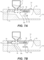
- FIGS. 7A-7D show aspects of a body 712 that may form a part of delivery system 10.
- FIGS. 7A-7B show cross-sectional views of body 712 in first and second configurations, respectively, and
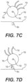
- FIGS. 7C-7D show aspects of a turbine 750 that may be a component of body 712.
- a body 712 may have an agent inlet 718, a fluid inlet 720, and an outlet 734, in fluid connection with one another via a chamber 752.
- Turbine 750 may be disposed in chamber 752.
- Turbine 750 may include a plurality of blades 754 extending radially outward from a central body 756 (see FIGS. 7C-7D ). Although three blades 754 are shown, it will be appreciated that other numbers of blades 754 may be utilized.
- Blades 754 may have any suitable shape, including the shape shown.
- Blades 754 may be formed from any suitable material, including rigid or flexible material, such as metals or plastics.
- Turbine 750 may also have a stop mechanism 758, which may extend radially outward from central body 756. Stop mechanism 758 may have any suitable shape, including a wedge shape, which may be a curved wedge shape. Stop mechanism 758 may be made from any suitable material, including rigid materials.
- Turbine 750 may be fixedly connected to an axle 760 and may be rotatable about axle 760.
- Axle 760 may extend from central body 756 and may also be fixedly connected to a round gear 762, which may include teeth. Via axle 760, turbine 750 and gear 762 may rotate together, in unison.
- Gear 762 may be formed of any suitable material and may include any suitable number of teeth. Turbine 750 and gear 762 may have any suitable size.
- Gear 762 may interact with a linear rack 764.
- Linear rack 764 may be movable relative to gear 762, along a direction transverse to a longitudinal axis of agent inlet 718 (e.g., perpendicular to agent inlet 718, left/right in the Figures).
- Rack 764 may include an opening 764a formed therein.
- a spring 770 may extend from an end of rack 764 furthest from gear 762, and a first end of spring 770 may be fixed relative to rack 764.
- a second end of spring 770 may be fixed relative to a surface 772 defining chamber 752.
- actuation mechanism 30 ( FIG. 1 ) may not be activated, and fluid may not flow from source 24 to fluid inlet 720.
- Turbine 750, gear 762, and rack 764 may each be stationary.
- Spring 770 may be in a relaxed state.
- Rack 764 may be positioned so that opening 764a is not aligned with (not in fluid communication with) agent inlet 718.
- Rack 764 may include seals 765 to prevent agent from moving between an outer surface of rack 764 and a surface of chamber 752.
- agent 16 may not enter chamber 752 because opening 764a is not aligned with (not in fluid communication with) agent inlet 718.
- fluid inlet 720 When an actuation mechanism ( FIG. 1 ) is activated, flow from source 24 to fluid inlet 720 may be permitted. Fluid from fluid inlet 720 may interact with blades 754 to cause turbine 750 to rotate. Rotation of turbine 750 may cause corresponding rotation of gear 762. Rotation of gear 762 may cause rack 764 to translate in a first direction (to the left in the Figures), such that opening 764a moves closer to agent inlet 718.
- Spring 770 may be compressed as rack 764 translates, because a force from fluid on turbine 750 may overcome a restorative force of spring 770. As shown in FIG. 7B , in a second configuration of body 712, opening 764a may be aligned with (in fluid communication with) agent inlet 718.
- agent 16 may be permitted to flow through opening 764a and into chamber 752.
- agent 16 may mix with the fluid from source 24 and then exit through outlet 734.
- opening 764a is aligned with (in fluid communication with) agent inlet 718, only fluid from source 24 may flow through chamber 752 and exit outlet 734.
- Activation of actuation mechanism 30 may cause, either immediately or following a delay, a tab 780 to extend from a surface 772 of body 712.
- Tab 780 may extend in a direction perpendicular to axle 760.
- FIG. 7C shows turbine 750 and tab 780 prior to extension of tab 780 (e.g., prior to activation of actuation mechanism 30).
- FIG. 7D shows turbine 750 and tab 780 after tab 780 has been extended from surface 772.
- Tab 780 may interact with stop mechanism 758 to prevent further rotation of turbine 750 after stop mechanism 758 contacts tab 780.
- Tab 780 and stop mechanism 758 may stop gear 762 from continuing to rotate and thereby stop rack 764 from translating past a desired position, where opening 764a aligns with agent inlet 718.
- a flow of fluid through fluid inlet 720 may be eliminated or reduced, thereby eliminating or reducing a force on blades 754.
- a restorative force of spring 770 may overcome a force of fluid (if any) on turbine 750, causing rack 764 to translate in a second direction, opposite the first direction.
- Rack 764 may, in turn, cause rotation of gear 762, which may cause rotation of turbine 750, in a direction opposite to a direction of rotation while translating from the first configuration to the second configuration.
- Tab 780 may also retract. Opening 764a may no longer be aligned with (in fluid communication with) agent inlet 718, so agent 16 may no longer flow through agent inlet 718.
- fluid may continue to exit outlet 734, after a flow of agent 16 has ceased.
- body 712 may include a purge line, which requires actuation by another mechanism (e.g., a button).
- actuation mechanism 30 may have three positions. In a first position of actuation mechanism 30, no flow of fluid through fluid inlet 720 may occur. In a second position, fluid may be permitted to flow, but tab 780 or another component may interact with rack 764 to stop movement of rack 764 before opening 764a aligns with agent inlet 718, thereby preventing flow of agent 16.
- tab 780 or another component may be retracted/deactivated to permit rotation of turbine 750 and permit flow of agent 16 while fluid flows through fluid inlet 720.
- gear ratios between gear 762 and linear rack 764, a length of rack 764, and a strength of spring 770 may be chosen such that, when actuation mechanism 30 is activated, a known duration and/or amount of fluid from fluid inlet 720 may flow prior to alignment of opening 764a and agent inlet 718, providing a flow of fluid without agent 16. Following alignment of opening 764a and agent inlet 718, agent 16 may flow via agent inlet 718.
- actuation mechanism 30 may release actuation mechanism 30 and reactivate actuation mechanism 30.
- the user may only activate actuation mechanism for an amount of time such that fluid flows but agent does not flow (because opening 764a and agent inlet 718 do not align).
- Body 712 may facilitate delivery of fluid from source 24 through outlet 734 before delivery of agent 16 and after delivery of agent 16. This delivery of fluid from source 24 may flush system 10, reducing or eliminating clogging.
Landscapes
- Health & Medical Sciences (AREA)
- Life Sciences & Earth Sciences (AREA)
- General Health & Medical Sciences (AREA)
- Public Health (AREA)
- Heart & Thoracic Surgery (AREA)
- Biomedical Technology (AREA)
- Veterinary Medicine (AREA)
- Animal Behavior & Ethology (AREA)
- Engineering & Computer Science (AREA)
- Surgery (AREA)
- Anesthesiology (AREA)
- Hematology (AREA)
- Nuclear Medicine, Radiotherapy & Molecular Imaging (AREA)
- Medical Informatics (AREA)
- Molecular Biology (AREA)
- Infusion, Injection, And Reservoir Apparatuses (AREA)
- Nozzles (AREA)
Abstract

Description
- This application claims the benefit of priority to
U.S. Provisional Patent Application No. 62/942,898, filed December 3, 2019 - Various aspects of the disclosure relate generally to devices and methods for delivering agents. More specifically, aspects of the disclosure relate to devices for delivery of powdered agents, such as hemostatic agents.
- In certain medical procedures, it may be necessary to stop or minimize bleeding internal to the body. For example, an endoscopic medical procedure may require hemostasis of bleeding tissue within the gastrointestinal tract, for example in the esophagus, stomach, or intestines.
- During an endoscopic procedure, a user inserts a sheath of an endoscope into a body lumen of a patient. The user utilizes a handle of the endoscope to control the endoscope during the procedure. Tools are passed through a working channel of the endoscope via, for example, a port in the handle, to deliver treatment at the procedure site near a distal end of the endoscope. The procedure site is remote from the operator.
- To achieve hemostasis at the remote site, a hemostatic agent may be delivered by a device inserted into the working channel of the endoscope. Agent delivery may be achieved through mechanical systems, for example. Such systems, however, may require numerous steps or actuations to achieve delivery, may not achieve a desired rate of agent delivery or a desired dosage of agent, may result in the agent clogging portions of the delivery device, may result in inconsistent dosing of agent, or may not result in the agent reaching the treatment site deep within the GI tract. The current disclosure may solve one or more of these issues or other issues in the art.
- Each of the aspects disclosed herein may include one or more of the features described in connection with any of the other disclosed aspects.
- In an example, a device for delivering an agent may comprise a source of agent; a mixing chamber for receiving fluid and the agent; an outlet in fluid communication with the mixing chamber to deliver the fluid and the agent; and an actuator configured to (1) deliver a first flow of the fluid substantially free from the agent through the outlet; (2) after delivering the first flow, deliver a second flow of the fluid and the agent through the outlet; and (3) after delivering the second flow, deliver a third flow of the fluid substantially free from the agent through the outlet.
- Any of the devices disclosed herein may include any of the following features. The actuator may transition from a first configuration to a second configuration. In the first configuration, the source of agent may not be in fluid communication with the mixing chamber. In the second configuration, the source of agent may not be in fluid communication with the mixing chamber. The actuator may include a valve defining an opening. In the first configuration, the opening may not be in fluid communication with the source of agent. In the second configuration, the opening may not be in fluid communication with the source of agent. The valve may include a first portion and a second portion. A spring may connect the first portion to the second portion. The valve may be able to transition from the first configuration to the second configuration only when a flow of the fluid is flowing through the mixing chamber. The actuator may include a body pivotable via at least one of a piston or a wire. The actuator may include a first rigid member and a second rigid member. The first rigid member may be pivotably coupled to the second rigid member. The second rigid member may include a trigger. The actuator may include a rotatable member having at least one blade extending from the rotatable member. The actuator may further include a gear. The actuator may include a first actuator for controlling a flow of the agent from the source of agent and a second actuator for controlling a flow of the fluid. The first actuator and the second actuator may be configured to be independently activated. The first actuator may be activated only if the second actuator is activated. The actuator may include a spring and a button valve. The actuator may include a first portion; a second portion defining an opening; and a spring extending from the first portion to the second portion. In the first configuration and the third configuration, the opening may not be in fluid communication with the source of agent. In the second configuration, the opening may not be in fluid communication with the source of agent. The agent may include a powder. The actuator may define an opening. In the first configuration and the third configuration, the opening may not be in fluid communication with the source of agent. In the second configuration, the opening may be in fluid communication with the source of agent such that the powder can pass through the opening.
- In another example, a device for delivering an agent may comprise: a source of fluid; a source of powderized agent; a mixing chamber for receiving the fluid and the powderized agent; and an actuator configured to transition from a first configuration to a second configuration. In the first configuration, the source of agent may not be in fluid communication with the mixing chamber and a first flow of fluid substantially free from agent is received in the mixing chamber. In the second configuration, the source of agent may be in fluid communication with the mixing chamber and the powderized agent and a second flow of fluid are received in the mixing chamber.
- Any of the devices disclosed herein may have any of the following features. The actuator may be further configured to transition from the second configuration to the first configuration after transitioning form the first configuration to the second configuration.
- In an example, a method of delivering an agent may comprise: activating an actuator to cause: delivering a first flow of fluid, wherein the fluid is substantially free from a agent; after delivering the first flow, delivering a second flow of the fluid combined with the agent; and after delivering the second flow, delivering a third flow of fluid, wherein the fluid is substantially free from a agent.
- Any of the methods or devices disclosed herein may include any of the following features. The agent may include a hemostatic agent. The fluid may be a pressurized fluid. During the delivering of the first flow and the third flow, an opening of the actuator may not be in fluid communication with a source of the agent. During the delivering of the second flow, an opening of the actuator may be in fluid communication with the source of the agent.
- It may be understood that both the foregoing general description and the following . It may be understood that both the foregoing general description and the following detailed description are exemplary and explanatory only and are not restrictive of the invention, as claimed. As used herein, the terms "comprises," "comprising," or any other variation thereof, are intended to cover a non-exclusive inclusion, such that a process, method, article, or apparatus that comprises a list of elements does not include only those elements, but may include other elements not expressly listed or inherent to such process, method, article, or apparatus. The term "exemplary" is used in the sense of "example," rather than "ideal." The term "distal" refers to a direction away from an operator, and the term "proximal" refers to a direction toward an operator. The term "approximately," or like terms (e.g., "substantially"), includes values +/- 10% of a stated value.
- The accompanying drawings, which are incorporated in and constitute a part of this specification, illustrate aspects of the disclosure and together with the description, serve to explain the principles of the disclosure.
-
FIGS. 1A-1C show aspects of an exemplary delivery device. -
FIGS. 2A-7D show various example actuation mechanisms for use of a delivery device, including in the delivery device ofFIGS. 1A-1C . - A dual-stage actuation mechanism may be used to deliver an agent (e.g., a powdered agent) from a delivery system to a site of a medical procedure. The actuation mechanism may function to, upon activation, first deliver a flow of fluid, without the agent, through the delivery system and to the site. Then, a combined flow of the fluid and the agent may be delivered. Following delivery of a desired amount of the agent, the fluid may again be delivered without the agent. Delivery of fluid alone, before and after delivery of the agent, may facilitate flushing of components of the delivery system and may prevent clogging of the delivery system.
-
FIG. 1A shows adelivery system 10, which may be a powder delivery system.Delivery system 10 may include abody 12.Body 12 may have a variety of features, to be discussed in further detail herein. The features described herein may be used alone or in combination and are not mutually exclusive. Like reference numbers and/or terminology are used to denote similar structures, when possible. -
FIG. 1B shows a cross-section of anexemplary body 12, which may be a component ofdelivery system 10.Body 12 may include or may be configured to receive an enclosure 14 (or other source) storing anagent 16.Enclosure 14 may be screwed ontobody 12 for providingagent 16 tobody 12, or a lid/store ofagent 16 may be screwed ontoenclosure 14 for supplyingagent 16 toenclosure 14.Agent 16 may be, for example, a powdered agent, such as a hemostatic agent.Agent 16 may alternatively be another type of agent or form of agent (e.g., a liquid or gel agent) and may have any desired function.Enclosure 14 may be removably attached to other components ofdelivery system 10, including components ofbody 12.Body 12 may have anagent inlet 18 in fluid communication withenclosure 14 for receivingagent 16 fromenclosure 14.Body 12 may include afluid inlet 20 for receiving fluid, such as pressurized fluid, from a source 24 (e.g., a disposable canister, a tank, a supply line, etc.). -
Body 12 may include anozzle 22, shown separately inFIG. 1C .Nozzle 22 may include anozzle chamber 25, which may be in fluid communication withsource 24.Nozzle chamber 25 may terminate in anopening 26. A diameter ofnozzle opening 26 may be between 0.015 and 0.030 inches (e.g., 0.020 inches).Opening 26 may be positioned approximately along a longitudinal axis ofagent inlet 18.Opening 26 may be positioned behind, slightly behind, slightly in front of, or directly in front ofagent inlet 18. -
Opening 26 may be in fluid communication with a mixingbody 27 defining a mixingchamber 28 for combiningagent 16 with fluid fromsource 24.Nozzle 22 may connect with mixingbody 27 ofbody 12 via any suitable fastening method (e.g., nuts, bolts, being formed of a continuous material with mixingbody 27, etc.) An O-ring 29a may sit in anannular seat 29b ofnozzle 22 so as to provide a seal betweennozzle 22 and mixingbody 27. Mixingbody 27 may connect withenclosure 14 via any suitable fastening method (such as screwing onto mixingbody 27, as shown) and may also includeseals 31, 32 to provide seals betweenenclosure 14 and mixingbody 27 or other portions ofbody 12. - A combination of
agent 16 and fluid may be delivered fromoutlet 34 ofbody 12.Outlet 34 may be in fluid communication with a catheter 36 (seeFIG. 1A ) or other component for delivering the combination ofagent 16 and fluid to a desired location within a body lumen of a patient. Mixingchamber 28 may be in fluid communication withoutlet 34 and mixingchamber 28 and/oroutlet 34 may be configured to allow for fluid connection with catheter 36. A diameter/width ofoutlet 34 may be the same as or approximately the same as a diameter/width of catheter 36 or an internal lumen of catheter 36. A lack of edges formed between mixing body 27 (including mixingchamber 28 and outlet 34) may reduce clogging of agent passing into catheter 36. A catheter may have an inner diameter of 0.080 inches, 0.050 inches, or 0.030 inches, for example, and mixingchamber 28,outlet 34, and or/mixingbody 27 may be dimensioned for compatibility with those sizes of catheter. -
Delivery system 10 may include anactuation mechanism 30 for controlling a release ofagent 16 and/or fluid viaoutlet 34. For example,actuation mechanism 30 may include a trigger, button, slider, knob, lever, or other suitable mechanism. Actuation mechanism may causeagent 14 and/or fluid to enter mixingchamber 28, whereagent 14 and fluid may be combined. As discussed below,delivery system 10 may include more than oneactuation mechanism 30. For example,multiple actuation mechanisms 30 may be used to separately control a flow of fluid throughfluid inlet 20 and a flow of agent fromenclosure 14 throughagent inlet 18. -
FIGS. 2A-2C show cross-sectional views of an exemplary body, which may be a component ofdelivery system 10.Body 112 may include anagent inlet 118, which may be in fluid communication withenclosure 14 storing anagent 16.Agent inlet 118 may be appropriately sized so as to allow passage ofagent 16 therethrough.Agent inlet 118 may have approximately the same size asopening 152, described below.Agent inlet 118 may be an opening formed inbody 112.Agent inlet 118 may be a portion ofenclosure 14, particularly whereenclosure 14 is not detachable frombody 112. Alternatively,enclosure 14 may include an opening formed therein, which may be in fluid communication withagent inlet 118.Body 112 also may include afluid inlet 120 for receiving fluid from source 24 (seeFIG. 1C ). The arrow inFIG. 2B shows the direction of fluid flow intoinlet 120.Body 112 may also include avalve 138 for controlling flow of fluid throughfluid inlet 120 andagent 16 throughagent inlet 118.Valve 138 may be operatively connected to actuation mechanism 30 (seeFIG. 1A ). -
Valve 138 may include afirst portion 140.First portion 140 may have afirst seal 142 and asecond seal 144 received thereon.First seal 142 and/orsecond seal 144 may be, for example, O-ring seals.First portion 140 may also include aneck portion 148, betweenfirst seal 142 andsecond seal 144.Neck portion 148 may have a smaller cross-sectional diameter than other portions of first portion 140 (e.g., those receivingfirst seal 144 and second seal 146). -
Valve 138 may also include asecond portion 150.Second portion 150 may define anopening 152. Opening 152 may extend through an entire thickness ofsecond portion 150 in a direction parallel to longitudinal axis of agent inlet 118 (but not through an entire width of second portion 150).Second portion 150 may have athird seal 154,fourth seal 156, andfifth seal 158 received thereupon.Third seal 154 may be on a first side ofopening 152, more proximate tofirst portion 140.Fourth seal 156 may be on a second, opposite side ofopening 152.Fifth seal 158 also may be on the second side ofopening 152.First portion 140 may be closer tofourth seal 156 than tofifth seal 158. - A
first spring 162 may extend between and connectfirst portion 140 andsecond portion 150.First spring 162 may be fixedly connected to anend 164 offirst portion 140 and to anend 166 ofsecond portion 150.First portion 140 may taper tofirst end 164, which may have a smaller cross-sectional diameter than other portions offirst portion 140.Second portion 150 may taper tofirst end 166, which may have a smaller cross-sectional diameter than other portions ofsecond portion 150.First end 166 may be an end ofsecond portion 150 that is closest tothird seal 154. Asecond spring 168 may extend from asecond end 170 ofsecond portion 150.Second end 170 may be an end ofsecond portion 150 that is closest tofifth seal 158.First spring 162 may have a smaller spring constant than second spring 168 (i.e.,first spring 162 may be a weaker spring than second spring 168). An equivalent force onfirst spring 162 andsecond spring 168 may causefirst spring 162 to compress more thansecond spring 168. -
Valve 138 may be received within acavity 200 ofbody 112.Cavity 200 may be defined by surface(s) 202.First cavity 200 may have afirst opening 204, which is at one end ofcavity 200.Cavity 200 may have asecond opening 206, which is in fluid communication withfluid inlet 120 andsource 24. Athird opening 208 ofcavity 200 may be in fluid communication with afluid nozzle chamber 210. Afourth opening 212 ofcavity 200 may be in fluid communication with a mixingchamber 214, which may have any of the features of mixingchamber 30.Fourth opening 212 may be aligned or approximately aligned withagent inlet 118 so as to be in selective fluid communication withagent inlet 118.Second spring 168 may contactsurface 202 at anend 205 ofcavity 200 that is opposite from the end ofcavity 200 havingfirst opening 204. -
Seals cavity 200.Seals valve 138 withincavity 200. -
FIG. 2A showsbody 112 in a first configuration, in whichagent 16 is not permitted to flow intocavity 200 viaagent inlet 118, and fluid is not permitted to flow intocavity 200 viafluid inlet 120.Fourth seal 156 andfifth seal 158 may be positioned on either side ofagent inlet 118 so thatagent 16 may not pass betweenseals agent 16.First seal 142 andsecond seal 144 may be positioned on either side offluid inlet 120.Seals fluid inlet 120 betweenseals -
FIG. 2B showsbody 112 in a second configuration, in which fluid is permitted to flow intocavity 200 viafluid inlet 120. In operation, whenactuation mechanism 30 is activated,first portion 140 of valve138 may translate withincavity 200, in a first direction towardend 205 ofcavity 200.Actuation mechanism 30 may be a separate component, or a surface ofvalve 138 may serve as an actuation mechanism and may receive a force from a user's hand.First portion 140 may exert a force first againstspring 162, causingfirst spring 162 to compress. Becausefirst spring 162 is weaker thansecond spring 168 and/or becausesecond portion 150 may not move untilfirst spring 162 is compressed a selected amount,second portion 150 may not immediately move along withfirst portion 140. - As shown in
FIG. 2B , in the second configuration, an entirety ofsecond seal 144 may not be in contact with surface(s) 202. For example,second seal 144 may be aligned with a portion ofthird opening 208. Thus, fluid fromfluid inlet 120 may pass betweenfirst portion 140 and surface(s) 202 (e.g., along neck portion 148). The fluid may then pass throughthird opening 208 intofluid nozzle chamber 210. The fluid may then pass through afluid nozzle opening 220, into mixingchamber 214. The fluid may then exit through outlet 134. - In the second configuration of
FIG. 2B ,second portion 150 may remain in the same position or in approximately the same position as in the first configuration (FIG. 2A ). Therefore, for the reasons discussed above,agent 16 may not be permitted to flow intocavity 200 viaagent inlet 118. As a result, only the fluid fromsource 24 may exit outlet 134. - As
actuation mechanism 30 continues to be activated,second portion 150 may begin to move in the first direction (to the left in the Figures), afterfirst spring 162 has been sufficiently compressed, when the force is sufficient to compresssecond spring 168.Valve 138 may be thusly transitioned from the second configuration (FIG. 2B ) to a third configuration ofFIG. 2C . In the third configuration,third seal 154 andfourth seal 156 may be disposed on opposite sides ofagent inlet 118, and opening 152 ofsecond portion 150 may be aligned withagent inlet 118 so as to be in fluid communication withagent inlet 118. Therefore,agent 16 may be permitted to pass into opening 152, viaagent inlet 118. Agent may be unable to pass between third andfourth seals agent 16 in a desired location so that it will pass throughopening 152. - Meanwhile,
first portion 140 may remain in the same position or in approximately the same position as in the second configuration (FIG. 2B ). Therefore, fluid fromsource 24 may continue to flow as described above, with respect toFIG. 2B .Second spring 168 and/oractuation mechanism 30 may be configured so that, aftersecond spring 168 is compressed by a specified amount, neither offirst portion 140 orsecond portion 150 may move further in the first direction, to maintain the third configuration ofFIG. 2C . In the third configuration,second spring 168 may be fully compressed or may be only partially compressed. - After
agent 16 passes throughopening 152,agent 16 may pass throughfourth opening 212, into mixingchamber 214. There,agent 16 may combine with fluid fromsource 24. The combinedagent 16 and fluid fromfluid source 24 may then pass through outlet 134, to be delivered to a desired location. - After
actuation mechanism 30 is no longer activated, a restoring force ofsecond spring 168 may returnvalve 138 to the second configuration, in which fluid fromsource 24 is delivered, butagent 16 is not delivered. Then, a restoring force offirst spring 162 may returnvalve 138 to the first configuration, in which neither of fluid fromsource 24 noragent 16 is delivered. - It will be appreciated, although the above description describes the second configuration (
FIG. 2B ) as resulting from compression offirst spring 162 without compression ofsecond spring 168, that both first andsecond springs seals source 24. Furthermore, in transitioning from the second configuration (FIG. 2B ) to the third configuration (FIG. 2C ),first spring 162 may experience further compression (first spring 162 may not be fully compressed in the second configuration). - Furthermore, it will be appreciated that there are numerous configurations of
valve 138 in between the first and second configurations and in between the second and third configurations, For example, configurations may exist in which a portion ofagent inlet 118 is covered and a portion ofagent inlet 118 is aligned with opening 152 so that opening 152 is in fluid communication withagent inlet 118. In such a configuration, a relatively smaller amount ofagent 16 may be permitted to pass throughopening 152, compared with the third configuration (FIG. 2B ). Asvalve 138 transitions between the second configuration (FIG. 2B ) and the third configuration (FIG. 3B ), an increasing amount ofagent inlet 118 may align withopening 152, allowing an increasing amount ofagent 16 to pass intoopening 152. -
Body 112 may facilitate delivery of fluid fromsource 24 that is free from or substantially free fromagent 16 through outlet 134 before delivery ofagent 16 and after delivery ofagent 16. This delivery of fluid fromsource 24 that is free from or substantially free fromagent 16 may flushsystem 10, reducing or eliminating clogging. -
FIGS. 3A and 3B show anexemplary metering mechanism 250, which may be used as a portion ofdelivery system 10.FIGS. 3A and 3B both show views withenclosure 14 removed, looking in a direction towardagent inlet 18 and body 12 (i.e.enclosure 14 would be coming out of the top of the page ofFIGS. 3A and 3B ). - As shown in
FIGS. 3A and 3B ,metering mechanism 250 may include adoor 252, which may pivot about a fixed pivot point A, and which may be a knife-edge door that has a very thin thickness in a direction parallel to a longitudinal axis ofagent inlet 18. As shown inFIGS. 3A and 3B ,door 252 may have a shape that includes any combination of straight and rounded sides. For example,door 252 may have three straight sides and one rounded side. Pivot point A may be located between one of the straight sides and the rounded side. -
Metering mechanism 250 may also include apiston 254.Piston 254 may be disposed partially within achamber 256, and astem 258 ofpiston 254 may extend through anopening 260 in a wall ofchamber 256. Aspring 262 may also be disposed withinchamber 256.Stem 258 ofpiston 254 may extend along a central axis ofspring 258. -
Chamber 256 may be fluidly connected to a source of fluid, such assource 24. When the fluid 24 enterschamber 256,chamber 256 may be pressurized, and the fluid may exert a force on ahead 264 ofpiston 254, in a first direction towardopening 260. The force from the fluid may causepiston 254 to move in the first direction. A seal (not shown) may be disposed betweenchamber 256 and one or both ofstem 258 andhead 264, so that the fluid may not exitchamber 256. Aspiston 254 moves in the first direction (to the left inFIG. 3A ),piston 254 may compressspring 262, generating a restorative force in a second direction, opposite the first direction. A movement ofpiston 254 in the first direction may stop when any of the following occurs (1)head 264 presses against surfaces ofchamber 256; (2) a restorative force ofspring 262 is equal to a force of the fluid onpiston 254; and/or (c)spring 262 is fully compressed. - In a first configuration of
metering mechanism 250, shown inFIG. 3A ,spring 262 may be in a relaxed state (such as when no fluid is supplied to chamber 256).Door 252 may be in a first position.FIG. 3B shows a second configuration ofmetering mechanism 250, in which spring 262 is compressed, andpiston 254 has moved in the first direction (due to fluid supplied to chamber 256).Door 252 may be in a second position. - When a user activates
actuation mechanism 30, fluid (e.g., from source 24) may flow intochamber 256.Piston 254 anddoor 252 may be configured such that, when fluid is supplied tochamber 256, aspiston 254 moves in the first direction,piston 254 exerts a force ondoor 252 in the first direction. The force ofpiston 254 may causedoor 252 to rotate about pivot point A. Asdoor 252 rotates, it may expose anopening 266, which may be in fluid communication with a chamber (not shown) ofbody 12. At first, afterpiston 254 begins moving in the first direction, only a portion ofopening 266 may be exposed due to rotation ofdoor 252. Aspiston 254 continues to move in the first direction,door 252 may continue to rotate, and more ofopening 266 may be exposed. Whenpiston 254 is fully extended (FIG. 3B ), an entirety of opening 266 may be exposed. In the first position of door 252 (FIG. 3A ),door 252 covers opening 266, so that opening 266 does not communicate withenclosure 14, and noagent 16 can pass intoopening 266. - When
actuation mechanism 30 is no longer activated, pressure may be released from chamber 256 (via, e.g., a release valve, which is not shown).Spring 262 may urgehead 264 ofpiston 254 in the second direction, away from theopening 260, due to the restoring force ofspring 262. Thus,piston 254 may no longer exert a force ondoor 252. The restoring force ofspring 262 may causepiston 254 to return to the first configuration (FIG. 3A ).Door 252 may also be biased to return to the first configuration (FIG. 3A ). For example,door 252 may be spring biased at, e.g., at pivot point A. - In use, when
actuation mechanism 30 is activated, such activation may cause fluid to pass throughfluid inlet 20 and out ofoutlet 34. Meanwhile, as described above,actuation mechanism 30 may begin to exposeopening 266. A portion ofopening 266 may not immediately be exposed due to a delay in pressurizingchamber 256, or a delay in exposingopening 266 oncechamber 256 is pressurized. Additionally or alternatively, a size of a portion ofopening 266 that is exposed may initially be sized such thatagent 16 does not flow throughopening 260, or only a small amount of agent flows throughopening 260. Thus, initially after actuation mechanism is activated, only fluid fromsource 24 may initially flow fromoutlet 34, without anyagent 16. - Similarly, fluid may continue to be delivered via
outlet 34, afteractuation mechanism 30 begins or finishes transitioning from the second configuration (FIG. 3B ) to the first configuration (FIG. 3A ). For example,actuation mechanism 30 may be configured so thatchamber 256 is depressurized before fluid stops passing throughfluid inlet 20. Opening 266 may be covered partially or entirely bydoor 252, while fluid continues to pass throughfluid inlet 20. -
Metering mechanism 250 may facilitate delivery of fluid fromsource 24 that is free from or substantially free fromagent 16 throughoutlet 34 before delivery ofagent 16 and after delivery ofagent 16. This delivery of fluid fromsource 24 that is free from or substantially free fromagent 16 may flushsystem 10, reducing or eliminating clogging. -
FIGS. 4A-4B show cross-sectional views of anexemplary body 312 for use withdelivery system 10.Body 312 may include anagent inlet 318, which may be in fluid communication withenclosure 14 storing anagent 16.Body 312 also may include afluid inlet 320 for receiving fluid from source 24 (seeFIG. 1B ).Body 312 may also include ametering mechanism 330 for controlling flow of fluid throughfluid inlet 320 andagent 16 throughagent inlet 318.Metering mechanism 330 may have any of the features ofmetering mechanism 250. -
Metering mechanism 330 may include adoor 332, which may have any of the properties ofdoor 252.Door 332 may be configured to rotate about ahinge B. Door 332 may also be operatively connected to awire 333. For example, a portion ofdoor 332 that is on an opposite side ofdoor 332 from hinge B may be operatively connected towire 333. Afirst end 336 ofwire 333 may be attached to aridge 338 extending from an edge ofdoor 332 in a direction parallel to a longitudinal axis ofagent inlet 318. - A
second end 340 ofwire 333 may be operatively connected to avalve 350.Valve 350 may be operatively connected to anactuation mechanism 30 or may include a surface which serves as anactuation mechanism 30 by receiving contact from a finger of a user.Valve 350 may be received within afluid channel 352, which may be in fluid connection withfluid inlet 320 and afluid nozzle chamber 322. A longitudinal axis ofvalve 350 may be approximately perpendicular to a longitudinal axis offluid channel 352.Valve 350 may also be received within avalve channel 354, which may have a longitudinal axis that is approximately parallel to a longitudinal axis ofvalve 350.Valve 350 may include first, second andthird seals Seals valve channel 354 fromfluid channel 352.Valve 350 may be dimensioned and formed of a material such that, in the configuration ofFIG. 4A ,valve 350 blocksfluid channel 352, such that fluid fromfluid inlet 320 may not passvalve 350 to enterfluid nozzle chamber 322. For example,valve channel 354 may have a larger cross-sectional area than a cross-sectional area offluid channel 352, andvalve 350 may occupy an entirety or approximately an entirety ofvalve 354. -
Door 332 may be biased such that, when no force is exerted ondoor 332 fromwire 333 anddoor 332 is in a relaxed configuration,door 332 is approximately perpendicular or otherwise transverse to a central longitudinal axis ofagent inlet 318, such thatagent 16 may not passdoor 332 to pass throughfluid inlet 320. For example,door 332 may be spring-biased at pivot point B.FIG. 4A shows a first configuration ofbody 312, in whichdoor 332 is in a relaxed configuration, effectively closingagent inlet 318 so thatagent inlet 318 is not in communication with a mixingchamber 372. -
Valve 350 may be movable in first and second directions, perpendicular to a longitudinal axis offluid channel 352 and parallel to a longitudinal axis ofvalve channel 354. Asvalve 350 moves in the first direction, narrowedportions 351 ofvalve 350 may move such that they are disposed withinfluid channel 352, and fluid may movepast valve 350. The narrowed portions may have a cross-sectional area that is smaller than that offluid channel 352, so that fluid may passvalve 350. Therefore, movement ofvalve 350 in the first direction may activate flow of fluid fromfluid inlet 320 intofluid nozzle chamber 322. - Movement of
valve 350 in the first direction may compress aspring 362. Whenspring 362 is in a neutral, relaxed configuration,door 332 may also in its relaxed configuration (the configuration to whichdoor 332 is biased), so thatagent 16 may not flowpast door 332 intoagent inlet 318. - As
valve 350 moves in the first direction,valve 350 may movesecond end 340 ofwire 333 in the first direction (to the right in FIGS> 4A-4B). As a result,first end 336 ofwire 333 may move in the first direction. Alternatively,first end 336 ofwire 333 may move in another direction such that a force fromfirst end 336 ofwire 333 causesdoor 332 to pivot abouthinge B. Wire 333 may be routed over apulley 364, to accommodate space for other components ofbody 312 and/ordelivery system 10. - When
first end 336 ofwire 333 moves in the first direction, it may exert a force onridge 338 in the first direction, which may causedoor 332 to pivot such that an angle betweendoor 332 andfluid inlet 320 increases (gets closer to 180 degrees) asdoor 332 pivots. Asdoor 332 pivots,agent 16 may begin to flowpast agent inlet 318 anddoor 332.Valve 350 and/ordoor 332 may stop moving when any one or more of the following occurs:door 332 contacts a surface definingagent inlet 318 or other structure ofbody 312,spring 362 reaches a maximum compression against a surface ofvalve channel 354, or a surface ofvalve 350 reaches a stop (not shown).FIG. 4B showsbody 312 in a second configuration, in whichdoor 332 is fully open. - Upon initial activation of
actuation mechanism 30,door 332 may gradually pull away fromagent inlet 318, yet fluid may flow through afluid nozzle chamber 322, into a mixingchamber 372, and out ofoutlet 334, before anyagent 16 or an appreciable amount ofagent 16 is able to enter mixingchamber 372. Opening ofdoor 332 may occur aftervalve 350 permits flow of fluid fromfluid inlet 320. Oncedoor 332 is opened a sufficient amount upon further activation ofactuation mechanism 30,agent 16 may enter mixingchamber 372 to be mixed with fluid and to be delivered out ofoutlet 334. Afteractuation mechanism 30 is deactivated,door 332 may begin to return to its unbiased position. Closing ofagent inlet 318 may allow a flow of fluid out ofoutlet 334 without any or an appreciable amount ofagent 16 entering a mixingchamber 372. A flow of fluid withoutagent 16, or appreciable amounts ofagent 16, before and after a flow of fluid combined withagent 16 may lessen clogging of portions ofsystem 10. - Alternatively, other portions of
body 312 may facilitate a flow of fluid withoutagent 16 before and after a flow of fluid combined withagent 16. For example, properties ofspring 362 and/or slack inwire 333 may delay opening ofdoor 332, and/oractuation mechanism 30 may be configured to permit a flow of fluid before movement ofvalve 350 in the first direction commences and aftervalve 350 returns to its unbiased configuration following delivery of agent 16 (FIG. 3A ).Body 312 may facilitate delivery of fluid fromsource 24 that is free from or substantially free fromagent 16 throughoutlet 334 before delivery ofagent 16 and after delivery ofagent 16. This delivery of fluid fromsource 24 that is free from or substantially free fromagent 16 may flushsystem 10, reducing or eliminating clogging. -
FIGS. 5A-5B show cross-sectional views of anexemplary body 412, which may be a portion ofdelivery system 10.Body 412 may include ametering mechanism 430.Metering mechanism 430 may include a slider 432 (a first rigid member), which may be made from any suitable material (e.g., plastic, metal, composites, polymers, etc.)Slider 432 may be made of rigid or substantially rigid material.Slider 432 may include anopening 436 formed therein.Slider 432 may be configured to translate or slide in first and second directions relative to a remainder ofbody 412. A longitudinal axis ofslider 432 may be transverse (e.g., perpendicular) to a longitudinal axis of anagent inlet 418, and movement ofslider 432 may be axial along the longitudinal axis ofslider 432. -
Slider 432 may be pivotably coupled to an arm 438 (a second rigid member) via, e.g., ahinge 437.Slider 432 may be received within a channel (not shown) or otherwise constrained so thatslider 432 may only translate along the first and second directions (i.e., axial movement).Hinge 437 may be similarly translatable within that channel.Arm 438 may be rotatable about an axis C, extending into and out of the page as shown inFIGS. 5A and 5B . Axis C is also shown inFIG. 5C relative toarm 438.Arm 438 may include atrigger 440 at one end ofarm 438.Trigger 440 may be contacted by a user in order to rotatearm 438 about axis C and thereby translateslider 432.Arm 438 may have an approximately rectangular shape, as shown inFIG. 5C . Anopening 439 inarm 438 may receive components of body 412 (e.g., a fluid nozzle chamber 462). Atop bar 438a ofarm 438 may connect toslider 432 athinge 437. - As
trigger 440 is depressed, trigger 440 may compress aspring 450.Spring 450 may be operatively coupled to abutton valve 460.Button valve 460 may be operative to allow and disallow flow fromsource 24 through afluid inlet 420. - A first configuration of
metering mechanism 430 is shown inFIG. 5A . In the configuration ofFIG. 5A ,spring 450 may be in a relaxed, uncompressed state that biases trigger 440 to the configuration ofFIG. 5A . Opening 436 ofslider 432 may be offset fromagent inlet 418, such thatagent 16 may not pass throughopening 436 andagent inlet 418. - In use, an operator may depress
trigger 440, which may be an example ofactuation mechanism 30. A greater force may be required to compressspring 450 than to openbutton valve 460 to allow force of fluid fromsource 24 throughfluid inlet 420. For example, a compression oftrigger 440 required to depress abutton 461 ofbutton valve 460 andopen button valve 460 may be approximately 0.075 inches. Additionally or alternatively,spring 450 may partially compress to openbutton valve 460, and further compression ofspring 450 may be required in order to translate opening 436 sufficiently that it is in communication withagent inlet 418. A further compression oftrigger 440 required to compressspring 450 may be approximately 0.33 inches. Thus, a total throw of trigger 404 may be approximately 0.504 inches. Aforce depressing trigger 440 may initially translatespring 450 to openbutton valve 460 and to activate flow of fluid fromsource 24 throughfluid inlet 420. Fluid may flow intofluid inlet 420, into afluid nozzle chamber 462. Fluid may pass through anopening 462 offluid nozzle chamber 462, into mixingchamber 464. Fluid may then exit viaoutlet 34. In the first configuration,agent 16 may not be delivered viaoutlet 434, since opening 436 is not aligned withagent inlet 418. - Thereafter, as force on
trigger 440 is increased,spring 450 may be compressed (or may be further compressed). Compression ofspring 450 will enablearm 438 to rotate about axis C (or further about axis C). Rotation ofarm 438 may, in turn,cause slider 432 to translate in the first direction (to the left in the Figures), aligningopening 436 withagent inlet 418, transitioningmetering mechanism 430 to the second configuration ofFIG. 5B . In the second configuration, fluid fromsource 24 may continue to flow as described above, with respect to the first configuration (FIG. 5A ). Because opening 436 is aligned withagent inlet 418 and in fluid communication withagent inlet 418,agent 16 may also pass throughopening 436 andagent inlet 418.Agent 16 may then enter mixingchamber 464, where it may mix with fluid fromsource 24. The combinedagent 16 and fluid may then be delivered viaoutlet 434. -
Trigger 440 may include anopening 470, which may be, for example, an elliptical shape. Opening 470 may receive components (not shown) that couple trigger 440 tospring 450, while allowing for necessary movement oftrigger 440 relative tostationary spring 450 andbutton valve 460. - When a user releases trigger 440,
spring 450 may first decompress, causingslider 432 to return to a configuration that misaligns opening 436 andagent inlet 418. Because opening 436 may be offset fromagent inlet 418,agent 16 may not pass throughagent inlet 418. However, becausebutton valve 460 may remain open, fluid may continue to flow fromsource 24 throughfluid inlet 20 for a time, untilbutton valve 460 then closes. -
Body 412 may facilitate delivery of fluid fromsource 24 that is free from or substantially free fromagent 16 throughoutlet 434 before delivery ofagent 16 and after delivery ofagent 16. This delivery of fluid fromsource 24 that is free from or substantially free fromagent 16 may flushsystem 10, reducing or eliminating clogging. -
FIGS. 6A-6B show anotherexample body 512, which may be a component ofsystem 10.Body 512 may have any of the features ofbody 112 ofFIGS. 2A-2C . The discussion ofFIGS. 6A and 6B , herein, highlights differences betweenbody 112 andbody 512. Afluid inlet 520 ofbody 512 may be in direct fluid communication with afluid nozzle chamber 610, without requiring fluid to first pass through acavity 600. Avalve 538 may include only one stem portion 550, which may have any of the properties ofsecond portion 150. Stem portion 550 may include an opening 552 (like opening 152) and may be sealingly slidable withincavity 600. - Flow to
fluid inlet 520 may be controlled via avalve 522, which may be, for example, a button valve.Valve 522 may actuate independently ofvalve 538. Thus,valve 522 may be opened, allowing a flow of fluid to enterfluid inlet 520 andexit outlet 534. Meanwhile,valve 538 may separately be actuated to permit flow ofagent 16 throughagent inlet 518. -
FIG. 6A shows a first configuration, in whichvalve 522 is closed andvalve 538 is in a first configuration, in whichopening 552 is not aligned (not in fluid communication) with anagent inlet 518. In the first configuration, fluid may not pass throughfluid inlet 20, and agent may not pass throughagent inlet 518, so that neither fluid nor agent is delivered viaoutlet 534. -
FIG. 6B shows a second configuration, in whichvalve 522 is open andvalve 538 is in a second configuration, in whichopening 552 is aligned withagent inlet 518 so as to be in fluid communication withagent inlet 518. In the second configuration, fluid may pass throughfluid inlet 520, andagent 16 may pass throughagent inlet 518, so that fluid andagent 16 may combine in mixingchamber 514 and be delivered fromoutlet 534. -
Body 512 may be configured so thatvalve 538 may be actuated to the second configuration only whenvalve 522 is open. Thus,agent 16 may not enter mixingchamber 514 if fluid fromsource 24 is not also delivered to mixingchamber 514. In operation, a user may actuate a first actuation mechanism 530 (which may be, for example, a button of valve 522). Fluid may flow throughbody 512 and out ofoutlet 534. A user may then actuate a second actuation mechanism (not shown) totransition valve 538 to the second configuration to deliver a combination ofagent 16 and fluid. A user may not be able to releasefirst actuation mechanism 530 without first releasing the second actuation mechanism. After the second actuation mechanism is released,valve 538 may transition back to the first configuration ofvalve 538 due to a restorative force of aspring 568, which may have any of the properties ofsecond spring 168. A user may then releasefirst actuation mechanism 530 to closevalve 522 and stop flow of fluid throughfluid inlet 520. -
Body 512 may facilitate delivery of fluid fromsource 24 that is free from or substantially free fromagent 16 throughoutlet 534 before delivery ofagent 16 and after delivery ofagent 16. This delivery of fluid fromsource 24 that is free from or substantially free fromagent 16 may flushsystem 10, reducing or eliminating clogging. -
FIGS. 7A-7D show aspects of abody 712 that may form a part ofdelivery system 10.FIGS. 7A-7B show cross-sectional views ofbody 712 in first and second configurations, respectively, andFIGS. 7C-7D show aspects of aturbine 750 that may be a component ofbody 712. - As shown in
FIGS. 7A and 7B , abody 712 may have anagent inlet 718, afluid inlet 720, and anoutlet 734, in fluid connection with one another via achamber 752. -
Turbine 750 may be disposed inchamber 752.Turbine 750 may include a plurality ofblades 754 extending radially outward from a central body 756 (seeFIGS. 7C-7D ). Although threeblades 754 are shown, it will be appreciated that other numbers ofblades 754 may be utilized.Blades 754 may have any suitable shape, including the shape shown.Blades 754 may be formed from any suitable material, including rigid or flexible material, such as metals or plastics.Turbine 750 may also have astop mechanism 758, which may extend radially outward fromcentral body 756.Stop mechanism 758 may have any suitable shape, including a wedge shape, which may be a curved wedge shape.Stop mechanism 758 may be made from any suitable material, including rigid materials. -
Turbine 750 may be fixedly connected to anaxle 760 and may be rotatable aboutaxle 760.Axle 760 may extend fromcentral body 756 and may also be fixedly connected to around gear 762, which may include teeth. Viaaxle 760,turbine 750 andgear 762 may rotate together, in unison.Gear 762 may be formed of any suitable material and may include any suitable number of teeth.Turbine 750 andgear 762 may have any suitable size. -
Gear 762 may interact with alinear rack 764.Linear rack 764 may be movable relative to gear 762, along a direction transverse to a longitudinal axis of agent inlet 718 (e.g., perpendicular toagent inlet 718, left/right in the Figures).Rack 764 may include anopening 764a formed therein. Aspring 770 may extend from an end ofrack 764 furthest fromgear 762, and a first end ofspring 770 may be fixed relative to rack 764. A second end ofspring 770 may be fixed relative to asurface 772 definingchamber 752. - In a first configuration, shown in
FIG. 7A , actuation mechanism 30 (FIG. 1 ) may not be activated, and fluid may not flow fromsource 24 tofluid inlet 720.Turbine 750,gear 762, and rack 764 may each be stationary.Spring 770 may be in a relaxed state.Rack 764 may be positioned so that opening 764a is not aligned with (not in fluid communication with)agent inlet 718.Rack 764 may include seals 765 to prevent agent from moving between an outer surface ofrack 764 and a surface ofchamber 752. In the first configuration,agent 16 may not enterchamber 752 because opening 764a is not aligned with (not in fluid communication with)agent inlet 718. - When an actuation mechanism (
FIG. 1 ) is activated, flow fromsource 24 tofluid inlet 720 may be permitted. Fluid fromfluid inlet 720 may interact withblades 754 to causeturbine 750 to rotate. Rotation ofturbine 750 may cause corresponding rotation ofgear 762. Rotation ofgear 762 may causerack 764 to translate in a first direction (to the left in the Figures), such thatopening 764a moves closer toagent inlet 718.Spring 770 may be compressed asrack 764 translates, because a force from fluid onturbine 750 may overcome a restorative force ofspring 770. As shown inFIG. 7B , in a second configuration ofbody 712,opening 764a may be aligned with (in fluid communication with)agent inlet 718. Thus,agent 16 may be permitted to flow throughopening 764a and intochamber 752. Inchamber 752,agent 16 may mix with the fluid fromsource 24 and then exit throughoutlet 734. However, before opening 764a is aligned with (in fluid communication with)agent inlet 718, only fluid fromsource 24 may flow throughchamber 752 andexit outlet 734. - Activation of
actuation mechanism 30 may cause, either immediately or following a delay, atab 780 to extend from asurface 772 ofbody 712.Tab 780 may extend in a direction perpendicular toaxle 760.FIG. 7C showsturbine 750 andtab 780 prior to extension of tab 780 (e.g., prior to activation of actuation mechanism 30).FIG. 7D showsturbine 750 andtab 780 aftertab 780 has been extended fromsurface 772.Tab 780 may interact withstop mechanism 758 to prevent further rotation ofturbine 750 afterstop mechanism 758contacts tab 780.Tab 780 and stopmechanism 758 may stopgear 762 from continuing to rotate and thereby stop rack 764 from translating past a desired position, whereopening 764a aligns withagent inlet 718. - When
actuation mechanism 30 is released, a flow of fluid throughfluid inlet 720 may be eliminated or reduced, thereby eliminating or reducing a force onblades 754. A restorative force ofspring 770 may overcome a force of fluid (if any) onturbine 750, causingrack 764 to translate in a second direction, opposite the first direction.Rack 764 may, in turn, cause rotation ofgear 762, which may cause rotation ofturbine 750, in a direction opposite to a direction of rotation while translating from the first configuration to the second configuration.Tab 780 may also retract.Opening 764a may no longer be aligned with (in fluid communication with)agent inlet 718, soagent 16 may no longer flow throughagent inlet 718. Where some flow of fluid throughfluid inlet 720 continues, fluid may continue to exitoutlet 734, after a flow ofagent 16 has ceased. Alternatively,body 712 may include a purge line, which requires actuation by another mechanism (e.g., a button). Alternatively,actuation mechanism 30 may have three positions. In a first position ofactuation mechanism 30, no flow of fluid throughfluid inlet 720 may occur. In a second position, fluid may be permitted to flow, buttab 780 or another component may interact withrack 764 to stop movement ofrack 764 before opening 764a aligns withagent inlet 718, thereby preventing flow ofagent 16. In a second position,tab 780 or another component may be retracted/deactivated to permit rotation ofturbine 750 and permit flow ofagent 16 while fluid flows throughfluid inlet 720. Alternatively, gear ratios betweengear 762 andlinear rack 764, a length ofrack 764, and a strength ofspring 770 may be chosen such that, whenactuation mechanism 30 is activated, a known duration and/or amount of fluid fromfluid inlet 720 may flow prior to alignment ofopening 764a andagent inlet 718, providing a flow of fluid withoutagent 16. Following alignment ofopening 764a andagent inlet 718,agent 16 may flow viaagent inlet 718. If a user desires flow of fluid following a delivery ofagent 16, the user may releaseactuation mechanism 30 and reactivateactuation mechanism 30. The user may only activate actuation mechanism for an amount of time such that fluid flows but agent does not flow (because opening 764a andagent inlet 718 do not align). -
Body 712 may facilitate delivery of fluid fromsource 24 throughoutlet 734 before delivery ofagent 16 and after delivery ofagent 16. This delivery of fluid fromsource 24 may flushsystem 10, reducing or eliminating clogging. - While principles of the disclosure are described herein with reference to illustrative examples for particular applications, it should be understood that the disclosure is not limited thereto. Those having ordinary skill in the art and access to the teachings provided herein will recognize additional modifications, applications, and substitution of equivalents all fall within the scope of the examples described herein. Accordingly, the invention is not to be considered as limited by the foregoing description.
- The following aspects are preferred embodiments of the invention.
- 1. A device for delivering an agent, comprising:
- a source of agent;
- a mixing chamber for receiving fluid and the agent;
- an outlet in fluid communication with the mixing chamber to deliver the fluid and the agent; and
- an actuator configured to (1) deliver a first flow of the fluid substantially free from the agent through the outlet; (2) after delivering the first flow, deliver a second flow of the fluid and the agent through the outlet; and (3) after delivering the second flow, deliver a third flow of the fluid substantially free from the agent through the outlet.
- 2. The device of aspect1, wherein the actuator transitions from a first configuration to a second configuration, wherein, in the first configuration, the source of agent is not in fluid communication with the mixing chamber, and, wherein, in the second configuration, the source of agent is in fluid communication with the mixing chamber.
- 3. The device of aspect2, wherein the actuator includes a valve defining an opening, wherein, in the first configuration, the opening is not in fluid communication with the source of agent and wherein, in the second configuration, the opening is in fluid communication with the source of agent.
- 4. The device of aspects, wherein the valve is able to transition from the first configuration to the second configuration only when a flow of the fluid is flowing through the mixing chamber.
- 5. The device of any one of aspects 2-4, wherein the valve includes a first portion and a second portion, and wherein a spring connects the first portion to the second portion.
- 6. The device ofaspect2, wherein the actuator includes a body pivotable via at least one of a piston or a wire.
- 7. The device of any one ofaspects2 or 6, wherein the actuator includes a first rigid member and a second rigid member, wherein the first rigid member is pivotably coupled to the second rigid member.
- 8. The device of any one of aspects 2, 6, or 7, wherein the second rigid member includes a trigger.
- 9. The device of aspect2, wherein the actuator includes a rotatable member having at least one blade extending from the rotatable member.
- 10. The device ofaspect9, wherein the actuator further includes a gear.
- 11. The device of any of aspects1-10, wherein the actuator includes a first actuator for controlling a flow of the agent from the source of agent and a second actuator for controlling a flow of the fluid, wherein the first actuator and the second actuator are configured to be independently activated.
- 12. The device of aspect 11, wherein the first actuator may be activated only if the second actuator is activated.
- 13. The device of any of aspects 1-12, wherein the actuator includes a spring and a button valve.
- 14. The device of aspect 1, wherein the actuator includes:
- a first portion;
- a second portion defining an opening; and
- a spring extending from the first portion to the second portion, wherein, in the first configuration and the third configuration, the opening is not in fluid communication with the source of agent and wherein, in the second configuration, the opening is in fluid communication with the source of agent.
- 15. The device of any of aspects 1-14, , wherein the agent includes a powder, wherein the actuator defines an opening and wherein, in the first configuration and the third configuration, the opening is not in fluid communication with the source of agent and wherein, in the second configuration, the opening is in fluid communication with the source of agent such that the powder can pass through the opening.
Claims (15)
- A device for delivering an agent, comprising:a source (14) of agent (16);a body (12, 112) having an agent inlet (18, 118) for receiving agent from the source of agent and a fluid inlet (20, 120) for receiving fluid from a source of fluid;a mixing chamber (28, 214) for receiving the fluid and the agent;an outlet (34) in fluid communication with the mixing chamber to deliver the fluid and the agent;a valve (138) positioned between the outlet and the source of agent and configured for controlling a flow of the fluid through the fluid inlet and a flow of the agent through the agent inlet; andan actuator (30) operatively connected to the valve and configured to:1.) move the valve to a first configuration to deliver a first flow of the fluid substantially free from the agent through the outlet;2.) after delivering the first flow, move the valve to a second configuration to deliver a second flow of the fluid and the agent through the outlet; and3.) after delivering the second flow, move the valve to a third configuration to deliver a third flow of the fluid substantially free from the agent through the outlet.
- The device of claim 1,wherein the valve is movable relative to the source of agent for selectively blocking the agent inlet, andwherein the valve is configured to control a release of the agent and the fluid upon moving relative to the source of agent and to the source of fluid.
- The device of claim 1 or claim 2,wherein the valve is positioned relative to the source of agent to block the agent inlet when in the first configuration,wherein the valve is positioned relative to the source of agent such that the valve does not block the agent inlet when in the second configuration, andwherein the valve is positioned relative to the source of agent to block the agent inlet when in the third configuration.
- The device of any one of claims 1 to 3, wherein the first configuration and the third configuration are the same.
- The device of any one of claims 1 to 4, wherein the actuator is further configured to move the valve into a fourth configuration in which the agent is not permitted to flow through the agent inlet and the fluid is not permitted to flow through the fluid inlet.
- The device of claim 5, wherein the actuator is configured to move the valve into the fourth configuration prior to delivery of the first flow of the fluid substantially free from the agent.
- The device of any one of claims 1 to 6, wherein the valve defines an opening, wherein, in the first configuration, the opening is not in fluid communication with the source of agent and wherein, in the second configuration, the opening is in fluid communication with the source of agent.
- The device of any one of claims 1 to 7, wherein the agent includes a powder, wherein the valve defines an opening and wherein, in the first configuration and the third configuration, the opening is not in fluid communication with the source of agent and wherein, in the second configuration, the opening is in fluid communication with the source of agent such that the powder can pass through the opening.
- The device of any one of claims 1 to 8, wherein a surface of the valve serves as the actuator and receives a force from a user's hand.
- The device of claim 9, wherein the valve is biased or urged towards the first configuration when not actuated, preferably by a restoring force of a spring (162, 168).
- The device of any one of claims 1 to 10, wherein the body includes a cavity (200) in which the valve is received.
- The device of any one of claims 1 to 11,wherein the source of agent is provided as an enclosure (14) storing the agent,wherein the enclosure is removably attached to the body, preferably screwed onto the body.
- A system (10) for delivering an agent, comprising:a device according to any one of claims 1 to 12;a source (24) of fluid which is in fluid communication with the fluid inlet (20, 120) of the device.
- The system of claim 13, further comprising a catheter (36) which is in fluid communication with the outlet (34) of the device.
- The system of claim 13 or claim 14, wherein the delivery of fluid from the source that is substantially free from agent flushes the system.
Priority Applications (1)
| Application Number | Priority Date | Filing Date | Title |
|---|---|---|---|
| EP25159001.4A EP4545121A3 (en) | 2019-12-03 | 2020-12-02 | Devices for delivering powdered agents |
Applications Claiming Priority (3)
| Application Number | Priority Date | Filing Date | Title |
|---|---|---|---|
| US201962942898P | 2019-12-03 | 2019-12-03 | |
| EP20828725.0A EP4021539B1 (en) | 2019-12-03 | 2020-12-02 | Devices for delivering powdered agents |
| PCT/US2020/062836 WO2021113324A1 (en) | 2019-12-03 | 2020-12-02 | Devices and methods for delivering powdered agents |
Related Parent Applications (2)
| Application Number | Title | Priority Date | Filing Date |
|---|---|---|---|
| EP20828725.0A Division EP4021539B1 (en) | 2019-12-03 | 2020-12-02 | Devices for delivering powdered agents |
| EP20828725.0A Division-Into EP4021539B1 (en) | 2019-12-03 | 2020-12-02 | Devices for delivering powdered agents |
Related Child Applications (2)
| Application Number | Title | Priority Date | Filing Date |
|---|---|---|---|
| EP25159001.4A Division-Into EP4545121A3 (en) | 2019-12-03 | 2020-12-02 | Devices for delivering powdered agents |
| EP25159001.4A Division EP4545121A3 (en) | 2019-12-03 | 2020-12-02 | Devices for delivering powdered agents |
Publications (3)
| Publication Number | Publication Date |
|---|---|
| EP4275727A2 true EP4275727A2 (en) | 2023-11-15 |
| EP4275727A3 EP4275727A3 (en) | 2024-01-24 |
| EP4275727B1 EP4275727B1 (en) | 2025-04-30 |
Family
ID=73857269
Family Applications (3)
| Application Number | Title | Priority Date | Filing Date |
|---|---|---|---|
| EP25159001.4A Pending EP4545121A3 (en) | 2019-12-03 | 2020-12-02 | Devices for delivering powdered agents |
| EP20828725.0A Active EP4021539B1 (en) | 2019-12-03 | 2020-12-02 | Devices for delivering powdered agents |
| EP23195364.7A Active EP4275727B1 (en) | 2019-12-03 | 2020-12-02 | Devices for delivering powdered agents |
Family Applications Before (2)
| Application Number | Title | Priority Date | Filing Date |
|---|---|---|---|
| EP25159001.4A Pending EP4545121A3 (en) | 2019-12-03 | 2020-12-02 | Devices for delivering powdered agents |
| EP20828725.0A Active EP4021539B1 (en) | 2019-12-03 | 2020-12-02 | Devices for delivering powdered agents |
Country Status (4)
| Country | Link |
|---|---|
| US (2) | US12053169B2 (en) |
| EP (3) | EP4545121A3 (en) |
| CN (2) | CN118903658A (en) |
| WO (1) | WO2021113324A1 (en) |
Cited By (1)
| Publication number | Priority date | Publication date | Assignee | Title |
|---|---|---|---|---|
| EP4034206A1 (en) * | 2020-01-06 | 2022-08-03 | Boston Scientific Scimed, Inc. | Devices for delivering powdered agents |
Families Citing this family (7)
| Publication number | Priority date | Publication date | Assignee | Title |
|---|---|---|---|---|
| US9867931B2 (en) | 2013-10-02 | 2018-01-16 | Cook Medical Technologies Llc | Therapeutic agents for delivery using a catheter and pressure source |
| EP4161346A2 (en) | 2020-06-05 | 2023-04-12 | Cook Medical Technologies LLC | Medical scopes for delivering therapeutic agents |
| WO2023287654A1 (en) | 2021-07-14 | 2023-01-19 | Cook Medical Technologies, LLC | Systems and methods for preventing clogging of a delivery system |
| AU2022379451B2 (en) * | 2021-10-25 | 2025-06-26 | Cook Medical Technologies Llc | Systems for delivering pressurized fluid to a target site alone or in conjunction with therapeutic agents |
| JP2025516499A (en) * | 2022-05-19 | 2025-05-30 | ボストン サイエンティフィック サイムド,インコーポレイテッド | Devices, assemblies and methods for delivering pharmaceutical agents - Patents.com |
| US12496429B2 (en) | 2022-10-18 | 2025-12-16 | Cook Medical Technologies Llc | Systems and methods for delivering pressurized fluid to a target site alone or in conjunction with therapeutic agents |
| KR20250120332A (en) * | 2022-12-07 | 2025-08-08 | 보스톤 싸이엔티픽 싸이메드 인코포레이티드 | Devices, assemblies, and methods for delivering formulations |
Family Cites Families (124)
| Publication number | Priority date | Publication date | Assignee | Title |
|---|---|---|---|---|
| US471854A (en) | 1892-03-29 | Pocket-book support | ||
| US881238A (en) | 1902-12-08 | 1908-03-10 | Sayer Hasbrouck | Insufflator. |
| US1145520A (en) | 1913-04-24 | 1915-07-06 | John W Smith | Vaginal powder-sprayer. |
| US1599959A (en) | 1923-03-23 | 1926-09-14 | Fujimoto Buheiji | Atomizer |
| US1732566A (en) | 1928-03-07 | 1929-10-22 | William D Mckendrick | Powder insufflator |
| US2185927A (en) | 1937-02-16 | 1940-01-02 | Herman A Shelanski | Insufflator |
| US2151418A (en) | 1937-05-12 | 1939-03-21 | Scott & Bowne | Powder applicator |
| US2478715A (en) | 1948-07-14 | 1949-08-09 | Vilbiss Co | Powder blower |
| US2623519A (en) | 1950-07-31 | 1952-12-30 | Milton J Cohen | Medicament applicator |
| US3669113A (en) | 1966-03-07 | 1972-06-13 | Fisons Ltd | Inhalation device |
| US3940061A (en) | 1974-09-16 | 1976-02-24 | Champion Spark Plug Company | Electrostatic spray gun for powder coating material |
| US4184258A (en) * | 1978-01-30 | 1980-01-22 | The United States Of America As Represented By The Department Of Health, Education And Welfare | Powder blower device |
| US4427450A (en) | 1980-08-04 | 1984-01-24 | Engelhard Corporation | Chalking-resistant, calcined kaolin clay pigment and method of making |
| US4457329A (en) | 1981-12-04 | 1984-07-03 | Air Products And Chemicals, Inc. | Safety pressure regulator |
| US4806167A (en) | 1986-10-14 | 1989-02-21 | E.C.C. America Inc. | Kaolin aggregation using combination of organic and inorganic bases |
| US5231983A (en) | 1990-01-03 | 1993-08-03 | Minnesota Mining And Manufacturing | Method of and apparatus for the aerosol administration of medication |
| AU7558991A (en) | 1990-03-15 | 1991-10-10 | United States Of America, As Represented By The Secretary Of The Army, The | Chemotherapeutic treatment of bacterial infections with an antibiotic encapsulated within a biodegradable polymeric matrix |
| DE4128295A1 (en) | 1991-08-27 | 1993-03-04 | Pfeiffer Erich Gmbh & Co Kg | DISCHARGE DEVICE FOR FLOWABLE MEDIA |
| US5312333A (en) | 1992-04-03 | 1994-05-17 | United States Surgical Corporation | Endoscopic material delivery device |
| US5215221A (en) | 1992-05-07 | 1993-06-01 | The Procter & Gamble Company | Disposable unit dose dispenser for powdered medicants |
| US5273531A (en) | 1992-09-21 | 1993-12-28 | Knoepfler Dennis J | Method of applying thrombic powder in laparoscopic procedures |
| US5312331A (en) | 1993-04-15 | 1994-05-17 | Knoepfler Dennis J | Method and apparatus for talc pleurodesis |
| US5951531A (en) | 1993-04-20 | 1999-09-14 | Medchem Products, Inc. | Apparatus and method for applying a particulate hemostatic agent to living tissue |
| JP2809976B2 (en) | 1993-10-04 | 1998-10-15 | 株式会社カイゲン | Duster and dusting nozzle connected to duster |
| JPH07118305A (en) | 1993-10-20 | 1995-05-09 | Kao Corp | Method for producing spherical chitosan fine particles |
| AU703160B2 (en) | 1995-07-25 | 1999-03-18 | Teijin Limited | Device for administering powdery medicine |
| US6003512A (en) | 1997-11-13 | 1999-12-21 | Lovelace Respiratory Research Institute | Dust gun-aerosol generator and generation |
| US9028437B2 (en) | 1998-05-19 | 2015-05-12 | Lexion Medical, Llc | Method for delivering an agent to the abdomen |
| US6716190B1 (en) | 2000-04-19 | 2004-04-06 | Scimed Life Systems, Inc. | Device and methods for the delivery and injection of therapeutic and diagnostic agents to a target site within a body |
| US6484750B1 (en) | 2000-07-10 | 2002-11-26 | Illinois Tool Works Inc. | Compressed gas regulator and flowmeter |
| US6554022B2 (en) | 2001-05-30 | 2003-04-29 | Illinois Tool Works Inc. | Regulator with improved seat |
| US20060004314A1 (en) | 2001-06-14 | 2006-01-05 | Hemcon, Inc. | Antimicrobial barriers, systems, and methods formed from hydrophilic polymer structures such as chistosan |
| US8741335B2 (en) | 2002-06-14 | 2014-06-03 | Hemcon Medical Technologies, Inc. | Hemostatic compositions, assemblies, systems, and methods employing particulate hemostatic agents formed from hydrophilic polymer foam such as Chitosan |
| US20050147656A1 (en) | 2001-06-14 | 2005-07-07 | Hemcon, Inc. | Tissue dressing assemblies, systems, and methods formed from hydrophilic polymer sponge structures such as chitosan |
| KR100478227B1 (en) | 2001-08-04 | 2005-03-21 | 한상문 | Preparing method for embolic materials comprising of chitin and/or chitosan |
| US6589087B2 (en) | 2001-09-07 | 2003-07-08 | Halkey-Roberts Corporation | Automatic inflator with status indicator |
| US6708712B2 (en) | 2001-10-04 | 2004-03-23 | Illinois Tool Works Inc. | Pressure regulator utilizing a disc spring |
| US20030079786A1 (en) | 2001-10-30 | 2003-05-01 | Diana Michael J. | Modular fluid pressure regulator with bypass |
| US6684917B2 (en) | 2001-12-17 | 2004-02-03 | The University Of Western Ontario | Apparatus for volumetric metering of small quantity of powder from fluidized beds |
| US7544177B2 (en) | 2002-01-24 | 2009-06-09 | The Regents Of The University Of California | Aerosol device to deliver bioactive agent |
| WO2003070110A1 (en) | 2002-02-20 | 2003-08-28 | New X-National Technology K.K. | Drug administration method |
| US20070066920A1 (en) | 2002-06-14 | 2007-03-22 | Hemcon Medical Technologies, Inc. | Supple tissue dressing assemblies, systems, and methods formed from hydrophilic polymer sponge structures such as chitosan |
| US20050137512A1 (en) | 2003-12-23 | 2005-06-23 | Campbell Todd D. | Wound dressing and method for controlling severe, life-threatening bleeding |
| US8269058B2 (en) | 2002-06-14 | 2012-09-18 | Hemcon Medical Technologies, Inc. | Absorbable tissue dressing assemblies, systems, and methods formed from hydrophilic polymer sponge structures such as chitosan |
| US20070082023A1 (en) | 2002-06-14 | 2007-04-12 | Hemcon Medical Technologies, Inc. | Supple tissue dressing assemblies, systems, and methods formed from hydrophilic polymer sponge structures such as chitosan |
| US6799571B1 (en) | 2002-06-19 | 2004-10-05 | Molecular Rotation, Llc | Medicinal powder delivery system |
| JP2006507876A (en) | 2002-12-02 | 2006-03-09 | ザ・ガバナーズ・オブ・ザ・ユニバーシティ・オブ・アルバータ | Apparatus and method for deagglomerating powder for inhalation |
| US7892205B2 (en) | 2003-06-06 | 2011-02-22 | Boston Scientific Scimed, Inc. | Device and method for delivering micronized therapeutic agents in the body |
| GB0313604D0 (en) | 2003-06-12 | 2003-07-16 | Britannia Pharmaceuticals Ltd | Delivery device for powdered medicament |
| US7361300B2 (en) | 2003-08-12 | 2008-04-22 | Mott Corporation | Method of making extended area filter |
| AU2004273044B2 (en) | 2003-09-08 | 2010-07-08 | Halkey-Roberts Corporation | Inflation valve with pneumatic assist |
| US7673647B2 (en) | 2003-09-08 | 2010-03-09 | Halkey-Roberts Corporation | Inflation valve with pneumatic assist |
| JP2007511295A (en) | 2003-11-14 | 2007-05-10 | メディカル・インスティル・テクノロジーズ・インコーポレイテッド | Injection device and injection method |
| US20050121025A1 (en) | 2003-12-04 | 2005-06-09 | Gamard Stephan C.F. | Portable gas operating inhaler |
| NZ548079A (en) | 2003-12-23 | 2009-09-25 | Hemcon Inc | Tissue dressing assemblies, systems, and methods formed from hydrophilic polymer sponge structures such as chitosan |
| US7311270B2 (en) | 2003-12-23 | 2007-12-25 | M-I L.L.C. | Device and methodology for improved mixing of liquids and solids |
| JP2007529280A (en) | 2004-03-17 | 2007-10-25 | ジェンザイム・コーポレーション | Anti-adhesion spray |
| EP1745747A4 (en) | 2004-05-13 | 2010-12-29 | Next21 Kk | APPARATUS FOR HEMOSTASE AND AVOIDING ADHESION FOR USE IN ENDOSCOPIC SURGERY |
| US7334598B1 (en) | 2004-06-16 | 2008-02-26 | Anthony Scott Hollars | Pressure regulator adaptable to compressed gas cartridge |
| AU2005291427A1 (en) | 2004-10-06 | 2006-04-13 | Boehringer Ingelheim International Gmbh | Dispensing device, storage device and method for dispensing powder |
| US7921874B2 (en) | 2004-11-12 | 2011-04-12 | Cook Medical Technologies Llc | Flow variation valve assembly |
| US20070083137A1 (en) | 2004-12-23 | 2007-04-12 | Hemcon Medical Technologies, Inc. | Supple tissue dressing assemblies, systems, and methods formed from softened hydrophilic polymer sponge structures such as chitosan |
| JP2008531498A (en) | 2005-02-15 | 2008-08-14 | バージニア コモンウェルス ユニバーシティ | Mineral technology (MT) for emergency hemostasis and treatment of acute wounds and chronic ulcers |
| US9204957B2 (en) | 2005-03-17 | 2015-12-08 | Hemcon Medical Technologies, Inc. | Systems and methods for hemorrhage control and or tissue repair |
| DE102005016102B3 (en) | 2005-04-08 | 2006-10-26 | Altana Pharma Ag | Device for metering and dry fogging |
| US7563299B2 (en) | 2005-11-08 | 2009-07-21 | Illinois Tool Works Inc. | Filtering apparatus, filter regulator for use with spray gun and spraying system using the same |
| US7951428B2 (en) | 2006-01-31 | 2011-05-31 | Regents Of The University Of Minnesota | Electrospray coating of objects |
| US8037880B2 (en) | 2006-04-07 | 2011-10-18 | The University Of Western Ontario | Dry powder inhaler |
| US7841338B2 (en) | 2006-04-13 | 2010-11-30 | Boehringer Ingelheim International Gmbh | Dispensing device |
| JP2009538192A (en) | 2006-05-23 | 2009-11-05 | プロビデンス ヘルス システム−オレゴン ディー/ビー/エー プロビデンス セント ビンセント メディカル センター | System and method for introducing and applying a bandage structure within a body lumen or body hollow organ |
| EP2061413A2 (en) | 2006-09-13 | 2009-05-27 | Hemcon Medical Technologies, Inc. | Supple tissue dressing assemblies, systems, and methods formed from hydrophilic polymer sponge structures such as chitosan |
| ES2437868T3 (en) * | 2007-08-09 | 2014-01-14 | Nestec S.A. | Single piece device for storing, dosing and mixing a powdered material with a diluent |
| WO2009055452A2 (en) | 2007-10-24 | 2009-04-30 | Mott Corporation | Sintered fiber filter |
| US20090117213A1 (en) | 2007-11-06 | 2009-05-07 | Clermont Beaulieu | Stable solutions having antiviral, antibacterial and hemostatic properties and methods of making thereof |
| US9107668B2 (en) | 2008-03-25 | 2015-08-18 | Cook Medical Technologies Llc | Embolic particle mixing syringe |
| CN102076364B (en) | 2008-05-02 | 2014-07-02 | 普罗维登斯医疗卫生系统-俄勒冈州D/B/A普罗维登斯圣文森特医疗中心 | Wound dressing devices and methods |
| CA2723183C (en) | 2008-05-06 | 2014-04-22 | Richard W. Ducharme | Apparatus and methods for delivering therapeutic agents |
| WO2010042540A1 (en) | 2008-10-06 | 2010-04-15 | Providence Health System - Oregon | Foam medical devices and methods |
| CN101401956B (en) | 2008-11-07 | 2012-11-28 | 东南大学 | Chitosan spherical honeycombed grain material, producing method and apparatus thereof |
| RU2529632C2 (en) | 2008-12-15 | 2014-09-27 | Профибрикс Б.В. | Device for powder delivery |
| US8361054B2 (en) * | 2008-12-23 | 2013-01-29 | Cook Medical Technologies Llc | Apparatus and methods for containing and delivering therapeutic agents |
| WO2010121078A1 (en) | 2009-04-15 | 2010-10-21 | Halkey-Roberts Corporation | Manual inflator with cylinder connector and status indicator |
| NZ620527A (en) | 2009-04-23 | 2015-08-28 | Takeda Gmbh | Improved apparatus for the aerosolization of large volumes of dry powder |
| US9101744B2 (en) | 2009-05-29 | 2015-08-11 | Cook Medical Technologies Llc | Systems and methods for delivering therapeutic agents |
| US8118777B2 (en) | 2009-05-29 | 2012-02-21 | Cook Medical Technologies Llc | Systems and methods for delivering therapeutic agents |
| CN102019028B (en) | 2009-09-17 | 2013-09-11 | 纪欣 | In-vivo dry powder conveying device and implementation method thereof |
| US20110073200A1 (en) | 2009-09-25 | 2011-03-31 | Illinois Tool Works Inc. | Gas regulator with valve assemblies |
| EP2515977B1 (en) | 2009-12-26 | 2018-03-07 | Inspiro Medical Ltd. | Dry powder delivery device |
| US9205207B2 (en) | 2010-01-15 | 2015-12-08 | Xin Ji | Internal dry powder delivery system and method thereof |
| GB201021881D0 (en) | 2010-12-23 | 2011-02-02 | Profibrix Bv | Powder delivery device |
| JP5672449B2 (en) | 2011-01-14 | 2015-02-18 | ニプロ株式会社 | Powder injection device |
| HRP20151027T1 (en) | 2011-04-27 | 2015-10-23 | Biom'up | BIOMEDICAL POWDER FOR BLOOD STOPPING |
| WO2012151222A1 (en) | 2011-05-01 | 2012-11-08 | Halkey-Roberts Corporation | Male reflux valve |
| EP2793742B1 (en) | 2011-12-23 | 2017-02-22 | Koninklijke Philips N.V. | Device for delivery of a tooth whitening agent |
| US9846439B2 (en) | 2012-05-04 | 2017-12-19 | Illinois Tool Works Inc. | Automatic flow regulator for fume gun |
| US9517976B2 (en) | 2012-05-16 | 2016-12-13 | Halkey-Roberts Corporation | Inflator |
| US9310812B2 (en) | 2012-10-12 | 2016-04-12 | Illinois Tool Works Inc. | Multi-stage pressure regulator and method for fluid pressure regulation |
| US9492646B2 (en) | 2013-03-06 | 2016-11-15 | Nordson Corporation | Applicator and method for dispensing a fluid and a particulate |
| DK3308720T3 (en) | 2013-03-15 | 2020-09-07 | Arsenal Medical Inc | Delivery system for in situ foam formation |
| EP2968651B1 (en) | 2013-03-15 | 2020-10-21 | Cook Medical Technologies LLC | Adhesive medical products and methods for treating gastrointestinal lesions |
| US11931227B2 (en) | 2013-03-15 | 2024-03-19 | Cook Medical Technologies Llc | Bimodal treatment methods and compositions for gastrointestinal lesions with active bleeding |
| US9867931B2 (en) * | 2013-10-02 | 2018-01-16 | Cook Medical Technologies Llc | Therapeutic agents for delivery using a catheter and pressure source |
| US9839774B2 (en) | 2013-11-18 | 2017-12-12 | Halkey-Roberts Corporation | Medical luer connector |
| KR101864465B1 (en) | 2014-01-21 | 2018-06-04 | 재단법인 유타 인하 디디에스 및 신의료기술개발 공동연구소 | Micro particles administered in vivo through an endoscopic catheter |
| CN105412975B (en) | 2014-09-18 | 2019-05-31 | 苏州安德佳生物科技有限公司 | A kind of biocompatible hemostatic product and preparation method thereof |
| KR101722760B1 (en) * | 2014-09-22 | 2017-04-05 | 재단법인 유타 인하 디디에스 및 신의료기술개발 공동연구소 | Dispensers for spraying powder and Powder shooters comprising the same |
| WO2016064762A1 (en) | 2014-10-19 | 2016-04-28 | Halkey-Roberts Corporation | Inflator with high flow rate |
| WO2016112342A1 (en) | 2015-01-09 | 2016-07-14 | Hemcon Medical Technologies, Inc. | Percutaneous vascular injury treatment systems and methods |
| AU2016235235B2 (en) | 2015-03-23 | 2019-03-14 | Halkey-Roberts Corporation | Indicator for manual inflator |
| EP3289251B1 (en) | 2015-04-23 | 2020-02-26 | Halkey-Roberts Corporation | High pressure dome check valve |
| US10507293B2 (en) | 2015-06-24 | 2019-12-17 | Ethicon, Inc. | Hemostatic powder delivery devices and methods |
| WO2017007909A1 (en) | 2015-07-07 | 2017-01-12 | Halkey-Roberts Corporation | Tubing clamp |
| JP6946284B2 (en) | 2015-10-17 | 2021-10-06 | ハルキー−ロバーツ・コーポレーションHalkey−Roberts Corporation | A wipeable valve with a curved valve stem |
| EP3162404B1 (en) | 2015-10-29 | 2018-02-14 | W & H Dentalwerk Bürmoos GmbH | Dental device for delivering a powdery medium |
| AU2017319400A1 (en) | 2016-08-31 | 2019-03-21 | Avectas Limited | Adaptive electrospray device |
| US11235136B2 (en) | 2016-10-17 | 2022-02-01 | Halkey-Roberts Corporation | Swabable valve with curvilinear valve stem |
| EP3568179B1 (en) | 2017-01-10 | 2021-10-27 | Boston Scientific Scimed, Inc. | Apparatuses for delivering powdered agents |
| CN108498879B (en) | 2017-02-28 | 2021-12-28 | 苏州安德佳生物科技有限公司 | Composition and reagent combination for submucosal injection and application thereof |
| IL255520A0 (en) | 2017-11-08 | 2017-12-31 | Omrix Biopharmaceuticals Ltd | Powder dispensing applicator |
| US11766546B2 (en) | 2018-01-31 | 2023-09-26 | Boston Scientific Scimed, Inc. | Apparatuses and methods for delivering powdered agents |
| US10994818B2 (en) | 2018-04-06 | 2021-05-04 | Halkey-Roberts Corporation | Bobbin for automatic inflator |
| US10730595B2 (en) | 2018-06-13 | 2020-08-04 | Halkey-Roberts Corporation | Disposable inflator |
| US11180230B2 (en) | 2018-06-13 | 2021-11-23 | Halkey-Roberts Corporation | Disposable Inflator |
| WO2020037068A1 (en) | 2018-08-14 | 2020-02-20 | Halkey-Roberts Corporation | Large bore pierce pin for an inflator |
-
2020
- 2020-12-02 EP EP25159001.4A patent/EP4545121A3/en active Pending
- 2020-12-02 WO PCT/US2020/062836 patent/WO2021113324A1/en not_active Ceased
- 2020-12-02 EP EP20828725.0A patent/EP4021539B1/en active Active
- 2020-12-02 US US17/109,617 patent/US12053169B2/en active Active
- 2020-12-02 EP EP23195364.7A patent/EP4275727B1/en active Active
- 2020-12-02 CN CN202410998528.6A patent/CN118903658A/en active Pending
- 2020-12-02 CN CN202080081294.9A patent/CN114728135B/en active Active
-
2024
- 2024-07-03 US US18/762,739 patent/US20240350127A1/en active Pending
Cited By (2)
| Publication number | Priority date | Publication date | Assignee | Title |
|---|---|---|---|---|
| EP4034206A1 (en) * | 2020-01-06 | 2022-08-03 | Boston Scientific Scimed, Inc. | Devices for delivering powdered agents |
| US12465698B2 (en) | 2020-01-06 | 2025-11-11 | Boston Scientific Scimed, Inc. | Devices and methods for delivering powdered agents |
Also Published As
| Publication number | Publication date |
|---|---|
| US12053169B2 (en) | 2024-08-06 |
| EP4275727B1 (en) | 2025-04-30 |
| EP4545121A2 (en) | 2025-04-30 |
| US20240350127A1 (en) | 2024-10-24 |
| EP4545121A3 (en) | 2025-07-16 |
| EP4021539B1 (en) | 2023-10-18 |
| CN114728135B (en) | 2024-08-13 |
| EP4275727A3 (en) | 2024-01-24 |
| CN118903658A (en) | 2024-11-08 |
| US20210161515A1 (en) | 2021-06-03 |
| WO2021113324A1 (en) | 2021-06-10 |
| CN114728135A (en) | 2022-07-08 |
| EP4021539A1 (en) | 2022-07-06 |
Similar Documents
| Publication | Publication Date | Title |
|---|---|---|
| EP4275727B1 (en) | Devices for delivering powdered agents | |
| US20250281691A1 (en) | Medical devices for agent delivery and related methods of use | |
| JP7592086B2 (en) | Medical devices for drug delivery and related methods of use | |
| US20260034311A1 (en) | Devices and methods for delivering powdered agents | |
| US12109372B2 (en) | Agent delivery devices | |
| US20230372643A1 (en) | Devices, assemblies, and methods for delivering agents | |
| US20120277750A1 (en) | Adjustable suction shaver | |
| US20230372642A1 (en) | Devices, assemblies, and methods for delivering agents |
Legal Events
| Date | Code | Title | Description |
|---|---|---|---|
| PUAI | Public reference made under article 153(3) epc to a published international application that has entered the european phase |
Free format text: ORIGINAL CODE: 0009012 |
|
| STAA | Information on the status of an ep patent application or granted ep patent |
Free format text: STATUS: REQUEST FOR EXAMINATION WAS MADE |
|
| 17P | Request for examination filed |
Effective date: 20230929 |
|
| AC | Divisional application: reference to earlier application |
Ref document number: 4021539 Country of ref document: EP Kind code of ref document: P |
|
| AK | Designated contracting states |
Kind code of ref document: A2 Designated state(s): AL AT BE BG CH CY CZ DE DK EE ES FI FR GB GR HR HU IE IS IT LI LT LU LV MC MK MT NL NO PL PT RO RS SE SI SK SM TR |
|
| REG | Reference to a national code |
Ref country code: DE Free format text: PREVIOUS MAIN CLASS: A61M0013000000 Ipc: A61M0011020000 Ref country code: DE Ref legal event code: R079 Ref document number: 602020050677 Country of ref document: DE Free format text: PREVIOUS MAIN CLASS: A61M0013000000 Ipc: A61M0011020000 |
|
| PUAL | Search report despatched |
Free format text: ORIGINAL CODE: 0009013 |
|
| RIN1 | Information on inventor provided before grant (corrected) |
Inventor name: KING, JOSEPH, W. Inventor name: JAGELSKI, MATTHEW, ROBERT Inventor name: MURRAY, COLLIN Inventor name: CONGDON, DANIEL Inventor name: PIC, ANDREW |
|
| AK | Designated contracting states |
Kind code of ref document: A3 Designated state(s): AL AT BE BG CH CY CZ DE DK EE ES FI FR GB GR HR HU IE IS IT LI LT LU LV MC MK MT NL NO PL PT RO RS SE SI SK SM TR |
|
| RIC1 | Information provided on ipc code assigned before grant |
Ipc: A61M 13/00 20060101ALI20231219BHEP Ipc: A61M 39/06 20060101ALI20231219BHEP Ipc: A61B 1/00 20060101ALI20231219BHEP Ipc: A61M 11/02 20060101AFI20231219BHEP |
|
| GRAP | Despatch of communication of intention to grant a patent |
Free format text: ORIGINAL CODE: EPIDOSNIGR1 |
|
| STAA | Information on the status of an ep patent application or granted ep patent |
Free format text: STATUS: GRANT OF PATENT IS INTENDED |
|
| INTG | Intention to grant announced |
Effective date: 20241204 |
|
| RIN1 | Information on inventor provided before grant (corrected) |
Inventor name: KING, JOSEPH W. Inventor name: JAGELSKI, MATTHEW ROBERT Inventor name: MURRAY, COLLIN Inventor name: CONGDON, DANIEL Inventor name: PIC, ANDREW |
|
| GRAS | Grant fee paid |
Free format text: ORIGINAL CODE: EPIDOSNIGR3 |
|
| GRAA | (expected) grant |
Free format text: ORIGINAL CODE: 0009210 |
|
| STAA | Information on the status of an ep patent application or granted ep patent |
Free format text: STATUS: THE PATENT HAS BEEN GRANTED |
|
| AC | Divisional application: reference to earlier application |
Ref document number: 4021539 Country of ref document: EP Kind code of ref document: P |
|
| AK | Designated contracting states |
Kind code of ref document: B1 Designated state(s): AL AT BE BG CH CY CZ DE DK EE ES FI FR GB GR HR HU IE IS IT LI LT LU LV MC MK MT NL NO PL PT RO RS SE SI SK SM TR |
|
| REG | Reference to a national code |
Ref country code: CH Ref legal event code: EP Ref country code: GB Ref legal event code: FG4D |
|
| REG | Reference to a national code |
Ref country code: DE Ref legal event code: R096 Ref document number: 602020050677 Country of ref document: DE |
|
| REG | Reference to a national code |
Ref country code: IE Ref legal event code: FG4D |
|
| REG | Reference to a national code |
Ref country code: NL Ref legal event code: FP |
|
| REG | Reference to a national code |
Ref country code: AT Ref legal event code: MK05 Ref document number: 1789475 Country of ref document: AT Kind code of ref document: T Effective date: 20250430 |
|
| PG25 | Lapsed in a contracting state [announced via postgrant information from national office to epo] |
Ref country code: PT Free format text: LAPSE BECAUSE OF FAILURE TO SUBMIT A TRANSLATION OF THE DESCRIPTION OR TO PAY THE FEE WITHIN THE PRESCRIBED TIME-LIMIT Effective date: 20250901 Ref country code: FI Free format text: LAPSE BECAUSE OF FAILURE TO SUBMIT A TRANSLATION OF THE DESCRIPTION OR TO PAY THE FEE WITHIN THE PRESCRIBED TIME-LIMIT Effective date: 20250430 Ref country code: ES Free format text: LAPSE BECAUSE OF FAILURE TO SUBMIT A TRANSLATION OF THE DESCRIPTION OR TO PAY THE FEE WITHIN THE PRESCRIBED TIME-LIMIT Effective date: 20250430 |
|
| REG | Reference to a national code |
Ref country code: LT Ref legal event code: MG9D |
|
| PG25 | Lapsed in a contracting state [announced via postgrant information from national office to epo] |
Ref country code: NO Free format text: LAPSE BECAUSE OF FAILURE TO SUBMIT A TRANSLATION OF THE DESCRIPTION OR TO PAY THE FEE WITHIN THE PRESCRIBED TIME-LIMIT Effective date: 20250730 Ref country code: GR Free format text: LAPSE BECAUSE OF FAILURE TO SUBMIT A TRANSLATION OF THE DESCRIPTION OR TO PAY THE FEE WITHIN THE PRESCRIBED TIME-LIMIT Effective date: 20250731 |
|
| PG25 | Lapsed in a contracting state [announced via postgrant information from national office to epo] |
Ref country code: PL Free format text: LAPSE BECAUSE OF FAILURE TO SUBMIT A TRANSLATION OF THE DESCRIPTION OR TO PAY THE FEE WITHIN THE PRESCRIBED TIME-LIMIT Effective date: 20250430 |
|
| PG25 | Lapsed in a contracting state [announced via postgrant information from national office to epo] |
Ref country code: BG Free format text: LAPSE BECAUSE OF FAILURE TO SUBMIT A TRANSLATION OF THE DESCRIPTION OR TO PAY THE FEE WITHIN THE PRESCRIBED TIME-LIMIT Effective date: 20250430 |
|
| PG25 | Lapsed in a contracting state [announced via postgrant information from national office to epo] |
Ref country code: HR Free format text: LAPSE BECAUSE OF FAILURE TO SUBMIT A TRANSLATION OF THE DESCRIPTION OR TO PAY THE FEE WITHIN THE PRESCRIBED TIME-LIMIT Effective date: 20250430 |
|
| PG25 | Lapsed in a contracting state [announced via postgrant information from national office to epo] |
Ref country code: AT Free format text: LAPSE BECAUSE OF FAILURE TO SUBMIT A TRANSLATION OF THE DESCRIPTION OR TO PAY THE FEE WITHIN THE PRESCRIBED TIME-LIMIT Effective date: 20250430 |
|
| PG25 | Lapsed in a contracting state [announced via postgrant information from national office to epo] |
Ref country code: RS Free format text: LAPSE BECAUSE OF FAILURE TO SUBMIT A TRANSLATION OF THE DESCRIPTION OR TO PAY THE FEE WITHIN THE PRESCRIBED TIME-LIMIT Effective date: 20250731 |
|
| PG25 | Lapsed in a contracting state [announced via postgrant information from national office to epo] |
Ref country code: IS Free format text: LAPSE BECAUSE OF FAILURE TO SUBMIT A TRANSLATION OF THE DESCRIPTION OR TO PAY THE FEE WITHIN THE PRESCRIBED TIME-LIMIT Effective date: 20250830 |
|
| PG25 | Lapsed in a contracting state [announced via postgrant information from national office to epo] |
Ref country code: LV Free format text: LAPSE BECAUSE OF FAILURE TO SUBMIT A TRANSLATION OF THE DESCRIPTION OR TO PAY THE FEE WITHIN THE PRESCRIBED TIME-LIMIT Effective date: 20250430 |
|
| PGFP | Annual fee paid to national office [announced via postgrant information from national office to epo] |
Ref country code: NL Payment date: 20251119 Year of fee payment: 6 |
|
| PGFP | Annual fee paid to national office [announced via postgrant information from national office to epo] |
Ref country code: DE Payment date: 20251126 Year of fee payment: 6 |
|
| PGFP | Annual fee paid to national office [announced via postgrant information from national office to epo] |
Ref country code: GB Payment date: 20251119 Year of fee payment: 6 |
|
| PG25 | Lapsed in a contracting state [announced via postgrant information from national office to epo] |
Ref country code: SM Free format text: LAPSE BECAUSE OF FAILURE TO SUBMIT A TRANSLATION OF THE DESCRIPTION OR TO PAY THE FEE WITHIN THE PRESCRIBED TIME-LIMIT Effective date: 20250430 Ref country code: DK Free format text: LAPSE BECAUSE OF FAILURE TO SUBMIT A TRANSLATION OF THE DESCRIPTION OR TO PAY THE FEE WITHIN THE PRESCRIBED TIME-LIMIT Effective date: 20250430 |
|
| PG25 | Lapsed in a contracting state [announced via postgrant information from national office to epo] |
Ref country code: CZ Free format text: LAPSE BECAUSE OF FAILURE TO SUBMIT A TRANSLATION OF THE DESCRIPTION OR TO PAY THE FEE WITHIN THE PRESCRIBED TIME-LIMIT Effective date: 20250430 |
|
| PGFP | Annual fee paid to national office [announced via postgrant information from national office to epo] |
Ref country code: IE Payment date: 20251121 Year of fee payment: 6 |
|
| PG25 | Lapsed in a contracting state [announced via postgrant information from national office to epo] |
Ref country code: EE Free format text: LAPSE BECAUSE OF FAILURE TO SUBMIT A TRANSLATION OF THE DESCRIPTION OR TO PAY THE FEE WITHIN THE PRESCRIBED TIME-LIMIT Effective date: 20250430 |
|
| PG25 | Lapsed in a contracting state [announced via postgrant information from national office to epo] |
Ref country code: SK Free format text: LAPSE BECAUSE OF FAILURE TO SUBMIT A TRANSLATION OF THE DESCRIPTION OR TO PAY THE FEE WITHIN THE PRESCRIBED TIME-LIMIT Effective date: 20250430 |
|
| PG25 | Lapsed in a contracting state [announced via postgrant information from national office to epo] |
Ref country code: IT Free format text: LAPSE BECAUSE OF FAILURE TO SUBMIT A TRANSLATION OF THE DESCRIPTION OR TO PAY THE FEE WITHIN THE PRESCRIBED TIME-LIMIT Effective date: 20250430 |
|
| REG | Reference to a national code |
Ref country code: DE Ref legal event code: R097 Ref document number: 602020050677 Country of ref document: DE |
|
| PG25 | Lapsed in a contracting state [announced via postgrant information from national office to epo] |
Ref country code: RO Free format text: LAPSE BECAUSE OF FAILURE TO SUBMIT A TRANSLATION OF THE DESCRIPTION OR TO PAY THE FEE WITHIN THE PRESCRIBED TIME-LIMIT Effective date: 20250430 |
|
| PLBE | No opposition filed within time limit |
Free format text: ORIGINAL CODE: 0009261 |
|
| STAA | Information on the status of an ep patent application or granted ep patent |
Free format text: STATUS: NO OPPOSITION FILED WITHIN TIME LIMIT |
|
| REG | Reference to a national code |
Ref country code: CH Ref legal event code: L10 Free format text: ST27 STATUS EVENT CODE: U-0-0-L10-L00 (AS PROVIDED BY THE NATIONAL OFFICE) Effective date: 20260311 |
|
| 26N | No opposition filed |
Effective date: 20260202 |