EP4275659A2 - Acetabular cup remover assembly - Google Patents
Acetabular cup remover assembly Download PDFInfo
- Publication number
- EP4275659A2 EP4275659A2 EP23199853.5A EP23199853A EP4275659A2 EP 4275659 A2 EP4275659 A2 EP 4275659A2 EP 23199853 A EP23199853 A EP 23199853A EP 4275659 A2 EP4275659 A2 EP 4275659A2
- Authority
- EP
- European Patent Office
- Prior art keywords
- cutting blade
- cutting
- assembly
- drive member
- medical device
- Prior art date
- Legal status (The legal status is an assumption and is not a legal conclusion. Google has not performed a legal analysis and makes no representation as to the accuracy of the status listed.)
- Pending
Links
- 238000005520 cutting process Methods 0.000 claims abstract description 229
- 230000013011 mating Effects 0.000 claims description 15
- 230000000295 complement effect Effects 0.000 claims description 7
- 238000000034 method Methods 0.000 abstract description 33
- 210000001624 hip Anatomy 0.000 abstract description 29
- 210000000588 acetabulum Anatomy 0.000 abstract description 18
- 239000007943 implant Substances 0.000 description 46
- 238000000429 assembly Methods 0.000 description 11
- 230000000712 assembly Effects 0.000 description 11
- 230000007246 mechanism Effects 0.000 description 8
- 238000011882 arthroplasty Methods 0.000 description 6
- 210000004394 hip joint Anatomy 0.000 description 6
- 238000001356 surgical procedure Methods 0.000 description 6
- 208000015181 infectious disease Diseases 0.000 description 5
- 210000000988 bone and bone Anatomy 0.000 description 4
- 239000002639 bone cement Substances 0.000 description 4
- 238000013461 design Methods 0.000 description 4
- 210000001503 joint Anatomy 0.000 description 4
- 210000001519 tissue Anatomy 0.000 description 4
- 206010002091 Anaesthesia Diseases 0.000 description 3
- 230000037005 anaesthesia Effects 0.000 description 3
- 239000008280 blood Substances 0.000 description 3
- 210000004369 blood Anatomy 0.000 description 3
- 208000014674 injury Diseases 0.000 description 3
- 210000002414 leg Anatomy 0.000 description 3
- 238000011084 recovery Methods 0.000 description 3
- 230000008733 trauma Effects 0.000 description 3
- 230000008901 benefit Effects 0.000 description 2
- 241001631457 Cannula Species 0.000 description 1
- 208000002847 Surgical Wound Diseases 0.000 description 1
- RTAQQCXQSZGOHL-UHFFFAOYSA-N Titanium Chemical compound [Ti] RTAQQCXQSZGOHL-UHFFFAOYSA-N 0.000 description 1
- 238000013459 approach Methods 0.000 description 1
- 239000000560 biocompatible material Substances 0.000 description 1
- 210000000845 cartilage Anatomy 0.000 description 1
- 230000008859 change Effects 0.000 description 1
- 150000001875 compounds Chemical class 0.000 description 1
- 238000010276 construction Methods 0.000 description 1
- 230000008878 coupling Effects 0.000 description 1
- 238000010168 coupling process Methods 0.000 description 1
- 238000005859 coupling reaction Methods 0.000 description 1
- 238000005553 drilling Methods 0.000 description 1
- 230000035876 healing Effects 0.000 description 1
- 230000008676 import Effects 0.000 description 1
- 238000003780 insertion Methods 0.000 description 1
- 230000037431 insertion Effects 0.000 description 1
- 230000002452 interceptive effect Effects 0.000 description 1
- 210000000281 joint capsule Anatomy 0.000 description 1
- 238000005259 measurement Methods 0.000 description 1
- 238000002324 minimally invasive surgery Methods 0.000 description 1
- 210000003205 muscle Anatomy 0.000 description 1
- 210000005036 nerve Anatomy 0.000 description 1
- 230000000399 orthopedic effect Effects 0.000 description 1
- 238000002360 preparation method Methods 0.000 description 1
- 238000003825 pressing Methods 0.000 description 1
- 230000002035 prolonged effect Effects 0.000 description 1
- 238000009987 spinning Methods 0.000 description 1
- 229910001220 stainless steel Inorganic materials 0.000 description 1
- 239000010935 stainless steel Substances 0.000 description 1
- 229910052719 titanium Inorganic materials 0.000 description 1
- 239000010936 titanium Substances 0.000 description 1
- 238000012800 visualization Methods 0.000 description 1
Images


Classifications
-
- A—HUMAN NECESSITIES
- A61—MEDICAL OR VETERINARY SCIENCE; HYGIENE
- A61F—FILTERS IMPLANTABLE INTO BLOOD VESSELS; PROSTHESES; DEVICES PROVIDING PATENCY TO, OR PREVENTING COLLAPSING OF, TUBULAR STRUCTURES OF THE BODY, e.g. STENTS; ORTHOPAEDIC, NURSING OR CONTRACEPTIVE DEVICES; FOMENTATION; TREATMENT OR PROTECTION OF EYES OR EARS; BANDAGES, DRESSINGS OR ABSORBENT PADS; FIRST-AID KITS
- A61F2/00—Filters implantable into blood vessels; Prostheses, i.e. artificial substitutes or replacements for parts of the body; Appliances for connecting them with the body; Devices providing patency to, or preventing collapsing of, tubular structures of the body, e.g. stents
- A61F2/02—Prostheses implantable into the body
- A61F2/30—Joints
- A61F2/46—Special tools or methods for implanting or extracting artificial joints, accessories, bone grafts or substitutes, or particular adaptations therefor
- A61F2/4603—Special tools or methods for implanting or extracting artificial joints, accessories, bone grafts or substitutes, or particular adaptations therefor for insertion or extraction of endoprosthetic joints or of accessories thereof
- A61F2/4609—Special tools or methods for implanting or extracting artificial joints, accessories, bone grafts or substitutes, or particular adaptations therefor for insertion or extraction of endoprosthetic joints or of accessories thereof of acetabular cups
-
- A—HUMAN NECESSITIES
- A61—MEDICAL OR VETERINARY SCIENCE; HYGIENE
- A61B—DIAGNOSIS; SURGERY; IDENTIFICATION
- A61B17/00—Surgical instruments, devices or methods, e.g. tourniquets
- A61B17/16—Bone cutting, breaking or removal means other than saws, e.g. Osteoclasts; Drills or chisels for bones; Trepans
- A61B17/1662—Bone cutting, breaking or removal means other than saws, e.g. Osteoclasts; Drills or chisels for bones; Trepans for particular parts of the body
- A61B17/1664—Bone cutting, breaking or removal means other than saws, e.g. Osteoclasts; Drills or chisels for bones; Trepans for particular parts of the body for the hip
- A61B17/1666—Bone cutting, breaking or removal means other than saws, e.g. Osteoclasts; Drills or chisels for bones; Trepans for particular parts of the body for the hip for the acetabulum
-
- A—HUMAN NECESSITIES
- A61—MEDICAL OR VETERINARY SCIENCE; HYGIENE
- A61B—DIAGNOSIS; SURGERY; IDENTIFICATION
- A61B17/00—Surgical instruments, devices or methods, e.g. tourniquets
- A61B17/16—Bone cutting, breaking or removal means other than saws, e.g. Osteoclasts; Drills or chisels for bones; Trepans
- A61B17/1637—Hollow drills or saws producing a curved cut, e.g. cylindrical
-
- A—HUMAN NECESSITIES
- A61—MEDICAL OR VETERINARY SCIENCE; HYGIENE
- A61B—DIAGNOSIS; SURGERY; IDENTIFICATION
- A61B17/00—Surgical instruments, devices or methods, e.g. tourniquets
- A61B17/16—Bone cutting, breaking or removal means other than saws, e.g. Osteoclasts; Drills or chisels for bones; Trepans
- A61B17/1613—Component parts
- A61B17/162—Chucks or tool parts which are to be held in a chuck
-
- A—HUMAN NECESSITIES
- A61—MEDICAL OR VETERINARY SCIENCE; HYGIENE
- A61B—DIAGNOSIS; SURGERY; IDENTIFICATION
- A61B17/00—Surgical instruments, devices or methods, e.g. tourniquets
- A61B17/16—Bone cutting, breaking or removal means other than saws, e.g. Osteoclasts; Drills or chisels for bones; Trepans
- A61B17/1613—Component parts
- A61B17/1631—Special drive shafts, e.g. flexible shafts
-
- A—HUMAN NECESSITIES
- A61—MEDICAL OR VETERINARY SCIENCE; HYGIENE
- A61B—DIAGNOSIS; SURGERY; IDENTIFICATION
- A61B17/00—Surgical instruments, devices or methods, e.g. tourniquets
- A61B17/16—Bone cutting, breaking or removal means other than saws, e.g. Osteoclasts; Drills or chisels for bones; Trepans
- A61B17/1642—Bone cutting, breaking or removal means other than saws, e.g. Osteoclasts; Drills or chisels for bones; Trepans for producing a curved bore
-
- A—HUMAN NECESSITIES
- A61—MEDICAL OR VETERINARY SCIENCE; HYGIENE
- A61B—DIAGNOSIS; SURGERY; IDENTIFICATION
- A61B17/00—Surgical instruments, devices or methods, e.g. tourniquets
- A61B17/16—Bone cutting, breaking or removal means other than saws, e.g. Osteoclasts; Drills or chisels for bones; Trepans
- A61B17/17—Guides or aligning means for drills, mills, pins or wires
- A61B17/1739—Guides or aligning means for drills, mills, pins or wires specially adapted for particular parts of the body
- A61B17/1742—Guides or aligning means for drills, mills, pins or wires specially adapted for particular parts of the body for the hip
- A61B17/1746—Guides or aligning means for drills, mills, pins or wires specially adapted for particular parts of the body for the hip for the acetabulum
-
- A—HUMAN NECESSITIES
- A61—MEDICAL OR VETERINARY SCIENCE; HYGIENE
- A61F—FILTERS IMPLANTABLE INTO BLOOD VESSELS; PROSTHESES; DEVICES PROVIDING PATENCY TO, OR PREVENTING COLLAPSING OF, TUBULAR STRUCTURES OF THE BODY, e.g. STENTS; ORTHOPAEDIC, NURSING OR CONTRACEPTIVE DEVICES; FOMENTATION; TREATMENT OR PROTECTION OF EYES OR EARS; BANDAGES, DRESSINGS OR ABSORBENT PADS; FIRST-AID KITS
- A61F2/00—Filters implantable into blood vessels; Prostheses, i.e. artificial substitutes or replacements for parts of the body; Appliances for connecting them with the body; Devices providing patency to, or preventing collapsing of, tubular structures of the body, e.g. stents
- A61F2/02—Prostheses implantable into the body
- A61F2/30—Joints
- A61F2/32—Joints for the hip
- A61F2/34—Acetabular cups
-
- A—HUMAN NECESSITIES
- A61—MEDICAL OR VETERINARY SCIENCE; HYGIENE
- A61F—FILTERS IMPLANTABLE INTO BLOOD VESSELS; PROSTHESES; DEVICES PROVIDING PATENCY TO, OR PREVENTING COLLAPSING OF, TUBULAR STRUCTURES OF THE BODY, e.g. STENTS; ORTHOPAEDIC, NURSING OR CONTRACEPTIVE DEVICES; FOMENTATION; TREATMENT OR PROTECTION OF EYES OR EARS; BANDAGES, DRESSINGS OR ABSORBENT PADS; FIRST-AID KITS
- A61F2/00—Filters implantable into blood vessels; Prostheses, i.e. artificial substitutes or replacements for parts of the body; Appliances for connecting them with the body; Devices providing patency to, or preventing collapsing of, tubular structures of the body, e.g. stents
- A61F2/02—Prostheses implantable into the body
- A61F2/30—Joints
- A61F2/46—Special tools or methods for implanting or extracting artificial joints, accessories, bone grafts or substitutes, or particular adaptations therefor
- A61F2/4603—Special tools or methods for implanting or extracting artificial joints, accessories, bone grafts or substitutes, or particular adaptations therefor for insertion or extraction of endoprosthetic joints or of accessories thereof
- A61F2002/4619—Special tools or methods for implanting or extracting artificial joints, accessories, bone grafts or substitutes, or particular adaptations therefor for insertion or extraction of endoprosthetic joints or of accessories thereof for extraction
-
- A—HUMAN NECESSITIES
- A61—MEDICAL OR VETERINARY SCIENCE; HYGIENE
- A61F—FILTERS IMPLANTABLE INTO BLOOD VESSELS; PROSTHESES; DEVICES PROVIDING PATENCY TO, OR PREVENTING COLLAPSING OF, TUBULAR STRUCTURES OF THE BODY, e.g. STENTS; ORTHOPAEDIC, NURSING OR CONTRACEPTIVE DEVICES; FOMENTATION; TREATMENT OR PROTECTION OF EYES OR EARS; BANDAGES, DRESSINGS OR ABSORBENT PADS; FIRST-AID KITS
- A61F2/00—Filters implantable into blood vessels; Prostheses, i.e. artificial substitutes or replacements for parts of the body; Appliances for connecting them with the body; Devices providing patency to, or preventing collapsing of, tubular structures of the body, e.g. stents
- A61F2/02—Prostheses implantable into the body
- A61F2/30—Joints
- A61F2/46—Special tools or methods for implanting or extracting artificial joints, accessories, bone grafts or substitutes, or particular adaptations therefor
- A61F2/4603—Special tools or methods for implanting or extracting artificial joints, accessories, bone grafts or substitutes, or particular adaptations therefor for insertion or extraction of endoprosthetic joints or of accessories thereof
- A61F2002/4625—Special tools or methods for implanting or extracting artificial joints, accessories, bone grafts or substitutes, or particular adaptations therefor for insertion or extraction of endoprosthetic joints or of accessories thereof with relative movement between parts of the instrument during use
Definitions
- the present disclosure relates to instruments and methods for orthopedic surgery, and more particularly to instruments and methods for the removal of acetabular hip cup implants in total hip arthroplasties.
- the cup In a total hip arthroplasty ("THA"), deteriorated cartilage in the acetabulum is replaced with an artificial hip cup.
- the artificial hip cup interacts with a ball head of an artificial hip stem to provide an artificial hip joint.
- the cup consists of a unibody cup that is secured in the acetabulum, such as by bone ingrowth, bone cement, or screws.
- the cup comprises an outer shell that is secured in the acetabulum in the foregoing manner and a separate cup liner that is inserted in the shell between the outer shell and the ball head of the artificial hip stem.
- the initial or "primary” hip implant typically lasts in a patient for about ten to twenty years.
- the primary hip implant wears out, it is often useful to "revise” the primary hip implant by replacing it with new components.
- Revision typically includes removal and replacement of the primary acetabular cup. Additionally, when a revision cup wears out, it is typically desirable to remove and replace it.
- Examples of prior cup removers that use a cutting blade to loosen the hip cup from the acetabulum include the cup removers disclosed in PCT App. No. WO2015/155657 (to Giardiello, et. al ) and U.S. Patent 6,565,575 (to Lewis ).
- a THA is typically performed through a relatively large incision (e.g. , between about 20 centimeters ("cm") to about 30.5 cm (8 to 12 inches)) to provide sufficient access to the j oint.
- the large incision also permits the introduction and manipulation of instruments within the joint. Large incisions may increase operating time and cause patients to lose substantial amounts of blood, inflict significant trauma to surrounding tissues ( e.g. , the nerves and muscles), increase the risk of infection, and require longer recovery periods.
- the Giardiello and Lewis devices have modular cutting blades of different lengths and curvatures.
- a short thick blade may be used to start an opening between the hip cup and the acetabulum, while a longer increasingly curved blade may be used to expand the opening and remove the hip cup.
- These devices require that the cup remover be partially disassembled prior to replacing the modular cutting blades. This practice increases procedure duration and therefore necessarily increases the surgery's ancillary risks, including the infection risk and the possibility of complications arising from increased time under anesthesia.
- Patent 7,651,501 to Brad Penenberg, M.D.
- its progeny e.g. , U.S. Patent Nos. 8,439,928 ; 9,180,023 ; and 9,539,113 ).
- a specially configured guide is placed into the main incision.
- a portion of the guide is placed in the acetabulum to provide a reference point.
- An outrigger structure extends from the guide outside of the main incision.
- An outer portion of the outrigger includes a guide for guiding instruments such as trocars and cannulas into alignment with the acetabulum.
- the guide is used to form a small posterior portal incision in alignment with the acetabulum, as well as to hold a cannula and to guide instruments during preparation of the acetabulum.
- a small posterior portal incision in conjunction with a main incision the length of the main incision can be reduced to about the size of the acetabular cup, such as about 5 cm to about 7.6 cm (2 to 3 inches).
- U.S. Patent Application No. 2008/0009874 A1 discloses an apparatus for reaming an acetabulum through a single large incision.
- cup removal instruments have remained wedded to the single incision concept.
- cup removers that can be used in minimally invasive two-incision techniques.
- the techniques described herein below which enable a reduced incision, good visualization, and other benefits that have not been obtained in conventional revision procedures.
- One such exemplary medical device assembly can comprise: an orientation bearing having an inner surface defining a hole, a positioning member engaged to the orientation bearing, the positioning member having a longitudinal body extending between a leading end and a trailing end, a cutting assembly having a mating portion configured to be rotatably disposed within the hole of the orientation bearing, wherein the cutting assembly comprises a cutting blade, and, a drive member having a drive member body extending between a drive member leading end and a drive member trailing end, wherein the drive member trailing end is configured to engage the cutting assembly to rotatably drive the cutting assembly.
- exemplary instrument assemblies in accordance with the present disclosure may provide an acetabular cup remover instrument assembly for use in hip arthroplasty revision procedures.
- certain exemplary instrument assemblies in accordance with the present disclosure may provide a cup remover assembly configured for use in minimally invasive hip procedures carried out through a primary and a portal incision.
- certain exemplary instrument assemblies in accordance with the present disclosure may provide an acetabular cup remover assembly configured for use with a cannula in hip arthroplasty procedures.
- horizontal and vertical are used to indicate direction relative to an absolute reference, i.e., ground level. However, these terms should not be construed to require structure to be absolutely parallel or absolutely perpendicular to each other. For example, a first vertical structure and a second vertical structure are not necessarily parallel to each other.
- exemplary embodiments of the detachable acetabular cup remover instrument assembly 1 are configured for use in removing a primary acetabular cup or combination of cup and shell 400 ( FIG. 2A ) (collectively, "primary cup") in a revision hip procedure.
- primary cup a primary acetabular cup or combination of cup and shell 400 ( FIG. 2A ) (collectively, "primary cup") in a revision hip procedure.
- the instrument 1 is described herein for removal of primary cups, it can be used to remove revision cups when revision cups are present.
- the exemplary cup remover instrument assemblies 1 described herein have an assembled configuration (see e.g., FIG. 2A ), a disassembled configuration (see FIG. 2B ), and partially assembled configurations.
- the exemplary cup remover instrument assemblies 1 include, generally, a positioning member 100 comprising a longitudinal body 110 , a leading end 111 , and a trailing end 112.
- the longitudinal body 110 extends between the leading end 111 and the trailing end 112.
- the positioning member engages an orientation bearing 115 having an inner surface 143 ( FIG. 2B ) defining a through hole 145 ( FIG. 2B ).
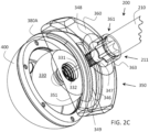
- a cutting assembly 350 having a mating portion 363 ( FIG. 2B ) is configured to be rotatably disposed within the through hole 145 of the orientation bearing 115.
- the mating portion 363 can comprise an outer circumferential surface. Referring briefly to FIGs.
- the inner surface 143 of the orientation is concentrically and closely disposed around the outer circumferential surface of the mating portion 363 when the cup remove instrument 1 is in the assembled configuration.
- the mating portion 363 can be said to be "configured to be rotatably disposed within the through hole 145 of the orientation bearing 115 .”
- the cutting assembly 350 comprises a cutting blade 380.
- a drive member 200 having a drive member body 210 extends between a drive member leading end 211 and a drive member trailing end 212.
- the leading end 211 of the drive member 200 engages the cutting assembly 350 to rotatably drive the cutting assembly 350 to cut around the acetabular cup implant 400 and thus detach the acetabular cup implant 400 from a patient's natural acetabulum.
- the positioning member 100 , drive member 200 orientation bearing 115 , and cutting assembly 350 can be made from medical grade stainless steel, titanium, or any other biocompatible material having similar strength and durability properties.
- the positioning member 100 is sized and configured to operate in or through a main incision
- the drive member 200 is sized and configured to operate in or through a portal incision.
- the exemplary cup remover assembly 1 includes a single fixed cutting blade 380 that can be rotated around the outer edge of an acetabular cup implant 400 (see FIG. 2A ).
- the positioning member 100 includes a longitudinal body 110 , such as a main shaft or an extension portion extending between a leading or lower end 111 and a trailing or upper end 112.
- An orientation bearing 115 is affixed to or can be integral with the leading end 111.
- the orientation bearing 115 is a ring member configured to rotatably receive and support a cutting assembly 350.
- a hand grip 120 is provided on or adjacent to the trailing end 112 of the longitudinal body 110.
- the hand grip 120 can be in the form of a T-handle, as shown in FIG. 1 .
- the hand grip 120 is configured for use in inserting the positioning member 100 and the cutting assembly 350 into a main incision that is aligned with the patient's hip joint.
- a partially engaged configuration, in which the positioning member 100 engages the cutting assembly 350 can be used to position the cutting assembly 350 over the patient's acetabulum and to seat a femoral head bearing 330 into the acetabular cup implant 400 that is to be removed.
- a cutting assembly 350 is rotatably attached adjacent to the leading end 111 of the positioning member 100 via the orientation bearing 115.
- the cutting assembly 350 comprises a blade support portion 360 rotatably connected to the orientation bearing 115 in an assembled or partially assembled configuration, a cutting blade 380 extending distally from the blade support portion 360 , and a femoral head bearing 330.
- the femoral head bearing 330 is positioned below the blade support portion 360.
- the femoral head bearing 330 is typically generally hemispherical and is typically sized for use in orienting the cup remover assembly 1 in the primary acetabular cup 400 (see FIG. 2A ).
- the femoral head bearing 330 may be rotatably connected below the blade support portion 360 such that the blade support portion 360 rotates around and independently of the femoral head bearing 330.
- the cutting blade 380 typically extends distally from the blade support portion 360 and has a curved or arcuate cross section generally matching an outer diameter of the acetabular cup implant 400 to be removed.
- the cutting blade 380 is positioned a selected distance from an outer diameter of the femoral head bearing 330 such that the cutting blade 380 cuts bone or bone cement adjacent an outer diameter of the acetabular cup implant 400 to be removed.
- a driver seat 361 ( FIG. 2C ) extension of the blade support portion 360 can be rotatably positioned in the orientation bearing 115 for use in rotating the blade support portion 360 and the cutting blade 380 , as described herein.
- a separate drive member 200 is provided for use in rotating the cutting assembly 350.
- the drive member 200 (see also FIG. 2B ) has a drive member body 210 extending between a drive member leading or lower end 211 and a drive member trailing or upper end 212.
- the drive member body 210 has been inserted through a portal guide assembly 250.
- the portal guide assembly 250 can comprise a portal guide 235 that can be inserted through a portal incision in the patient's leg if desired.
- the portal guide assembly 250 can be inserted through a cannula 500 ( FIG. 4A ).
- the portal guide assembly 250 may optionally include a drive handle 230 extending from the portal guide 235 adjacent to the drive member trailing end 212 in the assembled configuration.
- the drive handle 230 is desirably positioned and configured for use in rotating the drive member 200 to rotate the blade support portion 360 and the attached cutting blade 380 via the drive seat 361 when engaged.
- the drive handle 230 engages the drive member trailing end 212 in any manner appreciable by those having ordinary skill in the art, but desirably by a mechanical projection-receiver engagement mechanism as discussed below with reference to the leading end 211 of the drive member 200. In this manner, the drive handle 230 can be said to be “configured to” engage the drive member trailing end 212 to thereby rotate the drive member body 210 and the drive member leading end 211.
- the leading end 211 of the drive member 200 is configured to engage the drive seat 361 of the blade support member 360 , such as via a male hex on the leading end 211 and a female hex on the drive seat 361 , or vice versa. All projections and closely fitting receiver engagement mechanisms known to those having ordinary skill in the art are considered to be within the scope of this disclosure.
- the drive member leading end 211 can be said to be “configured to engage the cutting assembly 350 to rotatably drive the cutting assembly 350 .”
- a handle 220 is provided on or at the trailing end 212 of the drive member 200 for use in holding, inserting, removing, and manipulating the drive member 200 in the portal guide assembly 250 and into engagement with the drive seat 361 disposed within the orientation bearing 115 of the positioning member 100.
- a surgeon can selectively position the positioning member 100 in a main incision and the drive member 200 in a portal incision and selectively rotate the drive member 200 to rotate the cutting blade 380 around the acetabular cup implant 400 that is to be removed.
- the fixed cutting blade 380 is configured to be removable such that different sized cutting blades 380 can be selected for use in removing different sizes of cups.
- multiple sizes of blade support portions 360 , cutting blades 380 , and femoral head bearings 330 may be provided, such as in the form of an instrument kit arranged in a surgical tray.
- the blade support portion 360 has a length dimension that can be sized along with the cutting blade 380 to place the cutting blade 380 just outside of the outer diameter of the acetabular cup implant 400 to be removed.
- the size of the acetabular cup implant 400 is desirably known prior to surgery (e.g. , through patient records or pre-operative radiographs) such that the blade support portion 360 and the cutting blade 380 can be sized to accommodate the removal of the acetabular cup implant 400.
- more than one blade support portion 360 or cutting blade 380 having different size dimensions can be provided at the time of surgery to provide the surgeon with options when the surgeon encounters the actual acetabular cup implant 400 during the procedure.
- fixed cutting blades 380 having different blade lengths can be provided.
- a surgeon may use a shorter cutting blade 380 to initiate the removal of the acetabular cup implant 400.
- a shorter cutting blade 380 may create a useful opening between the natural acetabulum and the acetabular cup implant 400 around the outer circumference of the acetabular cup implant 400.
- a longer cutting blade 380 placed within the initial opening can be used to extend the opening between the acetabular cup implant 400 and the natural acetabulum to thereby separate the acetabular cup implant 400 from the natural acetabulum.
- Differently sized femoral head bearings 330 may be used to seat various sized acetabular cup implants 400.
- the various sizes are integral with a respective positioning member 100.
- the components may be removable from and detachable from a positioning member 100 so as to reduce instrument inventory.
- the cup remover assembly 1 is similar to the exemplary embodiment described with reference to FIG. 1 .
- the cutting blade 380 is selectively extendable from the blade support portion 360 (see FIG. 2C ). In the embodiment of FIGs. 2A - C , this is accomplished by providing a hollow portal guide 235 that houses the drive member body 210.
- An adjustment handle 220A is provided on the trailing end 212 , rather than the fixed handle 220 of the embodiment of FIG. 1 .
- the selectively extendable cutting blade 380A is operably connected to the drive member 200 ( FIG. 2B ) such that rotation of the adjustment handle 220A, e.g., as in a clockwise direction, selectively extends the cutting blade 380A.
- the surgeon can disengage the drive member 200 from the cutting assembly 350 to define a partially engaged position (i.e. , the orientation bearing 115 of the positioning member 100 is still disposed around the mating portion 363 of the cutting assembly 350 ).
- the surgeon may then use the handle 120 of the positioning member 100 to selectively move the cutting assembly 350 , and by extension, the selectively extendable cutting blade 380A around the outer surface of the acetabular cup implant 400 to thereby unseat the acetabular cup implant 400 from the patient's natural acetabulum.
- the length of the selectively extendable cutting blade 380A can be adjusted as needed relative to the bottom 351 of the cutting assembly support 360 during the procedure.
- FIG. 2C provides a close up view of an exemplary operable connection of the cutting blade 380 to the drive member 200.
- the leading end 211 of the drive member 200 comprises a male keyed shape, such as a hex shape.
- the male keyed shape is disposed in and engages the sides of a complementary keyed shape, such as a female hex shape on the drive seat 361.
- the drive seat member 361 can be said to have a proximal end that has a keyed interface that is "configured to mate" with a complementary keyed inface of the drive member leading end 211.
- the drive seat 361 is disposed within the mating portion 363 of the cutting assembly 350.
- the mating portion 363 is disposed within the hole 145 of the preferably annular inner surface 143 of the orientation bearing 115.
- the mating portion 363 can be said to be "configured to be rotatably disposed" within the hole 145 of the orientation bearing 115.
- an annular inner surface 143 comprises a preferred embodiment, any mechanical engagement that permits the mating portion 363 to be positioned relative to the movement of an engaged positioning member 100 is considered to be within the scope of this disclosure.
- the drive seat 361 is engaged to and shares a rotational axis with a spline shaft 347 comprising distal spline teeth 348.
- the distal spline teeth 348 in turn selectively engage geared teeth 349 of the extendable cutting blade 380.
- the geared teeth 349 can be oppositely disposed from a non-geared blade support side 346. In this manner, rotation of the adjustment handle 220A , e.g., as in a clockwise direction, selectively extends the cutting blade 380A relative to the bottom 351 of the blade support potion 360.
- the foregoing description is one example of how a blade support portion 360 can have a drive seat that is "configured to communicate with" the cutting blade 380.
- a sleeve may be closely disposed between the spline shaft 347 and an inner wall of the drive seat 361.
- Such a sleeve can provide a frictional force that prevents rotation of the spline shaft 347 when said frictional force is not overcome by the rotational movement of the engaged drive member 200.
- the sleeve can lock the spline shaft 347 , and by extension, the selectively extendable cutting blade 380A at the desired location, which can correspond to the desired length of the selectively extendable cutting blade 380A relative to the bottom 351 of the cutting assembly support 360.
- the spline shaft 347 may be generally cylindrically and annularly disposed around a fixed femoral head bearing support 331 in exemplary embodiments.
- the fixed femoral head bearing support 331 extends beyond the spline shaft 347 and desirably supports a femoral head engagement mechanism 332.
- the femoral head engagement mechanism is configured to detachably engage a femoral hear bearing 330.
- Exemplary femoral head engagement mechanisms 332 can comprise a screw thread, a ball bearing in a complementary socket, a clamp, a protrusion, a recess, and other known means to selectively engage and disengage one component from another mechanically.
- FIG. 3 shows an alternative embodiment of a selectively extendable cutting blade 380A in which the extension of the blade 380 is timed to the rotation of the drive handle 230.
- the blade 380 extends a small amount relative to the bottom 351 of the cutting assembly support 360 with each rotation of the drive handle 230. In this manner, the cutting blade 380 cuts deeper with each rotation.
- this is accomplished by providing the drive member 200 (see FIG. 2B ) through the portal guide 235 of the portal guide assembly 250.
- the portal guide assembly 250 may optionally further comprise a fixed handle 240 on the upper portion of the portal guide 235 for use in holding and manipulating the dive member 200.
- the portal guide assembly 250 can be inserted through a portal incision in the patient's leg if desired.
- the portal guide assembly 250 can be inserted through a cannula 500 ( FIG. 4A ).
- the cutting blade 380 is operably connected to the internal drive member 200 such that rotation of the drive handle 230, e.g., as in a clockwise direction, selectively extends the cutting blade 380.
- the cutting blade 380 is operatively connected to the drive member 200 and can be selectively lockable in the same way as described with reference to FIG. 2C above.
- the detachable cup remover assembly 1 of the present disclosure includes a powered hemispherical cutting blade 380B.
- the hemispherical cutting blade 380B has a hollow hemispherical interior and an annular rim on a lower end thereof.
- the hemispherical cutting blade 380B is provided with a cutting edge (see 383 ) along the annular bottom rim, such as a serrated edge or serrations in the manner of a saw blade.
- the hemispherical cutting blade 380B desirably comprises one or more evacuation holes 385 extending through a blade body of the hemispherical cutting blade 380B.
- the evacuation holes 385 permit removed bone cement, bone, marrow, or other tissue to exit the drilling area without unduly interfering with the cutting process.
- various sizes of hemispherical blades 380B are provided such that the blade 380B can be selectively matched to the size of a primary or revision acetabular cup implant 400 to be removed.
- the annular rim is selectively sized to extend a cutting end of the hemispherical cutting blade 380B around the fixed primary or revision acetabular cup implant 400.
- the hemispherical cutting blade 380B can be power driven by the drive member 200 , which in this embodiment takes the form of a portal drive shaft 200A.
- a trailing end 212 of the portal drive shaft 200A is provided with a standard configuration for engagement by an electric drill or other power drive mechanism, such as an engagement flat or flats.
- the T-handle 120 of the positioning member 100 can be used to move the hemispherical blade 380B around the outer diameter of the primary or revision acetabular cup implant 400 during cutting.
- FIG. 4B shows the hemispherical cutting blade 380B oriented directly over the acetabular cup implant 400 in a starting position.
- FIG. 4C shows the hemispherical cutting blade 380B rotated around a side of the acetabular cup implant 400 to assist in cutting deeper areas of the adjacent bone or bone cement.
- the powered hemispherical cutting blade 380B while powerful, presents several design limitations. Depending on the size of the inner diameter of the acetabular cup implant 400 , a liner insert 401 may be needed in order to maintain the hemispherical cutting blade 380B in a concentric orientation with the outer diameter of the primary or revision acetabular cup implant 400. Liner inserts 401 can be provided to accommodate various sizes of acetabular cup implants 400 and hemispherical cutting blades 380B. Additionally, it is contemplated that the use of a portal drive shaft 200A having a ball end, universal j oint (see 209, FIG. 5 ) or a gimbled connection (not shown) will improve maneuverability of any of the blades 380 considered to be within the scope of this disclosure around the acetabular cup insert 400 during cutting.
- the serrated edge comprises serrated teeth 383 extending from a circumference C of the hemispherical cutting blade 380B.
- the serrated teeth 383 have an outer surface angle ⁇ defined by the intersection between a normal line N to the circumference C of the hemispherical cutting blade 380B and the plane defined by an outer surface S of a serrated tooth 383A of the serrated teeth 383.
- the outer surface angle ⁇ is desirably less than 10 degrees.
- the outer surface angle ⁇ can be a compound angle comprising the sum of multiple angles, including for example, combinations of outer surface angles and normal angles.
- the outer surface S of the serrated tooth 383A can comprise multiple outer surface angles ⁇ wherein the second and any subsequent angles disposed below an initial angle, the initial angle being disposed closest to the circumference C , are greater than the preceding outer surface angle ⁇ relative to the normal line N.
- the serrated teeth 383 may have a portion that is coextensive with the normal line N and be angled relative to a line that is coplanar with the normal plane to define a normal angle.
- outer surface S of the serrated tooth 383A can comprise multiple normal angles wherein the second and any subsequent angles are greater than the preceding normal angle relative to the line that is coplanar with the normal plane.
- a hemispherical cutting blade 380B having serrated teeth 383 with an outer surface angle ⁇ of desirably less than 10 degrees applies a pulling force on the acetabular cup implant 400 during active use. That is, the hemispherical cutting blade 380B with the serrated teeth 383 described herein may facilitate the removal of the acetabular cup implant 400 by drawing the acetabular cup implant 400 toward the bottom 351 of the cutting assembly support 360 during normal use. As a result, it is contemplated that surgeons may be able to spend less time removing prior-implanted acetabular cup implants 400 , to thereby reduce procedure time and its ancillary risks.
- the components of the cup remover instrument assembly 1 will typically be arranged in a convenient format, such as in a surgical tray or case, in the manner of a kit.
- the kit components do not have to be packaged or delivered together, provided that they are assembled or collected together in the operating room for use at the time of surgery.
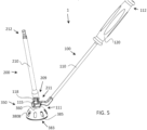
- FIG. 5 is a side perspective view of another exemplary embodiment of the present disclosure in which the orientation bearing 115 is directly integrally engaged to the leading end 111 of the positioning member 100 and wherein the annular inner surface 143 of the orientation bearing 115 further comprises ball bearings 118 disposed within the orientation bearing 115 and extending into the hole 145 of the orientation bearing 115.
- the ball bearings 118 can be closely disposed adjacent to a track in the cutting assembly support 360 to facilitate the rotational movement of the cutting assembly support 360 relative to the orientation bearing 115.
- the drive member 200 comprises a universal joint 209 at the drive member leading end 211 .
- the drive member 200 which is a portal drive shaft as in the depicted embodiment, may be inserted through a portal incision in the patient's leg that aligns with the exposed surgical area.
- the exposed surgical area can be defined by a main surgical incision positioned over the patient's joint capsule relative to the surgeon's point of view.
- the surgeon may place the cutting assembly 350 comprising a cutting assembly support 360 and a hemispherical cutting blade 380 into the main incision.
- the cutting assembly 350 may be rotatably engaged to the orientation bearing 115 , which is in turn directly or indirectly engaged to the positioning member 100 while inserted into the main incision.
- the drive member 200 may be inserted into the portal incision.
- a cannula 500 or other tube may be inserted through the portal incision prior to the insertion of the drive member 200.
- a cannula 500 or other liner can be desirable to preserve patient tissue surrounding the portal incision in view of the rotational movement of the drive member 200.
- the presence of the universal joint 209 permits the surgeon to use the positioning member 100 to adjust the position of the hemispherical cutting blade 380B in an arcuate manner relative to the acetabular cup implant 400 (see FIGs. 4B and 4C ) while maintaining the rotational movement of the hemispherical cutting blade 280B around a center rotational axis R via the drive member 200.
- Such an embodiment may permit surgeons to use a portal incision and main incision minimally invasive technique to remove the prior-installed acetabular cup implant 400 in a revision hip arthroplasty procedure. It is contemplated that the speed at which this may be accomplished could reduce the overall time that the patient is under anesthesia, reduce procedure time, and therefore the risk of infection, while maintaining the enhanced recovery time associated with minimally invasive procedures.
- FIG. 6 is a side perspective view of an exemplary cup remover instrument assembly 1 that is similar to the embodiment described with reference to FIG. 5 , except that the positioning member 100 further comprises an articulating clamp 119 at the leading end 111.
- the articulating clamp 119 comprises a first arm 117a and a second arm 117b oppositely and distally disposed to the first arm 117a.
- Pins 113a, 113b extend through aligned pin holes in the orientation bearing 115 and in the first arm 117a and the second arm 117b to indirectly engage the orientation bearing 115 to the leading end 111 of the positioning member 100. In this manner, the positioning member 100 can be said to "indirectly engage" the orientation bearing 115.
- the T handle 120 of the positioning member 100 engages a trailing end of a follower 106.
- the surgeon can apply a counter force when pressing the T handle 120 and the follower 106 toward the leading end 111 of the positioning member 100.
- the follower 106 extends generally within the positioning member 100 along the length of the positioning member 100 until the follower 106 reaches the articulating clamp 119.
- a surgeon can push the follower 106 toward the leading end 111 to extend the first arm 117a and the second arm 117b away from one another to release the orientation bearing 115.
- FIG. 7 is similar to the exemplary embodiment of FIG. 6 except that the body 110 of the positioning member 100 comprises a grip 121 that extends generally lengthwise along the length of the body 110 of the positioning member 100.
- the follower 106 may engage a T handle 120 as shown in FIG. 6 , a different type of handle, or no handle at all.
- the instruments that comprise the exemplary cup remover instrument assembly 1 can be provided in the form of a kit.
- the components of the kit are preferably arranged in a convenient format, such as in a surgical tray or case. However, the kit components do not have to be packaged or delivered together, provided that they are assembled or collected together in the operating room for use at the time of surgery.
- An exemplary kit can include any suitable embodiment of a cup remove instrument assembly 1 , variations of the cup remove instrument assembly 1 described herein, and any other cup remove instrument assembly 1 according to an embodiment.
- an exemplary kit may further include one or more cutting assemblies 350 , one or cutting blades 380 , one or more types of cutting blades 380, (e.g., selectively extendable cutting blades 380A , or hemispherical cutting blades 380B ), one or more drive members 200 , one or more cutting assembly supports 360 , one or more orientation bearings 115 , and one or more positioning members 100 , it will be appreciated that certain kits may lack some or all of these elements. Any suitable embodiment of a cutting assembly 350 , variations of the cutting assemblies 350 described herein, and any other cutting assemblies 350 according to an embodiment are considered to be within the scope of this disclosure.
- Any suitable embodiment of a cutting blade 380 , variations of the cutting blades 380 described herein, and any other cutting blade 380 according to an embodiment are considered to be within the scope of this disclosure.
- Any suitable embodiment of a drive member 200 , variations of the drive members 200 described herein, and any other drive member 200 according to an embodiment are considered to be within the scope of this disclosure.
- Any suitable embodiment of a cutting assembly support 360 , variations of the cutting assembly supports 360 described herein, and any other cutting assembly support 360 according to an embodiment are considered to be within the scope of this disclosure.
- Any suitable embodiment of an orientation bearing 115 , variations of the orientation bearings 115 described herein, and any other orientation bearing 115 according to an embodiment are considered to be within the scope of this disclosure.
- Any suitable embodiment of a positioning member 100 , variations of the positioning members 100 described herein, and any other positioning member 100 according to an embodiment are considered to be within the scope of this disclosure.
- Selection of a suitable number or type of cup remover instrument assembly 1 , cutting assembly 350 , cutting blade 380 , drive member 200 , cutting assembly support 360 , orientation bearing 115 , and positioning member 100 to include in a kit according to a particular embodiment can be based on various considerations, such as the procedure intended to be performed using the components included in the kit.
- the cup remover 1 is configured for use in a two-incision hip procedure, such as those discussed in the background section.
- two-incision hip procedures a main incision provides access to the hip joint, while a nearby portal incision communicates with the hip joint. Relatively large instruments are inserted into the hip joint through the main incision, while the portal incision is used to drive or otherwise operates the instruments located in the hip joint.
- Two-incision hip procedures have traditionally been used for primary hip procedures.
- the cup remover 1 of the invention is designed for use in two-incision revision procedures.
- the positioning member 100 is sized and configured to operate in or through a main incision
- the drive member 200 is sized and configured to operate in or through a portal incision.
- the positioning member can be manipulated in the main incision via the hand grip 120 and the upper portion of the extension portion 120.
- the configuration of the drive member 200 allows it to be inserted through a portal incision and operated via the handle 220 and drive handle 230 portions. If a cannula 500 is used in the portal incision, a portal drive shaft 200 can be inserted into the cannula 500 and used to drive the cutting blade 380.
- An exemplary medical device assembly comprises: an orientation bearing having an inner surface defining a hole, a positioning member engaged to the orientation bearing, the positioning member having a longitudinal body extending between a leading end and a trailing end, a cutting assembly having a mating portion configured to be rotatably disposed within the hole of the orientation bearing, wherein the cutting assembly comprises a cutting blade, and a drive member having a drive member body extending between a drive member leading end and a drive member trailing end, wherein the drive member leading end is configured to engage the cutting assembly to rotatably drive the cutting assembly.
- the medical device assembly can further comprise a femoral head bearing disposed below a blade support portion.
- the cutting assembly can further comprise: a blade support portion rotatably connected to the cutting assembly support.
- the blade support portion is a drive seat configured to communicate with the cutting blade, and the cutting blade extends distally from the blade support portion, and the leading end of the drive member is configured to engage the drive seat.
- the orientation bearing is integrally engaged to the leading end of the positioning member. In another exemplary embodiment, the orientation bearing is indirectly engaged to the leading end of the positioning member.
- the cutting blade is a hemispherical cutting blade.
- the hemispherical cutting blade may further comprise serrated teeth extending from a distal circumference of the hemispherical cutting blade.
- the serrated teeth may further have an outer surface angle defined by an angle between a normal line to the distal circumference of the hemispherical cutting blade and an outer surface of a serrated tooth of the serrated teeth. In such an embodiment, the outer surface angle may be less than 10 degrees.
- the hemispherical cutting blade further defines an evacuation hole extending through a blade body of the hemispherical cutting blade.
- the hemispherical cutting blade may further define a plurality of evacuation holes extending through a blade body of the hemispherical cutting blade.
- the cutting assembly further comprises a cutting assembly support, and wherein the cutting assembly support has the mating portion configured to be rotatably disposed within the hole of the orientation bearing.
- the medical device assembly may further comprise a drive seat member disposed between the cutting assembly support and the drive member in an assembled configuration.
- the cutting assembly support may have a drive seat member configured to communicate with the cutting blade, the cutting blade can extend distally from the cutting assembly support, and the leading end of the drive member can be configured to engage the drive seat.
- the drive seat member may comprise a proximal end having a keyed interface configured to mate with a complementary keyed inface of the drive member leading end.
- the cutting blade is a curved cutting blade, wherein a spline shaft extends distally from the keyed interface, and wherein geared teeth on a distal end of the spline shaft engage complementary geared teeth of the curved cutting blade disposed in the cutting assembly support such that a rotational movement of the spline shaft translates into an arcuate movement of the curved cutting blade.
- the positioning member may further comprise an articulating clamp at the leading end, the articulating clamp may comprise a first arm and a second arm, and pins may extend through aligned pin holes in the orientation bearing and the first arm and the second arm to indirectly engage the orientation bearing to the positioning member.
- the medical device assembly may further comprise a handle disposed at the trailing end of the positioning member.
- the medical device assembly may further comprise a drive handle configured to engage the drive member trailing end to thereby rotate the drive member body and the drive member leading end.
- the cutting assembly is rotatably engaged to the cutting assembly support.
- the medical device assembly can further comprise a cannula, wherein the drive member is disposed within the cannula.
- An exemplary medical device assembly can comprise: a cutting assembly support having a drive seat configured to communicate with a curved cutting blade, the curved cutting blade extending distally from the cutting assembly support, and a drive member having a drive member body extending between a drive member leading end and a drive member trailing end, wherein the drive member is configured to engage the drive seat to arcuately extend the curved cutting blade.
- An exemplary medical device assembly can comprise: an orientation bearing having an inner surface defining a hole; a positioning member engaged to the orientation bearing, the positioning member having a longitudinal body extending between a leading end and a trailing end, a cutting assembly support having a mating portion configured to be rotatably disposed within the hole of the orientation bearing, a cutting assembly engaged to the cutting assembly support, wherein the cutting assembly comprises a cutting blade, and, a drive member having a drive member body extending between a drive member leading end and a drive member trailing end, wherein the drive member trailing end is configured to engage the cutting assembly support to rotatably drive the cutting assembly.
Abstract
Description
- The present disclosure relates to instruments and methods for orthopedic surgery, and more particularly to instruments and methods for the removal of acetabular hip cup implants in total hip arthroplasties.
- In a total hip arthroplasty ("THA"), deteriorated cartilage in the acetabulum is replaced with an artificial hip cup. The artificial hip cup interacts with a ball head of an artificial hip stem to provide an artificial hip joint. In some hip implant designs, the cup consists of a unibody cup that is secured in the acetabulum, such as by bone ingrowth, bone cement, or screws. In other hip implant designs, the cup comprises an outer shell that is secured in the acetabulum in the foregoing manner and a separate cup liner that is inserted in the shell between the outer shell and the ball head of the artificial hip stem.
- The initial or "primary" hip implant typically lasts in a patient for about ten to twenty years. When the primary hip implant wears out, it is often useful to "revise" the primary hip implant by replacing it with new components. Revision typically includes removal and replacement of the primary acetabular cup. Additionally, when a revision cup wears out, it is typically desirable to remove and replace it.
- Examples of prior cup removers that use a cutting blade to loosen the hip cup from the acetabulum include the cup removers disclosed in
PCT App. No. WO2015/155657 (to Giardiello, et. al ) andU.S. Patent 6,565,575 (to Lewis ). However, these designs are intended for use in conventional THAs. A THA is typically performed through a relatively large incision (e.g., between about 20 centimeters ("cm") to about 30.5 cm (8 to 12 inches)) to provide sufficient access to the j oint. The large incision also permits the introduction and manipulation of instruments within the joint. Large incisions may increase operating time and cause patients to lose substantial amounts of blood, inflict significant trauma to surrounding tissues (e.g., the nerves and muscles), increase the risk of infection, and require longer recovery periods. - Furthermore, the Giardiello and Lewis devices have modular cutting blades of different lengths and curvatures. A short thick blade may be used to start an opening between the hip cup and the acetabulum, while a longer increasingly curved blade may be used to expand the opening and remove the hip cup. These devices require that the cup remover be partially disassembled prior to replacing the modular cutting blades. This practice increases procedure duration and therefore necessarily increases the surgery's ancillary risks, including the infection risk and the possibility of complications arising from increased time under anesthesia.
- In recent years, efforts have been made to develop "minimally invasive" procedures that reduce the incision length required for THA, with the aim of reducing blood loss, trauma, risk of infection, and recovery time. See
U.S. Patent No. 6,905,502 (to Brad Penenberg, M.D. ) and its family members (e.g.,U.S. Patent Nos. 6,997,928 ;7,833,229 ; and6,997,928 ). These patents describe the earliest efforts to use a small portal incision in conjunction with a larger main incision in order to prepare the acetabulum for receipt of a hip implant using a posterior approach. Refinements of these instruments and methods are described inU.S. Patent 7,651,501 (to Brad Penenberg, M.D. ) and its progeny (e.g.,U.S. Patent Nos. 8,439,928 ;9,180,023 9,539,113 U.S. Patent Application No. 2008/0009874 A1 discloses an apparatus for reaming an acetabulum through a single large incision. - However, when it comes to revision procedures, cup removal instruments have remained wedded to the single incision concept. There is a need for cup removers that can be used in minimally invasive two-incision techniques. Thus, there is a need for the techniques described herein below, which enable a reduced incision, good visualization, and other benefits that have not been obtained in conventional revision procedures.
- The problems associated with lengthy procedure duration and a large incision in a revision hip arthroplasty, including but not necessarily limited to an increased risk of patient infection, significant blood loss, trauma to the surrounding tissue, increased healing times, and complications arising from prolonged time under anesthesia can be mitigated by the assemblies or methods, or a combination of assemblies and methods in accordance with this disclosure. One such exemplary medical device assembly can comprise: an orientation bearing having an inner surface defining a hole, a positioning member engaged to the orientation bearing, the positioning member having a longitudinal body extending between a leading end and a trailing end, a cutting assembly having a mating portion configured to be rotatably disposed within the hole of the orientation bearing, wherein the cutting assembly comprises a cutting blade, and, a drive member having a drive member body extending between a drive member leading end and a drive member trailing end, wherein the drive member trailing end is configured to engage the cutting assembly to rotatably drive the cutting assembly. The present invention is defined in the appended claims.
- It is contemplated that exemplary instrument assemblies in accordance with the present disclosure may provide an acetabular cup remover instrument assembly for use in hip arthroplasty revision procedures.
- It is contemplated that certain exemplary instrument assemblies in accordance with the present disclosure may provide a cup remover assembly configured for use in minimally invasive hip procedures carried out through a primary and a portal incision.
- It is further contemplated that certain exemplary instrument assemblies in accordance with the present disclosure may provide an acetabular cup remover assembly configured for use with a cannula in hip arthroplasty procedures.
- Methods of using the instrument assembly and presenting the parts of the exemplary assemblies in kits are also described.
- The foregoing and other features, aspects and advantages of the invention will become more apparent from the following detailed description of the invention when considered in conjunction with the accompanying drawings.
-
-
FIG. 1 is a front-side perspective view of one exemplary embodiment of an acetabular cup remover assembly in the assembled configuration featuring a single fixed cutting blade. -
FIG. 2A is a front-side perspective view of one exemplary embodiment of an acetabular cup remover assembly in the assembled configuration featuring an extendable cutting blade. -
FIG. 2B is an exploded perspective view of the exemplary acetabular cup remover assembly ofFIG. 2A in the disassembled configuration. -
FIG. 2C is a detailed perspective view of the exemplary cutting assembly and exemplary cutting assembly support ofFIGS. 2A and2B and the acetabular shell implant. -
FIG. 3 is a front-side perspective view of an exemplary embodiment of an acetabular cup remover assembly in the assembled configuration featuring an extendable cutting blade, with the extension of the cutting blade timed to the rotation of a handle. -
FIG. 4A is a side perspective view of an exemplary embodiment of a cup remover assembly in a partially assembled configuration featuring a hemispherical cutting blade. -
FIG. 4B is a side perspective view of the hemispherical cutting blade ofFIG. 4A showing the hemispherical cutting blade aligned over the top of an acetabular shell implant (i.e., a hip cup). -
FIG. 4C is a perspective side view of the hemispherical cutting blade ofFIG. 4A showing the hemispherical cutting blade aligned to cut around the side of the acetabular shell implant. -
FIG. 4D is a close up perspective view of the hemispherical cutting blade ofFIG. 4A , which further details serrated teeth extending from a circumference of the hemispherical cutting blade. -
FIG. 4E is a close up side cross sectional view of the hemispherical cutting blade ofFIG. 4A further detailing a cross section of a serrated tooth to further illustrate the outer surface angle. -
FIG. 5 is a perspective side view of another exemplary embodiment of a cup remover assembly in the assembled configuration featuring a hemispherical cutting blade, an orientation bearing integrally engaged to the leading end of a positioning member, and a cutting assembly support rotatably engaged to the drive member via a universal joint. -
FIG. 6 is a side perspective view of an exemplary embodiment of a cup remover assembly in the assembled configuration in which the positioning member further comprises an articulating clamp comprising a first arm and a second arm configured to indirectly engage the orientation bearing. -
FIG. 7 is a side perspective view of an exemplary embodiment of a cup remover assembly in the assembled configuration similar to the embodiment ofFIG. 6 but having a more ergonomic handle. - In the following detailed description of the preferred embodiments, reference is made to the accompanying drawings which form a part hereof, and in which are shown by way of illustration, specific embodiments in which the invention may be practiced.
- The following detailed description of the preferred embodiments is presented only for illustrative and descriptive purposes and is not intended to be exhaustive or to limit the scope of the invention. The embodiments were selected and described to best explain the principles of the invention and its practical application. One of ordinary skill in the art will recognize that many variations can be made to the invention disclosed in this specification without departing from the scope of the invention.
- Similar reference characters indicate corresponding parts throughout the several views unless otherwise stated. Although the drawings represent embodiments of various features and components according to the present disclosure, the drawings are not necessarily to scale and certain features may be exaggerated to better illustrate embodiments of the present disclosure, and such exemplifications are not to be construed as limiting the scope of the present disclosure.
- Except as otherwise expressly stated herein, the following rules of interpretation apply to this specification: (a) all words used herein shall be construed to be of such gender or number (singular or plural) as such circumstances require; (b) the singular terms "a," "an," and "the," as used in the specification and the appended claims include plural references unless the context clearly dictates otherwise; (c) the antecedent term "about" applied to a recited range or value denotes an approximation with the deviation in the range or values known or expected in the art from the measurements; (d) the words, "herein," "hereby," "hereto," "hereinbefore," and "hereinafter," and words of similar import, refer to this specification in its entirety and not to any particular paragraph, claim, or other subdivision, unless otherwise specified; (e) descriptive headings are for convenience only and shall not control or affect the meaning of construction of part of the specification; and (f) "or" and "any" are not exclusive and "include" and "including" are not limiting. Further, the terms, "comprising," "having," "including," and "containing" are to be construed as open-ended terms (i.e., meaning "including but not limited to").
- Recitation of ranges of values herein are merely intended to serve as a shorthand method of referring individually to each separate value falling within the range of any sub-ranges there between, unless otherwise clearly indicated herein. Each separate value within a recited range is incorporated into the specification or claims as if each separate value were individually recited herein. Where a specific range of values is provided, it is understood that each intervening value, to the tenth or less of the unit of the lower limit between the upper and lower limit of that range and any other stated or intervening value in that stated range of sub range thereof, is included herein unless the context clearly dictates otherwise. All subranges are also included. The upper and lower limits of these smaller ranges are also included therein, subject to any specifically and expressly excluded limit in the stated range.
- It should be noted that some of the terms used herein are relative terms. For example, the terms, "upper" and "lower," "above" and "below" are relative to each other in location, i.e., an upper component is located at a higher elevation than a lower component in the indicated or depicted orientation, but these terms can change if the orientation is flipped.
- The terms, "horizontal" and "vertical" are used to indicate direction relative to an absolute reference, i.e., ground level. However, these terms should not be construed to require structure to be absolutely parallel or absolutely perpendicular to each other. For example, a first vertical structure and a second vertical structure are not necessarily parallel to each other.
- As indicated in
FIGS. 1-7 , exemplary embodiments of the detachable acetabular cupremover instrument assembly 1 are configured for use in removing a primary acetabular cup or combination of cup and shell 400 (FIG. 2A ) (collectively, "primary cup") in a revision hip procedure. Although theinstrument 1 is described herein for removal of primary cups, it can be used to remove revision cups when revision cups are present. - The exemplary cup
remover instrument assemblies 1 described herein have an assembled configuration (see e.g.,FIG. 2A ), a disassembled configuration (seeFIG. 2B ), and partially assembled configurations. - The exemplary cup
remover instrument assemblies 1 include, generally, apositioning member 100 comprising alongitudinal body 110, aleading end 111, and a trailingend 112. Thelongitudinal body 110 extends between theleading end 111 and the trailingend 112. The positioning member engages an orientation bearing 115 having an inner surface 143 (FIG. 2B ) defining a through hole 145 (FIG. 2B ). A cuttingassembly 350 having a mating portion 363 (FIG. 2B ) is configured to be rotatably disposed within the throughhole 145 of the orientation bearing 115. Referring briefly toFIG. 2C , themating portion 363 can comprise an outer circumferential surface. Referring briefly toFIGs. 2A and2B , theinner surface 143 of the orientation is concentrically and closely disposed around the outer circumferential surface of themating portion 363 when the cup removeinstrument 1 is in the assembled configuration. In this manner, themating portion 363 can be said to be "configured to be rotatably disposed within the throughhole 145 of the orientation bearing 115." - The cutting
assembly 350 comprises acutting blade 380. Adrive member 200 having a drive member body 210 (FIG. 2B ) extends between a drivemember leading end 211 and a drivemember trailing end 212. Theleading end 211 of thedrive member 200 engages the cuttingassembly 350 to rotatably drive the cuttingassembly 350 to cut around theacetabular cup implant 400 and thus detach theacetabular cup implant 400 from a patient's natural acetabulum. It is contemplated that thepositioning member 100,drive member 200 orientation bearing 115, and cuttingassembly 350 can be made from medical grade stainless steel, titanium, or any other biocompatible material having similar strength and durability properties. - Various configurations of cutting arrangements and drive mechanisms for operating the various cutting arrangements will be described herein. In certain exemplary embodiments, the positioning
member 100 is sized and configured to operate in or through a main incision, while thedrive member 200 is sized and configured to operate in or through a portal incision. - In the embodiment of
FIG. 1 , the exemplary cup removerassembly 1 includes a singlefixed cutting blade 380 that can be rotated around the outer edge of an acetabular cup implant 400 (seeFIG. 2A ). The positioningmember 100 includes alongitudinal body 110, such as a main shaft or an extension portion extending between a leading orlower end 111 and a trailing orupper end 112. An orientation bearing 115 is affixed to or can be integral with theleading end 111. In exemplary embodiments, the orientation bearing 115 is a ring member configured to rotatably receive and support a cuttingassembly 350. In embodiments, ahand grip 120 is provided on or adjacent to the trailingend 112 of thelongitudinal body 110. Thehand grip 120 can be in the form of a T-handle, as shown inFIG. 1 . Thehand grip 120 is configured for use in inserting thepositioning member 100 and the cuttingassembly 350 into a main incision that is aligned with the patient's hip joint. A partially engaged configuration, in which thepositioning member 100 engages the cuttingassembly 350 can be used to position the cuttingassembly 350 over the patient's acetabulum and to seat a femoral head bearing 330 into theacetabular cup implant 400 that is to be removed. - A cutting
assembly 350 is rotatably attached adjacent to theleading end 111 of thepositioning member 100 via the orientation bearing 115. In the depicted embodiment, the cuttingassembly 350 comprises ablade support portion 360 rotatably connected to the orientation bearing 115 in an assembled or partially assembled configuration, acutting blade 380 extending distally from theblade support portion 360, and a femoral head bearing 330. The femoral head bearing 330 is positioned below theblade support portion 360. The femoral head bearing 330 is typically generally hemispherical and is typically sized for use in orienting thecup remover assembly 1 in the primary acetabular cup 400 (seeFIG. 2A ). The femoral head bearing 330 may be rotatably connected below theblade support portion 360 such that theblade support portion 360 rotates around and independently of the femoral head bearing 330. As shown inFIG. 1 , thecutting blade 380 typically extends distally from theblade support portion 360 and has a curved or arcuate cross section generally matching an outer diameter of theacetabular cup implant 400 to be removed. Thecutting blade 380 is positioned a selected distance from an outer diameter of the femoral head bearing 330 such that thecutting blade 380 cuts bone or bone cement adjacent an outer diameter of theacetabular cup implant 400 to be removed. A driver seat 361 (FIG. 2C ) extension of theblade support portion 360 can be rotatably positioned in the orientation bearing 115 for use in rotating theblade support portion 360 and thecutting blade 380, as described herein. - A
separate drive member 200 is provided for use in rotating the cuttingassembly 350. The drive member 200 (see alsoFIG. 2B ) has adrive member body 210 extending between a drive member leading orlower end 211 and a drive member trailing orupper end 212. In the embodiment ofFIG. 1 , thedrive member body 210 has been inserted through aportal guide assembly 250. Theportal guide assembly 250 can comprise aportal guide 235 that can be inserted through a portal incision in the patient's leg if desired. In other exemplary embodiments, theportal guide assembly 250 can be inserted through a cannula 500 (FIG. 4A ). Theportal guide assembly 250 may optionally include adrive handle 230 extending from theportal guide 235 adjacent to the drivemember trailing end 212 in the assembled configuration. Thedrive handle 230 is desirably positioned and configured for use in rotating thedrive member 200 to rotate theblade support portion 360 and the attachedcutting blade 380 via thedrive seat 361 when engaged. Thedrive handle 230 engages the drivemember trailing end 212 in any manner appreciable by those having ordinary skill in the art, but desirably by a mechanical projection-receiver engagement mechanism as discussed below with reference to theleading end 211 of thedrive member 200. In this manner, the drive handle 230 can be said to be "configured to" engage the drivemember trailing end 212 to thereby rotate thedrive member body 210 and the drivemember leading end 211. - The
leading end 211 of thedrive member 200 is configured to engage thedrive seat 361 of theblade support member 360, such as via a male hex on theleading end 211 and a female hex on thedrive seat 361, or vice versa. All projections and closely fitting receiver engagement mechanisms known to those having ordinary skill in the art are considered to be within the scope of this disclosure. In this manner, the drivemember leading end 211 can be said to be "configured to engage the cuttingassembly 350 to rotatably drive the cuttingassembly 350." Ahandle 220 is provided on or at the trailingend 212 of thedrive member 200 for use in holding, inserting, removing, and manipulating thedrive member 200 in theportal guide assembly 250 and into engagement with thedrive seat 361 disposed within the orientation bearing 115 of thepositioning member 100. - Using the configuration described herein, a surgeon can selectively position the positioning
member 100 in a main incision and thedrive member 200 in a portal incision and selectively rotate thedrive member 200 to rotate thecutting blade 380 around theacetabular cup implant 400 that is to be removed. - In order to accommodate and remove diverse sizes of acetabular cup implants (i.e., hip cups), the fixed
cutting blade 380 is configured to be removable such that differentsized cutting blades 380 can be selected for use in removing different sizes of cups. In exemplary embodiments, multiple sizes ofblade support portions 360, cuttingblades 380, andfemoral head bearings 330 may be provided, such as in the form of an instrument kit arranged in a surgical tray. - For example, it is contemplated that the
blade support portion 360 has a length dimension that can be sized along with thecutting blade 380 to place thecutting blade 380 just outside of the outer diameter of theacetabular cup implant 400 to be removed. The size of theacetabular cup implant 400 is desirably known prior to surgery (e.g., through patient records or pre-operative radiographs) such that theblade support portion 360 and thecutting blade 380 can be sized to accommodate the removal of theacetabular cup implant 400. However, it is also contemplated that more than oneblade support portion 360 or cuttingblade 380 having different size dimensions can be provided at the time of surgery to provide the surgeon with options when the surgeon encounters the actualacetabular cup implant 400 during the procedure. - It is further contemplated that fixed
cutting blades 380 having different blade lengths can be provided. A surgeon may use ashorter cutting blade 380 to initiate the removal of theacetabular cup implant 400. For example, ashorter cutting blade 380 may create a useful opening between the natural acetabulum and theacetabular cup implant 400 around the outer circumference of theacetabular cup implant 400. Alonger cutting blade 380 placed within the initial opening can be used to extend the opening between theacetabular cup implant 400 and the natural acetabulum to thereby separate theacetabular cup implant 400 from the natural acetabulum. - Differently sized
femoral head bearings 330 may be used to seat various sizedacetabular cup implants 400. In exemplary embodiments, the various sizes are integral with arespective positioning member 100. In other embodiments, the components may be removable from and detachable from apositioning member 100 so as to reduce instrument inventory. - In the embodiment of
FIGs. 2A - C , thecup remover assembly 1 is similar to the exemplary embodiment described with reference toFIG. 1 . However, thecutting blade 380 is selectively extendable from the blade support portion 360 (seeFIG. 2C ). In the embodiment ofFIGs. 2A - C , this is accomplished by providing a hollowportal guide 235 that houses thedrive member body 210. An adjustment handle 220A is provided on the trailingend 212, rather than the fixedhandle 220 of the embodiment ofFIG. 1 . The selectivelyextendable cutting blade 380A is operably connected to the drive member 200 (FIG. 2B ) such that rotation of the adjustment handle 220A, e.g., as in a clockwise direction, selectively extends thecutting blade 380A. Once a desired cutting blade length has been set, the surgeon can disengage thedrive member 200 from the cuttingassembly 350 to define a partially engaged position (i.e., the orientation bearing 115 of thepositioning member 100 is still disposed around themating portion 363 of the cutting assembly 350). The surgeon may then use thehandle 120 of thepositioning member 100 to selectively move the cuttingassembly 350, and by extension, the selectivelyextendable cutting blade 380A around the outer surface of theacetabular cup implant 400 to thereby unseat theacetabular cup implant 400 from the patient's natural acetabulum. The length of the selectivelyextendable cutting blade 380A can be adjusted as needed relative to thebottom 351 of the cuttingassembly support 360 during the procedure. -
FIG. 2C provides a close up view of an exemplary operable connection of thecutting blade 380 to thedrive member 200. In the assembled configuration, theleading end 211 of thedrive member 200 comprises a male keyed shape, such as a hex shape. The male keyed shape is disposed in and engages the sides of a complementary keyed shape, such as a female hex shape on thedrive seat 361. In this manner, thedrive seat member 361 can be said to have a proximal end that has a keyed interface that is "configured to mate" with a complementary keyed inface of the drivemember leading end 211. - The
drive seat 361 is disposed within themating portion 363 of the cuttingassembly 350. In an assembled configuration, themating portion 363 is disposed within thehole 145 of the preferably annularinner surface 143 of the orientation bearing 115. In this manner, themating portion 363 can be said to be "configured to be rotatably disposed" within thehole 145 of the orientation bearing 115. While an annularinner surface 143 comprises a preferred embodiment, any mechanical engagement that permits themating portion 363 to be positioned relative to the movement of an engagedpositioning member 100 is considered to be within the scope of this disclosure. - The
drive seat 361 is engaged to and shares a rotational axis with aspline shaft 347 comprisingdistal spline teeth 348. Thedistal spline teeth 348 in turn selectively engage gearedteeth 349 of theextendable cutting blade 380. The gearedteeth 349 can be oppositely disposed from a non-gearedblade support side 346. In this manner, rotation of the adjustment handle 220A, e.g., as in a clockwise direction, selectively extends thecutting blade 380A relative to thebottom 351 of theblade support potion 360. The foregoing description is one example of how ablade support portion 360 can have a drive seat that is "configured to communicate with" thecutting blade 380. - In certain exemplary embodiments, a sleeve may be closely disposed between the
spline shaft 347 and an inner wall of thedrive seat 361. Such a sleeve can provide a frictional force that prevents rotation of thespline shaft 347 when said frictional force is not overcome by the rotational movement of the engageddrive member 200. In this manner the sleeve can lock thespline shaft 347, and by extension, the selectivelyextendable cutting blade 380A at the desired location, which can correspond to the desired length of the selectivelyextendable cutting blade 380A relative to thebottom 351 of the cuttingassembly support 360. - It will be appreciated that a tangential protrusion and receiver locking mechanism or similar mechanical or electromechanical locking structure that prevents rotational movement of the
spline shaft 347 when the engageddrive member 200 is not spinning is within the scope of this disclosure. Thespline shaft 347 may be generally cylindrically and annularly disposed around a fixed femoralhead bearing support 331 in exemplary embodiments. The fixed femoralhead bearing support 331 extends beyond thespline shaft 347 and desirably supports a femoralhead engagement mechanism 332. The femoral head engagement mechanism is configured to detachably engage a femoral hearbearing 330. Exemplary femoralhead engagement mechanisms 332 can comprise a screw thread, a ball bearing in a complementary socket, a clamp, a protrusion, a recess, and other known means to selectively engage and disengage one component from another mechanically. -
FIG. 3 shows an alternative embodiment of a selectivelyextendable cutting blade 380A in which the extension of theblade 380 is timed to the rotation of thedrive handle 230. In this embodiment, theblade 380 extends a small amount relative to thebottom 351 of the cuttingassembly support 360 with each rotation of thedrive handle 230. In this manner, thecutting blade 380 cuts deeper with each rotation. In the embodiment ofFIG. 3 , this is accomplished by providing the drive member 200 (seeFIG. 2B ) through theportal guide 235 of theportal guide assembly 250. Theportal guide assembly 250 may optionally further comprise a fixedhandle 240 on the upper portion of theportal guide 235 for use in holding and manipulating thedive member 200. As with the embodiments depicted inFIG. 1 andFIGS. 2A - C , theportal guide assembly 250 can be inserted through a portal incision in the patient's leg if desired. In other exemplary embodiments, theportal guide assembly 250 can be inserted through a cannula 500 (FIG. 4A ). Thecutting blade 380 is operably connected to theinternal drive member 200 such that rotation of thedrive handle 230, e.g., as in a clockwise direction, selectively extends thecutting blade 380. In the depicted embodiment, thecutting blade 380 is operatively connected to thedrive member 200 and can be selectively lockable in the same way as described with reference toFIG. 2C above. - In the embodiment of
FIG. 4A , the detachable cup removerassembly 1 of the present disclosure includes a poweredhemispherical cutting blade 380B. In the embodiment ofFIG. 4A , thehemispherical cutting blade 380B has a hollow hemispherical interior and an annular rim on a lower end thereof. Thehemispherical cutting blade 380B is provided with a cutting edge (see 383) along the annular bottom rim, such as a serrated edge or serrations in the manner of a saw blade. Thehemispherical cutting blade 380B desirably comprises one or more evacuation holes 385 extending through a blade body of thehemispherical cutting blade 380B. The evacuation holes 385 permit removed bone cement, bone, marrow, or other tissue to exit the drilling area without unduly interfering with the cutting process. - In embodiments, various sizes of
hemispherical blades 380B are provided such that theblade 380B can be selectively matched to the size of a primary or revisionacetabular cup implant 400 to be removed. The annular rim is selectively sized to extend a cutting end of thehemispherical cutting blade 380B around the fixed primary or revisionacetabular cup implant 400. Thehemispherical cutting blade 380B can be power driven by thedrive member 200, which in this embodiment takes the form of aportal drive shaft 200A. A trailingend 212 of theportal drive shaft 200A is provided with a standard configuration for engagement by an electric drill or other power drive mechanism, such as an engagement flat or flats. - As indicated in
FIGs. 4B and 4C (see alsoFIG. 4A ), the T-handle 120 of thepositioning member 100 can be used to move thehemispherical blade 380B around the outer diameter of the primary or revisionacetabular cup implant 400 during cutting.FIG. 4B shows thehemispherical cutting blade 380B oriented directly over theacetabular cup implant 400 in a starting position.FIG. 4C shows thehemispherical cutting blade 380B rotated around a side of theacetabular cup implant 400 to assist in cutting deeper areas of the adjacent bone or bone cement. - The powered
hemispherical cutting blade 380B, while powerful, presents several design limitations. Depending on the size of the inner diameter of theacetabular cup implant 400, aliner insert 401 may be needed in order to maintain thehemispherical cutting blade 380B in a concentric orientation with the outer diameter of the primary or revisionacetabular cup implant 400. Liner inserts 401 can be provided to accommodate various sizes ofacetabular cup implants 400 andhemispherical cutting blades 380B. Additionally, it is contemplated that the use of aportal drive shaft 200A having a ball end, universal j oint (see 209,FIG. 5 ) or a gimbled connection (not shown) will improve maneuverability of any of theblades 380 considered to be within the scope of this disclosure around theacetabular cup insert 400 during cutting. - As seen more clearly in
FIGs. 4D and4E , the serrated edge comprisesserrated teeth 383 extending from a circumference C of thehemispherical cutting blade 380B. In the depicted embodiment, theserrated teeth 383 have an outer surface angle θ defined by the intersection between a normal line N to the circumference C of thehemispherical cutting blade 380B and the plane defined by an outer surface S of aserrated tooth 383A of theserrated teeth 383. In certain exemplary embodiments, the outer surface angle θ is desirably less than 10 degrees. In other exemplary embodiments, the outer surface angle θ can be a compound angle comprising the sum of multiple angles, including for example, combinations of outer surface angles and normal angles. In still other exemplary embodiments, the outer surface S of theserrated tooth 383A can comprise multiple outer surface angles θ wherein the second and any subsequent angles disposed below an initial angle, the initial angle being disposed closest to the circumference C, are greater than the preceding outer surface angle θ relative to the normal line N. In still other exemplary embodiments, theserrated teeth 383 may have a portion that is coextensive with the normal line N and be angled relative to a line that is coplanar with the normal plane to define a normal angle. In still other exemplary embodiments, outer surface S of theserrated tooth 383A can comprise multiple normal angles wherein the second and any subsequent angles are greater than the preceding normal angle relative to the line that is coplanar with the normal plane. Combinations of normal angles and outer surface angles θ are considered to be within the scope of this disclosure. Any arrangement ofteeth 383 that closely follows the outer curvature of theacetabular cup implant 400 in such manner that pulls theacetabular cup implant 400 toward the cuttingassembly support 360 during operation is considered to be within the scope of this disclosure. - Without being bound by theory, it is contemplated that a
hemispherical cutting blade 380B havingserrated teeth 383 with an outer surface angle θ of desirably less than 10 degrees applies a pulling force on theacetabular cup implant 400 during active use. That is, thehemispherical cutting blade 380B with theserrated teeth 383 described herein may facilitate the removal of theacetabular cup implant 400 by drawing theacetabular cup implant 400 toward thebottom 351 of the cuttingassembly support 360 during normal use. As a result, it is contemplated that surgeons may be able to spend less time removing prior-implantedacetabular cup implants 400, to thereby reduce procedure time and its ancillary risks. - The components of the cup
remover instrument assembly 1, including different sizes of components, will typically be arranged in a convenient format, such as in a surgical tray or case, in the manner of a kit. However, the kit components do not have to be packaged or delivered together, provided that they are assembled or collected together in the operating room for use at the time of surgery. -
FIG. 5 is a side perspective view of another exemplary embodiment of the present disclosure in which the orientation bearing 115 is directly integrally engaged to theleading end 111 of thepositioning member 100 and wherein the annularinner surface 143 of the orientation bearing 115 further comprisesball bearings 118 disposed within the orientation bearing 115 and extending into thehole 145 of the orientation bearing 115. In an assembled configuration, or in a partially assembled configuration in which the cuttingassembly 350 is rotatably disposed within thehole 145 of the orientation bearing 115, theball bearings 118 can be closely disposed adjacent to a track in the cuttingassembly support 360 to facilitate the rotational movement of the cuttingassembly support 360 relative to the orientation bearing 115. - In the depicted embodiment, the
drive member 200 comprises auniversal joint 209 at the drivemember leading end 211. In practice, it is contemplated that thedrive member 200, which is a portal drive shaft as in the depicted embodiment, may be inserted through a portal incision in the patient's leg that aligns with the exposed surgical area. The exposed surgical area can be defined by a main surgical incision positioned over the patient's joint capsule relative to the surgeon's point of view. The surgeon may place the cuttingassembly 350 comprising a cuttingassembly support 360 and ahemispherical cutting blade 380 into the main incision. The cuttingassembly 350 may be rotatably engaged to the orientation bearing 115, which is in turn directly or indirectly engaged to thepositioning member 100 while inserted into the main incision. Thedrive member 200 may be inserted into the portal incision. Acannula 500 or other tube may be inserted through the portal incision prior to the insertion of thedrive member 200. Acannula 500 or other liner can be desirable to preserve patient tissue surrounding the portal incision in view of the rotational movement of thedrive member 200. Once both the cuttingassembly 350 and the drivemember leading end 211 are present in the main surgical area, the surgeon then engages the drivemember leading end 211 to thedrive seat 361 of the cuttingassembly 350. In the depicted embodiment, thedrive seat 361 of the cuttingassembly 350 is disposed on a trailing end (see 111) of a universal joint 209 (seeFIG. 6 ). The depicteduniversal j oint 209 can be part of the cuttingassembly support 360. The cuttingassembly support 360 in turn supports thecutting blade 380, which is ahemispherical cutting blade 380B in the depicted embodiment. - Without being bound by theory, it is contemplated that the presence of the
universal joint 209, or a similar omni-directional j oint, permits the surgeon to use thepositioning member 100 to adjust the position of thehemispherical cutting blade 380B in an arcuate manner relative to the acetabular cup implant 400 (seeFIGs. 4B and 4C ) while maintaining the rotational movement of the hemispherical cutting blade 280B around a center rotational axis R via thedrive member 200. Such an embodiment may permit surgeons to use a portal incision and main incision minimally invasive technique to remove the prior-installedacetabular cup implant 400 in a revision hip arthroplasty procedure. It is contemplated that the speed at which this may be accomplished could reduce the overall time that the patient is under anesthesia, reduce procedure time, and therefore the risk of infection, while maintaining the enhanced recovery time associated with minimally invasive procedures. - Although a
universal joint 209 is depicted, all joints that permit variations in alignment or distance between thedrive member 200 and the cuttingassembly support 360 are considered to be within the scope of this disclosure, including for example: jaw couplings, rag joints, splined joints, a balled end and gimbled connection, and prismatic joints. -
FIG. 6 is a side perspective view of an exemplary cupremover instrument assembly 1 that is similar to the embodiment described with reference toFIG. 5 , except that thepositioning member 100 further comprises an articulatingclamp 119 at theleading end 111. The articulatingclamp 119 comprises afirst arm 117a and asecond arm 117b oppositely and distally disposed to thefirst arm 117a.Pins first arm 117a and thesecond arm 117b to indirectly engage the orientation bearing 115 to theleading end 111 of thepositioning member 100. In this manner, the positioningmember 100 can be said to "indirectly engage" the orientation bearing 115. In the depicted embodiment, the T handle 120 of thepositioning member 100 engages a trailing end of afollower 106. The surgeon can apply a counter force when pressing theT handle 120 and thefollower 106 toward theleading end 111 of thepositioning member 100. Thefollower 106 extends generally within the positioningmember 100 along the length of thepositioning member 100 until thefollower 106 reaches the articulatingclamp 119. A surgeon can push thefollower 106 toward theleading end 111 to extend thefirst arm 117a and thesecond arm 117b away from one another to release the orientation bearing 115. - The exemplary embodiment of
FIG. 7 is similar to the exemplary embodiment ofFIG. 6 except that thebody 110 of thepositioning member 100 comprises agrip 121 that extends generally lengthwise along the length of thebody 110 of thepositioning member 100. Thefollower 106 may engage aT handle 120 as shown inFIG. 6 , a different type of handle, or no handle at all. - The instruments that comprise the exemplary cup
remover instrument assembly 1 can be provided in the form of a kit. The components of the kit are preferably arranged in a convenient format, such as in a surgical tray or case. However, the kit components do not have to be packaged or delivered together, provided that they are assembled or collected together in the operating room for use at the time of surgery. An exemplary kit can include any suitable embodiment of a cup removeinstrument assembly 1, variations of the cup removeinstrument assembly 1 described herein, and any other cup removeinstrument assembly 1 according to an embodiment. While it is contemplated that an exemplary kit may further include one ormore cutting assemblies 350, one or cuttingblades 380, one or more types of cuttingblades 380, (e.g., selectivelyextendable cutting blades 380A, orhemispherical cutting blades 380B), one ormore drive members 200, one or more cutting assembly supports 360, one ormore orientation bearings 115, and one ormore positioning members 100, it will be appreciated that certain kits may lack some or all of these elements. Any suitable embodiment of a cuttingassembly 350, variations of thecutting assemblies 350 described herein, and anyother cutting assemblies 350 according to an embodiment are considered to be within the scope of this disclosure. Any suitable embodiment of acutting blade 380, variations of thecutting blades 380 described herein, and anyother cutting blade 380 according to an embodiment are considered to be within the scope of this disclosure. Any suitable embodiment of adrive member 200, variations of thedrive members 200 described herein, and anyother drive member 200 according to an embodiment are considered to be within the scope of this disclosure. Any suitable embodiment of a cuttingassembly support 360, variations of the cutting assembly supports 360 described herein, and any other cuttingassembly support 360 according to an embodiment are considered to be within the scope of this disclosure. Any suitable embodiment of an orientation bearing 115, variations of theorientation bearings 115 described herein, and any other orientation bearing 115 according to an embodiment are considered to be within the scope of this disclosure. Any suitable embodiment of apositioning member 100, variations of thepositioning members 100 described herein, and anyother positioning member 100 according to an embodiment are considered to be within the scope of this disclosure. - Selection of a suitable number or type of cup
remover instrument assembly 1, cuttingassembly 350, cuttingblade 380,drive member 200, cuttingassembly support 360, orientation bearing 115, andpositioning member 100 to include in a kit according to a particular embodiment can be based on various considerations, such as the procedure intended to be performed using the components included in the kit. - In operation, the
cup remover 1 is configured for use in a two-incision hip procedure, such as those discussed in the background section. In two-incision hip procedures, a main incision provides access to the hip joint, while a nearby portal incision communicates with the hip joint. Relatively large instruments are inserted into the hip joint through the main incision, while the portal incision is used to drive or otherwise operates the instruments located in the hip joint. Two-incision hip procedures have traditionally been used for primary hip procedures. However, thecup remover 1 of the invention is designed for use in two-incision revision procedures. As discussed above, the positioningmember 100 is sized and configured to operate in or through a main incision, while thedrive member 200 is sized and configured to operate in or through a portal incision. The positioning member can be manipulated in the main incision via thehand grip 120 and the upper portion of theextension portion 120. The configuration of thedrive member 200 allows it to be inserted through a portal incision and operated via thehandle 220 and drive handle 230 portions. If acannula 500 is used in the portal incision, aportal drive shaft 200 can be inserted into thecannula 500 and used to drive thecutting blade 380. - An exemplary medical device assembly comprises: an orientation bearing having an inner surface defining a hole, a positioning member engaged to the orientation bearing, the positioning member having a longitudinal body extending between a leading end and a trailing end, a cutting assembly having a mating portion configured to be rotatably disposed within the hole of the orientation bearing, wherein the cutting assembly comprises a cutting blade, and a drive member having a drive member body extending between a drive member leading end and a drive member trailing end, wherein the drive member leading end is configured to engage the cutting assembly to rotatably drive the cutting assembly.
- In an exemplary embodiment, the medical device assembly can further comprise a femoral head bearing disposed below a blade support portion.
- In an exemplary embodiment, the cutting assembly can further comprise: a blade support portion rotatably connected to the cutting assembly support. In yet a further exemplary embodiment, the blade support portion is a drive seat configured to communicate with the cutting blade, and the cutting blade extends distally from the blade support portion, and the leading end of the drive member is configured to engage the drive seat.
- In an exemplary embodiment, the orientation bearing is integrally engaged to the leading end of the positioning member. In another exemplary embodiment, the orientation bearing is indirectly engaged to the leading end of the positioning member.
- In an exemplary embodiment, the cutting blade is a hemispherical cutting blade. In such an embodiment, the hemispherical cutting blade may further comprise serrated teeth extending from a distal circumference of the hemispherical cutting blade. In such an embodiment, the serrated teeth may further have an outer surface angle defined by an angle between a normal line to the distal circumference of the hemispherical cutting blade and an outer surface of a serrated tooth of the serrated teeth. In such an embodiment, the outer surface angle may be less than 10 degrees.
- In an exemplary embodiment comprising a hemispherical cutting blade, the hemispherical cutting blade further defines an evacuation hole extending through a blade body of the hemispherical cutting blade. In such an exemplary embodiment, the hemispherical cutting blade may further define a plurality of evacuation holes extending through a blade body of the hemispherical cutting blade.
- In an exemplary embodiment, the cutting assembly further comprises a cutting assembly support, and wherein the cutting assembly support has the mating portion configured to be rotatably disposed within the hole of the orientation bearing. In such an exemplary embodiment comprising a cutting assembly support, the medical device assembly may further comprise a drive seat member disposed between the cutting assembly support and the drive member in an assembled configuration. In such an exemplary embodiment comprising a cutting assembly support, the cutting assembly support may have a drive seat member configured to communicate with the cutting blade, the cutting blade can extend distally from the cutting assembly support, and the leading end of the drive member can be configured to engage the drive seat.
- In an exemplary embodiment comprising a drive seat member, the drive seat member may comprise a proximal end having a keyed interface configured to mate with a complementary keyed inface of the drive member leading end.
- In an exemplary embodiment having a keyed interface, the cutting blade is a curved cutting blade, wherein a spline shaft extends distally from the keyed interface, and wherein geared teeth on a distal end of the spline shaft engage complementary geared teeth of the curved cutting blade disposed in the cutting assembly support such that a rotational movement of the spline shaft translates into an arcuate movement of the curved cutting blade.
- In an exemplary embodiment, the positioning member may further comprise an articulating clamp at the leading end, the articulating clamp may comprise a first arm and a second arm, and pins may extend through aligned pin holes in the orientation bearing and the first arm and the second arm to indirectly engage the orientation bearing to the positioning member.
- In an exemplary embodiment, the medical device assembly may further comprise a handle disposed at the trailing end of the positioning member.
- In an exemplary embodiment, the medical device assembly may further comprise a drive handle configured to engage the drive member trailing end to thereby rotate the drive member body and the drive member leading end.
- In an exemplary embodiment, the cutting assembly is rotatably engaged to the cutting assembly support.
- In an exemplary embodiment, the medical device assembly can further comprise a cannula, wherein the drive member is disposed within the cannula.
- An exemplary medical device assembly can comprise: a cutting assembly support having a drive seat configured to communicate with a curved cutting blade, the curved cutting blade extending distally from the cutting assembly support, and a drive member having a drive member body extending between a drive member leading end and a drive member trailing end, wherein the drive member is configured to engage the drive seat to arcuately extend the curved cutting blade.
- An exemplary medical device assembly can comprise: an orientation bearing having an inner surface defining a hole; a positioning member engaged to the orientation bearing, the positioning member having a longitudinal body extending between a leading end and a trailing end, a cutting assembly support having a mating portion configured to be rotatably disposed within the hole of the orientation bearing, a cutting assembly engaged to the cutting assembly support, wherein the cutting assembly comprises a cutting blade, and, a drive member having a drive member body extending between a drive member leading end and a drive member trailing end, wherein the drive member trailing end is configured to engage the cutting assembly support to rotatably drive the cutting assembly.
Claims (14)
- A medical device assembly (1) comprising:an orientation bearing (115) having an inner surface (143) defining a hole (145);a positioning member (100) engaged to the orientation bearing (115) at an oblique angle, the positioning member (100) having a longitudinal body (110) extending between a leading end (111) and a trailing end (112);a cutting assembly (350) having a mating portion (363) configured to be rotatably disposed within the hole (145) of the orientation bearing (115), wherein the cutting assembly (350) comprises a cutting blade (380), and;a drive member (200) having a drive member body (210) extending between a drive member leading end (211) and a drive member trailing end (212), wherein the drive member leading end (211) is configured to engage the cutting assembly (350) to rotatably drive the cutting assembly (350).
- The medical device assembly (1) of claim 1 further comprising a femoral head bearing (330) disposed below a cutting assembly support (360).
- The medical device assembly (1) of claim 1 or 2, wherein the cutting assembly support (360) has a drive seat (361) configured to communicate with the cutting blade (380), the cutting blade (380) extending distally from the cutting assembly support (360), and wherein the drive member (200) is configured to engage the drive seat (361).
- The medical device assembly (1) of any of claims 1 to 3, wherein the cutting blade (380) is a hemispherical cutting blade (380B).
- The medical device assembly (1) of claim 4, wherein the hemispherical cutting blade (380B) further comprises serrated teeth (383) extending from a circumference of the hemispherical cutting blade (380B).
- The medical device assembly (1) of claim 5, wherein the serrated teeth (383) have an outer surface angle (θ) defined by an angle between a normal line (N) to the circumference of the hemispherical cutting blade (380B) and an outer surface (S) of a serrated tooth (383A)of the serrated teeth (383).
- The medical device assembly (1) of claim 6, wherein the outer surface angle (θ) is less than 10 degrees.
- The medical device assembly (1) of any of claims 5 to 7, wherein the hemispherical cutting blade (380B) further defines an evacuation hole (385) extending through a blade body of the hemispherical cutting blade (380B).
- The medical device assembly (1) of any of claims 1 to 8, wherein the cutting assembly (350) further comprises a cutting assembly support (360), and wherein the cutting assembly support (360) has the mating portion (363) configured to be rotatably disposed within the hole (145) of the orientation bearing (115).
- The medical device assembly (1) of claim 9 further comprising a drive seat (361) disposed between the cutting assembly support (360) and the drive member (200) in an assembled configuration, wherein the cutting assembly support (360) has a drive seat (361) configured to communicate with the cutting blade (380), the cutting blade (380) extending distally from the cutting assembly support (360), and wherein the drive member (200) is configured to engage the drive seat (361).
- The medical device assembly (1) of claim 10, wherein the drive seat (361) comprises a proximal end having a keyed interface configured to mate with a complementary keyed inface of the drive member leading end (211).
- The medical device assembly (1) of claim 11, wherein the cutting blade (380) is a curved cutting blade (380A), wherein a spline shaft (347) extends distally from the keyed interface, and wherein geared teeth (348) on a distal end of the spline shaft (347) engage complementary geared teeth (349) of the curved cutting blade disposed in the cutting assembly support (360) such that a rotational movement of the spline shaft (347) translates into an arcuate movement of the curved cutting blade (380A).
- The medical device assembly (1) of any of claims 1 to 12, wherein the positioning member (100) further comprises an articulating clamp (119) at the leading end (111), the articulating clamp (119) comprising a first arm (117a) and a second arm (117b), and wherein pins (113, 113b) extend through aligned pin holes in the orientation bearing (115) and the first arm (117a) and the second arm (117b)to indirectly engage the orientation bearing (115) to the positioning member (100).
- The medical device assembly (1) of any of claims 1 to 13 further comprising a cannula (500), wherein the drive member (200) is disposed within the cannula (500).
Applications Claiming Priority (3)
| Application Number | Priority Date | Filing Date | Title |
|---|---|---|---|
| US202263267618P | 2022-02-07 | 2022-02-07 | |
| US18/153,127 US20230248539A1 (en) | 2022-02-07 | 2023-01-11 | Acetabular cup remover assembly |
| EP23153833.1A EP4223237A1 (en) | 2022-02-07 | 2023-01-29 | Acetabular cup remover assembly |
Related Parent Applications (1)
| Application Number | Title | Priority Date | Filing Date |
|---|---|---|---|
| EP23153833.1A Division EP4223237A1 (en) | 2022-02-07 | 2023-01-29 | Acetabular cup remover assembly |
Publications (2)
| Publication Number | Publication Date |
|---|---|
| EP4275659A2 true EP4275659A2 (en) | 2023-11-15 |
| EP4275659A3 EP4275659A3 (en) | 2024-01-17 |
Family
ID=85150497
Family Applications (2)
| Application Number | Title | Priority Date | Filing Date |
|---|---|---|---|
| EP23153833.1A Pending EP4223237A1 (en) | 2022-02-07 | 2023-01-29 | Acetabular cup remover assembly |
| EP23199853.5A Pending EP4275659A3 (en) | 2022-02-07 | 2023-01-29 | Acetabular cup remover assembly |
Family Applications Before (1)
| Application Number | Title | Priority Date | Filing Date |
|---|---|---|---|
| EP23153833.1A Pending EP4223237A1 (en) | 2022-02-07 | 2023-01-29 | Acetabular cup remover assembly |
Country Status (5)
| Country | Link |
|---|---|
| US (1) | US20230248539A1 (en) |
| EP (2) | EP4223237A1 (en) |
| JP (1) | JP2023115004A (en) |
| AU (1) | AU2023200425A1 (en) |
| CA (1) | CA3188285A1 (en) |
Citations (6)
| Publication number | Priority date | Publication date | Assignee | Title |
|---|---|---|---|---|
| US6565575B2 (en) | 2001-02-16 | 2003-05-20 | Randall J. Lewis | Method and apparatus for removing an acetabular cup |
| US6905502B2 (en) | 2002-06-10 | 2005-06-14 | Wright Medical Technology Inc. | Apparatus for and method of providing a hip replacement |
| US6997928B1 (en) | 2002-06-10 | 2006-02-14 | Wright Medical Technology, Inc. | Apparatus for and method of providing a hip replacement |
| US20080009874A1 (en) | 2006-06-14 | 2008-01-10 | Biomet Manufacturing Corp. | Method and apparatus for reaming an acetabulum |
| US7651501B2 (en) | 2004-03-05 | 2010-01-26 | Wright Medical Technology, Inc. | Instrument for use in minimally invasive hip surgery |
| WO2015155657A1 (en) | 2014-04-08 | 2015-10-15 | Medacta International Sa | Device for removing an acetabular cup |
Family Cites Families (4)
| Publication number | Priority date | Publication date | Assignee | Title |
|---|---|---|---|---|
| GB201009116D0 (en) * | 2010-06-01 | 2010-07-14 | Materialise Nv | Acetabular cup reamer |
| WO2013046172A1 (en) * | 2011-09-30 | 2013-04-04 | Custom Med Orthopaedics Proprietary Limited | An orthopaedic apparatus |
| KR101402893B1 (en) * | 2013-01-22 | 2014-06-02 | 주식회사 코렌텍 | An universal acetabular cup removal system |
| US10905564B2 (en) * | 2016-04-12 | 2021-02-02 | Shukla Medical | Acetabular cup extractor |
-
2023
- 2023-01-11 US US18/153,127 patent/US20230248539A1/en active Pending
- 2023-01-27 AU AU2023200425A patent/AU2023200425A1/en active Pending
- 2023-01-29 EP EP23153833.1A patent/EP4223237A1/en active Pending
- 2023-01-29 EP EP23199853.5A patent/EP4275659A3/en active Pending
- 2023-02-02 CA CA3188285A patent/CA3188285A1/en active Pending
- 2023-02-07 JP JP2023016643A patent/JP2023115004A/en active Pending
Patent Citations (10)
| Publication number | Priority date | Publication date | Assignee | Title |
|---|---|---|---|---|
| US6565575B2 (en) | 2001-02-16 | 2003-05-20 | Randall J. Lewis | Method and apparatus for removing an acetabular cup |
| US6905502B2 (en) | 2002-06-10 | 2005-06-14 | Wright Medical Technology Inc. | Apparatus for and method of providing a hip replacement |
| US6997928B1 (en) | 2002-06-10 | 2006-02-14 | Wright Medical Technology, Inc. | Apparatus for and method of providing a hip replacement |
| US7833229B2 (en) | 2002-06-10 | 2010-11-16 | Wright Medical Technology Inc. | Apparatus for and method of providing a hip replacement |
| US9180023B2 (en) | 2002-06-10 | 2015-11-10 | Microport Orthopedics Holdings Inc. | Instrument for use in minimally invasive surgery |
| US9539113B2 (en) | 2002-06-10 | 2017-01-10 | Microport Orthopedics Holdings Inc. | Instrument for use in minimally invasive surgery |
| US7651501B2 (en) | 2004-03-05 | 2010-01-26 | Wright Medical Technology, Inc. | Instrument for use in minimally invasive hip surgery |
| US8439928B2 (en) | 2004-03-05 | 2013-05-14 | Wright Medical Technology, Inc. | Instrument for use in minimally invasive surgery |
| US20080009874A1 (en) | 2006-06-14 | 2008-01-10 | Biomet Manufacturing Corp. | Method and apparatus for reaming an acetabulum |
| WO2015155657A1 (en) | 2014-04-08 | 2015-10-15 | Medacta International Sa | Device for removing an acetabular cup |
Also Published As
| Publication number | Publication date |
|---|---|
| EP4223237A1 (en) | 2023-08-09 |
| EP4275659A3 (en) | 2024-01-17 |
| JP2023115004A (en) | 2023-08-18 |
| CA3188285A1 (en) | 2023-08-07 |
| AU2023200425A1 (en) | 2023-08-24 |
| US20230248539A1 (en) | 2023-08-10 |
Similar Documents
| Publication | Publication Date | Title |
|---|---|---|
| JP6258427B2 (en) | Surgical instrument assembly | |
| US7857816B2 (en) | Inserter for minimally invasive joint surgery having interchangeable thread | |
| EP1459686B1 (en) | Apparatus for performing a minimally invasive total hip arthroplasty | |
| AU2011224329B2 (en) | Joint implant and prosthesis and method | |
| AU2022204777A1 (en) | Prosthetic implant removal tool and associated method | |
| WO2012006508A2 (en) | Methods and devices for removing a prosthesis | |
| EP4275659A2 (en) | Acetabular cup remover assembly | |
| US10603178B2 (en) | Prosthetic hip system | |
| US11925362B2 (en) | Augment reamer and related methods | |
| BR102023002109A2 (en) | MEDICAL DEVICE SET | |
| US20240122611A1 (en) | Angled pilot hole entry for orthopedic guide | |
| US20230016885A1 (en) | Broach Handle | |
| AU2022269512A1 (en) | Device, method, and kit for preparing a bone void for joint replacement |
Legal Events
| Date | Code | Title | Description |
|---|---|---|---|
| PUAI | Public reference made under article 153(3) epc to a published international application that has entered the european phase |
Free format text: ORIGINAL CODE: 0009012 |
|
| STAA | Information on the status of an ep patent application or granted ep patent |
Free format text: STATUS: THE APPLICATION HAS BEEN PUBLISHED |
|
| AC | Divisional application: reference to earlier application |
Ref document number: 4223237 Country of ref document: EP Kind code of ref document: P |
|
| AK | Designated contracting states |
Kind code of ref document: A2 Designated state(s): AL AT BE BG CH CY CZ DE DK EE ES FI FR GB GR HR HU IE IS IT LI LT LU LV MC ME MK MT NL NO PL PT RO RS SE SI SK SM TR |
|
| REG | Reference to a national code |
Ref country code: DE Ref legal event code: R079 Free format text: PREVIOUS MAIN CLASS: A61F0002460000 Ipc: A61B0017160000 |
|
| PUAL | Search report despatched |
Free format text: ORIGINAL CODE: 0009013 |
|
| AK | Designated contracting states |
Kind code of ref document: A3 Designated state(s): AL AT BE BG CH CY CZ DE DK EE ES FI FR GB GR HR HU IE IS IT LI LT LU LV MC ME MK MT NL NO PL PT RO RS SE SI SK SM TR |
|
| RIC1 | Information provided on ipc code assigned before grant |
Ipc: A61F 2/46 20060101ALI20231208BHEP Ipc: A61B 17/16 20060101AFI20231208BHEP |