EP4275473A1 - Crop quantity sensing system and method for a mower drive assembly - Google Patents
Crop quantity sensing system and method for a mower drive assembly Download PDFInfo
- Publication number
- EP4275473A1 EP4275473A1 EP23172004.6A EP23172004A EP4275473A1 EP 4275473 A1 EP4275473 A1 EP 4275473A1 EP 23172004 A EP23172004 A EP 23172004A EP 4275473 A1 EP4275473 A1 EP 4275473A1
- Authority
- EP
- European Patent Office
- Prior art keywords
- agricultural machine
- roller
- crop
- flex
- endless loop
- Prior art date
- Legal status (The legal status is an assumption and is not a legal conclusion. Google has not performed a legal analysis and makes no representation as to the accuracy of the status listed.)
- Pending
Links
Images




Classifications
-
- A—HUMAN NECESSITIES
- A01—AGRICULTURE; FORESTRY; ANIMAL HUSBANDRY; HUNTING; TRAPPING; FISHING
- A01D—HARVESTING; MOWING
- A01D41/00—Combines, i.e. harvesters or mowers combined with threshing devices
- A01D41/12—Details of combines
- A01D41/127—Control or measuring arrangements specially adapted for combines
- A01D41/1271—Control or measuring arrangements specially adapted for combines for measuring crop flow
-
- A—HUMAN NECESSITIES
- A01—AGRICULTURE; FORESTRY; ANIMAL HUSBANDRY; HUNTING; TRAPPING; FISHING
- A01D—HARVESTING; MOWING
- A01D41/00—Combines, i.e. harvesters or mowers combined with threshing devices
- A01D41/12—Details of combines
- A01D41/127—Control or measuring arrangements specially adapted for combines
- A01D41/1274—Control or measuring arrangements specially adapted for combines for drives
-
- A—HUMAN NECESSITIES
- A01—AGRICULTURE; FORESTRY; ANIMAL HUSBANDRY; HUNTING; TRAPPING; FISHING
- A01D—HARVESTING; MOWING
- A01D43/00—Mowers combined with apparatus performing additional operations while mowing
- A01D43/10—Mowers combined with apparatus performing additional operations while mowing with means for crushing or bruising the mown crop
- A01D43/105—Driving mechanisms
-
- A—HUMAN NECESSITIES
- A01—AGRICULTURE; FORESTRY; ANIMAL HUSBANDRY; HUNTING; TRAPPING; FISHING
- A01D—HARVESTING; MOWING
- A01D69/00—Driving mechanisms or parts thereof for harvesters or mowers
- A01D69/06—Gearings
-
- A—HUMAN NECESSITIES
- A01—AGRICULTURE; FORESTRY; ANIMAL HUSBANDRY; HUNTING; TRAPPING; FISHING
- A01D—HARVESTING; MOWING
- A01D43/00—Mowers combined with apparatus performing additional operations while mowing
- A01D43/08—Mowers combined with apparatus performing additional operations while mowing with means for cutting up the mown crop, e.g. forage harvesters
Definitions
- the present disclosure relates to sensing crop quantity or load and, in particular, to sensing crop quantity or load in various mower assemblies based on other characteristics of the mower.
- Mowing machine architectures vary widely depending on their intended use. Consequently, obtaining universal crop yield information from mowing machines has posed a long-time challenge to manufacturers of commercial mowers and mower-conditioners.
- Commercial mowers have varying types of cutting, collecting, and conditioning components. Some mowing machines may only provide a cutting function and are without any crop processing or collecting capability. Other machines serve all three functions but with different cutting, collecting, or conditioning components and arrangements.
- Crop type may influence the components and arrangement of the mowing machine. For example, early season alfalfa and other crops may be cut and conditioned using a pair of conditioning rolls. Conversely, a grassy crop may be conditioned using an impeller rotating on a single axis where tines scrape the cuticle layer of the individual blades to shorten drying down time of the grassy crop. Other crops, such as canola, may be cut without any conditioning at all, in which case a draper or flex draper with a reel assembly might be used for harvesting operations.
- an agricultural machine capable of sensing a harvested crop load comprises: a crop cutting implement including a frame and a flexible drive assembly supported by the frame, the flexible drive assembly including: a drive roller configured to rotate about a drive roller axis that is fixed relative to the frame, a flex roller that is driven by the drive roller to rotate about a flex roller axis that is movable relative to the drive roller axis; and an endless loop contacting the drive roller and the flex roller to drive rotation of the flex roller about the flex roller axis; a retractable linear device including a first end fixed relative to the frame and a second end movable relative to the frame, wherein the retractable linear device is configured to resist movement of the flex roller axis relative to the drive roller axis; and a crop load sensor configured to measure a characteristic of the agricultural machine associated with the quantity of harvested crop being processed by the flexible drive assembly.
- the agricultural machine of claim further comprises: a controller operatively coupled to the crop load sensor and configured to receive a signal from the crop load sensor indicative of the measured characteristic of the agricultural machine; wherein the controller is configured to determine the quantity of harvested crop being processed by the flexible drive assembly based on the signal indicative of the measured characteristic of the agricultural machine.
- the retractable linear device is a spring; and the crop load sensor is configured to measure the tension of the spring.
- the retractable linear device is a linear actuator including a hollow rod and a piston configured to extend and retract relative to the hollow rod; and the crop load sensor is configured to measure the pressure of the linear actuator.
- the flexible drive assembly further includes a driven roller positioned inside the endless loop and rotatably driven by the endless loop about a driven roller axis that is fixed relative to the drive roller axis.
- the flex roller is positioned outside of the endless loop.
- the flex roller is rotatably coupled to a first portion of a bracket; and the second end of the retractable linear device is coupled to a second portion of the bracket.
- the bracket is pivotably coupled to the frame at a pivot axis of the bracket passing through a third portion of the bracket.
- the crop load sensor is configured to measure the degree of rotation of the bracket about the pivot axis.
- the flex roller is positioned inside of the endless loop. In some embodiments, the flex roller is positioned outside of the endless loop.
- the crop load sensor is configured to measure the distance between the flex roller and a portion of the frame or a component fixedly coupled thereto.
- the endless loop does not compact the harvested crop. In some embodiments, the endless loop does not engage with the harvested crop.
- the crop cutting implement further includes: an elongated roll rotationally driven by the drive roller via the endless loop; and a plurality of tines extending from the elongated roll and configured to engage with the harvested crop.
- the crop cutting implement further includes: a pair of oppositely rotating elongated rolls that are configured to engage with the harvested crop; and a plurality of gears rotationally driven by the drive roller via the endless loop and coupled to the pair of oppositely rotating elongated rolls to cause rotation thereof.
- an agricultural machine capable of sensing a harvested crop load comprises: a crop cutting implement including a frame and a flexible drive assembly supported by the frame, the flexible drive assembly including: a drive roller configured to rotate about a drive roller axis that is fixed relative to the frame, a flex roller that is driven by the drive roller and configured to rotate about a flex roller axis that is movable relative to the drive roller axis; an endless loop contacting the drive roller and the flex roller to drive rotation of the flex roller about the flex roller axis; and a retractable linear device including a first end fixed relative to the frame and a second end movable relative to the frame; wherein the retractable linear device is configured to resist movement of the flex roller axis which is induced by a change in the quantity of harvested crop being processed by the flexible drive assembly; and wherein the crop load sensor is configured to measure a characteristic of the agricultural machine associated with the quantity of harvested crop being processed by the flexible drive assembly.
- the measured characteristic of the agricultural machine associated with the quantity of harvested crop being processed by the flexible drive assembly is at least one of: a tension of the retractable linear device; a pressure of the retractable linear device; a length of the retractable linear device; a degree of rotation of a bracket relative to the frame, the bracket being coupled at a first portion thereof to the flex roller and at a second portion thereof to the retractable linear device; and a location of the flex roller relative to a portion of the frame or a component fixedly coupled thereto.
- the flexible drive assembly further includes a driven roller positioned inside the endless loop and rotatably driven by the endless loop about a driven roller axis that is fixed relative to the drive roller axis.
- a method of sensing a crop load harvested by an agricultural machine comprises: harvesting a crop with blades of a crop cutting implement of the agricultural machine; rotating a plurality of rollers of the crop cutting implement including a drive roller and a flex roller; wherein rotation of the flex roller is driven by rotation drive roller via an endless loop in contact with the drive roller and the flex roller; advancing harvested crop into the crop cutting implement of the agricultural machine causing an increase in the drive torque required to rotate the drive roller at a constant rotational speed; measuring a change in location of the flex roller induced by the increase in drive torque required to rotate the drive roller at a constant rotational speed as harvested crop is advanced into the crop cutting implement; and determining the quantity of harvested crop advanced into the crop cutting implement based on the measured change in location of flex roller.
- an agricultural machine 10 is shown and is operable to mow crop in a field.
- the agricultural machine 10 includes a main frame 12 supported on right and left front wheels 14R and 14L, respectively, and on right and left caster mounted rear wheels, of which only a left rear wheel 16L is shown.
- the agricultural machine 10 also includes a cab 18 carried on a forward region of the main frame 12 and a housing 20 illustratively shown as being positioned reward of the cab 18.
- a power source such as an internal combustion engine may be positioned in the housing 20.
- the agricultural machine 10 includes a mower implement 22, which may be referred to as a draper, coupled to and supported by the forward end of the main frame 12. Operator controls are provided in the cab 18 for operation of the agricultural machine 10, including the attached mower implement 22.
- the mower implement 22 includes a laterally extending frame 24 that extends perpendicular to a fore-and-aft harvesting direction of travel "V" of the agricultural machine 10.
- the mower implement 22 further includes an elongate reciprocating knife 26 that extends across a width of the mower implement 22. This reciprocating knife 26 is disposed immediately in front of a harvested crop conveyor assembly.
- the crop conveyor assembly includes a right side conveyor 28 that carries harvested crop from the right side of the mower implement 22 to a central region of the mower implement 22, a left side conveyor 30 that carries crop from the left side of the mower implement 22 to the central region of the mower implement 22, and a central conveyor 32 that receives crop from the left side conveyor 30 and the right side conveyor 28, and conveys the harvested crop rearward.
- each of the three conveyors is a conveyor with an endless belt rotated by rollers, which may be referred to as a flexible drive assembly.
- the endless belt is an example of an endless loop and may be referred to as such herein.
- the implement of the agricultural machine 10 could take many configurations in addition to that described with regard to Fig. 1 .
- the implement of the agricultural machine 10 may be embodied as a mower-conditioner implement 34.
- the mower implement 22 and the mower-conditioner implement 34 may be collectively referred to as crop cutting implements.
- the mower-conditioner implement 34 may include an impeller 36 (e.g., an elongated roll) with a plurality of tines 38 used to scrape harvested crop from cutting blades to shorten drying time of the crop.
- an impeller 36 e.g., an elongated roll
- tines 38 used to scrape harvested crop from cutting blades to shorten drying time of the crop.
- the mower-conditioner implement 34 may otherwise include a roll conditioner 40 (e.g., a pair of cylindrical rolls 42 coupled together indirectly via a plurality of gears 44 arranged in a gear box 46), which is used to crimp crop stems to shorten drying time and mitigate exposure to environmental elements.
- a roll conditioner 40 e.g., a pair of cylindrical rolls 42 coupled together indirectly via a plurality of gears 44 arranged in a gear box 46
- the mower-conditioner implement 34 includes a laterally extending frame 50 that extends perpendicular to a fore-and-aft harvesting direction of travel "V" of the agricultural machine 10.
- the mower-conditioner implement 34 includes a flexible drive assembly 48, the components and arrangement of which will be described in greater detail below.
- the flexible drive assembly 30 is shown in a diagrammatic view.
- the flexible drive assembly 30 includes a drive roller 52, a flex roller 54, and an endless loop 56.
- the endless loop 56 is also shown in Fig. 1 .
- the drive roller 52 may be driven directly or indirectly by a hydraulic pump, an electric motor, an internal combustion engine, or the like.
- the endless loop 56 is a belt formed of elastomeric material; however, in other embodiments the elastomeric belt may be replaced with a metallic mesh or any other material suitable for conveying crop along the flexible drive assembly 30.
- the endless loop 56 is configured to engage with (i.e., support and convey) the harvested crop; however unlike a baler belt, for example, the endless loop 56 does not compact harvested crop to form a bale.
- the drive roller 52 is centered on a drive roller axis 58 about which the drive roller 52 rotates.
- the drive roller axis 58 is fixed relative to the frame 24 of the mower implement 22.
- the drive roller 52 may rotate about a pin or bore that is positioned along the drive roller axis 58 and coupled directly or indirectly to the frame 24 of the mower implement 22.
- the flex roller 54 is centered on a flex roller axis 60 about which the flex roller 54 rotates.
- the flex roller axis 60 is movable relative to the frame 24 of the mower implement 22; therefore, the flex roller axis 60 is movable relative to the drive roller axis 58 as well.
- the flex roller 54 may rotate about a pin or bore that is positioned along the flex roller axis 60 and coupled directly or indirectly to the frame 24 of the mower implement 22. As shown in Fig. 5 , the endless loop 56 contacts the drive roller 52 and the flex roller 54 such that rotation of the drive roller 52 drives rotation of the endless loop 56 thereby driving rotation of the flex roller 54.
- the drive roller 52 and the flex roller 54 are each positioned within the endless loop 56. Additionally, in the illustrative embodiment, the drive roller axis 58 and the flex roller axis 60 are parallel to each other.
- the mower implement 22 further includes a device configured to resist movement of the flex roller axis 60.
- a device configured to resist movement of the flex roller axis 60.
- resisting does not prevent movement; it merely makes it more difficult.
- the drive torque required to the rotate endless loop 56 at the same speed increases. This causes an increase in the tension of the endless loop 56, which causes movement of the flex roller 54 (and the flex roller axis 60) toward to the drive roller 52.
- the device configured to resist movement of the flex roller axis 60 is a spring 62. As shown in Fig.
- the spring 62 includes a first end 64 fixed relative to the drive roller axis 58 (and relative to the frame 24) and a second end 66 movable relative to the drive roller axis 58 (and relative to the frame 24).
- the length of the spring 62 varies with movement of the flex roller axis 60 relative to the drive roller axis 58 (and relative to the frame 24).
- the spring 62 coupled to the flexible drive assembly 30 may be replaced with a linear actuator 68 (see Fig. 8 ) or another suitable device for resisting movement of the flex roller axis 60.
- the spring 62 and linear actuator 68 may be descriptively referred to herein as retractable linear devices based on their structure.
- the linear actuator 68 will be described in greater detail with regard to Fig. 8 .
- the flexible drive assembly 48 includes a drive roller 70, a flex roller 72, and an endless loop 74.
- the drive roller 70 may be driven directly or indirectly by a hydraulic pump, an electric motor, an internal combustion engine, or the like.
- the endless loop 74 is a belt formed of elastomeric material; however, in other embodiments the elastomeric belt may be replaced with a metallic mesh or any other material suitable for operating in the flexible drive assembly 48. It should be appreciated that for the flexible drive assembly 48 the endless loop 74 does not engage with the harvested crop; thus, unlike a baler belt, for example, the endless loop 74 does not compact harvested crop to form a bale.
- the drive roller 70 is centered on a drive roller axis 76 about which the drive roller 70 rotates.
- the drive roller axis 76 is fixed relative to the frame 50 of the mower-conditioner implement 34.
- the drive roller 70 may rotate about a pin or bore that is positioned along the drive roller axis 76 and coupled directly or indirectly to the frame 50 of the mower-conditioner implement 34.
- the flex roller 72 is centered on a flex roller axis 78 about which the flex roller 72 rotates.
- the flex roller axis 78 is movable relative to the frame 50 of the mower-conditioner implement 34; therefore, the flex roller axis 78 is movable relative to the drive roller axis 76 as well.
- the flex roller 72 may rotate about a pin or bore that is positioned along the flex roller axis 78 and coupled directly or indirectly to the frame 50 of the mower-conditioner implement 34. As shown in Figs. 3 , 4 , and 6 , the endless loop 74 contacts the drive roller 70 and the flex roller 72 such that rotation of the drive roller 70 drives rotation of the endless loop 74 thereby driving rotation of the flex roller 72.
- the flexible drive assembly 48 further includes a driven roller 80.
- the driven roller 80 is centered on a driven roller axis 82 about which the driven roller 80 rotates.
- the driven roller axis 82 is fixed relative to the frame 50 of the mower-conditioner implement 34; therefore, the driven roller axis 82 is fixed relative to the drive roller axis 76 as well.
- the driven roller 80 may rotate about a pin or bore that is positioned along the driven roller axis 82 and coupled directly or indirectly to the frame 50 of the mower-conditioner implement 34. As shown in Figs.
- the endless loop 74 contacts the drive roller 70 and the driven roller 80 such that rotation of the drive roller 70 drives rotation of the endless loop 74 thereby driving rotation of the driven roller 80.
- the driven roller 80 is coupled to the impeller 36 to drive rotation of the impeller 36. It should be appreciated that in other embodiments the driven roller 80 may be coupled to the plurality of gears 44 to drive rotation thereof, which drives rotation of the oppositely rotating rolls 42.
- the drive roller 70 and the driven roller 80 are positioned within the endless loop 74, yet the flex roller 72 is positioned outside the endless loop 74. Additionally, in the illustrative embodiment, the drive roller axis 76, the flex roller axis 78, and the driven roller axis 82 are parallel to each other.
- the agricultural machine 10 further includes a bracket 84 having a first portion 86, a second portion 88, and a third portion 90.
- the first portion 86 of the bracket 84 is directly coupled to the flex roller 72.
- the second portion 88 of the bracket 84 is directly coupled to a retractable linear device, which is embodied as the spring 62 in Figs. 3 and 6 ; however, it should be appreciated that the retractable linear device could also be embodied as the linear actuator 68 (see Fig. 8 ) or another suitable device for resisting movement of the flex roller axis 78.
- the second portion 88 of the bracket 84 is coupled to the second end 66 of the spring 62.
- the second end 66 of the spring 62 is movable relative to the drive roller axis 76 (and relative to the frame 50), and the first end 64 of the spring 62 is fixed relative to the drive roller axis 76 (and relative to the frame 50).
- the third portion 90 of the bracket 84 includes a pivot axis 92 passing therethrough.
- the bracket 84 is pivotably coupled to the frame 50 at the pivot axis 92 such that the bracket 84 may pivot relative to the frame 50 as the flex roller axis 78 moves relative to the frame 50.
- FIG. 7 Another flexible drive assembly 94 is shown in Fig. 7 .
- the same reference numbers are used to describe like components of the flexible drive assemblies 48 and 94.
- One difference between the drive assemblies 48, 94 is that in the flexible drive assembly 94, the flex roller 72 is positioned inside the endless loop 74.
- the driven roller 80 is coupled to the plurality of gears 44 to drive their rotation, which drives rotation of the oppositely rotating rolls 42. It should be appreciated that in other embodiments the driven roller 80 is coupled to the impeller 36 to drive its rotation.
- the endless loop 74 does not engage with the harvested crop; therefore, unlike a baler belt, for example, the endless loop 74 does not compact harvested crop to form a bale.
- FIG. 8 Another flexible drive assembly 96 is shown in Fig. 8 The same reference numbers are used to describe like components of the flexible drive assemblies 94 and 96.
- One difference between the drive assemblies 94, 96 is that in the flexible drive assembly 96, the endless loop 98 is embodied as a metallic chain.
- the linear actuator 68 may include a hollow rod 102 and a piston 104 configured to extend and retract relative to the hollow rod 102.
- the hollow rod 102 is fixed relative to the drive roller axis 76 (and the frame 50) and the piston 104 is movable relative to the drive roller axis 76 (and the frame 50); however, in some embodiments, the arrangement of the piston 104 and the hollow rod 102 may be reversed.
- the agricultural machine 10 further includes at least one crop load sensor 100A-E configured to measure a characteristic of the agricultural machine 10 associated with the quantity (or load) of harvested crop being processed by the flexible drive assembly 30, 48, 94, 96.
- a crop load sensor 100A directly measures a change in location of the flex roller axis 78 relative to the drive roller axis 76. This is because movement of a flex roller axis relative to a drive roller axis results from a change in tension of an endless loop, which results from a change in the quantity of harvested crop being processed by the flexible drive assembly.
- a crop load sensor 100A directly measures a change in location of the flex roller axis 78 relative to the drive roller axis 76. This is because movement of a flex roller axis relative to a drive roller axis results from a change in tension of an endless loop, which results from a change in the quantity of harvested crop being processed by the flexible drive assembly.
- the crop load sensor 100A may be a proximity sensor positioned, for example, on a bore or pin aligned with the drive roller axis 76.
- the proximity sensor may be used with a target (as is known in the art), which is illustratively located on a bore or pin aligned with the flex roller axis 78.
- any other suitable sensor may be used to measure movement of a flex roller (or a component that moves therewith) relative to a portion of a corresponding frame 24, 50 (or any component fixed relative to the frame 24, 50).
- At least one crop load sensor is configured to measure a characteristic of the agricultural machine 10 that is a proxy for the change in location of a flex roller axis relative to a drive roller axis.
- the crop load sensor 100B is configured to measure the tension of the spring 62, given a known spring length and known spring constant.
- the crop load sensor 100D is configured to measure the pressure of the linear actuator 68.
- the crop load sensor 100C is configured to measure the degree of rotation of the bracket 84 (about its pivot axis 92) relative to the frame 50.
- a crop load sensor 100 E may be configured to measure a change in the length of a retractable linear device. Each of these measurement are characteristics of the agricultural machine 10 associated with the quantity of harvested crop being processed by the flexible drive assembly 30, 48, 94, 96. While various crop load sensors 100A-E are described with respect to specific embodiments, each crop load sensor 100A-E may be applicable to the other embodiments described herein.
- the control system 200 includes a controller 202 having a memory and a processor configured to execute instructions (i.e., algorithmic steps) stored on the memory.
- the controller 202 may be a single controller or a plurality of controllers operatively coupled to one another.
- the controller 202 may be housed by the agricultural machine 10 or positioned remotely, away from the agricultural machine 10.
- the controller 202 may be hardwired or connected wirelessly to other components of the agricultural machine 10 via Wi-Fi, Bluetooth, or other known means of wireless communication.
- the controller 202 is operatively coupled to the crop load sensor 100A-E and configured to receive a signal from the at least one crop load sensor 100A-E indicative of the measured characteristic of the agricultural machine 10 associated with the quantity of harvested crop being processed by the flexible drive assembly 30, 48, 94, 96.
- the controller 202 is configured to determine the quantity of harvested crop being processed by the flexible drive assembly 30, 48, 94, 96 based on the received signal indicative of the measured characteristic of the agricultural machine 10.
- the controller 202 may multiply a measured value (e.g., (i) a tension of a retractable linear device, (ii) a pressure of a retractable linear device, (iii) a length of a retractable linear device, (iv) a degree of rotation of a bracket relative to a frame, or (v) a location of a flex roller relative to a portion of a frame or other component fixed relative to the frame) by a predetermined constant, e.g., a value stored in the memory, to determine the quantity of harvested crop processed by the mower or mower-conditioner implement 22, 34.
- a measured value e.g., (i) a tension of a retractable linear device, (ii) a pressure of a retractable linear device, (iii) a length of a retractable linear device, (iv) a degree of rotation of a bracket relative to a frame, or (v) a location of a flex roller relative to a portion of a frame or other component fixed
- the controller 202 may be operatively coupled to a user interface 204 and configured to receive input data from the user via a user interface 204 such as the predetermined constant. Moreover, the controller 202 may output data to the user interface 204 such as the determined quantity of crop processed by the mower or mower-conditioner implement 22, 34.
Landscapes
- Life Sciences & Earth Sciences (AREA)
- Environmental Sciences (AREA)
- Harvester Elements (AREA)
Abstract
Description
- The present disclosure relates to sensing crop quantity or load and, in particular, to sensing crop quantity or load in various mower assemblies based on other characteristics of the mower.
- Mowing machine architectures vary widely depending on their intended use. Consequently, obtaining universal crop yield information from mowing machines has posed a long-time challenge to manufacturers of commercial mowers and mower-conditioners. Commercial mowers have varying types of cutting, collecting, and conditioning components. Some mowing machines may only provide a cutting function and are without any crop processing or collecting capability. Other machines serve all three functions but with different cutting, collecting, or conditioning components and arrangements.
- Crop type may influence the components and arrangement of the mowing machine. For example, early season alfalfa and other crops may be cut and conditioned using a pair of conditioning rolls. Conversely, a grassy crop may be conditioned using an impeller rotating on a single axis where tines scrape the cuticle layer of the individual blades to shorten drying down time of the grassy crop. Other crops, such as canola, may be cut without any conditioning at all, in which case a draper or flex draper with a reel assembly might be used for harvesting operations.
- What is needed is a system and method for measuring the amount of crop moving through various mowing machines regardless of their components and arrangements.
- In an illustrative embodiment, an agricultural machine capable of sensing a harvested crop load comprises: a crop cutting implement including a frame and a flexible drive assembly supported by the frame, the flexible drive assembly including: a drive roller configured to rotate about a drive roller axis that is fixed relative to the frame, a flex roller that is driven by the drive roller to rotate about a flex roller axis that is movable relative to the drive roller axis; and an endless loop contacting the drive roller and the flex roller to drive rotation of the flex roller about the flex roller axis; a retractable linear device including a first end fixed relative to the frame and a second end movable relative to the frame, wherein the retractable linear device is configured to resist movement of the flex roller axis relative to the drive roller axis; and a crop load sensor configured to measure a characteristic of the agricultural machine associated with the quantity of harvested crop being processed by the flexible drive assembly.
- In some embodiments, the agricultural machine of claim further comprises: a controller operatively coupled to the crop load sensor and configured to receive a signal from the crop load sensor indicative of the measured characteristic of the agricultural machine; wherein the controller is configured to determine the quantity of harvested crop being processed by the flexible drive assembly based on the signal indicative of the measured characteristic of the agricultural machine.
- In some embodiments, the retractable linear device is a spring; and the crop load sensor is configured to measure the tension of the spring. In some embodiments, the retractable linear device is a linear actuator including a hollow rod and a piston configured to extend and retract relative to the hollow rod; and the crop load sensor is configured to measure the pressure of the linear actuator.
- In some embodiments, the flexible drive assembly further includes a driven roller positioned inside the endless loop and rotatably driven by the endless loop about a driven roller axis that is fixed relative to the drive roller axis. In some embodiments, the flex roller is positioned outside of the endless loop. In some embodiments, the flex roller is rotatably coupled to a first portion of a bracket; and the second end of the retractable linear device is coupled to a second portion of the bracket. In some embodiments, the bracket is pivotably coupled to the frame at a pivot axis of the bracket passing through a third portion of the bracket. In some embodiments, the crop load sensor is configured to measure the degree of rotation of the bracket about the pivot axis. In some embodiments, the flex roller is positioned inside of the endless loop. In some embodiments, the flex roller is positioned outside of the endless loop.
- In some embodiments, the crop load sensor is configured to measure the distance between the flex roller and a portion of the frame or a component fixedly coupled thereto. In some embodiments, the endless loop does not compact the harvested crop. In some embodiments, the endless loop does not engage with the harvested crop.
- In some embodiments, the crop cutting implement further includes: an elongated roll rotationally driven by the drive roller via the endless loop; and a plurality of tines extending from the elongated roll and configured to engage with the harvested crop. In some embodiments, the crop cutting implement further includes: a pair of oppositely rotating elongated rolls that are configured to engage with the harvested crop; and a plurality of gears rotationally driven by the drive roller via the endless loop and coupled to the pair of oppositely rotating elongated rolls to cause rotation thereof.
- In another illustrative embodiment, an agricultural machine capable of sensing a harvested crop load comprises: a crop cutting implement including a frame and a flexible drive assembly supported by the frame, the flexible drive assembly including: a drive roller configured to rotate about a drive roller axis that is fixed relative to the frame, a flex roller that is driven by the drive roller and configured to rotate about a flex roller axis that is movable relative to the drive roller axis; an endless loop contacting the drive roller and the flex roller to drive rotation of the flex roller about the flex roller axis; and a retractable linear device including a first end fixed relative to the frame and a second end movable relative to the frame; wherein the retractable linear device is configured to resist movement of the flex roller axis which is induced by a change in the quantity of harvested crop being processed by the flexible drive assembly; and wherein the crop load sensor is configured to measure a characteristic of the agricultural machine associated with the quantity of harvested crop being processed by the flexible drive assembly.
- In some embodiments, the measured characteristic of the agricultural machine associated with the quantity of harvested crop being processed by the flexible drive assembly is at least one of: a tension of the retractable linear device; a pressure of the retractable linear device; a length of the retractable linear device; a degree of rotation of a bracket relative to the frame, the bracket being coupled at a first portion thereof to the flex roller and at a second portion thereof to the retractable linear device; and a location of the flex roller relative to a portion of the frame or a component fixedly coupled thereto. In some embodiments, the flexible drive assembly further includes a driven roller positioned inside the endless loop and rotatably driven by the endless loop about a driven roller axis that is fixed relative to the drive roller axis.
- In another illustrative embodiment, a method of sensing a crop load harvested by an agricultural machine comprises: harvesting a crop with blades of a crop cutting implement of the agricultural machine; rotating a plurality of rollers of the crop cutting implement including a drive roller and a flex roller; wherein rotation of the flex roller is driven by rotation drive roller via an endless loop in contact with the drive roller and the flex roller; advancing harvested crop into the crop cutting implement of the agricultural machine causing an increase in the drive torque required to rotate the drive roller at a constant rotational speed; measuring a change in location of the flex roller induced by the increase in drive torque required to rotate the drive roller at a constant rotational speed as harvested crop is advanced into the crop cutting implement; and determining the quantity of harvested crop advanced into the crop cutting implement based on the measured change in location of flex roller.
- The above-mentioned aspects of the present disclosure and the manner of obtaining them will become more apparent and the disclosure itself will be better understood by reference to the following description of the embodiments of the disclosure, taken in conjunction with the accompanying drawings, wherein:
-
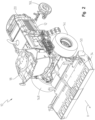
Fig. 1 is a side front perspective view of an agricultural machine including a mower implement positioned at a front end of the agricultural machine; -
Fig. 2 is a side front perspective view of an agricultural machine including a mower-conditioner implement positioned at a front end of the agricultural machine; -
Fig. 3 is a perspective view of an impeller drive assembly, which may be included in the mower-conditioner implement ofFig. 2 ; -
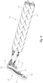
Fig. 4 is a perspective view of a roll conditioning drive assembly, which may be included in the mower-conditioner implement ofFig. 2 ; -
Fig. 5 is a diagrammatic view of a flexible drive assembly for the mower implement ofFig. 1 including a drive belt, a drive roller, a flex roller movable relative to the drive roller, and a spring coupled to the flex roller; -
Fig. 6 is a diagrammatic view of a flexible drive assembly for the mower-conditioner implement ofFig. 2 including a drive belt, a drive roller, a driven roller, a flex roller positioned outside the drive belt and movable relative to the drive roller, and a spring coupled to the flex roller; -
Fig. 7 is a diagrammatic view of a flexible drive assembly similar toFig. 6 , where instead the flex roller is positioned inside the drive belt; -
Fig. 8 is a diagrammatic view of a flexible drive assembly similar toFig. 7 , where instead the drive belt has been replaced by a metallic chain and the spring has been replaced by a linear actuator; and -
Fig. 9 is a perspective view of a control system including a crop load sensor operatively coupled to a controller. - Corresponding reference numerals are used to indicate corresponding parts throughout the several views.
- The embodiments of the present disclosure described below are not intended to be exhaustive or to limit the disclosure to the precise forms in the following detailed description. Rather, the embodiments are chosen and described so that others skilled in the art may appreciate and understand the principles and practices of the present disclosure.
- Referring to
Fig. 1 , anagricultural machine 10 is shown and is operable to mow crop in a field. Theagricultural machine 10 includes amain frame 12 supported on right and leftfront wheels rear wheel 16L is shown. Theagricultural machine 10 also includes acab 18 carried on a forward region of themain frame 12 and ahousing 20 illustratively shown as being positioned reward of thecab 18. A power source such as an internal combustion engine may be positioned in thehousing 20. As shown inFig. 1 , theagricultural machine 10 includes amower implement 22, which may be referred to as a draper, coupled to and supported by the forward end of themain frame 12. Operator controls are provided in thecab 18 for operation of theagricultural machine 10, including the attached mower implement 22. - The
mower implement 22 includes a laterally extendingframe 24 that extends perpendicular to a fore-and-aft harvesting direction of travel "V" of theagricultural machine 10. Themower implement 22 further includes an elongatereciprocating knife 26 that extends across a width of the mower implement 22. This reciprocatingknife 26 is disposed immediately in front of a harvested crop conveyor assembly. In the illustrative embodiment, the crop conveyor assembly includes aright side conveyor 28 that carries harvested crop from the right side of the mower implement 22 to a central region of the mower implement 22, aleft side conveyor 30 that carries crop from the left side of the mower implement 22 to the central region of the mower implement 22, and acentral conveyor 32 that receives crop from theleft side conveyor 30 and theright side conveyor 28, and conveys the harvested crop rearward. In the illustrative embodiment, each of the three conveyors is a conveyor with an endless belt rotated by rollers, which may be referred to as a flexible drive assembly. Moreover, the endless belt is an example of an endless loop and may be referred to as such herein. The components and arrangement of flexible drive assemblies are described in greater detail below; however, it should be appreciated that the left sideflexible drive assembly 30 and the right sideflexible drive assembly 28 are identical (yet mirror images of each other) such that description of one applies equally to the other. The description related to theflexible drive assembly 30 may also applied to theflexible drive assembly 32. - The implement of the
agricultural machine 10 could take many configurations in addition to that described with regard toFig. 1 . For example, as shown inFig. 2 , the implement of theagricultural machine 10 may be embodied as a mower-conditioner implement 34. It should be appreciated that the mower implement 22 and the mower-conditioner implement 34 may be collectively referred to as crop cutting implements. As shown inFig. 3 , the mower-conditioner implement 34 may include an impeller 36 (e.g., an elongated roll) with a plurality oftines 38 used to scrape harvested crop from cutting blades to shorten drying time of the crop. As shown inFig. 4 , the mower-conditioner implement 34 may otherwise include a roll conditioner 40 (e.g., a pair ofcylindrical rolls 42 coupled together indirectly via a plurality ofgears 44 arranged in a gear box 46), which is used to crimp crop stems to shorten drying time and mitigate exposure to environmental elements. - In any event, as shown in
Fig. 2 , the mower-conditioner implement 34 includes a laterally extendingframe 50 that extends perpendicular to a fore-and-aft harvesting direction of travel "V" of theagricultural machine 10. In the illustrative embodiment shown inFigs. 3-4 , the mower-conditioner implement 34 includes aflexible drive assembly 48, the components and arrangement of which will be described in greater detail below. - It has been discovered that while differences exist between certain flexible drive assemblies (e.g., 30 and 48) of various mower or mower-conditioner implements, an increased drive torque (resulting in increased belt/chain force) is required when crop throughput to the implement increases; it has also been discovered that despite differences in the components and arrangement of various flexible drive assemblies, universally applicable systems and methods can be used to quantify the crop harvested by the agricultural machine. The systems and methods are described in further detail below.
- Referring now to
Fig. 5 , theflexible drive assembly 30 is shown in a diagrammatic view. In the illustrative embodiment, theflexible drive assembly 30 includes adrive roller 52, aflex roller 54, and anendless loop 56. Theendless loop 56 is also shown inFig. 1 . Thedrive roller 52 may be driven directly or indirectly by a hydraulic pump, an electric motor, an internal combustion engine, or the like. In the illustrative embodiment, theendless loop 56 is a belt formed of elastomeric material; however, in other embodiments the elastomeric belt may be replaced with a metallic mesh or any other material suitable for conveying crop along theflexible drive assembly 30. It should be appreciated that for theflexible drive assembly 30 theendless loop 56 is configured to engage with (i.e., support and convey) the harvested crop; however unlike a baler belt, for example, theendless loop 56 does not compact harvested crop to form a bale. - Referring still to
Fig. 5 , thedrive roller 52 is centered on adrive roller axis 58 about which thedrive roller 52 rotates. Thedrive roller axis 58 is fixed relative to theframe 24 of the mower implement 22. In some embodiments, thedrive roller 52 may rotate about a pin or bore that is positioned along thedrive roller axis 58 and coupled directly or indirectly to theframe 24 of the mower implement 22. Theflex roller 54 is centered on aflex roller axis 60 about which theflex roller 54 rotates. Theflex roller axis 60 is movable relative to theframe 24 of the mower implement 22; therefore, theflex roller axis 60 is movable relative to thedrive roller axis 58 as well. In some embodiments, theflex roller 54 may rotate about a pin or bore that is positioned along theflex roller axis 60 and coupled directly or indirectly to theframe 24 of the mower implement 22. As shown inFig. 5 , theendless loop 56 contacts thedrive roller 52 and theflex roller 54 such that rotation of thedrive roller 52 drives rotation of theendless loop 56 thereby driving rotation of theflex roller 54. - As suggested by
Fig. 5 , in theflexible drive assembly 30, thedrive roller 52 and theflex roller 54 are each positioned within theendless loop 56. Additionally, in the illustrative embodiment, thedrive roller axis 58 and theflex roller axis 60 are parallel to each other. - In some embodiments, the mower implement 22 further includes a device configured to resist movement of the
flex roller axis 60. It should be appreciated that "resisting" movement, as the term is used herein, does not prevent movement; it merely makes it more difficult. To illustrate, as additional crop is accumulated atop theendless loop 56, the drive torque required to the rotateendless loop 56 at the same speed increases. This causes an increase in the tension of theendless loop 56, which causes movement of the flex roller 54 (and the flex roller axis 60) toward to thedrive roller 52. In the illustrative embodiment shown inFig. 5 , the device configured to resist movement of theflex roller axis 60 is aspring 62. As shown inFig. 5 , thespring 62 includes afirst end 64 fixed relative to the drive roller axis 58 (and relative to the frame 24) and asecond end 66 movable relative to the drive roller axis 58 (and relative to the frame 24). As a result, the length of thespring 62 varies with movement of theflex roller axis 60 relative to the drive roller axis 58 (and relative to the frame 24). - In other embodiments, the
spring 62 coupled to theflexible drive assembly 30 may be replaced with a linear actuator 68 (seeFig. 8 ) or another suitable device for resisting movement of theflex roller axis 60. Thespring 62 andlinear actuator 68 may be descriptively referred to herein as retractable linear devices based on their structure. Thelinear actuator 68 will be described in greater detail with regard toFig. 8 . - Another
flexible drive assembly 48 is shown inFigs. 3 ,4 , and6 . In the illustrative embodiment, theflexible drive assembly 48 includes adrive roller 70, aflex roller 72, and anendless loop 74. Thedrive roller 70 may be driven directly or indirectly by a hydraulic pump, an electric motor, an internal combustion engine, or the like. In the illustrative embodiment, theendless loop 74 is a belt formed of elastomeric material; however, in other embodiments the elastomeric belt may be replaced with a metallic mesh or any other material suitable for operating in theflexible drive assembly 48. It should be appreciated that for theflexible drive assembly 48 theendless loop 74 does not engage with the harvested crop; thus, unlike a baler belt, for example, theendless loop 74 does not compact harvested crop to form a bale. - Referring still to
Figs. 3 ,4 , and6 , thedrive roller 70 is centered on adrive roller axis 76 about which thedrive roller 70 rotates. Thedrive roller axis 76 is fixed relative to theframe 50 of the mower-conditioner implement 34. In some embodiments, thedrive roller 70 may rotate about a pin or bore that is positioned along thedrive roller axis 76 and coupled directly or indirectly to theframe 50 of the mower-conditioner implement 34. As shown inFig. 6 , theflex roller 72 is centered on aflex roller axis 78 about which theflex roller 72 rotates. Theflex roller axis 78 is movable relative to theframe 50 of the mower-conditioner implement 34; therefore, theflex roller axis 78 is movable relative to thedrive roller axis 76 as well. In some embodiments, theflex roller 72 may rotate about a pin or bore that is positioned along theflex roller axis 78 and coupled directly or indirectly to theframe 50 of the mower-conditioner implement 34. As shown inFigs. 3 ,4 , and6 , theendless loop 74 contacts thedrive roller 70 and theflex roller 72 such that rotation of thedrive roller 70 drives rotation of theendless loop 74 thereby driving rotation of theflex roller 72. - Referring still to
Figs. 3 ,4 , and6 , theflexible drive assembly 48 further includes a drivenroller 80. As shown inFig. 6 , the drivenroller 80 is centered on a drivenroller axis 82 about which the drivenroller 80 rotates. The drivenroller axis 82 is fixed relative to theframe 50 of the mower-conditioner implement 34; therefore, the drivenroller axis 82 is fixed relative to thedrive roller axis 76 as well. In some embodiments, the drivenroller 80 may rotate about a pin or bore that is positioned along the drivenroller axis 82 and coupled directly or indirectly to theframe 50 of the mower-conditioner implement 34. As shown inFigs. 3 ,4 , and6 , theendless loop 74 contacts thedrive roller 70 and the drivenroller 80 such that rotation of thedrive roller 70 drives rotation of theendless loop 74 thereby driving rotation of the drivenroller 80. InFigs. 3 and6 , the drivenroller 80 is coupled to theimpeller 36 to drive rotation of theimpeller 36. It should be appreciated that in other embodiments the drivenroller 80 may be coupled to the plurality ofgears 44 to drive rotation thereof, which drives rotation of the oppositely rotating rolls 42. - As suggested by
Figs. 3 ,4 , and6 , in theflexible drive assembly 48, thedrive roller 70 and the drivenroller 80 are positioned within theendless loop 74, yet theflex roller 72 is positioned outside theendless loop 74. Additionally, in the illustrative embodiment, thedrive roller axis 76, theflex roller axis 78, and the drivenroller axis 82 are parallel to each other. - Referring now to
Fig. 6 (and also shown inFig. 3 ), theagricultural machine 10 further includes abracket 84 having afirst portion 86, asecond portion 88, and athird portion 90. In the illustrative embodiment, thefirst portion 86 of thebracket 84 is directly coupled to theflex roller 72. Thesecond portion 88 of thebracket 84 is directly coupled to a retractable linear device, which is embodied as thespring 62 inFigs. 3 and6 ; however, it should be appreciated that the retractable linear device could also be embodied as the linear actuator 68 (seeFig. 8 ) or another suitable device for resisting movement of theflex roller axis 78. In the illustrative embodiment, thesecond portion 88 of thebracket 84 is coupled to thesecond end 66 of thespring 62. Thus, thesecond end 66 of thespring 62 is movable relative to the drive roller axis 76 (and relative to the frame 50), and thefirst end 64 of thespring 62 is fixed relative to the drive roller axis 76 (and relative to the frame 50). Thethird portion 90 of thebracket 84 includes apivot axis 92 passing therethrough. Thebracket 84 is pivotably coupled to theframe 50 at thepivot axis 92 such that thebracket 84 may pivot relative to theframe 50 as theflex roller axis 78 moves relative to theframe 50. - Another
flexible drive assembly 94 is shown inFig. 7 . The same reference numbers are used to describe like components of theflexible drive assemblies drive assemblies flexible drive assembly 94, theflex roller 72 is positioned inside theendless loop 74. InFig. 7 (likeFig. 4 ), the drivenroller 80 is coupled to the plurality ofgears 44 to drive their rotation, which drives rotation of the oppositely rotating rolls 42. It should be appreciated that in other embodiments the drivenroller 80 is coupled to theimpeller 36 to drive its rotation. Similar to theflexible drive assembly 48, in theflexible drive assembly 94, theendless loop 74 does not engage with the harvested crop; therefore, unlike a baler belt, for example, theendless loop 74 does not compact harvested crop to form a bale. - Another
flexible drive assembly 96 is shown inFig. 8 The same reference numbers are used to describe like components of theflexible drive assemblies drive assemblies flexible drive assembly 96, theendless loop 98 is embodied as a metallic chain. - Also, as shown in
Fig. 8 , thelinear actuator 68 may include ahollow rod 102 and apiston 104 configured to extend and retract relative to thehollow rod 102. In the illustrative embodiment, thehollow rod 102 is fixed relative to the drive roller axis 76 (and the frame 50) and thepiston 104 is movable relative to the drive roller axis 76 (and the frame 50); however, in some embodiments, the arrangement of thepiston 104 and thehollow rod 102 may be reversed. - As shown in
Fig. 9 , theagricultural machine 10 further includes at least onecrop load sensor 100A-E configured to measure a characteristic of theagricultural machine 10 associated with the quantity (or load) of harvested crop being processed by theflexible drive assembly Fig. 6 ), acrop load sensor 100A directly measures a change in location of theflex roller axis 78 relative to thedrive roller axis 76. This is because movement of a flex roller axis relative to a drive roller axis results from a change in tension of an endless loop, which results from a change in the quantity of harvested crop being processed by the flexible drive assembly. As shown inFig. 6 , thecrop load sensor 100A may be a proximity sensor positioned, for example, on a bore or pin aligned with thedrive roller axis 76. The proximity sensor may be used with a target (as is known in the art), which is illustratively located on a bore or pin aligned with theflex roller axis 78. In other embodiments, any other suitable sensor may be used to measure movement of a flex roller (or a component that moves therewith) relative to a portion of acorresponding frame 24, 50 (or any component fixed relative to theframe 24, 50). - In other embodiments, at least one crop load sensor (100B-E) is configured to measure a characteristic of the
agricultural machine 10 that is a proxy for the change in location of a flex roller axis relative to a drive roller axis. For example, as suggested byFig 5 ., thecrop load sensor 100B is configured to measure the tension of thespring 62, given a known spring length and known spring constant. In other embodiments, as shown inFig. 8 , thecrop load sensor 100D is configured to measure the pressure of thelinear actuator 68. In other embodiments, as shown inFig. 7 , the crop load sensor 100C is configured to measure the degree of rotation of the bracket 84 (about its pivot axis 92) relative to theframe 50. In other embodiments, a crop load sensor 100 E may be configured to measure a change in the length of a retractable linear device. Each of these measurement are characteristics of theagricultural machine 10 associated with the quantity of harvested crop being processed by theflexible drive assembly crop load sensors 100A-E are described with respect to specific embodiments, eachcrop load sensor 100A-E may be applicable to the other embodiments described herein. - Referring again to
Fig. 9 , a diagrammatic view of acontrol system 200 of theagricultural machine 10 is shown. Thecontrol system 200 includes acontroller 202 having a memory and a processor configured to execute instructions (i.e., algorithmic steps) stored on the memory. Thecontroller 202 may be a single controller or a plurality of controllers operatively coupled to one another. Thecontroller 202 may be housed by theagricultural machine 10 or positioned remotely, away from theagricultural machine 10. Thecontroller 202 may be hardwired or connected wirelessly to other components of theagricultural machine 10 via Wi-Fi, Bluetooth, or other known means of wireless communication. - As suggested by
Fig. 9 , thecontroller 202 is operatively coupled to thecrop load sensor 100A-E and configured to receive a signal from the at least onecrop load sensor 100A-E indicative of the measured characteristic of theagricultural machine 10 associated with the quantity of harvested crop being processed by theflexible drive assembly controller 202 is configured to determine the quantity of harvested crop being processed by theflexible drive assembly agricultural machine 10. More specifically, in terms of an algorithm, thecontroller 202 may multiply a measured value (e.g., (i) a tension of a retractable linear device, (ii) a pressure of a retractable linear device, (iii) a length of a retractable linear device, (iv) a degree of rotation of a bracket relative to a frame, or (v) a location of a flex roller relative to a portion of a frame or other component fixed relative to the frame) by a predetermined constant, e.g., a value stored in the memory, to determine the quantity of harvested crop processed by the mower or mower-conditioner implement 22, 34. - The
controller 202 may be operatively coupled to auser interface 204 and configured to receive input data from the user via auser interface 204 such as the predetermined constant. Moreover, thecontroller 202 may output data to theuser interface 204 such as the determined quantity of crop processed by the mower or mower-conditioner implement 22, 34. - While this disclosure has been described with respect to at least one embodiment, the present disclosure can be further modified within the spirit and scope of this disclosure. This application is therefore intended to cover any variations, uses, or adaptations of the disclosure using its general principles. Further, this application is intended to cover such departures from the present disclosure as come within known or customary practice in the art to which this disclosure pertains and which fall within the limits of the appended claims.
Claims (15)
- An agricultural machine (10) capable of sensing a harvested crop load, comprising:a crop cutting implement (22, 34) including a frame (24, 50) and a flexible drive assembly (30, 48, 94, 96) supported by the frame, the flexible drive assembly including:a drive roller (52, 70) configured to rotate about a drive roller axis (58, 76) that is fixed relative to the frame,a flex roller (54, 72) that is driven by the drive roller to rotate about a flex roller axis (60, 78) that is movable relative to the drive roller axis; andan endless loop (56, 74, 98) contacting the drive roller and the flex roller to drive rotation of the flex roller about the flex roller axis;a retractable linear device (62, 68) including a first end (64, 102) fixed relative to the frame and a second end (66, 104) movable relative to the frame, wherein the retractable linear device is configured to resist movement of the flex roller axis relative to the drive roller axis; anda crop load sensor (100A-E) configured to measure a characteristic of the agricultural machine associated with the quantity of harvested crop being processed by the flexible drive assembly.
- The agricultural machine of claim 1, further comprising:a controller (202) operatively coupled to the crop load sensor and configured to receive a signal from the crop load sensor indicative of the measured characteristic of the agricultural machine;wherein the controller is configured to determine the quantity of harvested crop being processed by the flexible drive assembly based on the signal indicative of the measured characteristic of the agricultural machine.
- The agricultural machine of claim 1 or 2, wherein the retractable linear device is a spring (62); and wherein the crop load sensor (100B) is configured to measure the tension of the spring.
- The agricultural machine according to at least one of the preceding claims, wherein the retractable linear device is a linear actuator (68) including a hollow rod (102) and a piston (104) configured to extend and retract relative to the hollow rod; and wherein the crop load sensor (100D) is configured to measure the pressure of the linear actuator.
- The agricultural machine according to at least one of the preceding claims, wherein the flexible drive assembly further includes a driven roller (80) positioned inside the endless loop and rotatably driven by the endless loop about a driven roller axis (82) that is fixed relative to the drive roller axis.
- The agricultural machine according to at least one of the preceding claims, wherein the flex roller (78) is positioned outside of the endless loop (74).
- The agricultural machine according to at least one of the preceding claims, wherein the flex roller is rotatably coupled to a first portion (86) of a bracket (84); and wherein the second end of the retractable linear device is coupled to a second portion (88) of the bracket.
- The agricultural machine according to at least one of the preceding claims, wherein the bracket is pivotably coupled to the frame at a pivot axis (92) of the bracket passing through a third portion (90) of the bracket.
- The agricultural machine according to at least one of the preceding claims, wherein the crop load sensor (100C) is configured to measure the degree of rotation of the bracket about the pivot axis.
- The agricultural machine according to at least one of the preceding claims, wherein the flex roller is positioned inside of the endless loop.
- The agricultural machine according to at least one of the preceding claims, wherein the crop load sensor (100A) is configured to measure the distance between the flex roller and a portion of the frame or a component fixedly coupled thereto.
- The agricultural machine according to at least one of the preceding claims, wherein the endless loop does not compact the harvested crop.
- The agricultural machine according to at least one of the preceding claims, wherein the endless loop (74, 98) does not engage with the harvested crop.
- The agricultural machine according to at least one of the preceding claims, wherein the crop cutting implement further includes:an elongated roll (36) rotationally driven by the drive roller (70) via the endless loop (74, 98); anda plurality of tines (38) extending from the elongated roll and configured to engage with the harvested crop.
- The agricultural machine according to at least one of the preceding claims, wherein the crop cutting implement further includes:a pair of oppositely rotating elongated rolls (42) that are configured to engage with the harvested crop; anda plurality of gears (44) rotationally driven by the drive roller (70) via the endless loop (74, 98) and coupled to the pair of oppositely rotating elongated rolls to cause rotation thereof.
Applications Claiming Priority (1)
| Application Number | Priority Date | Filing Date | Title |
|---|---|---|---|
| US17/739,359 US20230354746A1 (en) | 2022-05-09 | 2022-05-09 | Crop quantity sensing system and method for a mower drive assembly |
Publications (1)
| Publication Number | Publication Date |
|---|---|
| EP4275473A1 true EP4275473A1 (en) | 2023-11-15 |
Family
ID=86330427
Family Applications (1)
| Application Number | Title | Priority Date | Filing Date |
|---|---|---|---|
| EP23172004.6A Pending EP4275473A1 (en) | 2022-05-09 | 2023-05-08 | Crop quantity sensing system and method for a mower drive assembly |
Country Status (2)
| Country | Link |
|---|---|
| US (1) | US20230354746A1 (en) |
| EP (1) | EP4275473A1 (en) |
Citations (5)
| Publication number | Priority date | Publication date | Assignee | Title |
|---|---|---|---|---|
| EP0958729A1 (en) * | 1998-05-22 | 1999-11-24 | New Holland Belgium N.V. | Harvester with crop flow rate sensor |
| US20020187819A1 (en) * | 1999-06-30 | 2002-12-12 | Shinners Kevin J. | Yield monitor for forage crops |
| EP1862056A1 (en) * | 2006-05-30 | 2007-12-05 | CNH Belgium N.V. | Combine cleaning fan control system |
| EP3146833A1 (en) * | 2015-09-28 | 2017-03-29 | CLAAS Selbstfahrende Erntemaschinen GmbH | Agricultural work machine |
| EP3461316A1 (en) * | 2017-09-28 | 2019-04-03 | Deere & Company | Methods and apparatus to sense the weight of grain in a grain elevator |
Family Cites Families (7)
| Publication number | Priority date | Publication date | Assignee | Title |
|---|---|---|---|---|
| US4130980A (en) * | 1977-01-06 | 1978-12-26 | International Harvester Company | Combine automatic travel control system |
| US6213870B1 (en) * | 1999-03-24 | 2001-04-10 | Caterpillar Inc. | Stall prevention system |
| US6475081B2 (en) * | 2001-03-20 | 2002-11-05 | Deere & Company | Throughput control for combines having a variable torque sensing drive |
| GB0721909D0 (en) * | 2007-11-08 | 2007-12-19 | Cnh Belgium Nv | Apparatus and method for controlling the speed of a combine harvester |
| DE102014219049B4 (en) * | 2014-09-22 | 2024-07-11 | Deere & Company | Forage harvester with reversible conditioning device |
| GB2560998A (en) * | 2017-03-31 | 2018-10-03 | Kverneland Group Kerteminde As | Continuously variable conditioner speed |
| DE102018106915A1 (en) * | 2018-03-23 | 2019-09-26 | Claas Selbstfahrende Erntemaschinen Gmbh | Forage |
-
2022
- 2022-05-09 US US17/739,359 patent/US20230354746A1/en active Pending
-
2023
- 2023-05-08 EP EP23172004.6A patent/EP4275473A1/en active Pending
Patent Citations (5)
| Publication number | Priority date | Publication date | Assignee | Title |
|---|---|---|---|---|
| EP0958729A1 (en) * | 1998-05-22 | 1999-11-24 | New Holland Belgium N.V. | Harvester with crop flow rate sensor |
| US20020187819A1 (en) * | 1999-06-30 | 2002-12-12 | Shinners Kevin J. | Yield monitor for forage crops |
| EP1862056A1 (en) * | 2006-05-30 | 2007-12-05 | CNH Belgium N.V. | Combine cleaning fan control system |
| EP3146833A1 (en) * | 2015-09-28 | 2017-03-29 | CLAAS Selbstfahrende Erntemaschinen GmbH | Agricultural work machine |
| EP3461316A1 (en) * | 2017-09-28 | 2019-04-03 | Deere & Company | Methods and apparatus to sense the weight of grain in a grain elevator |
Also Published As
| Publication number | Publication date |
|---|---|
| US20230354746A1 (en) | 2023-11-09 |
Similar Documents
| Publication | Publication Date | Title |
|---|---|---|
| EP4042848B1 (en) | Radio frequency identification (rfid) sensor network for a work machine | |
| AU2020371706B2 (en) | Controlled lateral belt reverse for draper head of agricultural combine | |
| CA3175437A1 (en) | Agricultural machines and methods for controlling windrow properties | |
| EA029020B1 (en) | Mower-conditioner header speed control based on forward travel speed | |
| US11304370B2 (en) | Reversible compression auger on harvesting header | |
| US20240138302A1 (en) | Automatic setting of header floatation on self-propelled windrower | |
| US20070113533A1 (en) | Feeding device for a field chopper | |
| US8516957B1 (en) | Measuring distance for bale size in a round baler | |
| EP4029358B1 (en) | Radio frequency identification (rfid) sensor network for a work machine | |
| US8935979B2 (en) | Even bale block for monitoring bale shape in a round baler | |
| US20230354746A1 (en) | Crop quantity sensing system and method for a mower drive assembly | |
| US10750669B2 (en) | Round baler, combination of an agricultural vehicle with such a baler and method for forming round bales | |
| US12408592B2 (en) | Agricultural baler system with bale stall identification | |
| US5182987A (en) | Round baler with tracking control for traction means used to move crop for baling | |
| US12426536B2 (en) | Center pivot mower system with end of row mower adjustment | |
| US20250143215A1 (en) | Method for field working | |
| NL2014462A (en) | Apparatus and method for picking up loose crop material and conveying it through a feeding channel. | |
| US20250374859A1 (en) | Crop Conditioning | |
| US20230309456A1 (en) | Floating rotor and auger arrangement of agricultural baler | |
| US20250204313A1 (en) | Crop Conditioning | |
| US20250204325A1 (en) | Crop Conditioning | |
| US20250204316A1 (en) | Crop Conditioning | |
| US7398144B2 (en) | Apparatus and method to calibrate the PTO with the disk or sickle of an agricultural windrower | |
| US20240049639A1 (en) | Actively variable swath gate position | |
| US20230403980A1 (en) | Variable speed conditioner rolls for mower-conditioner |
Legal Events
| Date | Code | Title | Description |
|---|---|---|---|
| PUAI | Public reference made under article 153(3) epc to a published international application that has entered the european phase |
Free format text: ORIGINAL CODE: 0009012 |
|
| STAA | Information on the status of an ep patent application or granted ep patent |
Free format text: STATUS: THE APPLICATION HAS BEEN PUBLISHED |
|
| AK | Designated contracting states |
Kind code of ref document: A1 Designated state(s): AL AT BE BG CH CY CZ DE DK EE ES FI FR GB GR HR HU IE IS IT LI LT LU LV MC ME MK MT NL NO PL PT RO RS SE SI SK SM TR |
|
| STAA | Information on the status of an ep patent application or granted ep patent |
Free format text: STATUS: REQUEST FOR EXAMINATION WAS MADE |
|
| 17P | Request for examination filed |
Effective date: 20240515 |
|
| RBV | Designated contracting states (corrected) |
Designated state(s): AL AT BE BG CH CY CZ DE DK EE ES FI FR GB GR HR HU IE IS IT LI LT LU LV MC ME MK MT NL NO PL PT RO RS SE SI SK SM TR |