EP3146833A1 - Agricultural work machine - Google Patents
Agricultural work machine Download PDFInfo
- Publication number
- EP3146833A1 EP3146833A1 EP16176869.2A EP16176869A EP3146833A1 EP 3146833 A1 EP3146833 A1 EP 3146833A1 EP 16176869 A EP16176869 A EP 16176869A EP 3146833 A1 EP3146833 A1 EP 3146833A1
- Authority
- EP
- European Patent Office
- Prior art keywords
- belt
- drive
- machine control
- work machine
- machine
- Prior art date
- Legal status (The legal status is an assumption and is not a legal conclusion. Google has not performed a legal analysis and makes no representation as to the accuracy of the status listed.)
- Granted
Links
Images

Classifications
-
- A—HUMAN NECESSITIES
- A01—AGRICULTURE; FORESTRY; ANIMAL HUSBANDRY; HUNTING; TRAPPING; FISHING
- A01D—HARVESTING; MOWING
- A01D69/00—Driving mechanisms or parts thereof for harvesters or mowers
- A01D69/06—Gearings
-
- A—HUMAN NECESSITIES
- A01—AGRICULTURE; FORESTRY; ANIMAL HUSBANDRY; HUNTING; TRAPPING; FISHING
- A01D—HARVESTING; MOWING
- A01D41/00—Combines, i.e. harvesters or mowers combined with threshing devices
- A01D41/12—Details of combines
- A01D41/127—Control or measuring arrangements specially adapted for combines
- A01D41/1274—Control or measuring arrangements specially adapted for combines for drives
-
- A—HUMAN NECESSITIES
- A01—AGRICULTURE; FORESTRY; ANIMAL HUSBANDRY; HUNTING; TRAPPING; FISHING
- A01D—HARVESTING; MOWING
- A01D43/00—Mowers combined with apparatus performing additional operations while mowing
- A01D43/08—Mowers combined with apparatus performing additional operations while mowing with means for cutting up the mown crop, e.g. forage harvesters
- A01D43/085—Control or measuring arrangements specially adapted therefor
Definitions
- the present invention relates to an agricultural work machine according to the preamble of claim 1.
- the agricultural work machine in question may be any agricultural work machine equipped with a machine control and at least one belt drive for transmitting drive power.
- These include, for example, tractors, especially tractors, self-propelled harvesters, especially forage harvesters, combine harvester o. The like ..
- this term does not include self-propelled attachments and the combination of the respective tractor with the attachment.
- the agricultural machine ( GB 911,361 A ), from which the invention proceeds, is equipped with a drive arrangement and a plurality of the drive arrangement downstream drive components such as a traction drive, an inclined conveyor or a threshing drum of a combine harvester.
- the drive technology coupling between the drive assembly and the work organs is provided at least partially via belt drives.
- the feeder conveyor is assigned a monitoring device which detects the continuous crop based on the deflection of a carrier of the feederhouse. Based on this acquisition, the machine control activates the travel drive.
- This solution for monitoring the relevant work organ which basically also provides information about the transmitted by means of the belt drive power is structurally complex and tailored to the particular working organ, so that the resulting cost is relatively high.
- the invention is based on the problem to design the known agricultural machine such and further, that their control and / or monitoring is optimized in particular taking into account the transmitted mechanical drive power with simple means.
- Essential is the fundamental consideration that even complex machines with a plurality of belt drives can be controlled and / or monitored in a structurally simple and cost-effective manner by supplying the machine control during operation with a belt extension signal of the relevant drive belt. It has been further recognized that can be concluded from this dynamic belt extension signal, which is due to the load-dependent expansion of the respective drive belt, easily on the output and / or recorded drive power. With a suitable design of the drive belt can be spoken at a constant input speed and neglecting losses such as slippage, friction o. The like. Proportionality between the dynamic belt elongation and the output or recorded drive power, which makes the evaluation very simple.
- the relevant belt drive initially has a belt tensioner which deflects depending on the belt elongation and has a belt expansion sensor.
- the belt expansion sensor determines the deflection of the belt tensioner.
- the machine control then takes over the control and / or monitoring of the working machine during the working operation based on the at least one belt extension signal and a characteristic set associated with the belt drive.
- the characteristic value set takes into account the fact that the mechanical properties of the respective drive belt are different depending on its design, which must be taken into account by the machine control in the control or monitoring of the working machine.
- the dynamic belt elongation signal is in the foreground, which results during the working operation of the working machine.
- the dynamic belt extension signal results from the transmitted via the drive belt driving force, which leads via the modulus of elasticity of the drive belt to a corresponding strain.
- the belt tensioner can be made passive and then is usually spring biased by a spring arrangement on the drive belt.
- the belt tensioner can also be designed actively and, if appropriate in addition to a spring arrangement, act with a drive on the drive belt. In such a case, it must again be taken into consideration that a certain belt elongation can also be due to the drive of the belt tensioner, which can be taken into account, for example, via further correction factors.
- the drive technology coupling between the drive assembly and a working member may be provided via a belt drive or via a plurality of drive technology successively connected belt drives. Furthermore, a plurality of belt drives can branch off from the drive arrangement in parallel drive trains. This shows the scalability of the proposed solution by one and the same measuring principle, namely the determination of the dynamic belt elongation, almost unchanged on different belt drives can be implemented without the measurement arrangement must be changed. This is the subject of the preferred embodiment of claim 2.
- the belt elongation sensor is designed as an angle sensor which is associated with a rocker of the belt tensioner.
- a rocker of the belt tensioner is preferably a tension roller, which rolls on the drive belt.
- Such an angle sensor can be attached in a particularly simple manner to the respective belt tensioner. In particular, a simple retrofitting of existing agricultural machines is possible here.
- the use of the belt extension signal by the machine control can be done in quite different ways. According to claim 5, it may be advantageous to generate from the belt extension signal and the set of characteristic values the transmitted drive power or the transmitted drive power. However, it is also conceivable that only a theoretical comparison value is generated from the belt elongation signal and the characteristic value set, from which the power consumption of the different working organs can be compared.
- the further preferred embodiments according to claims 6 to 8 relate to the calibration of the belt elongation sensors in order to adapt the respective set of characteristic values to the conditions actually prevailing on the working machine. This is primarily about the determination or adaptation of the relationship between the deflection of the belt tensioner and the transmitted drive power and / or the transmitted drive power. On the one hand, the necessity of such a calibration results from the fact that each drive belt has a certain run-in behavior, in which a certain plastic strain sets in. Further plastic strain occurs in a later life cycle phase of the drive belt, which is primarily due to wear of the drive belt.
- the machine control uses the belt extension signal to implement a user selectable operating strategy.
- the operating strategy may be, for example, the requirement to minimize the power consumption of a particular work organ.
- the further preferred embodiments according to claims 11 to 14 relate to the monitoring of the working machine based on the proposed belt extension signal.
- An increase in the machine service life can be increased in the issue of wear information according to claim 11 or a maintenance message according to claim 13 in an uncomplicated manner.
- an emergency function is realized such that the machine control switches off the drive assembly at a maximum expansion, which regularly precedes a rupture of the drive belt.
- the actual rupture of the drive belt which manifests itself in a maximum deflection of the belt tensioner, lead to the shutdown of the drive assembly.
- the term "agricultural work machine” is to be understood comprehensively. In the illustrated embodiment, it is in the proposed agricultural machine 1 to a forage harvester. All versions of the forage harvester apply to all other types of agricultural machinery, especially for a combine harvester, accordingly.
- the agricultural working machine 1 is equipped with a machine control 2, which takes over the control and / or monitoring of the working machine 1.
- the work machine 1 is further equipped with work organs 3-6, which are driven by a drive assembly 7.
- the working machine 1 here initially has a pre-press unit 3, which acts as a feed device for the crop.
- the pre-press unit 3 is provided with two pairs of pre-press rollers 3b-e forming a press channel 3a.
- the front pre-press rolls 3b, 3c take over a pre-compaction of the picked crop, while the rear pre-press rolls 3d, 3e take over a uniform compaction and a further transport of the crop.
- the working machine 1 For chopping the picked crop, the working machine 1 as a further working organ on a chopper 4, to which in turn another working organ a conveyor 5 for the transport of chopped crop in an ejection channel 8 connects.
- the chopper 9 has a knife drum 9a.
- the proposed working machine 1 is further equipped with a traction drive 6 as another working member, which is here and preferably a hydraulic drive.
- the drive assembly 7 is coupled via at least one belt drive 9, 10 with at least one working member 3-6 drive technology.
- the belt drive 9 serves the drive-technical coupling of the drive arrangement 7 with the cutterhead 4a and the conveyor device 5.
- the further belt drive 10, the in Fig. 1 is merely indicated, the drive-technical coupling of the drive assembly 7 is used with the drive 6 or with an associated hydraulic pump system.
- Other belt drives are conceivable here, for example for driving the pre-press unit or the like.
- the belt drive 9 has a drive roller 11, here and preferably a plurality of output rollers 12, 13 and a drive belt 14. In doing so, the in Fig. 1 lower portion of the drive belt 14, the Switzerlandtrum 15 and the upper portion of the drive belt 14 is the Lostrum 16.
- the operating direction of the drive belt 14 is shown in the drawing by arrows.
- the belt drive 9 has a depending on the belt elongation deflecting belt tensioner 17 with a belt strain sensor 18 which determines the deflection of the belt tensioner 17 to generate a belt extension signal 19.
- the further belt drive 10 likewise has a belt tensioner 20 with a corresponding belt elongation sensor 21, which determines the deflection of the belt tensioner 20 in order to generate a belt extension signal 22.
- the machine control 2 activates and / or monitors the working machine 1 during working operation based on the belt extension signal 19 and a characteristic value set assigned to the belt drive 9.
- the belt extension signal 19 are applicable to the belt elongation signal 22.
- the proposed solution can be applied to virtually any working member 3-6 or any group of working members 3-6 driven by a belt drive 9.
- identical belt tensioners 17, 20 with identical belt elongation sensors 18, 21 are used for all belt drives 9, 10, which enables cost-effective control or monitoring of even complex working machines 1.
- the drive arrangement 7 is correspondingly drive-coupled via at least two belt drives 9, 10 with working members 3-6, in that a corresponding belt extension signal 19 can be generated for each belt drive.
- the machine controller 2 is provided with the above-mentioned parameter set, which preferably contains information on the expansion behavior of the relevant drive belt 14, here and preferably an modulus of elasticity (modulus of elasticity) of the relevant drive belt 14, covers.
- the parameter set comprises a relationship between the deflection of the belt tensioner 17 and the drive force transmitted via the drive belt 14.
- the drive force is always accompanied by a corresponding drive torque at the corresponding roller of the belt drive 9, which, however, is dependent on the geometry of the relevant roller, so that in the present case the drive belt 14 always has a corresponding drive torque transmitted driving power is the speech.
- parameter set is to be understood in the present case. In principle, it can also comprise only a single proportionality factor, for example a proportionality factor for the relationship between the deflection of the belt tensioner 17 and the driving force transmitted via the drive belt 14. It is also conceivable that the characteristic value set comprises a plurality of parameters, as explained below.
- the belt tensioner 17 has a deflection component, in this case a rocker 17a, on which a tensioning roller 17b is arranged.
- the tensioning roller 17b is pressed onto the drive belt 14 via a spring arrangement 17c so that the tensioning roller 17b rolls on the drive belt 14.
- the belt expansion sensor 18 is designed as a displacement sensor, here and preferably as an angle sensor, that of the deflection component, here the rocker 17a. associated with the belt tensioner 17.
- the belt elongation sensor 18 is designed as a potentiometer which is coupled to the deflection component, here the rocker 17a, whose deflection is determined.
- the belt tensioner 17 may also be constructed differently than explained above. It is conceivable for example, that the belt tensioner 17 has two or more than two tension rollers 17b, which are hinged to a corresponding adjustment kinematics.
- the machine controller 2 may be advantageous for the machine controller 2 to determine the transmitted drive force from the belt extension signal 19 and the characteristic value set. Alternatively or additionally, it may be advantageous for the machine controller 2 to determine from the belt expansion signal 19 and the belt speed, in particular the rotational speed and the geometry of the drive disk of the belt drive, the respectively transmitted drive power. This takes into account the fact that the transmitted driving force and, at a constant speed of the drive pulley, the transmitted drive power, in a linear relationship to the elongation of the drive belt 14, if it is assumed that the elongation of the drive belt 14 at least over the relevant operating range can be described with a constant modulus of elasticity.
- the machine control 2 preferably regularly, performs a calibration process of the characteristic value set, in particular the relationship between the deflection of the belt tensioner 17 and the transmitted drive force or the transmitted drive power.
- the determination of the characteristic value set or the adaptation of an existing characteristic value set can be provided as part of the calibration process.
- a particularly simple calibration results from the fact that the machine control 2 operates the work machine 1 in the context of the calibration process in a predefined calibration load state of the belt drive 9 and the Characteristic set determined from the determined in the calibration load state belt extension signal 19 or adapted to the determined in the calibration load state belt extension signal 19.
- the calibration load state is preferably defined by the fact that at least one idling working member 3-6 is driven at a predetermined rotational speed or drive power of the drive arrangement 7.
- the drive assembly 7 is operated at maximum speed, while the relevant work organs 3-6 are still idle, so free of crop.
- Such a calibration process can advantageously take place after a turning operation in the headland area of a field, before the work machine 1 enters the field inventory.
- the machine controller 2 is preferably used to set machine parameters of the drive assembly 7 as well as machine parameters of the working members 3-6 in order to implement an operating strategy selected by the user.
- the operating strategy may specifically include the inclusion of drive power by the working members 3-6 and in particular the distribution of the drive power to the working members 3-6.
- at least one selectable operating strategy is preferably stored in the machine controller 2, the machine controller 2 actuating the machine 1, here and preferably the drive arrangement 7 and / or at least one working element 3-6, based on the operating strategy and the at least one belt extension signal 19.
- the operating strategy relates to the drive power generated by the drive assembly 7, here and preferably their distribution to the working members 3-6, wherein the machine control 2 based on the input of the respective working member 3-6 drive power determined the respective belt extension signal 19.
- the operating strategy relates to the adjustment of the machine parameters of the drive arrangement 7 as a function of their output drive power and that the machine control 2 determines the output drive power based on the belt extension signal 19.
- the operating strategy relates to the setting of the machine parameters of at least one working element 3-6 as a function of its recorded drive power, wherein the machine control 2 determines the recorded drive power based on the respective belt extension signal 19.
- the proposed solution can be particularly advantageous in a work machine 1 with multiple belt drives 9, 10 apply. Then it is so that the machine controller 2 from the belt extension signals 19, 22 and the associated sets of characteristic determines the distribution of the drive power of the drive assembly 7 on belt-driven working members 3-6 or groups of belt-driven working members 3-6. In this case, the determination of the above-mentioned, theoretical comparison values may be sufficient, since, for example, a percentage distribution of the drive power to the respective working members 3-6 can already be a sufficient basis for the activation and / or monitoring of the work machine 1.
- the characteristic value set may include information about the influence of the belt wear on the expansion behavior of the drive belt 14, the machine control 2 based on the belt extension signal 19 and the set of characteristic wear information for wear of the drive belt 14 of the respective Belt drive 9 generated.
- a nominal life cycle with at least two life cycle phases is provided for a drive belt 14, which in any case includes a run-in phase and an adjoining operating phase.
- the parameter set comprises information about the expansion behavior of the drive belt 14 in the various life cycle phases, wherein the machine control 2 carries out the control or monitoring of the work machine 1 as a function of the respective current life cycle phase and of the respective characteristic value set.
- the machine controller 2 adjusts by a corresponding adaptation of the characteristic value set that the break-in phase, which regularly lasts about 100 operating hours, requires a retightening of the drive belt 14 and a corresponding calibration process. This can bring the machine control 2 to the operator in good time via the man-machine interface 23, so that the machine service life can be increased as indicated above.
- the characteristic set comprises a Grenzdehn Scheme for the drive belt 14, the machine control 2 can run on reaching the Grenzdehnrios a directed to the belt drive 9 related Grenzdehnroutine.
- the Grenzdehnroutine is preferably a software program that runs in a computing device of the machine control 2.
- the Grenzdehn Scheme can basically be fixed. It is also conceivable that the Grenzdehn Scheme is variable depending on the life cycle phase of the drive belt 14.
- the machine control 2 in the Grenzdehnroutine a maintenance message, here and preferably an indication of the need for a Vietnamesespannens, via the man-machine interface 23 outputs.
- the machine controller 2 in the Grenzdehnroutine the drive assembly 7 and / or the at least one working member 3-6 with limited, in particular reduced, transmitted drive power for the belt drive 9 controls.
- a particularly convenient for the operator variant results from the fact that the machine control 2 based on the belt extension signal 19 and the set of parameters a prognosis on the wear of the drive belt 17, which is preferably output via the man-machine interface 23.
- a prognosis can be generated based on the above-mentioned information about the life cycle of the drive belt 14.
- the characteristic value set comprises a maximum elongation and that the machine control 2 shuts off the drive arrangement 7 when the maximum expansion is reached.
- the machine controller 2 shuts off the drive arrangement 7 upon reaching a maximum deflection of the belt tensioner 17, so that an actual rupture of the drive belt 14 leads to a short-term shutdown of the drive arrangement 7.
- the latter case relates in particular to the situation in which the drive belt 14 jumps from the drive roller 11 and / or the driven roller 12, 13, which can take place, for example, due to the entry of contaminants into the rolling areas of the drive roller 11 or the driven rollers 12, 13.
- the dynamic belt extension signal 19 is subject to constant fluctuations as well as some noise due to the fact that it is picked up during the working operation. Accordingly, it is preferably such that the belt elongation signal 19 is subjected to a filtering, in particular a dynamic averaging, before it is evaluated by the machine control 2, as explained above.
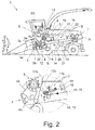
- FIG. 2 shows a proposed working machine 1 in a further embodiment, in which a particularly preferred design variant for the belt tensioner 17 is provided. All versions of the in Fig. 1 shown work machine 1 apply to in Fig. 2 shown work machine 1 accordingly.
- the belt tensioner 17 of Fig. 2 shown working machine 1 shows an above Auslenkkomponente, namely a rocker 17a, which has a different orientation than in Fig. 1 has shown rocker 17a.
- the elongated rocker 17a closes according to FIG Fig. 2 with a portion of extending from the tension roller 17 drive belt 14, here with the in Fig. 2 extending to the right extending section, a shallow angle. This makes it possible to achieve a particularly good clamping effect with good reproducibility of the measurement results.
- Fig. 1 made version for Fig. 2 corresponding.
Abstract
Die Erfindung betrifft eine landwirtschaftliche Arbeitsmaschine (1) mit einer Maschinensteuerung (2) zu ihrer Ansteuerung und/oder Überwachung, mit Arbeitsorganen (3) und einer Antriebsanordnung (7) für den Antrieb der Arbeitsorgane (3), wobei die Antriebsanordnung (7) über mindestens einen Riementrieb (10, 9) mit mindestens einem Arbeitsorgan (3) antriebstechnisch gekoppelt ist, wobei der Riementrieb (10, 9) eine Antriebsrolle (11), mindestens eine Abtriebsrolle (12) und einen Antriebsriemen (14) aufweist. Es wird vorgeschlagen, dass der Riementrieb (10, 9) einen sich je nach Riemendehnung auslenkenden Riemenspanner (17) mit einem Riemendehnungssensor (18, 21) aufweist, der zur Erzeugung eines Riemendehnungssignals (19, 22) die Auslenkung des Riemenspanners (17, 20) ermittelt und dass die Maschinensteuerung (2) die Arbeitsmaschine (1) während des Arbeitsbetriebs basierend auf dem Riemendehnungssignal (19, 22) und einem dem Riementrieb (10, 9) zugeordneten Kennwertsatz ansteuert und/oder überwacht.The invention relates to an agricultural working machine (1) with a machine control (2) for its control and / or monitoring, with working members (3) and a drive assembly (7) for driving the working members (3), wherein the drive assembly (7) via at least one belt drive (10, 9) with at least one working member (3) is drivingly coupled, wherein the belt drive (10, 9) has a drive roller (11), at least one output roller (12) and a drive belt (14). It is proposed that the belt drive (10, 9) has a belt tensioner (17) which deflects depending on the belt elongation and has a belt expansion sensor (18, 21) which generates the deflection of the belt tensioner (17, 20) in order to generate a belt extension signal (19, 22) ) and that the machine control unit (2) activates and / or monitors the work machine (1) during work operation based on the belt extension signal (19, 22) and a set of characteristic values assigned to the belt drive (10, 9).
Description
Die vorliegende Erfindung betrifft eine landwirtschaftliche Arbeitsmaschine gemäß dem Oberbegriff von Anspruch 1.The present invention relates to an agricultural work machine according to the preamble of
Bei der in Rede stehenden landwirtschaftlichen Arbeitsmaschine kann es sich um jedwede landwirtschaftliche Arbeitsmaschine handeln, die mit einer Maschinensteuerung und mindestens einem Riementrieb zur Übertragung von Antriebskraft ausgestattet ist. Dazu gehören beispielsweise Zugmaschinen, insbesondere Traktoren, selbstfahrende Erntemaschinen, insbesondere Feldhäcksler, Mähdrescher o. dgl.. Weiter sind von diesem Begriff nicht selbstfahrende Anbaugeräte sowie die Kombination der jeweiligen Zugmaschine mit dem Anbaugerät umfasst.The agricultural work machine in question may be any agricultural work machine equipped with a machine control and at least one belt drive for transmitting drive power. These include, for example, tractors, especially tractors, self-propelled harvesters, especially forage harvesters, combine harvester o. The like .. Furthermore, this term does not include self-propelled attachments and the combination of the respective tractor with the attachment.
Die landwirtschaftliche Arbeitsmaschine (
Es ist auch im Rahmen einer theoretischen Untersuchung bekannt geworden, ein über einen singulären Riementrieb übermitteltes Drehmoment über die Auslenkung eines Riemenspanners zu erfassen (
Der Erfindung liegt das Problem zugrunde, die bekannte landwirtschaftliche Arbeitsmaschine derart auszugestalten und weiterzubilden, dass deren Ansteuerung und/oder Überwachung insbesondere unter Berücksichtigung der übertragenen mechanischen Antriebsleistung mit einfachen Mitteln optimiert wird.The invention is based on the problem to design the known agricultural machine such and further, that their control and / or monitoring is optimized in particular taking into account the transmitted mechanical drive power with simple means.
Das obige Problem wird bei einer landwirtschaftlichen Arbeitsmaschine gemäß dem Oberbegriff von Anspruch 1 durch die Merkmale des kennzeichnenden Teils von Anspruch 1 gelöst.The above problem is solved in an agricultural machine according to the preamble of
Wesentlich ist die grundsätzliche Überlegung, dass sich auch komplexe Arbeitsmaschinen mit einer Mehrzahl von Riementrieben auf konstruktiv einfache und kostengünstige Weise ansteuern und/oder überwachen lassen, indem die Maschinensteuerung während des Arbeitsbetriebs mit einem Riemendehnungssignal des betreffenden Antriebsriemens versorgt wird. Dabei ist weiter erkannt worden, dass sich aus diesem dynamischen Riemendehnungssignal, das auf die lastabhängige Dehnung des jeweiligen Antriebsriemens zurückgeht, leicht auf die abgegebene und/oder aufgenommene Antriebsleistung geschlossen werden kann. Bei entsprechender Auslegung des Antriebsriemens kann bei konstanter Antriebsdrehzahl und bei Vernachlässigung von Verlusten wie Schlupf, Reibung o. dgl. von einer Proportionalität zwischen der dynamischen Riemendehnung und der abgegebenen bzw. aufgenommenen Antriebsleistung gesprochen werden, was die Auswertung besonders einfach gestaltet.Essential is the fundamental consideration that even complex machines with a plurality of belt drives can be controlled and / or monitored in a structurally simple and cost-effective manner by supplying the machine control during operation with a belt extension signal of the relevant drive belt. It has been further recognized that can be concluded from this dynamic belt extension signal, which is due to the load-dependent expansion of the respective drive belt, easily on the output and / or recorded drive power. With a suitable design of the drive belt can be spoken at a constant input speed and neglecting losses such as slippage, friction o. The like. Proportionality between the dynamic belt elongation and the output or recorded drive power, which makes the evaluation very simple.
Im Einzelnen weist der betreffende Riementrieb zunächst einen sich je nach Riemendehnung auslenkenden Riemenspanner mit einem Riemendehnungssensor auf. Zur Erzeugung eines Riemendehnungssignals ermittelt der Riemendehnungssensor die Auslenkung des Riemenspanners. Die Maschinensteuerung übernimmt dann die Ansteuerung und/oder Überwachung der Arbeitsmaschine während des Arbeitsbetriebs basierend auf dem mindestens einen Riemendehnungssignal und einem dem Riementrieb zugeordneten Kennwertsatz. Der Kennwertsatz trägt der Tatsache Rechnung, dass die mechanischen Eigenschaften des jeweiligen Antriebsriemens je nach dessen Auslegung unterschiedlich sind, was die Maschinensteuerung bei der Ansteuerung bzw. Überwachung der Arbeitsmaschine berücksichtigen muss.In detail, the relevant belt drive initially has a belt tensioner which deflects depending on the belt elongation and has a belt expansion sensor. To generate a belt extension signal, the belt expansion sensor determines the deflection of the belt tensioner. The machine control then takes over the control and / or monitoring of the working machine during the working operation based on the at least one belt extension signal and a characteristic set associated with the belt drive. The characteristic value set takes into account the fact that the mechanical properties of the respective drive belt are different depending on its design, which must be taken into account by the machine control in the control or monitoring of the working machine.
Es darf darauf hingewiesen werden, dass vorliegend das dynamische Riemendehnungssignal im Vordergrund steht, das sich während des Arbeitsbetriebs der Arbeitsmaschine ergibt. Das dynamische Riemendehnungssignal ergibt sich aus der über den Antriebsriemen übertragenen Antriebskraft, die über das E-Modul des Antriebsriemens zu einer entsprechenden Dehnung führt.It should be noted that in the present case, the dynamic belt elongation signal is in the foreground, which results during the working operation of the working machine. The dynamic belt extension signal results from the transmitted via the drive belt driving force, which leads via the modulus of elasticity of the drive belt to a corresponding strain.
Bei allen Ausführungen zu der vorschlagsgemäßen Lösung darf ferner darauf hingewiesen werden, dass mechanische Verluste wie Reibung und Schlupf vorliegend unberücksichtigt bleiben. Die Maschinensteuerung kann solche Verluste ggf. über entsprechende Korrekturfaktoren berücksichtigen.In all the remarks on the proposed solution, it should also be pointed out that mechanical losses such as friction and slip are not taken into account here. The machine control may possibly take such losses into account via corresponding correction factors.
Weiter ist zu berücksichtigen, dass der Riemenspanner passiv ausgestaltet sein kann und dann in der Regel über eine Federanordnung auf den Antriebsriemen federvorgespannt ist. Alternativ kann der Riemenspanner aber auch aktiv ausgestaltet sein und, ggf. zusätzlich zu einer Federanordnung, mit einem Antrieb auf den Antriebsriemen einwirken. In einem solchen Fall ist wiederum zu berücksichtigen, dass eine gewisse Riemendehnung auch auf den Antrieb des Riemenspanners zurückgehen kann, was beispielsweise über weitere Korrekturfaktoren berücksichtigt werden kann.It should also be noted that the belt tensioner can be made passive and then is usually spring biased by a spring arrangement on the drive belt. Alternatively, however, the belt tensioner can also be designed actively and, if appropriate in addition to a spring arrangement, act with a drive on the drive belt. In such a case, it must again be taken into consideration that a certain belt elongation can also be due to the drive of the belt tensioner, which can be taken into account, for example, via further correction factors.
Die antriebstechnische Kopplung zwischen der Antriebsanordnung und einem Arbeitsorgan kann über einen Riementrieb oder über mehrere antriebstechnisch hintereinander geschaltete Riementriebe vorgesehen sein. Ferner können sich von der Antriebsanordnung mehrere Riementriebe in parallelen Antriebssträngen abzweigen. Hier zeigt sich die Skalierbarkeit der vorschlagsgemäßen Lösung, indem ein und dasselbe Messprinzip, nämlich die Ermittlung der dynamischen Riemendehnung, nahezu unverändert an unterschiedlichen Riementrieben umsetzbar ist, ohne dass die Messanordnung verändert werden muss. Dies ist Gegenstand der bevorzugten Ausgestaltung von Anspruch 2.The drive technology coupling between the drive assembly and a working member may be provided via a belt drive or via a plurality of drive technology successively connected belt drives. Furthermore, a plurality of belt drives can branch off from the drive arrangement in parallel drive trains. This shows the scalability of the proposed solution by one and the same measuring principle, namely the determination of the dynamic belt elongation, almost unchanged on different belt drives can be implemented without the measurement arrangement must be changed. This is the subject of the preferred embodiment of
In einer besonders bevorzugten Variante von Anspruch 4 ist der Riemendehnungssensor als Winkelsensor ausgestaltet, der einer Schwinge des Riemenspanners zugeordnet ist. An einer solchen Schwinge des Riemenspanners befindet sich vorzugsweise eine Spannrolle, die auf dem Antriebsriemen abrollt. Ein solcher Winkelsensor lässt sich auf besonders einfache Weise an dem jeweiligen Riemenspanner anbringen. Insbesondere ist hier eine einfache Nachrüstung bei bestehenden landwirtschaftlichen Arbeitsmaschinen möglich.In a particularly preferred variant of
Die Verwendung des Riemendehnungssignals durch die Maschinensteuerung kann auf ganz unterschiedliche Weisen erfolgen. Gemäß Anspruch 5 kann es vorteilhaft sein, aus dem Riemendehnungssignal und dem Kennwertsatz die übertragene Antriebskraft oder die übertragene Antriebsleistung zu erzeugen. Denkbar ist aber auch, dass aus dem Riemendehnungssignal und dem Kennwertsatz lediglich ein theoretischer Vergleichswert erzeugt wird, aus dem sich die Leistungsaufnahmen der unterschiedlichen Arbeitsorgane vergleichen lassen.The use of the belt extension signal by the machine control can be done in quite different ways. According to
Die weiter bevorzugten Ausgestaltungen gemäß den Ansprüchen 6 bis 8 betreffen die Kalibrierung der Riemendehnungssensoren, um den jeweiligen Kennwertsatz auf die tatsächlich an der Arbeitsmaschine vorherrschenden Gegebenheiten anzupassen. Dabei geht es in erster Linie um die Ermittlung oder Anpassung des Zusammenhangs zwischen der Auslenkung des Riemenspanners und der übertragenen Antriebskraft und/oder der übertragenen Antriebsleistung. Die Notwendigkeit einer solchen Kalibrierung ergibt sich einerseits dadurch, dass jeder Antriebsriemen ein gewisses Einlaufverhalten aufweist, in dem sich eine gewisse plastische Dehnung einstellt. Eine weitere plastische Dehnung tritt in einer späteren Lebenszyklusphase des Antriebsriemens auf, die in erster Linie auf einen Verschleiß des Antriebsriemens zurückgeht.The further preferred embodiments according to
Bei der besonders bevorzugten Ausgestaltung gemäß Anspruch 9 nutzt die Maschinensteuerung das Riemendehnungssignal zur Umsetzung einer vom Benutzer auswählbaren Betriebsstrategie. Bei der Betriebsstrategie kann es sich beispielsweise um die Vorgabe handeln, die Leistungsaufnahme eines bestimmten Arbeitsorgans möglichst gering zu halten.In the particularly preferred embodiment according to claim 9, the machine control uses the belt extension signal to implement a user selectable operating strategy. The operating strategy may be, for example, the requirement to minimize the power consumption of a particular work organ.
Besonders vorteilhaft ist die vorschlagsgemäße Lösung bei einer Arbeitsmaschine mit mehreren, also mindestens zwei, Riementrieben. Gemäß Anspruch 10 ist erkannt worden, dass basierend auf den entsprechend mehreren Riemendehnungssignalen die Verteilung der Antriebsleistung der Antriebsanordnung auf die riemengetriebenen Arbeitsorgane oder auf Gruppen solcher riemengetriebener Arbeitsorgane ohne weiteres ermittelbar ist. Auch hier lässt sich eine oben angesprochene Betriebsstrategie, die beispielsweise eine vorbestimmte Verteilung der Antriebsleistung betrifft, mit einfachen Mitteln umsetzen.Particularly advantageous is the proposed solution in a work machine with several, so at least two belt drives. According to
Die weiter bevorzugten Ausgestaltungen gemäß den Ansprüchen 11 bis 14 betreffen die Überwachung der Arbeitsmaschine basierend auf dem vorschlagsgemäßen Riemendehnungssignal. Eine Erhöhung der Maschinenstandzeit lässt sich bei der Ausgabe einer Verschleißinformation gemäß Anspruch 11 oder einer Wartungsmeldung gemäß Anspruch 13 auf unkomplizierte Weise erhöhen.The further preferred embodiments according to
Bei der weiter bevorzugten Ausgestaltung gemäß Anspruch 15 schließlich ist eine Notfunktion realisiert derart, dass die Maschinensteuerung die Antriebsanordnung bei einer Maximaldehnung abschaltet, der ein Reißen des Antriebsriemens regelmäßig vorausgeht. Alternativ oder zusätzlich kann das tatsächliche Reißen des Antriebsriemens, das sich in einer Maximalauslenkung des Riemenspanners äußert, zur Abschaltung der Antriebsanordnung führen. Mit beiden Realisierungsmöglichkeiten wird verhindert, dass die Arbeitsmaschine durch das Reißen eines Antriebsriemens Schaden nimmt.In the further preferred embodiment according to
Im Folgenden wird die Erfindung anhand einer lediglich ein Ausführungsbeispiel darstellenden Zeichnung erläutert. In der Zeichnung zeigt
- Fig. 1
- eine vorschlagsgemäße landwirtschaftliche Arbeitsmaschine mit einem vorschlagsgemäßen Riemendehnungssensor und
- Fig. 2
- eine vorschlagsgemäße landwirtschaftliche Arbeitsmaschine mit einem vorschlagsgemäßen Riemendehnungssensor in einer weiteren Ausführungsform.
- Fig. 1
- a proposed agricultural work machine with a proposed belt strain sensor and
- Fig. 2
- a proposed agricultural work machine with a proposed belt strain sensor in another embodiment.
Wie im einleitenden Teil der Beschreibung erläutert, ist der Begriff "landwirtschaftliche Arbeitsmaschine" umfassend zu verstehen. Im dargestellten Ausführungsbeispiel handelt es sich bei der vorschlagsgemäßen, landwirtschaftlichen Arbeitsmaschine 1 um einen Feldhäcksler. Alle Ausführungen zu dem Feldhäcksler gelten für alle anderen Arten von landwirtschaftlichen Arbeitsmaschinen, insbesondere für einen Mähdrescher, entsprechend.As explained in the introductory part of the description, the term "agricultural work machine" is to be understood comprehensively. In the illustrated embodiment, it is in the proposed
Die landwirtschaftliche Arbeitsmaschine 1 ist mit einer Maschinensteuerung 2 ausgestattet, die die Ansteuerung und/oder Überwachung der Arbeitsmaschine 1 übernimmt. Die Arbeitsmaschine 1 ist ferner mit Arbeitsorganen 3-6 ausgestattet, die von einer Antriebsanordnung 7 angetrieben werden. Als Arbeitsorgan weist die Arbeitsmaschine 1 hier zunächst eine Vorpresseinheit 3 auf, die als Zuführeinrichtung für das Erntegut fungiert. Die Vorpresseinheit 3 ist mit zwei Paaren von einen Presskanal 3a ausbildenden Vorpresswalzen 3b-e ausgestattet. Dabei übernehmen die vorderen Vorpresswalzen 3b, 3c eine Vorverdichtung des aufgenommenen Ernteguts, während die hinteren Vorpresswalzen 3d, 3e eine gleichmäßige Verdichtung und einen Weitertransport des Ernteguts übernehmen.The
Für das Häckseln des aufgenommenen Ernteguts weist die Arbeitsmaschine 1 als weiteres Arbeitsorgan ein Häckselwerk 4 auf, an das sich als wiederum weiteres Arbeitsorgan eine Fördervorrichtung 5 für den Transport des gehäckselten Ernteguts in einen Auswurfkanal 8 anschließt. Das Häckselwerk 9 weist eine Messertrommel 9a auf.For chopping the picked crop, the working
Die vorschlagsgemäße Arbeitsmaschine 1 ist ferner mit einem Fahrantrieb 6 als weiteres Arbeitsorgan ausgestattet, bei dem es sich hier und vorzugsweise um einen hydraulischen Antrieb handelt.The proposed working
Die Antriebsanordnung 7 ist über mindestens einen Riementrieb 9, 10 mit mindestens einem Arbeitsorgan 3-6 antriebstechnisch gekoppelt. In der Zeichnung sind für eine gute Übersichtlichkeit lediglich zwei Riementriebe 9, 10 dargestellt. Der Riementrieb 9 dient der antriebstechnischen Kopplung der Antriebsanordnung 7 mit der Messertrommel 4a und der Fördervorrichtung 5. Der weitere Riementrieb 10, der in
Im Folgenden ist, wiederum im Sinne einer guten Übersichtlichkeit, fast durchweg von einem einzigen Riementrieb 9 die Rede. Alle Ausführungen gelten für alle weiteren, eventuell vorgesehenen Riementriebe entsprechend. Der Riementrieb 9 weist eine Antriebsrolle 11, hier und vorzugsweise mehrere Abtriebsrollen 12, 13 und einen Antriebsriemen 14 auf. Dabei stellt der in
Der Detaildarstellung gemäß
Vorschlagsgemäß ist es nun so, dass die Maschinensteuerung 2 die Arbeitsmaschine 1 während des Arbeitsbetriebs basierend auf dem Riemendehnungssignal 19 und einem dem Riementrieb 9 zugeordneten Kennwertsatz ansteuert und/oder überwacht. Auch hier darf darauf hingewiesen werden, dass alle Ausführungen zu dem Riemendehnungssignal 19 auf das Riemendehnungssignal 22 anwendbar sind.According to the proposal, it is now so that the
Bereits aus der Darstellung gemäß
Entsprechend ist es vorzugsweise so, dass die Antriebsanordnung 7 über mindestens zwei Riementriebe 9, 10 mit Arbeitsorganen 3-6 entsprechend antriebstechnisch gekoppelt ist, indem für jeden Riementrieb ein entsprechendes Riemendehnungssignal 19 erzeugt werden kann.Accordingly, it is preferably such that the
Für die Auswertung des Riemendehnungssignals 19 steht der Maschinensteuerung 2 der oben angesprochene Kennwertsatz zur Verfügung, der vorzugsweise eine Information zum Dehnungsverhalten des betreffenden Antriebsriemens 14, hier und vorzugsweise ein E-Modul (Elastizitätsmodul) des betreffenden Antriebsriemens 14, umfasst. Alternativ oder zusätzlich kann es vorgesehen sein, dass der Kennwertsatz einen Zusammenhang zwischen der Auslenkung des Riemenspanners 17 und der über den Antriebsriemen 14 übertragenen Antriebskraft umfasst. In diesem Zusammenhang darf darauf hingewiesen werden, dass mit der Antriebskraft stets ein entsprechendes Antriebs-Drehmoment an der entsprechenden Rolle des Riementriebs 9 einhergeht, das aber abhängig von der Geometrie der betreffenden Rolle ist, so dass zur Vereinfachung vorliegend stets von der über den Antriebsriemen 14 übertragenen Antriebskraft die Rede ist.For the evaluation of the
Der Begriff "Kennwertsatz" ist vorliegend weit zu verstehen. Er kann grundsätzlich auch nur einen einzigen Proportionalitätsfaktor, beispielsweise einen Proportionalitätsfaktor für den Zusammenhang zwischen der Auslenkung des Riemenspanners 17 und der über den Antriebsriemen 14 übertragenen Antriebskraft, umfassen. Denkbar ist auch, dass der Kennwertsatz eine Vielzahl von Parametern umfasst, wie weiter unten erläutert wird.The term "parameter set" is to be understood in the present case. In principle, it can also comprise only a single proportionality factor, for example a proportionality factor for the relationship between the deflection of the
Für die Realisierung des Riemenspanners 17 sind zahlreiche vorteilhafte Varianten denkbar. Vorzugsweise weist der Riemenspanner 17 eine Auslenkkomponente, hier eine Schwinge 17a, auf, an der eine Spannrolle 17b angeordnet ist. Die Spannrolle 17b wird über eine Federanordnung 17c auf den Antriebsriemen 14 gedrückt, so dass die Spannrolle 17b auf dem Antriebsriemen 14 abrollt.For the realization of the
Eine obige Ausgestaltung des Riemenspanners 17 mit der Auslenkkomponente 17a ermöglicht eine einfache und robuste sensorische Erfassung der Auslenkung des Riemenspanners 17. Hier und vorzugsweise ist der Riemendehnungssensor 18 als Wegsensor, hier und vorzugsweise als Winkelsensor, ausgestaltet, der der Auslenkkomponente, hier der Schwinge 17a, des Riemenspanners 17 zugeordnet ist. Im einfachsten Fall ist der Riemendehnungssensor 18 als Potentiometer ausgestaltet, das mit der Auslenkkomponente, hier der Schwinge 17a, deren Auslenkung ermittelnd, gekoppelt ist.An above embodiment of the
In diesem Zusammenhang darf darauf hingewiesen werden, dass der Riemenspanner 17 auch anders als oben erläutert aufgebaut sein kann. Denkbar ist beispielsweise, dass der Riemenspanner 17 zwei oder mehr als zwei Spannrollen 17b aufweist, die an einer entsprechenden Verstellkinematik angelenkt sind.In this context, it should be noted that the
In Abhängigkeit von der Steuer- bzw. Überwachungsstrategie der Maschinensteuerung 2 kann es vorteilhaft sein, dass die Maschinensteuerung 2 aus dem Riemendehnungssignal 19 und dem Kennwertsatz die übertragene Antriebskraft ermittelt. Alternativ oder zusätzlich kann es vorteilhaft sein, dass die Maschinensteuerung 2 aus dem Riemendehnungssignal 19 und der Riemengeschwindigkeit, insbesondere der Drehzahl und der Geometrie der Antriebsscheibe des Riementriebs, die jeweils übertragene Antriebsleistung ermittelt. Dies trägt dem Umstand Rechnung, dass die übertragene Antriebskraft und, bei konstanter Drehzahl der Antriebsscheibe, auch die übertragene Antriebsleistung, in einem linearen Zusammenhang zu der Dehnung des Antriebsriemens 14 steht, sofern man unterstellt, dass die Dehnung des Antriebsriemens 14 zumindest über den betreffenden Betriebsbereich mit einem konstanten E-Modul beschrieben werden kann.Depending on the control or monitoring strategy of the
Bei der obigen, vereinfachten Darstellung werden die an dem Riementrieb 9 auftretenden Verluste, insbesondere Schlupf- und Reibungsverluste, zunächst vernachlässigt.In the above simplified representation, the losses occurring on the belt drive 9, in particular slippage and friction losses, are initially neglected.
Wie im allgemeinen Teil der Beschreibung erläutert worden ist, verändert sich während des Lebenszyklus des Riementriebs 9 der Zusammenhang zwischen der Auslenkung des Riemenspanners 17 und der übertragenen Antriebskraft bzw. der übertragenen Antriebsleistung, da sich zumindest während einer Einlaufphase eine "erlaubte" plastische Dehnung des Antriebsriemens 14 ergibt. Entsprechend nimmt die Maschinensteuerung 2, vorzugsweise regelmäßig, einen Kalibriervorgang des Kennwertsatzes, insbesondere des Zusammenhangs zwischen der Auslenkung des Riemenspanners 17 und der übertragenen Antriebskraft bzw. der übertragenen Antriebsleistung, vor. Dabei kann im Rahmen des Kalibriervorgangs die Ermittlung des Kennwertsatzes oder die Anpassung eines bestehenden Kennwertsatzes vorgesehen sein.As has been explained in the general part of the description, during the life cycle of the belt drive 9, the relationship between the deflection of the
Eine besonders einfache Kalibrierung ergibt sich dadurch, dass die Maschinensteuerung 2 die Arbeitsmaschine 1 im Rahmen des Kalibriervorgangs in einem vordefinierten Kalibrier-Lastzustand des Riementriebs 9 betreibt und den Kennwertsatz aus dem im Kalibrier-Lastzustand ermittelten Riemendehnungssignal 19 ermittelt oder an das im Kalibrier-Lastzustand ermittelte Riemendehnungssignal 19 anpasst. Der Kalibrier-Lastzustand ist vorzugsweise dadurch definiert, dass mindestens ein im Leerlauf befindliches Arbeitsorgan 3-6 bei vorbestimmter Drehzahl bzw. Antriebsleistung der Antriebsanordnung 7 angetrieben wird. Beispielsweise ist es denkbar, dass vor dem Einfahren in den Feldbestand die Antriebsanordnung 7 mit maximaler Drehzahl betrieben wird, während sich die betreffenden Arbeitsorgane 3-6 noch im Leerlauf, also frei von Erntegut, befinden. Ein solcher Kalibriervorgang kann vorteilhafterweise nach einem Wendevorgang im Vorgewendebereich eines Feldes erfolgen, bevor die Arbeitsmaschine 1 in den Feldbestand einfährt.A particularly simple calibration results from the fact that the
Die Maschinensteuerung 2 dient vorzugsweise der Einstellung von Maschinenparametern der Antriebsanordnung 7 sowie von Maschinenparametern der Arbeitsorgane 3-6, um eine vom Benutzer ausgewählte Betriebsstrategie umzusetzen. Wie weiter oben angedeutet, kann beispielsweise die Betriebsstrategie speziell die Aufnahme von Antriebsleistung durch die Arbeitsorgane 3-6 und insbesondere die Verteilung der Antriebsleistung auf die Arbeitsorgane 3-6 umfassen. Hierfür ist in der Maschinensteuerung 2 vorzugsweise mindestens eine auswählbare Betriebsstrategie gespeichert, wobei die Maschinensteuerung 2 die Arbeitsmaschine 1, hier und vorzugsweise die Antriebsanordnung 7 und/oder mindestens ein Arbeitsorgan 3-6, basierend auf der Betriebsstrategie und dem mindestens einen Riemendehnungssignal 19 ansteuert.The
Beispielsweise kann es wie oben angedeutet vorgesehen sein, dass die Betriebsstrategie die von der Antriebsanordnung 7 erzeugte Antriebsleistung, hier und vorzugsweise deren Verteilung auf die Arbeitsorgane 3-6, betrifft, wobei die Maschinensteuerung 2 die von dem jeweiligen Arbeitsorgan 3-6 aufgenommene Antriebsleistung basierend auf dem jeweiligen Riemendehnungssignal 19 ermittelt.For example, it may be provided as indicated above that the operating strategy relates to the drive power generated by the
Alternativ oder zusätzlich kann es vorgesehen sein, dass die Betriebsstrategie die Einstellung der Maschinenparameter der Antriebsanordnung 7 in Abhängigkeit von deren abgegebener Antriebsleistung betrifft und dass die Maschinensteuerung 2 die abgegebene Antriebsleistung basierend auf dem Riemendehnungssignal 19 ermittelt.Alternatively or additionally, it can be provided that the operating strategy relates to the adjustment of the machine parameters of the
Wiederum alternativ oder zusätzlich kann es vorgesehen sein, dass die Betriebsstrategie die Einstellung der Maschinenparameter mindestens eines Arbeitsorgans 3-6 in Abhängigkeit von dessen aufgenommener Antriebsleistung betrifft, wobei die Maschinensteuerung 2 die aufgenommene Antriebsleistung basierend auf dem jeweiligen Riemendehnungssignal 19 ermittelt.Again alternatively or additionally, it can be provided that the operating strategy relates to the setting of the machine parameters of at least one working element 3-6 as a function of its recorded drive power, wherein the
Es darf auch hinsichtlich der Erläuterung der obigen Betriebsstrategien darauf hingewiesen werden, dass diese Darstellung vereinfacht ist und das Auftreten mechanischer Verluste nicht berücksichtigt ist.It may also be pointed out, with regard to the explanation of the above operating strategies, that this representation is simplified and the occurrence of mechanical losses is not taken into account.
Wie oben angesprochen, lässt sich die vorschlagsgemäße Lösung besonders vorteilhaft bei einer Arbeitsmaschine 1 mit mehreren Riementrieben 9, 10 anwenden. Dann ist es so, dass die Maschinensteuerung 2 aus den Riemendehnungssignalen 19, 22 und den dazugehörigen Kennwertsätzen die Verteilung der Antriebsleistung der Antriebsanordnung 7 auf riemengetriebene Arbeitsorgane 3-6 oder auf Gruppen von riemengetriebenen Arbeitsorganen 3-6 ermittelt. Dabei kann die Ermittlung der weiter oben angesprochenen, theoretischen Vergleichswerte ausreichend sein, da beispielsweise eine prozentuale Verteilung der Antriebsleistung auf die jeweiligen Arbeitsorgane 3-6 bereits eine hinreichende Grundlage für die Ansteuerung und/oder Überwachung der Arbeitsmaschine 1 sein kann.As mentioned above, the proposed solution can be particularly advantageous in a
Hinsichtlich der Überwachung der Arbeitsmaschine 1 kann es vorteilhaft sein, dass der Kennwertsatz eine Information über den Einfluss des Riemenverschleißes auf das Dehnungsverhalten des Antriebsriemens 14 umfasst, wobei die Maschinensteuerung 2 basierend auf dem Riemendehnungssignal 19 und dem Kennwertsatz eine Verschleißinformation zum Verschleiß des Antriebsriemens 14 des betreffenden Riementriebs 9 erzeugt. In besonders bevorzugter Ausgestaltung wird diese Verschleißinformation über die in
Grundsätzlich ist für einen Antriebsriemen 14 ein nomineller Lebenszyklus mit mindestens zwei Lebenszyklusphasen vorgesehen, zu denen jedenfalls eine Einlaufphase und eine sich daran anschließende Betriebsphase gehört. Vorzugsweise umfasst der Kennwertsatz eine Information über das Dehnungsverhalten des Antriebsriemens 14 in den verschiedenen Lebenszyklusphasen, wobei die Maschinensteuerung 2 die Ansteuerung bzw. Überwachung der Arbeitsmaschine 1 in Abhängigkeit von der jeweils aktuellen Lebenszyklusphase und von dem jeweiligen Kennwertsatz vornimmt. Entsprechend stellt sich die Maschinensteuerung 2 durch eine entsprechende Anpassung des Kennwertsatzes darauf ein, dass die Einlaufphase, die regelmäßig etwa 100 Betriebsstunden andauert, ein Nachspannen des Antriebsriemens 14 und einen entsprechenden Kalibriervorgang erfordert. Dies kann die Maschinensteuerung 2 dem Bediener über die Mensch-Maschine-Schnittstelle 23 rechtzeitig zur Kenntnis bringen, so dass die Maschinenstandzeit wie oben angedeutet, erhöht werden kann.In principle, a nominal life cycle with at least two life cycle phases is provided for a
Eine einfache Variante für die Überwachung der Arbeitsmaschine 1 besteht darin, dass der Kennwertsatz einen Grenzdehnbereich für den Antriebsriemen 14 umfasst, wobei die Maschinensteuerung 2 bei Erreichen des Grenzdehnbereichs eine auf den betreffenden Riementrieb 9 gerichtete Grenzdehnroutine ablaufen lässt. Bei der Grenzdehnroutine handelt es sich vorzugsweise um ein Softwareprogramm, das in einer Rechenvorrichtung der Maschinensteuerung 2 abläuft. Der Grenzdehnbereich kann grundsätzlich fest vorgegeben sein. Denkbar ist aber auch, dass der Grenzdehnbereich in Abhängigkeit von der Lebenszyklusphase des Antriebsriemens 14 veränderlich ist.A simple variant for the monitoring of the working
Für die Umsetzung der obigen Grenzdehnroutine sind verschiedene vorteilhafte Varianten denkbar. Hier und vorzugsweise ist es so, dass die Maschinensteuerung 2 in der Grenzdehnroutine eine Wartungsmeldung, hier und vorzugsweise einen Hinweis auf die Notwendigkeit eines Nachspannens, über die Mensch-Maschine-Schnittstelle 23 ausgibt. Alternativ oder zusätzlich kann es vorgesehen sein, dass die Maschinensteuerung 2 in der Grenzdehnroutine die Antriebsanordnung 7 und/oder das mindestens eine Arbeitsorgan 3-6 mit begrenzter, insbesondere reduzierter, übertragener Antriebsleistung für den betreffenden Riementrieb 9 ansteuert.For the implementation of the above Grenzdehnroutine various advantageous variants are conceivable. Here and preferably, it is such that the
Eine für den Bediener besonders komfortable Variante ergibt sich dadurch, dass die Maschinensteuerung 2 basierend auf dem Riemendehnungssignal 19 und dem Kennwertsatz eine Prognose über den Verschleiß des Antriebsriemens 17 erzeugt, die vorzugsweise über die Mensch-Maschine-Schnittstelle 23 ausgegeben wird. Eine solche Prognose lässt sich basierend auf den oben angesprochenen Informationen zu dem Lebenszyklus des Antriebsriemens 14 erzeugen. Dadurch ist es dem Bediener möglich, das Nachspannen des Antriebsriemens 14 sowie einen eventuell erforderlichen Wechsel des Antriebsriemens 14 frühzeitig zu planen, so dass sich die Maschinenstandzeit weiter erhöht.A particularly convenient for the operator variant results from the fact that the
Um zu vermeiden, dass ein unvorhergesehenes Reißen des Antriebsriemens 14 zu Schäden innerhalb der Arbeitsmaschine 1 führt, ist es vorzugsweise vorgesehen, dass der Kennwertsatz eine Maximaldehnung umfasst und dass die Maschinensteuerung 2 die Antriebsanordnung 7 bei Erreichen der Maximaldehnung abschaltet. Alternativ oder zusätzlich kann es vorgesehen sein, dass die Maschinensteuerung 2 die Antriebsanordnung 7 bei Erreichen einer Maximalauslenkung des Riemenspanners 17 abschaltet, so dass ein tatsächlich erfolgtes Reißen des Antriebsriemens 14 zu einem kurzfristigen Abschalten der Antriebsanordnung 7 führt. Der letztgenannte Fall betrifft insbesondere die Situation, in der der Antriebsriemen 14 von der Antriebsrolle 11 und/oder der Abtriebsrolle 12, 13 springt, was beispielsweise durch den Eintritt von Verunreinigungen in die Abrollbereiche der Antriebsrolle 11 bzw. der Abtriebsrollen 12, 13 stattfinden kann.In order to avoid that an unforeseen tearing of the
Schließlich darf noch darauf hingewiesen werden, dass aus dem Riemendehnungssignal 19 grundsätzlich auch eine plastische Dehnung des Antriebsriemens 14 erfasst werden kann. Sofern dies außerhalb der Einlaufphase erfolgt, ist je nach Auslegung des Antriebsriemens 14 damit zu rechnen, dass ein Reißen des Antriebsriemens 14 ansteht. Die Grenzen hierfür können wiederum von dem Kennwertsatz des betreffenden Antriebsriemens 14 umfasst sein und von der Maschinensteuerung 2 entsprechend ausgewertet werden.Finally, it should be pointed out that from the
Das dynamische Riemendehnungssignal 19 unterliegt aufgrund der Tatsache, dass es während des Arbeitsbetriebs aufgenommen wird, ständigen Schwankungen sowie einem gewissen Rauschen. Entsprechend ist es vorzugsweise so, dass das Riemendehnungssignal 19 einer Filterung, insbesondere einer dynamischen Mittelwertbildung, unterzogen wird, bevor es von der Maschinensteuerung 2, wie oben erläutert, ausgewertet wird.The dynamic
Die Darstellung gemäß
Der Riemenspanner 17 der in
- 11
- Arbeitsmaschineworking machine
- 22
- Maschinensteuerungmachine control
- 33
- Vorpresseinheitprepressing
- 3a3a
- PresskanalPress channel
- 3b3b
- 1. Vorpresswalze vorne1. Prepress roller front
- 3c3c
- 2. Vorpresswalze vorne2. Prepress roller front
- 3d3d
- 1. Vorpresswalze hinten1. Prepress roller at the back
- 3e3e
- 2. Vorpresswalze hinten2. Prepress roller behind
- 44
- HäckselwerkHäckselwerk
- 4a4a
- Messertrommelcutterhead
- 55
- Fördervorrichtungconveyor
- 66
- Fahrantriebtraction drive
- 77
- Antriebsanordnungdrive arrangement
- 88th
- Auswurfkanalchute
- 9, 109, 10
- Riementriebbelt drive
- 1111
- Antriebsrollecapstan
- 12, 1312, 13
- Abtriebsrolledriven roller
- 1414
- Antriebsriemendrive belts
- 1515
- Zugtrumdrive span
- 1616
- Lostrumslack run
- 1717
- 1. Riemenspanner1. Belt tensioner
- 17a17a
-
Schwinge 1. Riemenspanner
Swingarm 1. Belt tensioner - 17b17b
-
Spannrolle 1. Riemenspanner
Tension pulley 1. Belt tensioner - 17c17c
-
Federanordnung 1. Riemenspanner
Spring arrangement 1. Belt tensioner - 1818
-
Riemendehnungssensor 1. Riemenspanner
Belt expansion sensor 1. Belt tensioner - 1919
-
Riemendehnungssignal 1. Riemenspanner
Belt extension signal 1. Belt tensioner - 2020
- 2. Riemenspanner2. Belt tensioner
- 2121
-
Riemendehnungssensor 2. Riemenspanner
Belt expansion sensor 2. Belt tensioner - 2222
-
Riemendehnungssignal 2. Riemenspanner
Belt extension signal 2. Belt tensioner - 2323
- Mensch-Maschine-SchnittstelleHuman-machine interface
Claims (15)
dadurch gekennzeichnet,
dass der Riementrieb (9, 10) einen sich je nach Riemendehnung auslenkenden Riemenspanner (17, 20) mit einem Riemendehnungssensor (18, 21) aufweist, der zur Erzeugung eines Riemendehnungssignals (19, 22) die Auslenkung des Riemenspanners (17, 20) ermittelt und dass die Maschinensteuerung (2) die Arbeitsmaschine (1) während des Arbeitsbetriebs basierend auf dem Riemendehnungssignal (19, 22) und einem dem Riementrieb (9, 10) zugeordneten Kennwertsatz ansteuert und/oder überwacht.Agricultural work machine with a machine control (2) for its control and / or monitoring, with work organs (3-6) and a drive arrangement (7) for driving the working members (3-6), wherein the drive assembly (7) via at least one belt drive (9, 10) with at least one working member (3-6) is drivingly coupled, wherein the belt drive (9, 10) has a drive roller (11), at least one output roller (12, 13) and a drive belt (14),
characterized,
in that the belt drive (9, 10) has a belt tensioner (17, 20) which deflects depending on the belt elongation and has a belt extension sensor (18, 21) which determines the deflection of the belt tensioner (17, 20) in order to generate a belt extension signal (19, 22) and that the machine control unit (2) controls and / or monitors the work machine (1) during work operation based on the belt extension signal (19, 22) and a set of characteristic values associated with the belt drive (9, 10).
Applications Claiming Priority (2)
| Application Number | Priority Date | Filing Date | Title |
|---|---|---|---|
| DE102015116330 | 2015-09-28 | ||
| DE102015121209.9A DE102015121209A1 (en) | 2015-09-28 | 2015-12-07 | Agricultural working machine |
Publications (2)
| Publication Number | Publication Date |
|---|---|
| EP3146833A1 true EP3146833A1 (en) | 2017-03-29 |
| EP3146833B1 EP3146833B1 (en) | 2019-06-12 |
Family
ID=56289427
Family Applications (1)
| Application Number | Title | Priority Date | Filing Date |
|---|---|---|---|
| EP16176869.2A Active EP3146833B1 (en) | 2015-09-28 | 2016-06-29 | Agricultural work machine |
Country Status (1)
| Country | Link |
|---|---|
| EP (1) | EP3146833B1 (en) |
Cited By (1)
| Publication number | Priority date | Publication date | Assignee | Title |
|---|---|---|---|---|
| EP4275473A1 (en) * | 2022-05-09 | 2023-11-15 | Deere & Company | Crop quantity sensing system and method for a mower drive assembly |
Families Citing this family (2)
| Publication number | Priority date | Publication date | Assignee | Title |
|---|---|---|---|---|
| DE102020115974A1 (en) * | 2020-06-17 | 2021-12-23 | Claas Selbstfahrende Erntemaschinen Gmbh | Self-propelled harvesting machine and method for operating a self-propelled harvesting machine |
| DE102021103078A1 (en) | 2021-02-10 | 2022-08-11 | Arburg Gmbh + Co Kg | Device and method for monitoring and adjusting belt tension |
Citations (6)
| Publication number | Priority date | Publication date | Assignee | Title |
|---|---|---|---|---|
| GB911361A (en) | 1958-03-11 | 1962-11-28 | Massey Ferguson Ltd | Improvements in or relating to mobile agricultural crop collecting and treating machines |
| US4130980A (en) * | 1977-01-06 | 1978-12-26 | International Harvester Company | Combine automatic travel control system |
| DD158674A1 (en) | 1981-04-28 | 1983-01-26 | Dietmar Metzner | DEVICE FOR MEASURING TORQUE |
| DE19634619A1 (en) * | 1995-08-28 | 1997-03-06 | Nippon Denso Co | Accessory torque detection device for a belt transmission |
| EP1397954A1 (en) * | 2002-09-13 | 2004-03-17 | Usines Claas France | Agricultural machine |
| EP2223588A2 (en) * | 2009-02-27 | 2010-09-01 | Deere & Company | Automotive harvesting machine |
-
2016
- 2016-06-29 EP EP16176869.2A patent/EP3146833B1/en active Active
Patent Citations (6)
| Publication number | Priority date | Publication date | Assignee | Title |
|---|---|---|---|---|
| GB911361A (en) | 1958-03-11 | 1962-11-28 | Massey Ferguson Ltd | Improvements in or relating to mobile agricultural crop collecting and treating machines |
| US4130980A (en) * | 1977-01-06 | 1978-12-26 | International Harvester Company | Combine automatic travel control system |
| DD158674A1 (en) | 1981-04-28 | 1983-01-26 | Dietmar Metzner | DEVICE FOR MEASURING TORQUE |
| DE19634619A1 (en) * | 1995-08-28 | 1997-03-06 | Nippon Denso Co | Accessory torque detection device for a belt transmission |
| EP1397954A1 (en) * | 2002-09-13 | 2004-03-17 | Usines Claas France | Agricultural machine |
| EP2223588A2 (en) * | 2009-02-27 | 2010-09-01 | Deere & Company | Automotive harvesting machine |
Cited By (1)
| Publication number | Priority date | Publication date | Assignee | Title |
|---|---|---|---|---|
| EP4275473A1 (en) * | 2022-05-09 | 2023-11-15 | Deere & Company | Crop quantity sensing system and method for a mower drive assembly |
Also Published As
| Publication number | Publication date |
|---|---|
| EP3146833B1 (en) | 2019-06-12 |
Similar Documents
| Publication | Publication Date | Title |
|---|---|---|
| DE3048255C2 (en) | Drive device for an agricultural machine, in particular a combine harvester | |
| DE19903471C1 (en) | Crop machine throughput measurement arrangement derives throughput from distance between pre-baling rollers and crop speed, corrects for displacement force on pre-baling roller | |
| EP1790210B1 (en) | Feeding device for a forage harvester | |
| DE102018107804A1 (en) | Height control system for a header | |
| DE10312897A1 (en) | Device for wrapping a bale with a wrapping web, baling press and sensor | |
| EP3146833B1 (en) | Agricultural work machine | |
| DE102012212846A1 (en) | baler | |
| EP2936969A1 (en) | Combination of a towing vehicle and a harvesting machine pulled by it | |
| EP1847169A1 (en) | Method and device for regulating the cutting length of a straw cutter in an agricultural harvester | |
| EP2248411B1 (en) | Harvester | |
| EP3443833A1 (en) | Powertrain to drive a work unit of a self-propelled harvesting machine | |
| EP2218320B1 (en) | Chaff cutter with setting-coupled supply and goods processing device | |
| EP2952087A1 (en) | Drive system for a self-propelled harvesting machine | |
| EP2636297B1 (en) | Self-propelled harvester | |
| DE102016117867A1 (en) | baler | |
| BE1026188B1 (en) | Forage harvester with cutting length-dependent speed of the conditioning device | |
| DE102004056233A1 (en) | Agricultural working machine with a drive motor | |
| EP3266299B1 (en) | Baling press | |
| EP3106024A1 (en) | Round baler with means for guiding a compression belt | |
| DE102015121209A1 (en) | Agricultural working machine | |
| EP1525787B1 (en) | Method and device to control engine speed in an agricultural working machine | |
| EP3721700B1 (en) | Round baler and bale wrapping device for a round baler | |
| EP2108248B1 (en) | Chaff cutter and intake device for same | |
| DE10242426A1 (en) | Method for controlling a transfer device | |
| EP3300578B1 (en) | Method for controlling an agricultural machine |
Legal Events
| Date | Code | Title | Description |
|---|---|---|---|
| PUAI | Public reference made under article 153(3) epc to a published international application that has entered the european phase |
Free format text: ORIGINAL CODE: 0009012 |
|
| STAA | Information on the status of an ep patent application or granted ep patent |
Free format text: STATUS: THE APPLICATION HAS BEEN PUBLISHED |
|
| AK | Designated contracting states |
Kind code of ref document: A1 Designated state(s): AL AT BE BG CH CY CZ DE DK EE ES FI FR GB GR HR HU IE IS IT LI LT LU LV MC MK MT NL NO PL PT RO RS SE SI SK SM TR |
|
| AX | Request for extension of the european patent |
Extension state: BA ME |
|
| STAA | Information on the status of an ep patent application or granted ep patent |
Free format text: STATUS: REQUEST FOR EXAMINATION WAS MADE |
|
| 17P | Request for examination filed |
Effective date: 20170929 |
|
| RBV | Designated contracting states (corrected) |
Designated state(s): AL AT BE BG CH CY CZ DE DK EE ES FI FR GB GR HR HU IE IS IT LI LT LU LV MC MK MT NL NO PL PT RO RS SE SI SK SM TR |
|
| STAA | Information on the status of an ep patent application or granted ep patent |
Free format text: STATUS: EXAMINATION IS IN PROGRESS |
|
| 17Q | First examination report despatched |
Effective date: 20180503 |
|
| GRAP | Despatch of communication of intention to grant a patent |
Free format text: ORIGINAL CODE: EPIDOSNIGR1 |
|
| STAA | Information on the status of an ep patent application or granted ep patent |
Free format text: STATUS: GRANT OF PATENT IS INTENDED |
|
| INTG | Intention to grant announced |
Effective date: 20190226 |
|
| GRAS | Grant fee paid |
Free format text: ORIGINAL CODE: EPIDOSNIGR3 |
|
| GRAA | (expected) grant |
Free format text: ORIGINAL CODE: 0009210 |
|
| STAA | Information on the status of an ep patent application or granted ep patent |
Free format text: STATUS: THE PATENT HAS BEEN GRANTED |
|
| AK | Designated contracting states |
Kind code of ref document: B1 Designated state(s): AL AT BE BG CH CY CZ DE DK EE ES FI FR GB GR HR HU IE IS IT LI LT LU LV MC MK MT NL NO PL PT RO RS SE SI SK SM TR |
|
| REG | Reference to a national code |
Ref country code: GB Ref legal event code: FG4D Free format text: NOT ENGLISH |
|
| REG | Reference to a national code |
Ref country code: CH Ref legal event code: EP |
|
| REG | Reference to a national code |
Ref country code: AT Ref legal event code: REF Ref document number: 1141333 Country of ref document: AT Kind code of ref document: T Effective date: 20190615 |
|
| REG | Reference to a national code |
Ref country code: DE Ref legal event code: R096 Ref document number: 502016004985 Country of ref document: DE |
|
| REG | Reference to a national code |
Ref country code: IE Ref legal event code: FG4D Free format text: LANGUAGE OF EP DOCUMENT: GERMAN |
|
| REG | Reference to a national code |
Ref country code: NL Ref legal event code: MP Effective date: 20190612 |
|
| REG | Reference to a national code |
Ref country code: LT Ref legal event code: MG4D |
|
| PG25 | Lapsed in a contracting state [announced via postgrant information from national office to epo] |
Ref country code: SE Free format text: LAPSE BECAUSE OF FAILURE TO SUBMIT A TRANSLATION OF THE DESCRIPTION OR TO PAY THE FEE WITHIN THE PRESCRIBED TIME-LIMIT Effective date: 20190612 Ref country code: LT Free format text: LAPSE BECAUSE OF FAILURE TO SUBMIT A TRANSLATION OF THE DESCRIPTION OR TO PAY THE FEE WITHIN THE PRESCRIBED TIME-LIMIT Effective date: 20190612 Ref country code: HR Free format text: LAPSE BECAUSE OF FAILURE TO SUBMIT A TRANSLATION OF THE DESCRIPTION OR TO PAY THE FEE WITHIN THE PRESCRIBED TIME-LIMIT Effective date: 20190612 Ref country code: NO Free format text: LAPSE BECAUSE OF FAILURE TO SUBMIT A TRANSLATION OF THE DESCRIPTION OR TO PAY THE FEE WITHIN THE PRESCRIBED TIME-LIMIT Effective date: 20190912 Ref country code: AL Free format text: LAPSE BECAUSE OF FAILURE TO SUBMIT A TRANSLATION OF THE DESCRIPTION OR TO PAY THE FEE WITHIN THE PRESCRIBED TIME-LIMIT Effective date: 20190612 Ref country code: FI Free format text: LAPSE BECAUSE OF FAILURE TO SUBMIT A TRANSLATION OF THE DESCRIPTION OR TO PAY THE FEE WITHIN THE PRESCRIBED TIME-LIMIT Effective date: 20190612 |
|
| PG25 | Lapsed in a contracting state [announced via postgrant information from national office to epo] |
Ref country code: RS Free format text: LAPSE BECAUSE OF FAILURE TO SUBMIT A TRANSLATION OF THE DESCRIPTION OR TO PAY THE FEE WITHIN THE PRESCRIBED TIME-LIMIT Effective date: 20190612 Ref country code: BG Free format text: LAPSE BECAUSE OF FAILURE TO SUBMIT A TRANSLATION OF THE DESCRIPTION OR TO PAY THE FEE WITHIN THE PRESCRIBED TIME-LIMIT Effective date: 20190912 Ref country code: LV Free format text: LAPSE BECAUSE OF FAILURE TO SUBMIT A TRANSLATION OF THE DESCRIPTION OR TO PAY THE FEE WITHIN THE PRESCRIBED TIME-LIMIT Effective date: 20190612 Ref country code: GR Free format text: LAPSE BECAUSE OF FAILURE TO SUBMIT A TRANSLATION OF THE DESCRIPTION OR TO PAY THE FEE WITHIN THE PRESCRIBED TIME-LIMIT Effective date: 20190913 |
|
| PG25 | Lapsed in a contracting state [announced via postgrant information from national office to epo] |
Ref country code: NL Free format text: LAPSE BECAUSE OF FAILURE TO SUBMIT A TRANSLATION OF THE DESCRIPTION OR TO PAY THE FEE WITHIN THE PRESCRIBED TIME-LIMIT Effective date: 20190612 Ref country code: PT Free format text: LAPSE BECAUSE OF FAILURE TO SUBMIT A TRANSLATION OF THE DESCRIPTION OR TO PAY THE FEE WITHIN THE PRESCRIBED TIME-LIMIT Effective date: 20191014 Ref country code: RO Free format text: LAPSE BECAUSE OF FAILURE TO SUBMIT A TRANSLATION OF THE DESCRIPTION OR TO PAY THE FEE WITHIN THE PRESCRIBED TIME-LIMIT Effective date: 20190612 Ref country code: SK Free format text: LAPSE BECAUSE OF FAILURE TO SUBMIT A TRANSLATION OF THE DESCRIPTION OR TO PAY THE FEE WITHIN THE PRESCRIBED TIME-LIMIT Effective date: 20190612 Ref country code: CZ Free format text: LAPSE BECAUSE OF FAILURE TO SUBMIT A TRANSLATION OF THE DESCRIPTION OR TO PAY THE FEE WITHIN THE PRESCRIBED TIME-LIMIT Effective date: 20190612 Ref country code: EE Free format text: LAPSE BECAUSE OF FAILURE TO SUBMIT A TRANSLATION OF THE DESCRIPTION OR TO PAY THE FEE WITHIN THE PRESCRIBED TIME-LIMIT Effective date: 20190612 |
|
| REG | Reference to a national code |
Ref country code: CH Ref legal event code: PL |
|
| PG25 | Lapsed in a contracting state [announced via postgrant information from national office to epo] |
Ref country code: IS Free format text: LAPSE BECAUSE OF FAILURE TO SUBMIT A TRANSLATION OF THE DESCRIPTION OR TO PAY THE FEE WITHIN THE PRESCRIBED TIME-LIMIT Effective date: 20191012 Ref country code: ES Free format text: LAPSE BECAUSE OF FAILURE TO SUBMIT A TRANSLATION OF THE DESCRIPTION OR TO PAY THE FEE WITHIN THE PRESCRIBED TIME-LIMIT Effective date: 20190612 Ref country code: IT Free format text: LAPSE BECAUSE OF FAILURE TO SUBMIT A TRANSLATION OF THE DESCRIPTION OR TO PAY THE FEE WITHIN THE PRESCRIBED TIME-LIMIT Effective date: 20190612 Ref country code: SM Free format text: LAPSE BECAUSE OF FAILURE TO SUBMIT A TRANSLATION OF THE DESCRIPTION OR TO PAY THE FEE WITHIN THE PRESCRIBED TIME-LIMIT Effective date: 20190612 |
|
| REG | Reference to a national code |
Ref country code: DE Ref legal event code: R097 Ref document number: 502016004985 Country of ref document: DE |
|
| PG25 | Lapsed in a contracting state [announced via postgrant information from national office to epo] |
Ref country code: TR Free format text: LAPSE BECAUSE OF FAILURE TO SUBMIT A TRANSLATION OF THE DESCRIPTION OR TO PAY THE FEE WITHIN THE PRESCRIBED TIME-LIMIT Effective date: 20190612 Ref country code: MC Free format text: LAPSE BECAUSE OF FAILURE TO SUBMIT A TRANSLATION OF THE DESCRIPTION OR TO PAY THE FEE WITHIN THE PRESCRIBED TIME-LIMIT Effective date: 20190612 |
|
| PLBE | No opposition filed within time limit |
Free format text: ORIGINAL CODE: 0009261 |
|
| STAA | Information on the status of an ep patent application or granted ep patent |
Free format text: STATUS: NO OPPOSITION FILED WITHIN TIME LIMIT |
|
| PG25 | Lapsed in a contracting state [announced via postgrant information from national office to epo] |
Ref country code: PL Free format text: LAPSE BECAUSE OF FAILURE TO SUBMIT A TRANSLATION OF THE DESCRIPTION OR TO PAY THE FEE WITHIN THE PRESCRIBED TIME-LIMIT Effective date: 20190612 Ref country code: IE Free format text: LAPSE BECAUSE OF NON-PAYMENT OF DUE FEES Effective date: 20190629 Ref country code: DK Free format text: LAPSE BECAUSE OF FAILURE TO SUBMIT A TRANSLATION OF THE DESCRIPTION OR TO PAY THE FEE WITHIN THE PRESCRIBED TIME-LIMIT Effective date: 20190612 |
|
| 26N | No opposition filed |
Effective date: 20200313 |
|
| PG25 | Lapsed in a contracting state [announced via postgrant information from national office to epo] |
Ref country code: LU Free format text: LAPSE BECAUSE OF NON-PAYMENT OF DUE FEES Effective date: 20190629 Ref country code: CH Free format text: LAPSE BECAUSE OF NON-PAYMENT OF DUE FEES Effective date: 20190630 Ref country code: LI Free format text: LAPSE BECAUSE OF NON-PAYMENT OF DUE FEES Effective date: 20190630 Ref country code: IS Free format text: LAPSE BECAUSE OF FAILURE TO SUBMIT A TRANSLATION OF THE DESCRIPTION OR TO PAY THE FEE WITHIN THE PRESCRIBED TIME-LIMIT Effective date: 20200224 Ref country code: SI Free format text: LAPSE BECAUSE OF FAILURE TO SUBMIT A TRANSLATION OF THE DESCRIPTION OR TO PAY THE FEE WITHIN THE PRESCRIBED TIME-LIMIT Effective date: 20190612 |
|
| PG2D | Information on lapse in contracting state deleted |
Ref country code: IS |
|
| PG25 | Lapsed in a contracting state [announced via postgrant information from national office to epo] |
Ref country code: FR Free format text: LAPSE BECAUSE OF NON-PAYMENT OF DUE FEES Effective date: 20190812 |
|
| GBPC | Gb: european patent ceased through non-payment of renewal fee |
Effective date: 20200629 |
|
| PG25 | Lapsed in a contracting state [announced via postgrant information from national office to epo] |
Ref country code: GB Free format text: LAPSE BECAUSE OF NON-PAYMENT OF DUE FEES Effective date: 20200629 |
|
| PG25 | Lapsed in a contracting state [announced via postgrant information from national office to epo] |
Ref country code: CY Free format text: LAPSE BECAUSE OF FAILURE TO SUBMIT A TRANSLATION OF THE DESCRIPTION OR TO PAY THE FEE WITHIN THE PRESCRIBED TIME-LIMIT Effective date: 20190612 |
|
| PG25 | Lapsed in a contracting state [announced via postgrant information from national office to epo] |
Ref country code: HU Free format text: LAPSE BECAUSE OF FAILURE TO SUBMIT A TRANSLATION OF THE DESCRIPTION OR TO PAY THE FEE WITHIN THE PRESCRIBED TIME-LIMIT; INVALID AB INITIO Effective date: 20160629 Ref country code: MT Free format text: LAPSE BECAUSE OF FAILURE TO SUBMIT A TRANSLATION OF THE DESCRIPTION OR TO PAY THE FEE WITHIN THE PRESCRIBED TIME-LIMIT Effective date: 20190612 |
|
| PG25 | Lapsed in a contracting state [announced via postgrant information from national office to epo] |
Ref country code: MK Free format text: LAPSE BECAUSE OF FAILURE TO SUBMIT A TRANSLATION OF THE DESCRIPTION OR TO PAY THE FEE WITHIN THE PRESCRIBED TIME-LIMIT Effective date: 20190612 |
|
| REG | Reference to a national code |
Ref country code: AT Ref legal event code: MM01 Ref document number: 1141333 Country of ref document: AT Kind code of ref document: T Effective date: 20210629 |
|
| PG25 | Lapsed in a contracting state [announced via postgrant information from national office to epo] |
Ref country code: AT Free format text: LAPSE BECAUSE OF NON-PAYMENT OF DUE FEES Effective date: 20210629 |
|
| P01 | Opt-out of the competence of the unified patent court (upc) registered |
Effective date: 20230516 |
|
| PGFP | Annual fee paid to national office [announced via postgrant information from national office to epo] |
Ref country code: DE Payment date: 20230620 Year of fee payment: 8 |
|
| PGFP | Annual fee paid to national office [announced via postgrant information from national office to epo] |
Ref country code: BE Payment date: 20230620 Year of fee payment: 8 |