EP4275222B1 - Dispositif intensificateur d'image avec alimentation disposée en amont de la photocathode - Google Patents
Dispositif intensificateur d'image avec alimentation disposée en amont de la photocathode Download PDFInfo
- Publication number
- EP4275222B1 EP4275222B1 EP22704936.8A EP22704936A EP4275222B1 EP 4275222 B1 EP4275222 B1 EP 4275222B1 EP 22704936 A EP22704936 A EP 22704936A EP 4275222 B1 EP4275222 B1 EP 4275222B1
- Authority
- EP
- European Patent Office
- Prior art keywords
- image
- intensified
- power supply
- photocathode
- supply module
- Prior art date
- Legal status (The legal status is an assumption and is not a legal conclusion. Google has not performed a legal analysis and makes no representation as to the accuracy of the status listed.)
- Active
Links
Images
Classifications
-
- G—PHYSICS
- G02—OPTICS
- G02B—OPTICAL ELEMENTS, SYSTEMS OR APPARATUS
- G02B23/00—Telescopes, e.g. binoculars; Periscopes; Instruments for viewing the inside of hollow bodies; Viewfinders; Optical aiming or sighting devices
- G02B23/12—Telescopes, e.g. binoculars; Periscopes; Instruments for viewing the inside of hollow bodies; Viewfinders; Optical aiming or sighting devices with means for image conversion or intensification
-
- G—PHYSICS
- G02—OPTICS
- G02B—OPTICAL ELEMENTS, SYSTEMS OR APPARATUS
- G02B25/00—Eyepieces; Magnifying glasses
- G02B25/001—Eyepieces
-
- G—PHYSICS
- G02—OPTICS
- G02B—OPTICAL ELEMENTS, SYSTEMS OR APPARATUS
- G02B6/00—Light guides; Structural details of arrangements comprising light guides and other optical elements, e.g. couplings
- G02B6/04—Light guides; Structural details of arrangements comprising light guides and other optical elements, e.g. couplings formed by bundles of fibres
- G02B6/06—Light guides; Structural details of arrangements comprising light guides and other optical elements, e.g. couplings formed by bundles of fibres the relative position of the fibres being the same at both ends, e.g. for transporting images
-
- H—ELECTRICITY
- H01—ELECTRIC ELEMENTS
- H01J—ELECTRIC DISCHARGE TUBES OR DISCHARGE LAMPS
- H01J29/00—Details of cathode-ray tubes or of electron-beam tubes of the types covered by group H01J31/00
- H01J29/02—Electrodes; Screens; Mounting, supporting, spacing or insulating thereof
- H01J29/04—Cathodes
-
- H—ELECTRICITY
- H01—ELECTRIC ELEMENTS
- H01J—ELECTRIC DISCHARGE TUBES OR DISCHARGE LAMPS
- H01J31/00—Cathode ray tubes; Electron beam tubes
- H01J31/08—Cathode ray tubes; Electron beam tubes having a screen on or from which an image or pattern is formed, picked up, converted, or stored
- H01J31/50—Image-conversion or image-amplification tubes, i.e. having optical, X-ray, or analogous input, and optical output
- H01J31/506—Image-conversion or image-amplification tubes, i.e. having optical, X-ray, or analogous input, and optical output tubes using secondary emission effect
- H01J31/507—Image-conversion or image-amplification tubes, i.e. having optical, X-ray, or analogous input, and optical output tubes using secondary emission effect using a large number of channels, e.g. microchannel plates
-
- H—ELECTRICITY
- H01—ELECTRIC ELEMENTS
- H01J—ELECTRIC DISCHARGE TUBES OR DISCHARGE LAMPS
- H01J29/00—Details of cathode-ray tubes or of electron-beam tubes of the types covered by group H01J31/00
- H01J29/02—Electrodes; Screens; Mounting, supporting, spacing or insulating thereof
- H01J29/06—Screens for shielding; Masks interposed in the electron stream
Definitions
- the field of the invention is that of image intensifier devices, used for the observation of a dimly lit scene, in particular a night scene.
- An image intensifier device is based on the principle of amplifying light by successively a photon-electron conversion carried out by a photocathode, a multiplication of the number of electrons by secondary emission, and a final electron-photon conversion carried out by a luminescent screen called a phosphor screen.
- the photocathode 110 is arranged on the input side of the image intensifier device 100. In use, it is polarized by a first bias voltage. This stage is capable of converting an incident beam of photons into an initial beam of electrons, by photoelectric effect.
- the microchannel plate 120 is a glass component, crossed by a multitude of microchannels. In use, it is polarized by a second polarization voltage. This stage allows the multiplication of electrical charges, by secondary emission. An internal field is created by the application of said second polarization voltage, applied between the two faces (input and output) of the microchannel plate. When an electron enters a microchannel and strikes its wall, this causes the emission of several so-called secondary electrons. The secondary electrons are accelerated by the internal field in the microchannel plate 120 and in turn strike the wall of the microchannel, which causes the emission of new secondary electrons. This is therefore a cascade phenomenon.
- the microchannel plate 120 is configured to receive the initial electron beam emitted by the photocathode 110, and to send in response an intensified electron beam. Each electron of the initial electron beam arriving from the photocathode generates the emission of a plurality of electrons of the intensified electron beam.
- the electron-photon conversion element 130 is simply called the "conversion element". In use, it is biased by a third bias voltage. It is configured to receive the intensified electron beam, and to emit in response an intensified photon beam. Each electron of the intensified electron beam is at the origin of a respective photon of the intensified photon beam. The light distribution in the intensified photon beam therefore corresponds to the light distribution in the photon beam incident on the photocathode, strongly amplified by the cascade emission at the microchannel plate. Thus, a low-light image, provided at the photocathode, is transformed into an image of sufficient brightness to distinguish objects therein with the naked eye.
- the conversion element 130 preferably consists of a phosphor screen.
- the photocathode 110, the microchannel plate 120 and the conversion element 130 extend one after the other, in this order, along the axis (Ox).
- the microchannel plate 120 is therefore located between the photocathode 110 and the microchannel plate 120.
- a direction of circulation of the photons and electrons in the image intensifier device can be defined, which therefore corresponds here to the axis (Ox), oriented from the photocathode 110 towards the conversion element 130.
- upstream and downstream refer to the direction of flow of photons and electrons in the image intensifier device.
- the photocathode 110, the microchannel plate 120, and the conversion element 130 all three extend inside a sealed chamber, or intensifier tube 150, inside which a very low pressure is set.
- the pressure level in the intensifier tube 150 is called "ultra high vacuum” by those skilled in the art.
- Inside the intensifier tube 150 here extend two zones 151, 152, under ultra high vacuum pressure. Said zones 151, 152 extend respectively between the photocathode 110 and the microchannel plate 120, and between the microchannel plate 120 and the conversion element 130.
- the photocathode 110 is made up of a coating deposited on a porthole 111, said porthole forming an entry window for the intensifier tube 150.
- the image intensifier device further comprises an optical fiber network 140, which extends downstream of the conversion element 130, such that the conversion element 130 is located between the microchannel plate 120 and the optical fiber network 140.
- the intensifier tube 140 is then closed, at its end opposite the photocathode 110, by one of the ends of the optical fiber network 140.
- the conversion element 130 is in the form of a multilayer of luminescent micrometric grains. Each luminescent grain extends over one or more optical fibers of the optical fiber network 140, on the side of the microchannel plate 120.
- the optical fiber network 140 is configured to invert (i.e. rotate 180°) an image provided as input.
- an image provided as input to the optical fiber network is rotated 180° about the axis (Ox), between the input and the output of the optical fiber network.
- Said image is further translated from one end to the other of the optical fiber network 140, here along the axis (Ox).
- the optical fiber network 140 allows the intensified image obtained at the conversion element 130 to be rotated 180°, so that in use it is seen "right side up" by the user. This is to compensate for the image inversion provided by the lens 170 mentioned later.
- the assembly comprising the photocathode 110, the microchannel plate 120, the conversion element 130, and the optical fiber network 140, is inserted between an objective 170 and an eyepiece 180.
- the objective 170 is constituted by a set of one or more refractive optics, or lenses. It is configured to achieve optical conjugation between a focusing surface, or object surface, at which there is a scene to be observed and/or imaged, and an initial image formation surface P1 located inside or at the entrance to the intensifier tube 150.
- the initial image formation surface P1 extends directly over the photocathode 110, over the active surface of the latter.
- the eyepiece 180 is constituted by a set of one or more refractive optics, or lenses. It is configured to achieve optical conjugation between an intensified image-forming surface P2, and an image surface located outside the intensifier tube 150.
- the intensified image forming surface P2 designates a surface on which, in use, an intensified image is formed by the photons emitted by the conversion element 130. If applicable, this is the surface verifying this condition, and which is closest to the optical output 153 of the intensifier tube 150.
- the optical output 153 of the intensifier tube 150 designates an interface through which, in use, the intensified beam of photons emitted by the conversion element 130 emerges into free space.
- the optical output 153 of the intensifier tube 150 is formed by one end of the optical fiber network 140, on the side opposite the microchannel plate 120.
- the intensified image-forming surface P2 then passes through the output faces of the optical fibers of the optical fiber network 140, on the side opposite the microchannel plate 120.
- the intensified image, formed at the surface P2 corresponds to the image formed at the conversion element 130, offset and rotated by the optical fiber network 140.
- the image surface preferably corresponds to a surface seen clearly by the user, for an eye at rest looking through the eyepiece 180.
- the eyepiece 180 can be adjustable in diopter.
- a user places his eye behind the eyepiece 180, on the side opposite the network of optical fibers 140.
- the image surface and the retina of the eye are then optically conjugated by an optical system formed by the elements of the eye between the retina and the cornea, and if necessary a vision correction optic such as a contact lens.
- a vision correction optic such as a contact lens.
- the image surface extends to infinity.
- Each of the photocathode 110, the microchannel plate 120, and the conversion element 130 is connected to a power supply module 160, which provides it with a respective bias voltage (respectively called first, second, and third bias voltages).
- the power supply module 160 is connected at the input to a low-voltage electrical source (not shown), for example a battery. It is configured to convert the low voltage thus received into at least one high voltage forming respectively the first, second, and third bias voltages, and to provide these bias voltages to each of the photocathode 110, the microchannel plate 120, and the conversion element 130.
- the power supply module 160 and the intensifier tube 150 extend together within a generally tube-shaped housing 190.
- the power supply module 160 extends around the optical fiber network 140.
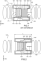
- FIG 1 also shows an arrow 101 symbolizing the optical draw of the eyepiece 180, or in other words the required distance between the intensified image forming surface P2 (here at the output of the optical fiber network 140), and the eyepiece 180 (at an interface 181 of the eyepiece 180 located opposite the conversion element 130).
- the optical draw 101 corresponds to the distance allowing the eyepiece 180 to achieve optical conjugation between the intensified image forming surface P2, and the image surface seen clearly by the user, in use.
- An objective of the present invention is to provide an image intensifier device, capable of having a reduced bulk in comparison with the image intensifier devices according to the prior art.
- the conversion element can also be called a "photon-electron conversion element”.
- each electron incident on the microchannel plate generates the emission of a large number of secondary electrons, preferably more than ten.
- a solution to reduce the bulk of an image intensifier device, of the type shown in figure 1 consists of reducing the length of the optical fiber network. Recent developments have made it possible to produce a fiber network capable of inverting an input image, and having a reduced length while preserving the optical transmission and contrast requirements allowing to provide a compliant image quality.
- FIG 2 illustrates an image intensifier device 100', which does not differ from that of the figure 1 that the optical fiber network 140' has a reduced length.
- the conversion element 130' extends at the input of the optical fiber network, and the intensified image forming surface P2 is located at the output of the optical fiber network 140. Due to the reduced length of the optical fiber network 140', the intensified image forming surface P2 is significantly set back from the output of the housing 190'. In order to maintain the required distance between the intensified image forming surface P2 and the eyepiece 180', it is therefore necessary to bring the housing 190' and the eyepiece 180' closer together.
- the eyepiece 180' may be brought closer to the housing 190', at most up to an extreme position in which the eyepiece 180' is pressed against an exit edge 191' of the housing 190'.
- the exit edge 191' of the housing 190' designates its edge furthest from the objective 170. If the reduction in length of the optical fiber bundle 140' is significant, even in this extreme position it is impossible to obtain that the distance between the intensified image forming surface P2 and the eyepiece 180' is equal to the optical draw 101' of the eyepiece (see figure 2 ).
- the person skilled in the art may then have the idea of reducing the length L of the housing 190', to reduce a distance between the intensified image forming surface P2 and the output edge 191' of the housing 190'. However, he will find himself limited by the size of the power supply module 160'. The obvious solution to overcome this problem is to miniaturize this power supply module 160'.
- the power supply module is moved to a region located on the upstream side of the photocathode in the direction of circulation of the photons and electrons in the image intensifier device (i.e. on the side of the photocathode opposite the microchannel plate).
- This new location makes it possible to bring the intensified image forming surface P2 and the output edge 191' of the housing 190' closer together, without any restriction. It then becomes possible to respect the distance required between the intensified imaging surface and the eyepiece, while having a reduced length of optical fiber bundle.
- the power supply module since the power supply module is relocated rather than miniaturized, it does not need to be completely modified to accommodate miniaturized internal components.
- This new location of the power supply module frees up a space located on the downstream side of the conversion element, according to the direction of circulation of the photons and electrons in the image intensifier device.
- the freeing up of this space makes it possible to reduce the size of the image intensifier device.
- the freeing up of this space makes it possible, for example, to reduce a distance between the conversion element and an ancillary element such as an eyepiece.
- This technical advantage is found in the presence of a bundle of optical fibers downstream of the conversion element, but also in the absence of such a bundle of optical fibers.
- the power supply module extends around the periphery of a lens as described with reference to the figure 1 . Since the objective diameter can be smaller than that of the intensifier tube, a space around the objective can be used to house the power supply module without increasing the overall diameter of the image intensifier device.
- the power supply module extends outside the intensifier tube.
- the device according to the invention further comprises a first set of lenses, called an objective, configured to optically combine a focusing surface located outside the intensifier tube, and a surface of initial image formation located inside or at the entrance of the intensifier tube, and the power supply module extends around the periphery of the objective.
- a first set of lenses called an objective
- the power supply module does not extend beyond the lens, on either side of the latter and along an axis parallel to the optical axis of the latter.
- the power supply module preferably has a through opening that extends opposite the photocathode.
- the power supply module may be ring-shaped.
- the device according to the invention further comprises a bundle of optical fibers, arranged downstream of the conversion element in the direction of propagation of the photons and electrons in the image intensifier device, with the optical fibers of the bundle of optical fibers arranged so as to pivot on itself an image provided at the input of the bundle of optical fibers, and with an output surface of the bundle of optical fibers, on the side opposite the conversion element, which forms a surface called the intensified image formation surface.
- the device according to the invention further comprises a transparent support, with the conversion element formed by a coating covering at least part of one face of said transparent support, and with said face of the transparent support which forms a surface called an intensified image forming surface.
- the device according to the invention may further comprise a second set of lenses, called an eyepiece, configured to optically conjugate the intensified image-forming surface and an image surface located outside the intensifier tube.
- the device according to the invention may further comprise a complementary image-forming module, configured to provide a complementary image, as well as a partially reflective element, which extends between the eyepiece and the intensified image-forming surface and which is configured to superimpose the complementary image and an intensified image formed at the intensified image-forming surface.
- the device according to the invention may further comprise a shift element, configured to laterally shift an intensified image. originating directly or indirectly from the intensified image-forming surface.
- the offset element may be at least partially transparent in the visible, to allow the superposition of the intensified image offset by the offset element, with a transparent view of a surrounding scene.
- the figures show the axes of an orthonormal reference frame (Oxyz).
- the axis (Ox) corresponds to the direction of propagation of light in the image intensifier device according to the invention.
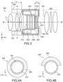
- FIG 3 schematically illustrates, in a sectional view, an image intensifier device 300 according to a first embodiment of the invention.
- the image intensifier device 300 will only be described for its differences relative to the embodiment of the figure 1 .
- the power supply module 360 does not extend around the optical fiber network 340, and the optical fiber network 340 has a reduced length.
- the power supply module 360 here extends around the periphery of the lens 370, in a region located upstream of the photocathode 310, that is to say on the side of the photocathode 310 opposite the microchannel plate 320 and the conversion element 330.
- the photocathode 310, the microchannel plate 320, the conversion element 330 extend inside an intensifier tube 350 as described in the introduction.
- the intensifier tube 350 itself extends, with the optical fiber network 340, inside a housing 390.
- the photocathode 310, the microchannel plate 320 and the conversion element 330 here each extend in planes parallel to the plane (Oyz).
- an output edge 391 is defined on the housing 390, located on the side of the optical fiber network 340 and facing the eyepiece 380.
- the output edge 391 of the housing 390 extends here in a plane (yOz), parallel to the plane of the microchannel plate 320.
- the intensified image-forming surface, P2 as described in the introduction, is located here on the output end of the optical fiber network 340.
- the intensified image-forming surface, P2 is constituted in particular by a surface passing through the output faces of the optical fibers of the optical fiber network 340, on the side of the optical fibers opposite the microchannel plate 320.
- the intensified image-forming surface P2 is here a non-planar surface, the topology of which follows that of a first interface 381 belonging to the eyepiece 380, where said first interface 381 is located on the side of the conversion element 330.
- the power supply module 360 does not extend around the optical fiber network 340, but in a region located upstream of the photocathode 310.
- the output edge 391 of the housing 390 is close to the output end 341 of the optical fiber network 340.
- the output edge 391 of the housing 390 is therefore close to the intensified image forming surface P2.
- the distance between the intensified image forming surface P2 and the first interface 381 belonging to the eyepiece 380 is equal to the optical draw 301 of the eyepiece 380 (as defined in the introduction).
- the power supply module 360 here extends on the periphery of the photocathode 310, in an orthogonal projection of the latter in a plane parallel to the plane (Oyz).
- the optical fiber network 340 protrudes slightly outside the housing 390.
- the intensified image forming surface P2 therefore extends outside the housing 390.
- the power supply module 360 is located here outside the intensifier tube 350 and the housing 390. It has here a length Le, measured along the axis (Ox), strictly less than the length Lb of the objective 370, measured along the same axis. Furthermore, it does not protrude beyond the objective 370, along the axis (Ox) (parallel to the optical axis BB' of the objective 370).
- FIG. 4A illustrates the image intensifier device 300, according to a sectional view in a plane AA' parallel to the plane (yOz) and passing through the power supply module 360.
- the Figure 4A shows that the power supply module 360 surrounds the lens 370, over an angle of 380°.
- the power supply module 360 is provided with a through opening 361, inside which the lens 370 extends.
- the through opening 361 is located opposite the photocathode 310.
- the through opening 361 has the shape of a cylinder of revolution, with an axis of revolution orthogonal to the plane (Oyz) of the photocathode 310 and preferably passing through the center of the latter.
- the power supply module 360 has the shape of a first cylinder of revolution, open at the center by a through opening 361 in the shape of a second cylinder of revolution concentric with the first cylinder of revolution.
- the power supply module 360 has a ring shape.
- the power supply module 360 has any shape, provided with a through opening in the shape of a cylinder of revolution as described above.
- the opening in the center is not in the shape of a cylinder of revolution, but has any shape capable of allowing light to pass through to the photocathode 310.
- the 360' power supply module only surrounds the 370 lens at an angle less than or equal to 180°.
- power supply module can be implemented, without departing from the scope of the invention, in particular forms in which the power supply module is not centered on the optical axis BB'.
- the power supply module 360 does not protrude beyond the housing 390, in an orthogonal projection of the latter in a plane (Oyz).
- the orthogonal projection of the power supply module 360, in a plane (yOz) is inscribed inside the orthogonal projection of the housing 390 in the same plane.
- the maximum diameter of the lens 370 is strictly less than the external diameter of the housing 390, and the power supply module 360 extends in a space delimited by the edge of the lens 370 and a tube of the same diameter as the external diameter of the housing 390. This ensures that the power supply module 360 does not increase a total size of the image intensifier device, in particular a diameter of the image intensifier device.
- the novel arrangement of the power supply module has an advantage, even in the absence of an optical fiber network at the output of the intensifier tube.
- the novel arrangement of the power supply module frees up space for inserting additional elements for adding new functionalities to the image intensifier device, while still taking up less space.
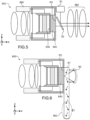
- FIG. 5 illustrates a second embodiment of an image intensifier device 500 according to the invention, in which the space freed by the power supply module Electricity is used to add additional functionality to the device without increasing its footprint.
- the image intensifier device 500 is not distinguished from the embodiment of the figure 3 , in that it does not include a network of optical fibers at the output of the intensifier tube, and in that it includes a means of generating and superimposing a complementary image.
- the complementary image generation and superposition means here comprises a complementary image formation module 51, and a partially reflecting mirror 52.
- the partially reflecting mirror 52 extends between the eyepiece 580 and the intensified image forming surface P2.
- the partially reflecting mirror 52 reflects a portion of the incident light, and transmits another portion of the incident light.
- the partially reflecting mirror 52 is replaced by any other partially reflecting element, for example a splitter cube, or a splitter plate.
- the complementary image formation module 51 is configured to generate a so-called complementary image, and to project the latter towards the partially reflecting mirror 52, here along the axis (Oz).
- the complementary image formation module 51 comprises a display screen, in particular a screen based on OLED (organic light-emitting diodes). It may further comprise a processor, connected to the display screen, and integrating the electronics necessary for controlling and powering said screen, as well as the electronics necessary for exchanging data with the outside (to receive data relating to the complementary image to be displayed on the screen).
- the complementary image formation module 51 extends around the periphery of the partially reflecting mirror 52, and in particular occupies at least part of a region occupied, in the prior art, by the electrical power supply module 560.
- the partially reflecting mirror 52 is configured to superimpose the complementary image, projected by the complementary image forming module 51, and an intensified image formed at the intensified image forming surface P2.
- the complementary image forming module 51 is configured to project a complementary image, arriving at an incidence of 45° on the partially reflecting mirror 52, propagating along the axis (Oz).
- this complementary image is reflected at least partially in the direction of the eyepiece 580.
- the intensified image formed at the output end of the optical fiber bundle 540 arrives at an incidence of 45° on the partially reflecting mirror 52, propagating along the axis (Ox).
- this intensified image is transmitted at least partially in the direction of the eyepiece. Downstream of the partially reflecting mirror 52, in the direction of circulation of the light (and electrons) in the device 500, the complementary image is thus superimposed on the intensified image.
- the complementary image advantageously has dimensions similar to those of the intensified image.
- the complementary image is constituted for example by graphic symbols.
- symbols relating to measurements provided by additional sensors for example display of cardinal points, a targeting reticle, etc. can be superimposed on the intensified image.
- the intensified imaging surface P2 is a planar surface, to simplify the superposition of the intensified image with the complementary image.
- the invention also covers variants in which the intensified imaging surface P2 is a non-planar surface, for example a concave surface.
- FIG. 6 illustrates a third embodiment of an image intensifier device 600 according to the invention, which will only be described for its differences relative to the embodiment of the figure 3 .
- the image intensifier device 600 does not include a network of optical fibers at the output of the intensifier tube, and includes a means of superimposing a real image.
- the real image superposition means here comprises a shift element 61 and a focusing optic 62.
- the shift element 61 here extends between the intensified image forming surface P2 and the focusing optic 62.
- the focusing optics 62 here consist of a concave reflecting mirror, with its optical axis parallel to the axis (Ox) and with its reflecting face located on the side of the intensified image-forming surface P2.
- the focusing optics 62 are configured to project the intensified image P2 formed on the intensified image-forming surface P2 to infinity. Here, the image is projected to infinity, in the direction of the intensified image-forming surface P2.
- the offset element 61 is here attached to the intensified image forming surface P2. This arrangement is made possible by the space freed up by the forward movement of the power supply module.
- the intensified imaging surface P2 is a planar surface, to facilitate surface contact with the offset element 61.
- the offset element 61 here comprises a waveguide, which covers the intensified image formation surface P2, and extends laterally beyond this surface to a so-called observation region RO.
- Said waveguide is provided with injection elements, and extraction elements.
- the injection and extraction elements are constituted for example by respective diffractive elements, etched on the surface of the waveguide.
- the injection elements not shown, extend opposite the intensified image formation surface P2, on the side of the focusing optics.
- the extraction elements, not shown extend here in the observation region RO, on the side of the focusing optics.
- the offset element 61 is at least partially transparent in the visible. For example, it has a transmission coefficient greater than or equal to 95%, over a wavelength range from 400 nm to 700 nm.
- the intensified image formed on the surface P2 propagates to the focusing optics 62, passing right through the offset element 61.
- the light is collimated and returned in the opposite direction.
- the intensified image is projected to infinity and returned in the opposite direction.
- the light returned by the focusing optics 62 thus returns to the offset element 62, at the injection elements as mentioned above.
- the light thus enters the inside of the offset element 62, in the waveguide, and initiates optical guiding there.
- the waveguide the light is guided, along the axis (Oz), to the observation region RO. When it reaches the level of the extraction elements mentioned above, the light is extracted out of the waveguide.
- the extracted light is collimated, like the light initially injected into the waveguide.
- the offset element 61 is therefore configured to receive an intensified image as input, to laterally offset this intensified image so as to bring it to the observation region RO, and to extract this intensified image towards the outside of the offset element 61.
- the intensified image which is laterally offset using the offset element 61 is an image which comes directly or indirectly from the intensified image formation surface P2. Here, it comes indirectly from said surface P2, since it corresponds to the intensified image formed on the surface P2 then projected to infinity by the focusing optics 62.
- the user places his eye with regard to the offset element 61, with regard to the observation region RO, where the intensified image projected to infinity and having circulated in the offset element 61 emerges.
- the user thus visualizes, in superposition, the intensified image brought by the offset element 61, and an exterior scene seen in transparency through the offset element 61.
- the image intensifier device 600 thus forms an augmented reality vision device, to offer a view corresponding to the superposition of an intensified image and an image in natural vision.
- the image intensifier device 600 does not include an eyepiece arranged directly at the output of the optical fiber bundle.
- the offset element 61 is advantageously secured to the optical fiber bundle 640 by direct bonding or proximity coupling to the output face of the latter.
- the focusing optics extend between the intensified image-forming surface P2 and the offset element.
- the focusing optics then consist of one or more refractive lenses.
- the focusing optics are configured to project the intensified image formed on the intensified image-forming surface P2 to infinity.
- the image is projected in direction of the offset element, here on the side of the focusing optics opposite the surface P2.
- the image thus projected to infinity enters the offset element, and is brought to the observation region where it is extracted from the offset element.
- the optical draw of the focusing optics can be very short. The invention then makes it possible to approach the focusing optics sufficiently close to the plane P2, thanks to the space freed by the forward movement of the power supply module.
- the image intensifier device does not comprise the network of optical fibers, but a transparent support such as a glass block.
- the conversion element is in the form of a coating extending in one piece on one face of said transparent support.
- the transparent support is transparent to the wavelength of the photons emitted by the conversion element.
- the intensified image formation surface is then merged with the surface along which the coating forming the conversion element extends, on the transparent support.
- the reversal of the image "right side up" is carried out by refractive optics.
- the intensifier device comprises a bundle of optical fibers, forming an optical input of the intensifier tube on the photocathode side.
- the initial image formation surface, P1 is formed by one end of the bundle of optical fibers, on the side opposite the photocathode.
- This embodiment may or may not be combined with the presence of a bundle of optical fibers at the output of the intensifier tube, on the conversion element side. This embodiment may be combined with each of the examples, variants and embodiments described above.
- the power supply module can be located inside the housing receiving the intensifier tube and the optical fiber bundle.
- the invention also covers a binocular type system, comprising two image intensifier devices according to the invention, each dedicated to a respective eye of the user.
- the device according to the invention finds advantageous use in the field of night vision, for the observation of scenes with little or no light.
Landscapes
- Physics & Mathematics (AREA)
- General Physics & Mathematics (AREA)
- Optics & Photonics (AREA)
- Astronomy & Astrophysics (AREA)
- Image-Pickup Tubes, Image-Amplification Tubes, And Storage Tubes (AREA)
- Telescopes (AREA)
Description
- Le domaine de l'invention est celui des dispositifs intensificateurs d'image, utilisés pour l'observation d'une scène faiblement éclairée, notamment une scène nocturne.
- Un dispositif intensificateur d'image est basé sur le principe d'amplification de la lumière par successivement une conversion photon-électron opérée par une photocathode, une multiplication du nombre des électrons par émission secondaire, et une conversion finale électron-photon opérée par un écran luminescent nommé écran phosphore.
- La
figure 1 illustre de façon schématique un dispositif intensificateur d'image 100 selon l'art antérieur. Le dispositif intensificateur d'image comporte les éléments suivants, agencés les uns à la suite des autres, dans cet ordre : - une photocathode 110;
- une galette de micro-canaux 120, ou MCP pour l'anglais « microchannel plate » ; et
- un élément de conversion électrons-photons 130.
- La photocathode 110 est disposée du côté de l'entrée du dispositif intensificateur d'image 100. En utilisation, elle est polarisée par une première tension de polarisation. Cet étage est apte à convertir un faisceau incident de photons en un faisceau initial d'électrons, par effet photoélectrique.
- La galette de micro-canaux 120 est un composant en verre, traversée par une multitude de micro-canaux. En utilisation, elle est polarisée par une deuxième tension de polarisation. Cet étage permet la multiplication des charges électriques, par émission secondaire. Un champ interne est créé par l'application de ladite deuxième tension de polarisation, appliquée entre les deux faces (entrée et sortie) de la galette de micro-canaux. Lorsqu'un électron entre dans un micro-canal et percute sa paroi, cela provoque l'émission de plusieurs électrons dits secondaires. Les électrons secondaires sont accélérés par le champ interne dans la galette de micro-canaux 120 et percutent à leur tour la paroi du micro-canal, ce qui provoque l'émission de nouveaux électrons secondaires. Il s'agit donc d'un phénomène en cascade. Dans le dispositif intensificateur d'image 100, la galette de micro-canaux 120 est configurée pour recevoir le faisceau d'électrons initial émis par la photocathode 110, et pour envoyer en réponse un faisceau intensifié d'électrons. Chaque électron du faisceau d'électrons initial arrivant de la photocathode génère l'émission d'une pluralité d'électrons du faisceau intensifié d'électrons.
- Dans la suite, l'élément de conversion électron-photon 130 est nommé simplement « élément de conversion ». En utilisation, il est polarisé par une troisième tension de polarisation. Il est configuré pour recevoir le faisceau intensifié d'électrons, et pour émettre en réponse un faisceau intensifié de photons. Chaque électron du faisceau intensifié d'électrons est à l'origine d'un photon respectif du faisceau intensifié de photons. La répartition de lumière dans le faisceau intensifié de photons correspond donc à la répartition de lumière dans le faisceau de photons incident sur la photocathode, fortement amplifiée par l'émission en cascade au niveau de la galette de micro-canaux. Ainsi, une image bas niveau de lumière, fournie au niveau de la photocathode, est transformée en une image de luminosité suffisante pour y distinguer des objets à l'œil nu. L'élément de conversion 130 est constitué de préférence d'un écran phosphore.
- La photocathode 110, la galette de micro-canaux 120 et l'élément de conversion 130 s'étendent les uns à la suite des autres, dans cet ordre, le long de l'axe (Ox). La galette de micro-canaux 120 se trouve donc entre la photocathode 110 et la galette de micro-canaux 120. On peut définir un sens de circulation des photons et des électrons dans le dispositif intensificateur d'image, qui correspond donc ici à l'axe (Ox), orienté de la photocathode 110 vers l'élément de conversion 130.
- Dans tout le texte, les termes « amont » et « aval » se rapportent au sens de circulation des photons et des électrons dans le dispositif intensificateur d'image.
- La photocathode 110, la galette de micro-canaux 120, et l'élément de conversion 130 s'étendent tous les trois à l'intérieur d'une chambre étanche, ou tube intensificateur 150, à l'intérieur de laquelle règle une très basse pression. Le niveau de pression dans le tube intensificateur 150 est nommé « ultra vide » par l'homme du métier. A l'intérieur du tube intensificateur 150 s'étendent ici deux zones 151, 152, sous pression ultra vide. Lesdites zones 151, 152 s'étendent respectivement entre la photocathode 110 et la galette de micro-canaux 120, et entre la galette de micro-canaux 120 et l'élément de conversion 130. Ici, la photocathode 110 est constituée d'un revêtement déposé sur un hublot 111, ledit hublot formant une fenêtre d'entrée du tube intensificateur 150.
- Dans l'exemple illustré à la
figure 1 , le dispositif intensificateur d'image comporte en outre un réseau de fibres optiques 140, qui s'étend en aval de l'élément de conversion 130, de sorte que l'élément de conversion 130 se trouve entre la galette de micro-canaux 120 et le réseau de fibres optiques 140. Le tube intensificateur 140 est alors fermé, à son extrémité opposée à la photocathode 110, par l'une des extrémités du réseau de fibres optiques 140. L'élément de conversion 130 se présente sous la forme d'une multicouche de grains micrométriques luminescents. Chaque grain luminescent s'étend sur une ou plusieurs fibres optiques du réseau de fibres optiques 140, du côté de la galette de micro-canaux 120. - Le réseau de fibres optiques 140 est configuré pour inverser (c'est-à-dire pivoter à 180°), une image fournie en entrée. Dit autrement, une image fournie en entrée du réseau de fibres optiques est pivotée de 180° autour de l'axe (Ox), entre l'entrée et la sortie du réseau de fibres optiques. Ladite image est en outre translatée d'une extrémité à l'autre du réseau de fibres optiques 140, ici le long de l'axe (Ox). L'agencement des fibres optiques à l'entrée du réseau de fibres optiques (du côté de la galette de micro-canaux 120), et l'agencement des fibres optiques à la sortie du réseau de fibres optiques (du côté opposé à la galette de micro-canaux 120), sont symétriques l'un de l'autre selon une symétrie circulaire d'angle 180°=π. Le réseau de fibres optiques 140 permet de pivoter à 180° l'image intensifiée obtenue au niveau de l'élément de conversion 130, de sorte qu'en utilisation elle soit vue « à l'endroit » par l'utilisateur. Il s'agit ainsi de compenser l'inversion d'image apportée par l'objectif 170 mentionné plus loin.
- L'ensemble comportant la photocathode 110, la galette de micro-canaux 120, l'élément de conversion 130, et le réseau de fibres optiques 140, est inséré entre un objectif 170 et un oculaire 180.
- L'objectif 170 est constitué par un ensemble d'une ou plusieurs optiques réfractives, ou lentilles. Il est configuré pour réaliser la conjugaison optique entre une surface de mise au point, ou surface objet, au niveau de laquelle se trouve une scène à observer et/ou imager, et une surface de formation d'image initiale P1 située à l'intérieur ou en entrée du tube intensificateur 150. Ici, la surface de formation d'image initiale P1 s'étend directement sur la photocathode 110, sur la surface active de cette dernière.
- L'oculaire 180 est constitué par un ensemble d'une ou plusieurs optiques réfractives, ou lentilles. Il est configuré pour réaliser la conjugaison optique entre une surface de formation d'image intensifiée P2, et une surface image située à l'extérieur du tube intensificateur 150.
- La surface de formation d'image intensifiée P2 désigne une surface sur laquelle, en utilisation, une image intensifiée est formée par les photons émis par l'élément de conversion 130. Le cas échéant, il s'agit de la surface vérifiant cette condition, et qui est la plus proche de la sortie optique 153 du tube intensificateur 150. La sortie optique 153 du tube intensificateur 150 désigne une interface par où, en utilisation, le faisceau intensifié de photons émis par l'élément de conversion 130 émerge dans l'espace libre. Ici, la sortie optique 153 du tube intensificateur 150 est formée par une extrémité du réseau de fibres optiques 140, du côté opposé à la galette de micro-canaux 120. La surface de formation d'image intensifiée P2 passe alors par les faces de sortie des fibres optiques du réseau de fibres optiques 140, du côté opposé à la galette de micro-canaux 120. L'image intensifiée, formée au niveau de la surface P2, correspond à l'image formée au niveau de l'élément de conversion 130, déportée et pivotée par le réseau de fibres optiques 140.
- La surface image correspond de préférence à une surface vue nette par l'utilisateur, pour un oeil au repos regardant à travers l'oculaire 180. Pour un confort visuel optimal, l'oculaire 180 peut être ajustable en dioptrie. En utilisation, un utilisateur place son oeil derrière l'oculaire 180, du côté opposé au réseau de fibres optiques 140. La surface image et la rétine de l'œil sont alors optiquement conjuguées par un système optique formé par les éléments de l'œil entre la rétine et la cornée, et le cas échéant une optique de correction de la vue telle qu'une lentille de contact. Pour un oeil emmétrope, la surface image s'étend à l'infini.
- Chacun parmi la photocathode 110, la galette de micro-canaux 120, et l'élément de conversion 130, est relié à un module d'alimentation électrique 160, qui lui fournit une tension de polarisation respective (nommée respectivement première, deuxième et troisième tension de polarisation). Le module d'alimentation électrique 160 est relié en entrée à une source électrique basse tension (non représentée), par exemple une pile. Il est configuré pour convertir la basse tension ainsi reçue, en au moins une haute tension formant respectivement les première, deuxième et troisième tensions de polarisation, et pour fournir ces tensions de polarisation à chacun parmi la photocathode 110, la galette de micro-canaux 120, et l'élément de conversion 130.
- Le module d'alimentation électrique 160 et le tube intensificateur 150 s'étendent ensemble à l'intérieur d'un logement 190, généralement en forme de tube.
- Comme illustré à la
figure 1 , le module d'alimentation électrique 160 s'étend autour du réseau de fibres optiques 140. - La
figure 1 montre également une flèche 101 symbolisant le tirage optique de l'oculaire 180, ou en d'autres termes la distance requise entre la surface de formation d'image intensifiée P2 (ici en sortie du réseau de fibres optiques 140), et l'oculaire 180 (au niveau d'une interface 181 de l'oculaire 180 située au regard de l'élément de conversion 130). Le tirage optique 101 correspond à la distance permettant que l'oculaire 180 réalise la conjugaison optique entre la surface de formation d'image intensifiée P2, et la surface image vue nette par l'utilisateur, en utilisation. -
US 2009/108180 A1 etWO 2016/032326 A1 divulguent un dispositif intensificateur d'image selon le préambule de la présente revendication 1. - Un objectif de la présente invention est de proposer un dispositif intensificateur d'image, apte à présenter un encombrement réduit en comparaison avec les dispositifs intensificateurs d'image selon l'art antérieur.
- Cet objectif est atteint avec un dispositif intensificateur d'image selon la revendication 1.
- L'élément de conversion peut également être nommé « élément de conversion photon-électrons ».
- En utilisation, chaque électron incident sur la galette de micro-canaux génère l'émission d'un grand nombre d'électrons secondaires, de préférence plus d'une dizaine.
- Une solution pour réduire l'encombrement d'un dispositif intensificateur d'image, du type de celui représenté en
figure 1 , consiste à réduire la longueur du réseau de fibres optiques. Des développements récents ont permis en effet de réaliser un réseau de fibres apte à inverser une image d'entrée, et présentant une longueur réduite tout en préservant les requis de transmission optique et de contraste permettant de fournir une qualité d'image conforme. - La
figure 2 , ne faisant pas partie de la présente invention, illustre un dispositif intensificateur d'image 100', qui ne diffère de celui de lafigure 1 qu'en ce que le réseau de fibres optiques 140' présente une longueur réduite. Comme dans l'art antérieur, l'élément de conversion 130' s'étend en entrée du réseau de fibres optiques, et la surface de formation d'image intensifiée P2 se trouve au niveau de la sortie du réseau de fibres optiques 140. Du fait de la longueur réduite du réseau de fibres optiques 140', la surface de formation d'image intensifiée P2 se trouve significativement en retrait par rapport à la sortie du logement 190'. Afin de maintenir la distance requise entre la surface de formation d'image intensifiée P2 et l'oculaire 180', il est donc nécessaire de rapprocher le logement 190' et l'oculaire 180'. L'oculaire 180' pourra être rapproché du logement 190', au maximum jusqu'à une position extrême dans laquelle l'oculaire 180' est appuyé contre un bord de sortie 191' du logement 190'. Le bord de sortie 191' du logement 190' désigne son bord le plus éloigné de l'objectif 170. Si la réduction de longueur du faisceau de fibres optiques 140' est importante, même dans cette position extrême il est impossible d'obtenir que la distance entre la surface de formation d'image intensifiée P2 et l'oculaire 180' soit égale au tirage optique 101' de l'oculaire (voirfigure 2 ). L'homme du métier pourra alors avoir l'idée de réduire la longueur L du logement 190', pour diminuer une distance entre la surface de formation d'image intensifiée P2 et le bord de sortie 191' du logement 190'. Cependant, il se trouvera limité par l'encombrement du module d'alimentation électrique 160'. La solution évidente pour palier à ce problème consiste à miniaturiser ce module d'alimentation électrique 160'. - Une idée à la base de l'invention consiste alors à reconsidérer entièrement l'agencement des différents éléments dans le dispositif intensificateur d'image, et à déplacer le module d'alimentation électrique, au lieu de simplement modifier ses dimensions. Selon l'invention, le module d'alimentation électrique est déplacé vers une région située du côté amont de la photocathode selon le sens de circulation des photons et des électrons dans le dispositif intensificateur d'image (c'est-à-dire du côté de la photocathode opposé à la galette de micro-canaux). Ce nouvel emplacement permet de rapprocher la surface de formation d'image intensifiée P2 et le bord de sortie 191' du logement 190', sans aucune restriction. Il devient alors possible de respecter la distance requise entre la surface de formation d'image intensifiée et l'oculaire, tout en ayant un faisceau de fibres optiques de longueur réduite. En outre, puisque le module d'alimentation électrique est déplacé plutôt que miniaturisé, il n'est pas nécessaire que ce dernier soit entièrement modifié pour y intégrer des composants internes miniaturisés.
- Le fait de déplacer le module d'alimentation électrique n'est pas une solution évidente pour l'homme du métier. Ce dernier est plutôt incité à conserver les agencements antérieurs, notamment pour éviter d'avoir à redimensionner les différents logements et capots dans le dispositif intensificateur d'image, et pour éviter d'avoir à reconsidérer des problématiques d'isolation électrique autour du module d'alimentation électrique ainsi que la connectique (fils d'alimentation haute tension conduisant des courants très faibles).
- Ce nouvel emplacement du module d'alimentation électrique libère un espace situé du côté aval de l'élément de conversion, selon le sens de circulation des photons et des électrons dans le dispositif intensificateur d'image. La libération de cet espace permet de diminuer un encombrement du dispositif intensificateur d'image. La libération de cet espace permet par exemple de réduire une distance entre l'élément de conversion et un élément annexe tel qu'un oculaire. Cet avantage technique se retrouve en présence d'un faisceau de fibres optiques en aval de l'élément de conversion, mais également en l'absence d'un tel faisceau de fibres optiques.
- Le module d'alimentation électrique s'étend en périphérie d'un objectif tel que décrit en référence à la
figure 1 . Le diamètre de l'objectif pouvant être inférieur à celui du tube intensificateur, on peut exploiter un espace autour de l'objectif, pour y loger le module d'alimentation électrique sans que cela n'augmente le diamètre total du dispositif intensificateur d'image. - De préférence, le module d'alimentation électrique s'étend à l'extérieur du tube intensificateur.
- Le dispositif selon l'invention comporte en outre un premier ensemble de lentilles, nommé objectif, configuré pour conjuguer optiquement une surface de mise au point située à l'extérieur tube intensificateur, et une surface de formation d'image initiale située à l'intérieur ou en entrée du tube intensificateur, et le module d'alimentation électrique s'étend en périphérie de l'objectif.
- Avantageusement, le module d'alimentation électrique ne dépasse pas au-delà de l'objectif, de part et d'autre de ce dernier et le long d'un axe parallèle à l'axe optique de ce dernier.
- Le module d'alimentation électrique comporte de préférence une ouverture traversante qui s'étend au regard de la photocathode. Le module d'alimentation électrique peut avoir une forme d'anneau.
- Selon un mode de réalisation avantageux, le dispositif selon l'invention comporte en outre un faisceau de fibres optiques, disposé en aval de l'élément de conversion dans le sens de propagation des photons et des électrons dans le dispositif intensificateur d'image, avec les fibres optiques du faisceau de fibres optiques agencées de manière à pivoter sur elle-même une image fournie en entrée du faisceau de fibres optiques, et avec une surface de sortie du faisceau de fibres optiques, du côté opposé à l'élément de conversion, qui forme une surface nommée surface de formation d'image intensifiée.
- Selon un autre mode de réalisation avantageux, le dispositif selon l'invention comporte en outre support transparent, avec l'élément de conversion formé par un revêtement recouvrant une partie au moins d'une face dudit support transparent, et avec ladite face du support transparent qui forme une surface nommée surface de formation d'image intensifiée.
- Le dispositif selon l'invention peut comporter en outre un second ensemble de lentilles, nommé oculaire, configuré pour conjuguer optiquement la surface de formation d'image intensifiée et une surface image située à l'extérieur du tube intensificateur. Le dispositif selon l'invention peut comporter en outre un module de formation d'image complémentaire, configuré pour fournir une image complémentaire, ainsi qu'un élément partiellement réfléchissant, qui s'étend entre l'oculaire et la surface de formation d'image intensifiée et qui est configuré pour superposer l'image complémentaire et une image intensifiée formée au niveau de la surface de formation d'image intensifiée.
- Selon une variante avantageuse, le dispositif selon l'invention peut comporter en outre un élément de déport, configuré pour déporter latéralement une image intensifiée provenant directement ou indirectement de la surface de formation d'image intensifiée. L'élément de déport peut être au moins partiellement transparent dans le visible, pour autoriser la superposition de l'image intensifiée déportée par l'élément de déport, avec une vue en transparence d'une scène environnante.
- La présente invention sera mieux comprise à la lecture de la description d'exemples de réalisation donnés à titre purement indicatif et nullement limitatif, en faisant référence aux dessins annexés sur lesquels :
- [
Fig. 1 ] illustre de manière schématique un dispositif intensificateur d'image selon l'art antérieur; - [
Fig. 2 ] illustre de manière schématique un dispositif intensificateur d'image, ne faisant pas partie de la présente invention, intégrant un réseau de fibres optiques de longueur réduite ; - [
Fig. 3 ] illustre de manière schématique un dispositif intensificateur d'image selon un premier mode de réalisation de l'invention ; - [
Fig. 4A] et [Fig. 4B ] illustrent de manière schématique deux exemples d'agencement du module d'alimentation électrique dans un dispositif intensificateur d'image selon l'invention ; - [
Fig. 5 ] illustre de manière schématique un dispositif intensificateur d'image selon un deuxième mode de réalisation de l'invention ; et - [
Fig. 6 ] illustre de manière schématique un dispositif intensificateur d'image selon un troisième mode de réalisation de l'invention. - Pour plus de clarté, on a représenté sur les figures les axes d'un repère orthonormé (Oxyz). Ici, l'axe (Ox) correspond au sens de propagation de la lumière dans le dispositif intensificateur d'image selon l'invention.
- La
figure 3 illustre de manière schématique, selon une vue en coupe, un dispositif intensificateur d'image 300 selon un premier mode de réalisation de l'invention. Le dispositif intensificateur d'image 300 ne sera décrit que pour ses différences relativement au mode de réalisation de lafigure 1 . - Ici, le module d'alimentation électrique 360 ne s'étend pas autour du réseau de fibres optiques 340, et le réseau de fibres optiques 340 présente une longueur réduite.
- Le module d'alimentation électrique 360 s'étend ici en périphérie de l'objectif 370, dans une région située en amont de la photocathode 310, c'est-à-dire du côté de la photocathode 310 opposé à la galette de micro-canaux 320 et à l'élément de conversion 330.
- Comme précédemment, la photocathode 310, la galette de micro-canaux 320, l'élément de conversion 330 s'étendent à l'intérieur d'un tube intensificateur 350 tel que décrit en introduction. Le tube intensificateur 350 s'étend lui-même, avec le réseau de fibres optiques 340, à l'intérieur d'un logement 390. La photocathode 310, la galette de micro-canaux 320 et l'élément de conversion 330 s'étendent ici chacune dans des plans parallèles au plan (Oyz).
- Comme précédemment, on définit sur le logement 390 un bord de sortie 391, situé du côté du réseau de fibres optiques 340 et faisant face à l'oculaire 380. Le bord de sortie 391 du logement 390 s'étend ici dans un plan (yOz), parallèle au plan de la galette de galette de micro-canaux 320.
- La surface de formation d'image intensifiée, P2, telle que décrite en introduction, est située ici sur l'extrémité de sortie du réseau de fibres optiques 340. La surface de formation d'image intensifiée, P2, est constituée en particulier par une surface passant par les faces de sortie des fibres optiques du réseau de fibres optiques 340, du côté des fibres optiques opposé à la galette de micro-canaux 320. La surface de formation d'image intensifiée P2 est ici une surface non plane, dont la topologie suit celle d'une première interface 381 appartenant à l'oculaire 380, où ladite première interface 381 est située du côté l'élément de conversion 330.
- Le module d'alimentation électrique 360 ne s'étend pas autour du réseau de fibres optiques 340, mais dans une région située en amont de la photocathode 310. Ainsi, même avec une longueur réduite Lf du réseau de fibres optiques 340, le bord de sortie 391 du logement 390 est proche de l'extrémité de sortie 341 du réseau de fibres optiques 340. Le bord de sortie 391 du logement 390 est donc proche de la surface de formation d'image intensifiée P2. Ainsi, malgré un réseau de fibres optiques 340 de longueur réduite Lf, la distance entre la surface de formation d'image intensifiée P2 et la première interface 381 appartenant à l'oculaire 380, est égale au tirage optique 301 de l'oculaire 380 (tel que défini en introduction).
- Le module d'alimentation électrique 360 s'étend ici en périphérie de la photocathode 310, dans une projection orthogonale de ces derniers dans un plan parallèle au plan (Oyz).
- Ici, le réseau de fibres optiques 340 dépasse légèrement à l'extérieur du logement 390. La surface de formation d'image intensifiée P2 s'étend donc à l'extérieur du logement 390.
- Le module d'alimentation électrique 360 est situé ici à l'extérieur du tube intensificateur 350 et du logement 390. Il présente ici une longueur Le, mesurée selon l'axe (Ox), strictement inférieure à la longueur Lb de l'objectif 370, mesurée selon le même axe. En outre, il ne dépasse pas au-delà de l'objectif 370, le long de l'axe (Ox) (parallèle à l'axe optique BB' de l'objectif 370).
- La
figure 4A illustre le dispositif intensificateur d'image 300, selon une vue en coupe dans un plan AA' parallèle au plan (yOz) et passant par le module d'alimentation électrique 360. Lafigure 4A montre que le module d'alimentation électrique 360 entoure l'objectif 370, sur 380° d'angle. Dit autrement, le module d'alimentation électrique 360 est muni d'une ouverture traversante 361, à l'intérieur de laquelle s'étend l'objectif 370. L'ouverture traversante 361 est située au regard de la photocathode 310. De préférence, l'ouverture traversante 361 à la forme d'un cylindre de révolution, d'axe de révolution orthogonal au plan (Oyz) de la photocathode 310 et passant de préférence par le centre de cette dernière. Ici, mais de manière non limitative, le module d'alimentation électrique 360 présente une forme de premier cylindre de révolution, ouvert au centre par une ouverture traversante 361 en forme de second cylindre de révolution concentrique avec le premier cylindre de révolution. Dit autrement, le module d'alimentation électrique 360 a une forme d'anneau. Dans des variantes non représentées, le module d'alimentation électrique 360 a une forme quelconque, munie d'une ouverture traversante en forme de cylindre de révolution tel que décrite ci-dessus. Selon d'autres variantes encore, l'ouverture au centre n'est pas en forme de cylindre de révolution, mais présente une forme quelconque apte à laisser passer la lumière jusqu'à la photocathode 310. - Dans une variante 300' illustrée en
figure 4B , le module d'alimentation électrique 360' n'entoure l'objectif 370 que sur un angle inférieur ou égal à 180°. - De nombreuses autres formes de module d'alimentation électrique peuvent être mises en oeuvre, sans sortir du cadre de l'invention, notamment des formes dans lesquelles le module d'alimentation électrique n'est pas centré sur l'axe optique BB'.
- De préférence, le module d'alimentation électrique 360 ne dépasse pas au-delà du logement 390, dans une projection orthogonale de ces derniers dans un plan(Oyz). Dit autrement, la projection orthogonale du module d'alimentation électrique 360, dans un plan (yOz), est inscrite à l'intérieur de la projection orthogonale du logement 390 dans le même plan. Pour cela, le diamètre maximum de l'objectif 370 est strictement inférieur au diamètre externe du logement 390, et le module d'alimentation électrique 360 s'étend dans un espace délimité par le bord de l'objectif 370 et un tube de même diamètre que le diamètre externe du logement 390. On s'assure ainsi que le module d'alimentation électrique 360 n'augmente pas un encombrement total du dispositif intensificateur d'image, en particulier un diamètre du dispositif intensificateur d'image.
- On décrit dans la suite deux modes de réalisation dans lesquels l'agencement nouveau du module d'alimentation électrique trouve un avantage, même en l'absence d'un réseau de fibres optiques en sortie du tube intensificateur. En particulier, dans ces modes de réalisation, l'agencement nouveau du module d'alimentation électrique libère un espace pour insérer des éléments annexes permettant d'ajouter de nouvelles fonctionnalités au dispositif intensificateur d'image, avec toujours un encombrement réduit.
- La
figure 5 illustre un deuxième mode de réalisation d'un dispositif intensificateur d'image 500 selon l'invention, dans lequel l'espace libéré par le module d'alimentation électrique est exploité pour ajouter des fonctionnalités supplémentaires au dispositif sans augmenter son encombrement. - Le dispositif intensificateur d'image 500 ne se distingue du mode de réalisation de la
figure 3 , qu'en ce qu'il ne comporte pas de réseau de fibres optiques en sortie du tube intensificateur, et en ce qu'il comporte un moyen de génération et de superposition d'image complémentaire. - Le moyen de génération et de superposition d'image complémentaire comporte ici un module de formation d'image complémentaire 51, et un miroir partiellement réfléchissant 52.
- Le miroir partiellement réfléchissant 52 s'étend entre l'oculaire 580 et la surface de formation d'image intensifiée P2. Le miroir partiellement réfléchissant 52 réfléchit une partie de la lumière incidente, et transmet une autre partie de la lumière incidente. Ici, le miroir partiellement réfléchissant 52 est un miroir semi-réfléchissant. Il est incliné d'un angle α relativement au plan (Oyz), avec ici α=45°. Dans des variantes non représentées, le miroir partiellement réfléchissant 52 est remplacé par tout autre élément partiellement réfléchissant, par exemple un cube séparateur, ou une lame séparatrice.
- Le module de formation d'image complémentaire 51 est configuré quant à lui pour générer une image dite complémentaire, et projeter cette dernière en direction du miroir partiellement réfléchissant 52, ici le long de l'axe (Oz). Le module de formation d'image complémentaire 51 comprend un écran d'affichage, notamment un écran à base d'OLED (diodes électroluminescentes organiques). Il peut comprendre en outre un processeur, relié à l'écran d'affichage, et intégrant l'électronique nécessaire au pilotage et à l'alimentation électrique dudit écran, ainsi que l'électronique nécessaire à des échanges de données avec l'extérieur (pour recevoir des données relatives à l'image complémentaire à afficher sur l'écran).
- Le module de formation d'image complémentaire 51 s'étend en périphérie du miroir partiellement réfléchissant 52, et occupe notamment une partie au moins d'une région occupée, dans l'art antérieur, par le module d'alimentation électrique 560.
- Le miroir partiellement réfléchissant 52 est configuré pour superposer l'image complémentaire, projetée par le module de formation d'image complémentaire 51, et une image intensifiée formée au niveau de la surface de formation d'image intensifiée P2. Pour cela, le module de formation d'image complémentaire 51 est configuré pour projeter une image complémentaire, arrivant à incidence 45° sur le miroir partiellement réfléchissant 52, en se propageant selon l'axe (Oz). En utilisation, cette image complémentaire est réfléchie au moins partiellement en direction de l'oculaire 580. De son côté, l'image intensifiée formée à l'extrémité de sortie du faisceau de fibres optiques 540 arrive à incidence 45° sur le miroir partiellement réfléchissant 52, en se propageant selon l'axe (Ox). En utilisation, cette image intensifiée est transmise au moins partiellement en direction de l'oculaire. En aval du miroir partiellement réfléchissant 52, dans le sens de circulation de la lumière (et des électrons) dans le dispositif 500, l'image complémentaire est ainsi superposée à l'image intensifiée.
- L'image complémentaire présente avantageusement de dimensions similaires à celles de l'image intensifiée. L'image complémentaire est constituée par exemple par des symboles graphiques. On peut par exemple superposer à l'image intensifiée, des symboles relatifs à des mesures fournies par des capteurs annexes (par exemple affichage de points cardinaux, d'un réticule de visée, etc).
- Ici, la surface de formation d'image intensifiée P2 est une surface plane, pour simplifier la superposition de l'image intensifiée avec l'image complémentaire. L'invention couvre cependant également des variantes dans lesquelles la surface de formation d'image intensifiée P2 est une surface non plane, par exemple une surface concave.
- La
figure 6 illustre un troisième mode de réalisation d'un dispositif intensificateur d'image 600 selon l'invention, qui ne sera décrit que pour ses différences relativement au mode de réalisation de lafigure 3 . - Dans ce mode de réalisation, le dispositif intensificateur d'image 600 ne comporte pas de réseau de fibres optiques en sortie du tube intensificateur, et comporte un moyen de superposition d'image réelle.
- Le moyen de superposition d'image réelle comporte ici un élément de déport 61, et une optique de focalisation 62. L'élément de déport 61 s'étend ici entre la surface de formation d'image intensifiée P2 et l'optique de focalisation 62.
- L'optique de focalisation 62 est constituée ici d'un miroir réfléchissant concave, avec son axe optique parallèle à l'axe (Ox) et avec sa face réfléchissante située du côté de la surface de formation d'image intensifiée P2. L'optique de focalisation 62 est configurée pour projeter à l'infini l'image intensifiée P2 formée sur la surface de formation d'image intensifiée P2. Ici, l'image est projetée à l'infini, en direction de la surface de formation d'image intensifiée P2.
- L'élément de déport 61 est ici accolé contre la surface de formation d'image intensifiée P2. Cet agencement est rendu possible grâce à l'espace libéré par le déplacement vers l'avant du module d'alimentation électrique.
- Là encore, mais de manière non limitative, la surface de formation d'image intensifiée P2 est une surface plane, pour faciliter le contact surfacique avec l'élément de déport 61.
- L'élément de déport 61 comprend ici par un guide d'onde, qui recouvre la surface de formation d'image intensifiée P2, et dépasse latéralement au-delà de cette surface jusqu'à une région dite d'observation RO. Ledit guide d'onde est muni d'éléments d'injection, et d'éléments d'extraction. Les éléments d'injection et d'extraction sont constitués par exemple par des éléments diffractifs respectifs, gravés en surface du guide d'onde. Ici, les éléments d'injection, non représentés, s'étendent au regard de la surface de formation d'image intensifiée P2, du côté de l'optique de focalisation. En outre, les éléments d'extraction, non représentés, s'étendent ici dans la région d'observation RO, du côté de l'optique de focalisation.
- L'élément de déport 61 est au moins partiellement transparent dans le visible. Il présente par exemple un coefficient de transmission supérieur ou égal à 95%, sur une plage de longueurs d'onde allant de 400 nm à 700 nm.
- En utilisation, l'image intensifiée formée sur la surface P2 se propage jusqu'à l'optique de focalisation 62, en traversant de part en part l'élément de déport 61. Au niveau de l'optique de focalisation, la lumière est collimatée, et renvoyée dans le sens opposé. Dit autrement, l'image intensifiée est projetée à l'infini et renvoyée dans le sens opposé. La lumière renvoyée par l'optique de focalisation 62 revient ainsi sur l'élément de déport 62, au niveau des éléments d'injection tels que mentionnés ci-dessus. La lumière pénètre ainsi à l'intérieur de l'élément de déport 62, dans le guide d'onde, et y amorce un guidage optique. Dans le guide d'onde, la lumière est guidée, le long de l'axe (Oz), jusqu'à la région d'observation RO. Lorsqu'elle parvient au niveau des éléments d'extraction mentionnés ci-avant, la lumière est extraite hors du guide d'onde. La lumière extraite est collimatée, comme la lumière injectée initialement dans le guide d'onde. L'élément de déport 61 est donc configuré pour recevoir en entrée une image intensifiée, pour déporter latéralement cette image intensifiée de manière à l'amener jusqu'à la région d'observation RO, et pour extraire cette image intensifiée vers l'extérieur de l'élément de déport 61. L'image intensifiée qui est déportée latéralement à l'aide de l'élément de déport 61, est une image qui provient directement ou indirectement de la surface de formation d'image intensifiée P2. Ici, elle provient indirectement de ladite surface P2, puisqu'elle correspond à l'image intensifiée formée sur la surface P2 puis projetée à l'infini par l'optique de focalisation 62.
- En utilisation, l'utilisateur place son oeil au regard de l'élément de déport 61, au regard de la région d'observation RO, là où émerge l'image intensifiée projetée à l'infini et ayant circulé dans l'élément de déport 61. L'utilisateur visualise ainsi, en superposition, l'image intensifiée amenée par l'élément de déport 61, et une scène extérieure vue en transparence à travers l'élément de déport 61. Le dispositif intensificateur d'image 600 forme ainsi un dispositif de vision en réalité augmentée, pour offrir une vue correspondant à la superposition d'une image intensifiée et d'une image en vision naturelle.
- Dans ce mode de réalisation, le dispositif intensificateur d'image 600 ne comporte pas d'oculaire disposé directement en sortie du faisceau de fibres optiques.
- L'élément de déport 61 est avantageusement solidarisé du faisceau de fibres optiques 640 par collage direct ou couplage de proximité à la face de sortie de ce dernier.
- Dans une variante non représentée, l'optique de focalisation s'étend entre la surface de formation d'image intensifiée P2 et l'élément de déport. L'optique de focalisation est alors constitué d'une ou plusieurs lentilles réfractives. Là encore, l'optique de focalisation est configurée pour projeter à l'infini l'image intensifiée formée sur la surface de formation d'image intensifiée P2. Là également, l'image est projetée en direction de l'élément de déport, ici du côté de l'optique de focalisation opposé à la surface P2. L'image ainsi projetée à l'infini pénètre dans l'élément de déport, et est amenée jusqu'à la région d'observation où elle est extraite hors de l'élément de déport. Le tirage optique de l'optique de focalisation peut être très court. L'invention permet alors d'approcher l'optique de focalisation suffisamment près du plan P2, grâce à l'espace libéré par le déplacement vers l'avant du module d'alimentation électrique.
- L'invention n'est pas limitée aux exemples décrits ci-dessus. Par exemple, dans une variante non représentée, le dispositif intensificateur d'image ne comporte pas le réseau de fibres optiques, mais un support transparent tel qu'un pavé de verre. Dans ce cas, l'élément de conversion se présente sous la forme d'un revêtement s'étendant d'un seul tenant sur une face dudit support transparent. Le support transparent est transparent à la longueur d'onde des photons émis par l'élément de conversion. La surface de formation d'image intensifiée est alors confondue avec la surface selon laquelle s'étend le revêtement formant élément de conversion, sur le support transparent. Le retournement de l'image « à l'endroit » est réalisé par des optiques réfractives. Les différents modes de réalisation et variantes de l'invention décrits ci-avant peuvent aisément être combinés à cette variante.
- Selon d'autres variantes encore, le dispositif intensificateur comporte un faisceau de fibres optiques, formant une entrée optique du tube intensificateur côté photocathode. Dans ce cas, la surface de formation d'image initiale, P1, telle que mentionnée ci-avant, est formée par une extrémité du faisceau de fibres optiques, du côté opposé à la photocathode. Ce mode de réalisation peut être combiné ou non à la présence d'un faisceau de fibres optiques en sortie du tube intensificateur, côté élément de conversion. Ce mode de réalisation peut être combiné à chacun des exemples, variantes et modes de réalisation décrits ci-dessus.
- Selon d'autres variantes encore, le module d'alimentation électrique peut être situé à l'intérieur du logement recevant le tube intensificateur et le faisceau de fibres optiques.
- L'invention couvre également un système de type jumelle, comportant deux dispositifs intensificateurs d'image selon l'invention, dédiés chacun à un oeil respectif de l'utilisateur.
- Le dispositif selon l'invention trouve une utilisation avantageuse dans le domaine de la vision nocturne, pour l'observation de scènes peu ou pas éclairées.
Claims (10)
- Dispositif intensificateur d'image (300 ; 300' ; 500 ; 600) qui comprend un tube intensificateur (350) et un module d'alimentation électrique (360 ; 360' ; 560), dans lequel le tube intensificateur (350) comporte :- au moins une photocathode (310), configurée pour convertir un faisceau incident de photons en un faisceau initial d'électrons ;- une galette de micro-canaux (320), configurée pour, en utilisation, générer une pluralité d'électrons secondaires en réponse à la réception d'un électron incident, et configurée pour recevoir ledit faisceau initial d'électrons et pour générer en réponse un faisceau intensifié d'électrons ; et- un élément de conversion (330 ; 530), configuré pour recevoir le faisceau intensifié d'électrons et pour émettre en réponse un faisceau intensifié de photons, avec la galette de micro-canaux (320) située entre la photocathode (310) et l'élément de conversion (330 ; 530) ;- un premier ensemble de lentilles (370), nommé objectif, configuré pour conjuguer optiquement une surface de mise au point située à l'extérieur tube intensificateur (350), et une surface de formation d'image initiale (P1) située à l'intérieur ou en entrée du tube intensificateur (350) ;le module d'alimentation électrique (360 ; 360' ; 560) étant configuré pour fournir au moins une tension de polarisation respective, à chacun parmi la photocathode (310), la galette de micro-canaux (320), et l'élément de conversion (330 ; 530);caractérisé en ce que le module d'alimentation électrique (360 ; 360' ; 560) s'étend entièrement dansune région entièrement située en amont de la photocathode (310), du côté de la photocathode opposé à la galette de micro-canaux, en périphérie de l'objectif (370)
- Dispositif (300 ; 300' ; 500 ; 600) selon la revendication 1, caractérisé en ce que le module d'alimentation électrique (360 ; 360' ; 560) ne dépasse pas au-delà de l'objectif (370), de part et d'autre de ce dernier et le long d'un axe parallèle à l'axe optique (BB') de ce dernier.
- Dispositif (300 ; 500 ; 600) selon l'une quelconque des revendications 1 ou 2, caractérisé en ce que le module d'alimentation électrique (360 ; 560) comporte une ouverture traversante (361) qui s'étend au regard de la photocathode (310).
- Dispositif (300 ; 500 ; 600) selon la revendication 3, caractérisé en ce que le module d'alimentation électrique (360 ; 560) a une forme d'anneau.
- Dispositif (300 ; 300' ; 500 ; 600) selon l'une quelconque des revendications 1 à 4, caractérisé en ce qu'il comporte en outre un faisceau de fibres optiques (340 ; 540 ; 640), disposé en aval de l'élément de conversion (330 ; 530) dans le sens de propagation des photons et des électrons dans le dispositif intensificateur d'image, avec les fibres optiques du faisceau de fibres optiques (340 ; 540 ; 640) agencées de manière à pivoter sur elle-même une image fournie en entrée du faisceau de fibres optiques, et avec une surface de sortie du faisceau de fibres optiques, du côté opposé à l'élément de conversion (330 ; 530), qui forme une surface nommée surface de formation d'image intensifiée (P2).
- Dispositif selon l'une quelconque des revendications 1 à 4, caractérisé en ce qu'il comporte en outre un support transparent, l'élément de conversion étant formé par un revêtement recouvrant une partie au moins d'une face dudit support transparent, et une autre face du support transparent formant une surface nommée surface de formation d'image intensifiée.
- Dispositif (300 ; 300' ; 500) selon la revendication 5 ou 6, caractérisé en ce qu'il comporte en outre un second ensemble de lentilles (380 ; 580), nommé oculaire, configuré pour conjuguer optiquement la surface de formation d'image intensifiée (P2) et une surface image située à l'extérieur du tube intensificateur (350).
- Dispositif (500) selon la revendication 7, caractérisé en ce qu'il comporte en outre un module de formation d'image complémentaire (51), configuré pour fournir une image complémentaire, ainsi qu'un élément partiellement réfléchissant (52), qui s'étend entre l'oculaire et la surface de formation d'image intensifiée (P2) et qui est configuré pour superposer l'image complémentaire et une image intensifiée formée au niveau de la surface de formation d'image intensifiée (P2).
- Dispositif (600) selon la revendication 5 ou 6, caractérisé en ce qu'il comporte en outre un élément de déport (61), configuré pour déporter latéralement une image intensifiée provenant directement ou indirectement de la surface de formation d'image intensifiée (P2).
- Dispositif (600) selon la revendication 9, caractérisé en ce que l'élément de déport (61) est au moins partiellement transparent dans le visible, pour autoriser la superposition de l'image intensifiée déportée par l'élément de déport, avec une vue en transparence d'une scène environnante.
Priority Applications (1)
| Application Number | Priority Date | Filing Date | Title |
|---|---|---|---|
| RS20241210A RS66102B1 (sr) | 2021-02-02 | 2022-01-31 | Uređaj za pojačavanje slike sa napajanjem postavljenim uzvodno od fotokatode |
Applications Claiming Priority (2)
| Application Number | Priority Date | Filing Date | Title |
|---|---|---|---|
| FR2100975A FR3119486B1 (fr) | 2021-02-02 | 2021-02-02 | Dispositif intensificateur d’image avec alimentation déportée. |
| PCT/FR2022/050167 WO2022167749A1 (fr) | 2021-02-02 | 2022-01-31 | Dispositif intensificateur d'image avec alimentation disposée en amont de la photocathode |
Publications (2)
| Publication Number | Publication Date |
|---|---|
| EP4275222A1 EP4275222A1 (fr) | 2023-11-15 |
| EP4275222B1 true EP4275222B1 (fr) | 2024-10-30 |
Family
ID=76034696
Family Applications (1)
| Application Number | Title | Priority Date | Filing Date |
|---|---|---|---|
| EP22704936.8A Active EP4275222B1 (fr) | 2021-02-02 | 2022-01-31 | Dispositif intensificateur d'image avec alimentation disposée en amont de la photocathode |
Country Status (10)
| Country | Link |
|---|---|
| US (1) | US11967480B2 (fr) |
| EP (1) | EP4275222B1 (fr) |
| JP (1) | JP7714666B2 (fr) |
| KR (1) | KR20230137373A (fr) |
| CN (1) | CN117121149A (fr) |
| CA (1) | CA3206942A1 (fr) |
| FR (1) | FR3119486B1 (fr) |
| IL (1) | IL304899B2 (fr) |
| RS (1) | RS66102B1 (fr) |
| WO (1) | WO2022167749A1 (fr) |
Families Citing this family (1)
| Publication number | Priority date | Publication date | Assignee | Title |
|---|---|---|---|---|
| FR3128796B1 (fr) * | 2021-10-29 | 2023-10-13 | Photonis France S A S | Dispositif de vision nocturne avec afficheur intégré |
Family Cites Families (10)
| Publication number | Priority date | Publication date | Assignee | Title |
|---|---|---|---|---|
| US4417814A (en) * | 1980-09-23 | 1983-11-29 | Litton Systems, Inc. | Night sight with illuminated aiming point |
| JPS6017418A (ja) * | 1983-07-08 | 1985-01-29 | Hamamatsu Photonics Kk | 可視像と特定波長成分により形成される像を重ねて観察する装置 |
| US5305142A (en) * | 1992-03-06 | 1994-04-19 | Itt Corporation | Replacement assembly for an image intensifier tube |
| US7696462B2 (en) * | 2007-10-30 | 2010-04-13 | Saldana Michael R | Advanced image intensifier assembly |
| FR2925218B1 (fr) * | 2007-12-13 | 2010-03-12 | Photonis France | Tube intensificateur d'image a encombrement reduit et systeme de vision nocturne equipe d'un tel tube |
| CN201740465U (zh) | 2010-08-17 | 2011-02-09 | 福州开发区鸿发光电子技术有限公司 | 一种微光夜视枪用瞄准镜 |
| US9136085B2 (en) * | 2012-05-30 | 2015-09-15 | Hvm Technology, Inc. | Shock-resistant image intensifier |
| NL2013386B1 (en) * | 2014-08-29 | 2016-09-26 | Photonis Netherlands B V | A light-weight image intensifier sensor as well as a power supply for such a light-weight image intensifier sensor and a low-light imaging device comprising such a light-weight image intensifier sensor. |
| FR3097658B1 (fr) * | 2019-06-20 | 2022-07-08 | Photonis France | Appareil de vision offrant une vision nocturne et une vision directe d'une scène environnante |
| CN111751976A (zh) * | 2020-07-07 | 2020-10-09 | 北方夜视技术股份有限公司 | 一种具有通用型连接结构的便携微光夜视仪 |
-
2021
- 2021-02-02 FR FR2100975A patent/FR3119486B1/fr active Active
-
2022
- 2022-01-31 EP EP22704936.8A patent/EP4275222B1/fr active Active
- 2022-01-31 IL IL304899A patent/IL304899B2/en unknown
- 2022-01-31 WO PCT/FR2022/050167 patent/WO2022167749A1/fr not_active Ceased
- 2022-01-31 CN CN202280027064.3A patent/CN117121149A/zh active Pending
- 2022-01-31 JP JP2023547117A patent/JP7714666B2/ja active Active
- 2022-01-31 KR KR1020237028361A patent/KR20230137373A/ko active Pending
- 2022-01-31 CA CA3206942A patent/CA3206942A1/fr active Pending
- 2022-01-31 US US18/263,790 patent/US11967480B2/en active Active
- 2022-01-31 RS RS20241210A patent/RS66102B1/sr unknown
Also Published As
| Publication number | Publication date |
|---|---|
| KR20230137373A (ko) | 2023-10-04 |
| JP7714666B2 (ja) | 2025-07-29 |
| WO2022167749A1 (fr) | 2022-08-11 |
| US11967480B2 (en) | 2024-04-23 |
| US20240105413A1 (en) | 2024-03-28 |
| EP4275222A1 (fr) | 2023-11-15 |
| RS66102B1 (sr) | 2024-11-29 |
| CA3206942A1 (fr) | 2022-08-11 |
| AU2022215903A1 (en) | 2023-08-24 |
| IL304899B1 (en) | 2024-11-01 |
| FR3119486A1 (fr) | 2022-08-05 |
| JP2024507459A (ja) | 2024-02-20 |
| FR3119486B1 (fr) | 2023-03-31 |
| IL304899A (en) | 2023-10-01 |
| AU2022215903A9 (en) | 2024-05-09 |
| IL304899B2 (en) | 2025-03-01 |
| CN117121149A (zh) | 2023-11-24 |
Similar Documents
| Publication | Publication Date | Title |
|---|---|---|
| CA2701993C (fr) | Dispositif d'imagerie modulaire, module pour ce dispositif et procede m is en oeuvre par ce dispositif | |
| EP2277074B1 (fr) | Lunettes informatives | |
| FR2581459A1 (fr) | Dispositif de transport et de combinaison d'images lumineuses, et son utilisation pour un viseur de casque | |
| WO2007128909A1 (fr) | Tete optique miniaturisee a haute resolution spatiale et haute sensibilite, notamment pour l'imagerie de fluorescence confocale fibree | |
| EP3439529A1 (fr) | Dispositifs et méthodes de transport et de contrôle de faisceaux lumineux pour l'imagerie endo-microscopique sans lentille | |
| FR2849218A1 (fr) | Tete optique confocale, notamment miniature, a balayage integre et systeme d'imagerie confocale mettant en oeuvre ladite tete | |
| EP1712940B1 (fr) | Dispositif d'illumination homogène comportant une matrice de diodes laser | |
| WO2022167749A1 (fr) | Dispositif intensificateur d'image avec alimentation disposée en amont de la photocathode | |
| FR2904435A1 (fr) | Sonde endoscopique integrant un objectif ayant un encombrement reduit | |
| EP3420326B1 (fr) | Dispositif d'eclairage pour dispositif de prise de teinte d'une dent, dispositif de prise de teinte integrant ledit dispositif d'eclairage | |
| CA3128728C (fr) | Injection d'un faisceau de rayonnement dans une fibre optique | |
| EP4291937A1 (fr) | Système et procédé d'observation | |
| CA2401328A1 (fr) | Relais optique correcteur d'aberrations pour systeme optique, notamment telescope a miroirs | |
| FR3100896A1 (fr) | Appareil et procédé pour la capture d’image d’un objet observé | |
| EP1808665B1 (fr) | Appareil de visée télémétrique laser | |
| EP0614103B1 (fr) | Lunette à miroirs oscillants pour la vision infrarouge | |
| WO2025133484A1 (fr) | Tube intensificateur d'images couleur et dispositif de vision nocturne en couleur associe | |
| FR2555766A1 (fr) | Structure de coupleurs optiques pour au moins une fibre optique | |
| FR3154165A1 (fr) | Système d’éclairage à large spectre | |
| FR2701831A1 (fr) | Dispositif optique pour la radiographie dentaire. | |
| FR2860078A1 (fr) | Dispositif de pointage optique multi-spectral | |
| WO2003019737A2 (fr) | Source laser en optique guidee | |
| CA2995406A1 (fr) | Laser terahertz, source terahertz et utilisation d'un tel laser terahertz | |
| FR2814581A1 (fr) | Dispositif autonome d'affichage lumineux publicitaire |
Legal Events
| Date | Code | Title | Description |
|---|---|---|---|
| STAA | Information on the status of an ep patent application or granted ep patent |
Free format text: STATUS: UNKNOWN |
|
| STAA | Information on the status of an ep patent application or granted ep patent |
Free format text: STATUS: THE INTERNATIONAL PUBLICATION HAS BEEN MADE |
|
| PUAI | Public reference made under article 153(3) epc to a published international application that has entered the european phase |
Free format text: ORIGINAL CODE: 0009012 |
|
| STAA | Information on the status of an ep patent application or granted ep patent |
Free format text: STATUS: REQUEST FOR EXAMINATION WAS MADE |
|
| 17P | Request for examination filed |
Effective date: 20230804 |
|
| AK | Designated contracting states |
Kind code of ref document: A1 Designated state(s): AL AT BE BG CH CY CZ DE DK EE ES FI FR GB GR HR HU IE IS IT LI LT LU LV MC MK MT NL NO PL PT RO RS SE SI SK SM TR |
|
| DAV | Request for validation of the european patent (deleted) | ||
| DAX | Request for extension of the european patent (deleted) | ||
| GRAP | Despatch of communication of intention to grant a patent |
Free format text: ORIGINAL CODE: EPIDOSNIGR1 |
|
| STAA | Information on the status of an ep patent application or granted ep patent |
Free format text: STATUS: GRANT OF PATENT IS INTENDED |
|
| RIC1 | Information provided on ipc code assigned before grant |
Ipc: G02B 25/00 20060101ALI20240724BHEP Ipc: H01J 29/06 20060101ALI20240724BHEP Ipc: G02B 23/12 20060101ALI20240724BHEP Ipc: H01J 31/50 20060101AFI20240724BHEP |
|
| RIN1 | Information on inventor provided before grant (corrected) |
Inventor name: FERNANDEZ GUTIERREZ, DAVID Inventor name: RODRIGUEZ-PEREZ, DIEGO Inventor name: DE LA TORRE NOETZEL, JORGE Inventor name: LAURENT, NICOLAS |
|
| INTG | Intention to grant announced |
Effective date: 20240814 |
|
| RAP3 | Party data changed (applicant data changed or rights of an application transferred) |
Owner name: PHOTONIS FRANCE |
|
| GRAS | Grant fee paid |
Free format text: ORIGINAL CODE: EPIDOSNIGR3 |
|
| GRAA | (expected) grant |
Free format text: ORIGINAL CODE: 0009210 |
|
| STAA | Information on the status of an ep patent application or granted ep patent |
Free format text: STATUS: THE PATENT HAS BEEN GRANTED |
|
| AK | Designated contracting states |
Kind code of ref document: B1 Designated state(s): AL AT BE BG CH CY CZ DE DK EE ES FI FR GB GR HR HU IE IS IT LI LT LU LV MC MK MT NL NO PL PT RO RS SE SI SK SM TR |
|
| REG | Reference to a national code |
Ref country code: GB Ref legal event code: FG4D Free format text: NOT ENGLISH |
|
| REG | Reference to a national code |
Ref country code: CH Ref legal event code: EP |
|
| REG | Reference to a national code |
Ref country code: NL Ref legal event code: FP |
|
| P01 | Opt-out of the competence of the unified patent court (upc) registered |
Free format text: CASE NUMBER: APP_53710/2024 Effective date: 20240927 |
|
| REG | Reference to a national code |
Ref country code: IE Ref legal event code: FG4D Free format text: LANGUAGE OF EP DOCUMENT: FRENCH |
|
| REG | Reference to a national code |
Ref country code: DE Ref legal event code: R096 Ref document number: 602022007269 Country of ref document: DE |
|
| REG | Reference to a national code |
Ref country code: LT Ref legal event code: MG9D |
|
| PG25 | Lapsed in a contracting state [announced via postgrant information from national office to epo] |
Ref country code: IS Free format text: LAPSE BECAUSE OF FAILURE TO SUBMIT A TRANSLATION OF THE DESCRIPTION OR TO PAY THE FEE WITHIN THE PRESCRIBED TIME-LIMIT Effective date: 20250228 Ref country code: PT Free format text: LAPSE BECAUSE OF FAILURE TO SUBMIT A TRANSLATION OF THE DESCRIPTION OR TO PAY THE FEE WITHIN THE PRESCRIBED TIME-LIMIT Effective date: 20250228 Ref country code: HR Free format text: LAPSE BECAUSE OF FAILURE TO SUBMIT A TRANSLATION OF THE DESCRIPTION OR TO PAY THE FEE WITHIN THE PRESCRIBED TIME-LIMIT Effective date: 20241030 |
|
| PG25 | Lapsed in a contracting state [announced via postgrant information from national office to epo] |
Ref country code: FI Free format text: LAPSE BECAUSE OF FAILURE TO SUBMIT A TRANSLATION OF THE DESCRIPTION OR TO PAY THE FEE WITHIN THE PRESCRIBED TIME-LIMIT Effective date: 20241030 |
|
| REG | Reference to a national code |
Ref country code: AT Ref legal event code: MK05 Ref document number: 1737795 Country of ref document: AT Kind code of ref document: T Effective date: 20241030 |
|
| PG25 | Lapsed in a contracting state [announced via postgrant information from national office to epo] |
Ref country code: BG Free format text: LAPSE BECAUSE OF FAILURE TO SUBMIT A TRANSLATION OF THE DESCRIPTION OR TO PAY THE FEE WITHIN THE PRESCRIBED TIME-LIMIT Effective date: 20241030 |
|
| PG25 | Lapsed in a contracting state [announced via postgrant information from national office to epo] |
Ref country code: ES Free format text: LAPSE BECAUSE OF FAILURE TO SUBMIT A TRANSLATION OF THE DESCRIPTION OR TO PAY THE FEE WITHIN THE PRESCRIBED TIME-LIMIT Effective date: 20241030 |
|
| PG25 | Lapsed in a contracting state [announced via postgrant information from national office to epo] |
Ref country code: NO Free format text: LAPSE BECAUSE OF FAILURE TO SUBMIT A TRANSLATION OF THE DESCRIPTION OR TO PAY THE FEE WITHIN THE PRESCRIBED TIME-LIMIT Effective date: 20250130 |
|
| PG25 | Lapsed in a contracting state [announced via postgrant information from national office to epo] |
Ref country code: AT Free format text: LAPSE BECAUSE OF FAILURE TO SUBMIT A TRANSLATION OF THE DESCRIPTION OR TO PAY THE FEE WITHIN THE PRESCRIBED TIME-LIMIT Effective date: 20241030 Ref country code: GR Free format text: LAPSE BECAUSE OF FAILURE TO SUBMIT A TRANSLATION OF THE DESCRIPTION OR TO PAY THE FEE WITHIN THE PRESCRIBED TIME-LIMIT Effective date: 20250131 Ref country code: LV Free format text: LAPSE BECAUSE OF FAILURE TO SUBMIT A TRANSLATION OF THE DESCRIPTION OR TO PAY THE FEE WITHIN THE PRESCRIBED TIME-LIMIT Effective date: 20241030 |
|
| PG25 | Lapsed in a contracting state [announced via postgrant information from national office to epo] |
Ref country code: SM Free format text: LAPSE BECAUSE OF FAILURE TO SUBMIT A TRANSLATION OF THE DESCRIPTION OR TO PAY THE FEE WITHIN THE PRESCRIBED TIME-LIMIT Effective date: 20241030 |
|
| PG25 | Lapsed in a contracting state [announced via postgrant information from national office to epo] |
Ref country code: DK Free format text: LAPSE BECAUSE OF FAILURE TO SUBMIT A TRANSLATION OF THE DESCRIPTION OR TO PAY THE FEE WITHIN THE PRESCRIBED TIME-LIMIT Effective date: 20241030 |
|
| PG25 | Lapsed in a contracting state [announced via postgrant information from national office to epo] |
Ref country code: EE Free format text: LAPSE BECAUSE OF FAILURE TO SUBMIT A TRANSLATION OF THE DESCRIPTION OR TO PAY THE FEE WITHIN THE PRESCRIBED TIME-LIMIT Effective date: 20241030 |
|
| PG25 | Lapsed in a contracting state [announced via postgrant information from national office to epo] |
Ref country code: RO Free format text: LAPSE BECAUSE OF FAILURE TO SUBMIT A TRANSLATION OF THE DESCRIPTION OR TO PAY THE FEE WITHIN THE PRESCRIBED TIME-LIMIT Effective date: 20241030 |
|
| PG25 | Lapsed in a contracting state [announced via postgrant information from national office to epo] |
Ref country code: SK Free format text: LAPSE BECAUSE OF FAILURE TO SUBMIT A TRANSLATION OF THE DESCRIPTION OR TO PAY THE FEE WITHIN THE PRESCRIBED TIME-LIMIT Effective date: 20241030 |
|
| PG25 | Lapsed in a contracting state [announced via postgrant information from national office to epo] |
Ref country code: CZ Free format text: LAPSE BECAUSE OF FAILURE TO SUBMIT A TRANSLATION OF THE DESCRIPTION OR TO PAY THE FEE WITHIN THE PRESCRIBED TIME-LIMIT Effective date: 20241030 |
|
| PG25 | Lapsed in a contracting state [announced via postgrant information from national office to epo] |
Ref country code: IT Free format text: LAPSE BECAUSE OF FAILURE TO SUBMIT A TRANSLATION OF THE DESCRIPTION OR TO PAY THE FEE WITHIN THE PRESCRIBED TIME-LIMIT Effective date: 20241030 |
|
| REG | Reference to a national code |
Ref country code: DE Ref legal event code: R097 Ref document number: 602022007269 Country of ref document: DE |
|
| REG | Reference to a national code |
Ref country code: CH Ref legal event code: PL |
|
| PLBE | No opposition filed within time limit |
Free format text: ORIGINAL CODE: 0009261 |
|
| STAA | Information on the status of an ep patent application or granted ep patent |
Free format text: STATUS: NO OPPOSITION FILED WITHIN TIME LIMIT |
|
| PG25 | Lapsed in a contracting state [announced via postgrant information from national office to epo] |
Ref country code: SE Free format text: LAPSE BECAUSE OF FAILURE TO SUBMIT A TRANSLATION OF THE DESCRIPTION OR TO PAY THE FEE WITHIN THE PRESCRIBED TIME-LIMIT Effective date: 20241030 |
|
| PG25 | Lapsed in a contracting state [announced via postgrant information from national office to epo] |
Ref country code: LU Free format text: LAPSE BECAUSE OF NON-PAYMENT OF DUE FEES Effective date: 20250131 Ref country code: MC Free format text: LAPSE BECAUSE OF FAILURE TO SUBMIT A TRANSLATION OF THE DESCRIPTION OR TO PAY THE FEE WITHIN THE PRESCRIBED TIME-LIMIT Effective date: 20241030 |
|
| 26N | No opposition filed |
Effective date: 20250731 |
|
| PG25 | Lapsed in a contracting state [announced via postgrant information from national office to epo] |
Ref country code: BE Free format text: LAPSE BECAUSE OF NON-PAYMENT OF DUE FEES Effective date: 20250131 |
|
| PG25 | Lapsed in a contracting state [announced via postgrant information from national office to epo] |
Ref country code: CH Free format text: LAPSE BECAUSE OF NON-PAYMENT OF DUE FEES Effective date: 20250131 |
|
| REG | Reference to a national code |
Ref country code: BE Ref legal event code: MM Effective date: 20250131 |
|
| PGFP | Annual fee paid to national office [announced via postgrant information from national office to epo] |
Ref country code: NL Payment date: 20251230 Year of fee payment: 5 |
|
| PG25 | Lapsed in a contracting state [announced via postgrant information from national office to epo] |
Ref country code: IE Free format text: LAPSE BECAUSE OF NON-PAYMENT OF DUE FEES Effective date: 20250131 |
|
| PGFP | Annual fee paid to national office [announced via postgrant information from national office to epo] |
Ref country code: PL Payment date: 20251229 Year of fee payment: 5 |
|
| PGFP | Annual fee paid to national office [announced via postgrant information from national office to epo] |
Ref country code: RS Payment date: 20251230 Year of fee payment: 5 |
|
| REG | Reference to a national code |
Ref country code: DE Ref legal event code: R082 Ref document number: 602022007269 Country of ref document: DE Representative=s name: VUILLERMOZ, BRUNO, FR |
|
| PGFP | Annual fee paid to national office [announced via postgrant information from national office to epo] |
Ref country code: GB Payment date: 20260127 Year of fee payment: 5 |
|
| PGFP | Annual fee paid to national office [announced via postgrant information from national office to epo] |
Ref country code: DE Payment date: 20260114 Year of fee payment: 5 |
|
| PGFP | Annual fee paid to national office [announced via postgrant information from national office to epo] |
Ref country code: FR Payment date: 20260127 Year of fee payment: 5 |
|
| PGFP | Annual fee paid to national office [announced via postgrant information from national office to epo] |
Ref country code: TR Payment date: 20260128 Year of fee payment: 5 |