EP4274230A2 - Bildverarbeitungsvorrichtung und bildverarbeitungsverfahren - Google Patents
Bildverarbeitungsvorrichtung und bildverarbeitungsverfahren Download PDFInfo
- Publication number
- EP4274230A2 EP4274230A2 EP23190099.4A EP23190099A EP4274230A2 EP 4274230 A2 EP4274230 A2 EP 4274230A2 EP 23190099 A EP23190099 A EP 23190099A EP 4274230 A2 EP4274230 A2 EP 4274230A2
- Authority
- EP
- European Patent Office
- Prior art keywords
- weight matrix
- diagram illustrating
- intra prediction
- unit
- generation method
- Prior art date
- Legal status (The legal status is an assumption and is not a legal conclusion. Google has not performed a legal analysis and makes no representation as to the accuracy of the status listed.)
- Pending
Links
- 238000012545 processing Methods 0.000 title claims abstract description 95
- 238000003672 processing method Methods 0.000 title claims abstract description 12
- 239000011159 matrix material Substances 0.000 claims abstract description 370
- 238000000034 method Methods 0.000 claims description 281
- 230000008569 process Effects 0.000 claims description 58
- 238000005516 engineering process Methods 0.000 abstract description 30
- 238000010586 diagram Methods 0.000 description 262
- 238000013139 quantization Methods 0.000 description 56
- 230000002441 reversible effect Effects 0.000 description 41
- 238000004364 calculation method Methods 0.000 description 38
- 230000003044 adaptive effect Effects 0.000 description 35
- 230000008707 rearrangement Effects 0.000 description 18
- 238000009825 accumulation Methods 0.000 description 17
- 238000006243 chemical reaction Methods 0.000 description 16
- 230000006870 function Effects 0.000 description 9
- 230000000694 effects Effects 0.000 description 5
- 238000004891 communication Methods 0.000 description 4
- PXFBZOLANLWPMH-UHFFFAOYSA-N 16-Epiaffinine Natural products C1C(C2=CC=CC=C2N2)=C2C(=O)CC2C(=CC)CN(C)C1C2CO PXFBZOLANLWPMH-UHFFFAOYSA-N 0.000 description 3
- 230000005540 biological transmission Effects 0.000 description 3
- 230000008859 change Effects 0.000 description 3
- 238000012360 testing method Methods 0.000 description 3
- 238000012935 Averaging Methods 0.000 description 2
- 230000014509 gene expression Effects 0.000 description 1
- 230000010354 integration Effects 0.000 description 1
- 239000004973 liquid crystal related substance Substances 0.000 description 1
- 230000003287 optical effect Effects 0.000 description 1
- 230000008520 organization Effects 0.000 description 1
- 230000001151 other effect Effects 0.000 description 1
- 239000004065 semiconductor Substances 0.000 description 1
- 230000009466 transformation Effects 0.000 description 1
Images


Classifications
-
- H—ELECTRICITY
- H04—ELECTRIC COMMUNICATION TECHNIQUE
- H04N—PICTORIAL COMMUNICATION, e.g. TELEVISION
- H04N19/00—Methods or arrangements for coding, decoding, compressing or decompressing digital video signals
- H04N19/85—Methods or arrangements for coding, decoding, compressing or decompressing digital video signals using pre-processing or post-processing specially adapted for video compression
- H04N19/88—Methods or arrangements for coding, decoding, compressing or decompressing digital video signals using pre-processing or post-processing specially adapted for video compression involving rearrangement of data among different coding units, e.g. shuffling, interleaving, scrambling or permutation of pixel data or permutation of transform coefficient data among different blocks
-
- H—ELECTRICITY
- H04—ELECTRIC COMMUNICATION TECHNIQUE
- H04N—PICTORIAL COMMUNICATION, e.g. TELEVISION
- H04N19/00—Methods or arrangements for coding, decoding, compressing or decompressing digital video signals
- H04N19/50—Methods or arrangements for coding, decoding, compressing or decompressing digital video signals using predictive coding
- H04N19/593—Methods or arrangements for coding, decoding, compressing or decompressing digital video signals using predictive coding involving spatial prediction techniques
-
- H—ELECTRICITY
- H04—ELECTRIC COMMUNICATION TECHNIQUE
- H04N—PICTORIAL COMMUNICATION, e.g. TELEVISION
- H04N19/00—Methods or arrangements for coding, decoding, compressing or decompressing digital video signals
- H04N19/10—Methods or arrangements for coding, decoding, compressing or decompressing digital video signals using adaptive coding
- H04N19/134—Methods or arrangements for coding, decoding, compressing or decompressing digital video signals using adaptive coding characterised by the element, parameter or criterion affecting or controlling the adaptive coding
- H04N19/157—Assigned coding mode, i.e. the coding mode being predefined or preselected to be further used for selection of another element or parameter
- H04N19/159—Prediction type, e.g. intra-frame, inter-frame or bidirectional frame prediction
-
- H—ELECTRICITY
- H04—ELECTRIC COMMUNICATION TECHNIQUE
- H04N—PICTORIAL COMMUNICATION, e.g. TELEVISION
- H04N19/00—Methods or arrangements for coding, decoding, compressing or decompressing digital video signals
- H04N19/10—Methods or arrangements for coding, decoding, compressing or decompressing digital video signals using adaptive coding
- H04N19/169—Methods or arrangements for coding, decoding, compressing or decompressing digital video signals using adaptive coding characterised by the coding unit, i.e. the structural portion or semantic portion of the video signal being the object or the subject of the adaptive coding
- H04N19/17—Methods or arrangements for coding, decoding, compressing or decompressing digital video signals using adaptive coding characterised by the coding unit, i.e. the structural portion or semantic portion of the video signal being the object or the subject of the adaptive coding the unit being an image region, e.g. an object
- H04N19/176—Methods or arrangements for coding, decoding, compressing or decompressing digital video signals using adaptive coding characterised by the coding unit, i.e. the structural portion or semantic portion of the video signal being the object or the subject of the adaptive coding the unit being an image region, e.g. an object the region being a block, e.g. a macroblock
-
- H—ELECTRICITY
- H04—ELECTRIC COMMUNICATION TECHNIQUE
- H04N—PICTORIAL COMMUNICATION, e.g. TELEVISION
- H04N19/00—Methods or arrangements for coding, decoding, compressing or decompressing digital video signals
- H04N19/10—Methods or arrangements for coding, decoding, compressing or decompressing digital video signals using adaptive coding
- H04N19/169—Methods or arrangements for coding, decoding, compressing or decompressing digital video signals using adaptive coding characterised by the coding unit, i.e. the structural portion or semantic portion of the video signal being the object or the subject of the adaptive coding
- H04N19/182—Methods or arrangements for coding, decoding, compressing or decompressing digital video signals using adaptive coding characterised by the coding unit, i.e. the structural portion or semantic portion of the video signal being the object or the subject of the adaptive coding the unit being a pixel
-
- H—ELECTRICITY
- H04—ELECTRIC COMMUNICATION TECHNIQUE
- H04N—PICTORIAL COMMUNICATION, e.g. TELEVISION
- H04N19/00—Methods or arrangements for coding, decoding, compressing or decompressing digital video signals
- H04N19/44—Decoders specially adapted therefor, e.g. video decoders which are asymmetric with respect to the encoder
Definitions
- the present technology relates to an image processing device and an image processing method, and more particularly, to an image processing device and an image processing method capable of simplifying processing, for example.
- Joint standardization organization of ITU-T and ISO/IEC Joint Video Experts Team (JVET) aims to further improve encoding efficiency compared to H.265/HEVC, and is working on standardization of versatile video coding (VVC), which is the next-generation image encoding method.
- JVET Joint Video Experts Team
- MIP matrix-based intra-prediction
- parameters of a matrix (weight matrix) and a bias (bias vector) obtained by parameter learning are defined, and an operation using the matrix and the bias (parameters) is performed.
- a shift is performed by a predetermined shift amount
- the shift amount is changed according to MipSizeld indicating a matrix size of the matrix and a mode number of the MIP in order to improve bit accuracy.
- the shift amount is changed according to the MipSizeld and the MIP mode number, the shift amount needs to be set for each combination of the MipSizeld and the mode number of the MIP and the processing is complicated.
- the present technology has been made in view of such a situation, and makes it possible to simplify processing.
- An image processing device of a first aspect of the present technology includes an intra prediction unit configured to perform matrix intra prediction using a shift amount set to a fixed value when performing the matrix intra prediction, which is intra prediction, on a current prediction block to be encoded, using a matrix operation to generate a predicted image of the current prediction block, and an encoding unit configured to encode the current prediction block using the predicted image generated by the intra prediction unit.
- An image processing method of a first aspect of the present technology includes an intra prediction process of performing matrix intra prediction using a shift amount set to a fixed value when performing the matrix intra prediction, which is intra prediction, on a current prediction block to be encoded, using a matrix operation to generate a predicted image of the current prediction block, and an encoding process of encoding the current prediction block using the predicted image generated in the intra prediction process.
- the matrix intra prediction which is the intra prediction using the matrix operation is performed on the current prediction block to be encoded
- the matrix intra prediction is performed by using the shift amount set to the fixed value to generate the predicted image of the current prediction block. Then, the current prediction block is encoded using the predicted image.
- An image processing device of a second aspect of the present technology includes an intra prediction unit configured to perform matrix intra prediction using a shift amount set to a fixed value when performing the matrix intra prediction, which is intra prediction, on a current prediction block to be decoded, using a matrix operation to generate a predicted image of the current prediction block, and a decoding unit configured to decode the current prediction block using the predicted image generated by the intra prediction unit.
- An image processing method of a second aspect of the present technology includes an intra prediction process of performing matrix intra prediction using a shift amount set to a fixed value when performing the matrix intra prediction, which is intra prediction, on a current prediction block to be decoded, using a matrix operation to generate a predicted image of the current prediction block, and a decoding process of decoding the current prediction block using the predicted image generated in the intra prediction process.
- the matrix intra prediction which is the intra prediction using the matrix operation is performed on the current prediction block to be decoded
- the matrix intra prediction is performed by using the shift amount set to the fixed value to generate the predicted image of the current prediction block. Then, the current prediction block is decoded using the predicted image.
- the image processing device may be an independent device or an internal block constituting one device.
- the image processing device can be realized by causing a computer to execute a program.
- the program can be provided by being recorded on a recording medium or by being transmitted through a transmission medium
- the adjacent includes not only a case in which one pixel (one line) is adjacent to a current pixel of interest, but also a case in which a plurality of pixels (a plurality of lines) are adjacent. Therefore, the adjacent pixel includes not only a pixel at a position of one pixel directly adjacent to a current pixel, but also pixels at positions of a plurality of pixels continuously adjacent to the current pixel. Further, the adjacent block includes not only a block in a range of one block directly adjacent to the current block of interest, but also a block in a range of a plurality of blocks continuously adjacent to the current block. Further, the adjacent block can also include a block located in the vicinity of the current block, as necessary.
- the prediction block means a block (prediction unit (PU)) that is a processing unit upon performing intra prediction, and also includes sub-blocks in the prediction block.
- PU prediction unit
- an orthogonal transform block transform unit (TU)
- coding unit coding unit
- the intra prediction mode comprehensively means variables (parameters) referenced when deriving the intra prediction mode, such as a mode number when performing the intra prediction, an index of the mode number, a block size of the prediction block, and a size of a sub-block which is the processing unit in the prediction block.
- a matrix intra prediction mode comprehensively refers to variables (parameters) referenced when deriving the matrix intra prediction mode, such as a mode number of the MIP, an index of the mode number, a type of matrix used when performing MIP operation, a type of matrix size of the matrix used when performing the MIP operation, and the like.
- Changing means changing based on the contents (values, arithmetic expressions, variables, or the like) described in references REF 3 or REF 7.
- the changing can include changing based on the contents described in the document "JVET-N1001-v7_proposal_text_MIP_8Bit.docx” (hereinafter, also referred to as Reference A) that is published in other documents that are known at the time of filing, for example, a web site (http://phenix.int-evry.fr/jvet/) of "JVET DOCUMENT MANAGEMENT SYSTEM".
- 8 and 9 are mixed as the shift amount sW used in the MIP operation, but the changing includes changing 9 of the mixed shift amount sW to 8, changing the MIP operation (matrix operation) including a weight matrix mWeight, changing the MIP operation including a bias vector vBias, or the like.
- the changing includes changing 7 of the mixed shift amount sW to 6, changing from 8 to 7, changing the MIP operation including the weight matrix mWeight, changing the MIP operation including a variable oW corresponding to the bias vector vBias, or the like.
- the changing of the MIP operation includes the weight matrix mWeight used for the MIP operation, the bias vector vBias, a variable fO used to obtain the variable oW, or the like.
- identification data that identifies a plurality of patterns can be set as a bitstream syntax obtained by encoding an image.
- the bitstream can include the identification data that identifies various patterns.
- the identification data for example, the information on the shift amount sW, for example, data indicating whether or not the shift amount sW is the fixed value (set to a fixed value) can be adopted.
- the decoder that decodes the bitstream can perform processing more efficiently by parsing and referencing the identification data.
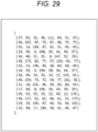
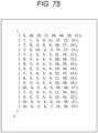
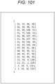
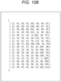
- Fig. 1 is a diagram for describing a first generation method of a predicted image of the MIP.
- the first generation method is a method for generating a predicted image of MIP proposed in Reference REF 3 (JVET-N1001-v7).
- predMip [x] [y] (pixel values) of (some) pixels of the predicted image of the current prediction block which is the prediction block to be encoded/decoded) is generated.
- predMip x y ⁇ mWeight i y*incH*predC + x*incW * p i + vBias y * incH * predC + x * incW ⁇ sB + oW ⁇ sW
- predMip [x] [y] represents pixels (pixel values) in which a horizontal position of the predicted image is x and a vertical position thereof is y.
- the pixel of the predicted image is also referred to as a predicted pixel.
- a summation ⁇ represents a summation taken while changing variable i to an integer from 0 to 2 * boundarySize-1.
- the boundarySize is set corresponding to the block size of the current prediction block. Specifically, the boundarySize is set according to Table 8-7 of Reference REF 3 according to MipSizeld which is an identifier of the matrix size of the matrix (weight matrix mWeight [i] [j]) used for the operation (matrix operation) with the pixel of the current prediction block in the MIP.
- the MipSizeld is set to 0, 1, and 2, respectively, when the matrix size is 4 ⁇ 4, 8 ⁇ 8, and 16 ⁇ 16.
- mWeight [i] [j] represents components of a j-th row and an i-th column of the matrix used in the MIP, and is referred to as a weight matrix.
- the weight matrix mWeight [i] [j] is set according to the MipSizeld and the modeld.
- the number of values taken by arguments i and j of the weight matrix mWeight [i] [j] is equal to the number of pixels obtained by averaging in reference REF 5 and the number of pixels predMip [x] [y] of the predicted image, respectively.
- a sum-of-product arithmetic ⁇ mWeight [i] [y * incH * predC + x * incW] * p [i] performed using the weight matrix mWeight [i] [j] is the matrix operation performed on (pixels of) the current prediction block in the MIP. That is, the sum-of-product ⁇ mWeight [i] [y * incH * predC + x * incW] * p [i] is a matrix operation to obtain a product of a matrix whose component is the weight matrix mWeight [i] [j] and a vector whose component is a pixel p[i] of the current prediction block.
- the modeld is set to any value from 0 to 17 according to Equation (8-64) of reference REF 3 according to the intra prediction mode predModeIntra.
- incH and incW are set according to Equations (8-67) and (8-68) of Reference REF 3, respectively, according to PredC.
- the PredC is set according to Table 8-7 of reference REF 3 according to the MipSizeld.
- a ⁇ B and A >> B indicate that A is shifted left and right by a B bit, respectively.
- sW is a shift amount that shifts (( ⁇ mWeight [i] [y * incH * predC + x * incW] * p [i]) + (vBias [y * incH * predC + x * incW] ⁇ sB ) + oW).
- the shift amount sW is set to one of 8 and 9 according to the MipSizeld and the modeld as illustrated in Fig. 1 .
- the first generation method when the first generation method is implemented by hardware, a selector for switching the shift amount sW is required, which increases the circuit scale. Further, when the first generation method is implemented by software, it is necessary to reference the table specified as Table 8-8 in Reference REF 3, and the processing speed is reduced by that amount.
- the MIP is performed using a shift amount set to a fixed value. That is, for example, the operation of Equation (1) is changed according to the shift amount sW set to the fixed value, and the predicted image of the MIP is generated according to the changed operation.
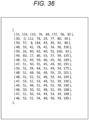
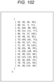
- Fig. 2 is a diagram for describing a second generation method of a predicted image of MIP.
- M represents the MipSizeld
- m represents the modeld
- the shift amount sW is fixed regardless of the modeld and the combination of the MipSizeld and the modeld, so the processing of the MIP can be simplified.
- the selector for switching the shift amount sW is not required, which can suppress the increases in the circuit scale.
- the second generation method is implemented by software, it is not necessary to reference the table specified as Table 8-8 in Reference REF 3, and it is possible to suppress the decrease in the processing speed compared to the case of referencing the table.
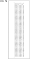
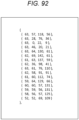
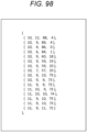
- the j + 1th value from the top represent the weight matrix mWeight [i] [j].
- the shift amount sW set to the fixed value is used to perform the operation, and can be changed as appropriate within the range in which the technical effect is appropriately exhibited. Further, since the range in which the technical effect is exhibited changes depending on the approximate level to be set, it can be appropriately changed as long as it falls within those ranges. For example, it can be changed within the range of ⁇ 1 and can be changed within the range of ⁇ 3. Furthermore, it is possible not only to change all values uniformly, but also to change only some values. It is also possible to set the range of values to be changed individually with respect to the existing values.
- the range (degree) at which the technical effect is exhibited is changed depending on how much the degree to which the fixed prediction pixel predMip [x] [y] approximates the standard prediction pixel predMip [x] [y] (hereinafter, also referred to as the approximation level) is set.
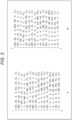
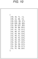
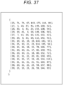
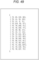
- Fig. 6 is a diagram for describing a third generation method of a predicted image of MIP.
- predMip x y ⁇ mWeight i y * incH * predC + x * incW * p i + oW ⁇ sW + dcVal
- Equation (2) a summation ⁇ represents a summation taken while changing variable i to an integer from 0 to inSize-1.
- the inSize is set to 2 * boundarySize-1 or 2 * boundarySize.
- the variable oW corresponds to the bias vector vBias [j] in Equation (1).
- Equation (3) a summation ⁇ represents a summation taken while changing variable i to an integer from 0 to inSize-1.
- variable fO is set according to the MipSizeld and the modeld. Since the variable oW corresponding to the bias vector vBias [j] is calculated according to Equation (3) using the variable fO, similar to the variable oW, the variable fO can also correspond to the bias vector vBias [j].
- sW is the shift amount that shifts (( ⁇ mWeight [i] [y * incH * predC + x * incW] * p [i]) + oW) .
- the shift amount sW is set to 6, 7, or 8 according to the MipSizeld and the modeld as illustrated in Fig. 6 .
- the shift amount sW of Equation (2) for generating the predicted image of the MIP proposed in Reference A is set to the fixed value.
- the minimum value of 6, the maximum value of 8, or the median value of 7 is used, or other values can be adopted.
- the minimum value of 6 is adopted as the fixed value set for the shift amount sW.
- the shift amount sW is fixed to 6 for each combination of the MipSizeld and the modeld.
- variable fO before setting the shift amount sW to the fixed value here, the variable fO specified in Reference A is also referred to as the standard variable fO.
- the MIP is performed using the shift amount sW set to the fixed value. That is, the operation of Equation (2) is changed according to the shift amount sW set to the fixed value, and the predicted image of the MIP is generated according to the changed operation.
- the shift amount sW is fixed regardless of the modeld and the combination of the MipSizeld and the modeld, so the processing of the MIP can be simplified. As a result, it is not necessary to specify the table specified as Table 8-8 in Reference A in the standard, and the standard can be simplified.
- the selector for switching the shift amount sW is not required, which can suppress the increases in the circuit scale.
- the third generation method is implemented by software, it is not necessary to reference the table specified as Table 8-8 in Reference A, and it is possible to suppress the decrease in the processing speed compared to the case of referencing the table.
- Fig. 7 is a diagram for describing a fourth generation method of a predicted image of MIP.
- the shift amount sW of the operation for generating the predicted image of the MIP proposed in Reference A is set to the fixed value according to the matrix size of the weight matrix mWeight [i] [j] used in the MIP.
- the MipSizeld is an identifier of the matrix size of the weight matrix mWeight [i] [j]
- setting the shift amount sW to the fixed value according to the matrix size is equivalent to setting the shift amount sW to the fixed value according to the MipSizeld, for example, setting the shift amount sW to the fixed value for each MipSizeld, or the like.
- the operation to generate the predicted image of the MIP is changed according to the shift amount sW set to the fixed value for each MipSizeld, and the predicted image of the MIP is generated according to the changed operation.
- the fixed value for each MipSizeld set in the shift amount sW for example, the minimum value or the maximum value of the shift amount sW for each MipSizeld described in Table 8-8 of Reference A or other values can be adopted.
- Equation (2) is changed according to the shift amount sW set to the fixed value for each MipSizeld, and the predicted image of the MIP is generated according to the changed operation.
- the MIP is performed using the shift amount set to the fixed value for each MipSizeld. That is, the operation of Equation (2) is changed according to the shift amount sW set to the fixed value for each MiPSizeld, and the predicted image of the MIP is generated according to the changed operation.
- the shift amount sW is fixed regardless of the modeld, so the MIP processing can be simplified, and the table for each modeld specified as Table 8-8 in Reference A is not defined in the standard, and the standard can be simplified.
- the selector for switching the shift amount sW is not required, which can suppress the increases in the circuit scale.
- the fourth generation method is implemented by software, it is not necessary to reference the table specified as Table 8-8 in Reference A, and it is possible to suppress the decrease in the processing speed compared to the case of referencing the table.
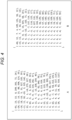
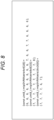
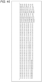
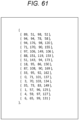
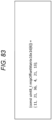
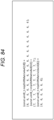
- Fig. 8 is a diagram illustrating the shift amount sW described in Reference A.
- the M + 1th value from the top represent the shift amount sW of (M, m). The same applies to the diagram of the shift amount sW described later.
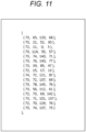
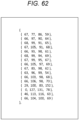
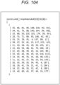
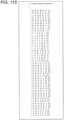
- Fig. 46 is a diagram illustrating the shift amount sW used in the third generation method.
- the shift amount sW is set to the fixed value, for example, 6.
- the standard weight matrix mWeight [i] [j] the fixed weight matrix mWeight [i] [j] obtained by changing the standard variable fO, and the fixed variable fO are used so that the fixed predicted pixel predMip [x] [y] obtained after setting the shift amount sW to the fixed value of 6 is a value approximating the standard predicted pixel predMip [x] [y].
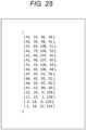
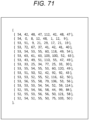
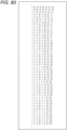
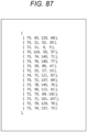
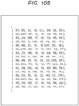
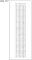
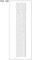
- Fig. 84 is a diagram illustrating the shift amount sW used in the fourth generation method.
- the standard weight matrix mWeight [i] [j] the fixed weight matrix mWeight [i] [j] obtained by changing the standard variable fO, and the fixed variable fO are used so that the fixed predicted pixel predMip [x] [y] obtained after setting the shift amount sW to the fixed value is a value approximating the standard predicted pixel predMip [x] [y].
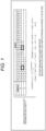
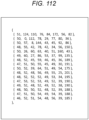
- Fig. 122 is a block diagram illustrating a configuration example of an embodiment of an image processing system to which the present technology is applied.
- the image processing system 10 has an image processing device as an encoder 11 and an image processing device as a decoder 51.
- the encoder 11 encodes the original image to be encoded supplied to the encoder 11 and outputs an encoded bitstream obtained by the encoding.
- the encoded bitstream is supplied to the decoder 51 via a recording medium or a transmission medium (not illustrated).
- the decoder 51 decodes the encoded bitstream supplied thereto and outputs the decoded image obtained by the decoding.
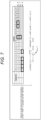
- Fig. 123 is a block diagram illustrating a configuration example of the encoder 11 of Fig. 122 .
- the encoder 11 includes an A/D conversion unit 21, a rearrangement buffer 22, a calculation unit 23, an orthogonal transform unit 24, a quantization unit 25, a reversible encoding unit 26, and an accumulation buffer 27. Further, the encoder 11 includes an inverse quantization unit 28, an inverse orthogonal transform unit 29, a calculation unit 30, a frame memory 32, a selection unit 33, an intra prediction unit 34, a motion prediction/compensation unit 35, a prediction image selection unit 36, and a rate control unit 37. Further, the encoder 11 has a deblocking filter 31a, an adaptive offset filter 41, and an adaptive loop filter (ALF) 42.
- ALF adaptive loop filter
- the A/D conversion unit 21 A/D-converts the original image (encoding target) of the analog signal into an original image of a digital signal, and supplies and stores the A/D converted original image to and in the rearrangement buffer 22. Note that when the original image of the digital signal is supplied to the encoder 11, the encoder 11 can be configured without providing the A/D conversion unit 21.
- the rearrangement buffer 22 rearranges the frame of the original image from the display order to the encoding (decoding) order according to a group of picture (GOP), and supplies the frame to the calculation unit 23, the intra prediction unit 34, and the motion prediction/compensation unit 35.
- GOP group of picture
- the calculation unit 23 subtracts the predicted image supplied from the intra prediction unit 34 or the motion prediction/compensation unit 35 via the prediction image selection unit 36 from the original image from the rearrangement buffer 22, and supplies the residual (predicted residual) obtained by the subtraction to the orthogonal transform unit 24.
- the orthogonal transform unit 24 performs an orthogonal transform such as a discrete cosine transform or a Karhunen-Loève transform on the residual supplied from the calculation unit 23, and supplies the orthogonal transform coefficient obtained by the orthogonal transform to the quantization unit 25.
- an orthogonal transform such as a discrete cosine transform or a Karhunen-Loève transform
- the quantization unit 25 quantizes the orthogonal transform coefficient supplied from the orthogonal transform unit 24.
- the quantization unit 25 sets a quantization parameter based on a target value of a code amount (code amount target value) supplied from the rate control unit 37, and performs the quantization of the orthogonal transform coefficient.
- the quantization unit 25 supplies encoded data, which is the quantized orthogonal transform coefficient, to the reversible encoding unit 26.
- the reversible encoding unit 26 encodes the quantized orthogonal transform coefficient as the encoded data from the quantization unit 25 by a predetermined reversible encoding method.
- the reversible encoding unit 26 acquires encoding information required for decoding by the decoding device 170 from each block among encoding information related to the predictive encoding in the encoder 11.
- the encoding information for example, there are a prediction mode of intra prediction or inter prediction, motion information such as motion vector, a code amount target value, a quantization parameter, picture types (I, P, B), filter parameters such as deblocking filter 31a and the adaptive offset filter 41, and the like.
- the prediction mode can be obtained from the intra prediction unit 34 or the motion prediction/compensation unit 35.
- the motion information can be acquired from the motion prediction/compensation unit 35.
- the filter parameters of the deblocking filter 31a and the adaptive offset filter 41 can be acquired from the deblocking filter 31a and the adaptive offset filter 41, respectively.
- the reversible encoding unit 26 encodes the coding information by, for example, variable length coding or arithmetic coding such as context-adaptive variable length coding (CAVLC) or context-adaptive binary arithmetic coding (CABAC), or other reversible coding methods, generates the encoded bitstream including (multiplexed) the encoded information after encoding, the encoded data from the quantization unit 25 and supplied the generated encoded bitstream to the accumulation buffer 27.
- variable length coding or arithmetic coding such as context-adaptive variable length coding (CAVLC) or context-adaptive binary arithmetic coding (CABAC), or other reversible coding methods
- the above calculation unit 23 or the reversible encoding unit 26 constitutes an encoding unit that encodes an image, and the processing (process) performed by the encoding unit is the encoding process.
- the accumulation buffer 27 temporarily accumulates the encoded bitstream supplied from the reversible encoding unit 26.
- the encoded bitstream stored in the accumulation buffer 27 is read and transmitted at a predetermined timing.
- the encoded data which is the orthogonal transform coefficient quantized in the quantization unit 25, is not only supplied to the reversible encoding unit 26, but also to the inverse quantization unit 28.
- the inverse quantization unit 28 inversely quantizes the quantized orthogonal transform coefficient by a method corresponding to the quantization by the quantization unit 25, and supplies the orthogonal transform coefficient obtained by the inverse quantization is transmitted to the inverse orthogonal transform unit 29.
- the inverse orthogonal transform unit 29 inversely orthogonal transforms the orthogonal transform coefficient supplied from the inverse quantization unit 28 by a method corresponding to the orthogonal transform processing by the orthogonal transform unit 24, and supplies the residuals obtained as a result of the inverse orthogonal transform to the calculation unit 30.
- the calculation unit 30 adds the predicted image supplied from the intra prediction unit 34 or the motion prediction/compensation unit 35 via the prediction image selection unit 36 to the residual supplied from the inverse orthogonal transform unit 29, thereby obtaining and output (a part of) the decoded image from which the original image is decoded.
- the decoded image output by the calculation unit 30 is supplied to the deblocking filter 31a or the frame memory 32.
- the frame memory 32 temporarily stores the decoded image supplied from the calculation unit 30, and the decoded image (filter image) supplied from the ALF 42 and to which the deblocking filter 31a, the adaptive offset filter 41, and the ALF 42 are applied.
- the decoded image stored in the frame memory 32 is supplied to the selection unit 33 as the reference image used for generating the predicted image at a required timing.
- the selection unit 33 selects the supply destination of the reference image supplied from the frame memory 32.
- the selection unit 33 supplies the reference image supplied from the frame memory 32 to the intra prediction unit 34.
- the selection unit 33 supplies the reference image supplied from the frame memory 32 to the motion prediction/compensation unit 35.
- the intra prediction unit 34 performs the intra prediction (in-screen prediction) using the original image supplied from the rearrangement buffer 22 and the reference image supplied from the frame memory 32 via the selection unit 33.
- the intra prediction unit 34 selects the prediction mode of the optimum intra prediction based on a predetermined cost function, and supplies the predicted image generated from the reference image in the prediction mode of the optimum intra prediction to the prediction image selection unit 36. Further, the intra prediction unit 34 appropriately supplies the prediction mode of the intra prediction selected based on the cost function to the reversible encoding unit 26 and the like.
- the motion prediction/compensation unit 35 performs the motion prediction using the original image supplied from the rearrangement buffer 22 and the reference image supplied from the frame memory 32 via the selection unit 33. Further, the motion prediction/compensation unit 35 performs motion compensation according to the motion vector detected by the motion prediction and generates the predicted image.
- the motion prediction/compensation unit 35 performs inter prediction in a prediction mode of a plurality of inter predictions prepared in advance, and generates the predicted image from the reference image.
- the motion prediction/compensation unit 35 selects the prediction mode of the optimum inter prediction from the prediction mode of the plurality of inter predictions based on a predetermined cost function. Furthermore, the motion prediction/compensation unit 35 supplies the predicted image generated in the prediction mode of the optimum inter prediction to the prediction image selection unit 36.
- the motion prediction/compensation unit 35 supplies the prediction mode of the optimum inter prediction selected based on the cost function or motion information such as a motion vector required to decode the encoded data encoded in the prediction mode of the inter prediction to the reversible encoding unit 26.
- the prediction image selection unit 36 selects a supply source of the predicted image to be supplied to the calculation unit 23 and the calculation unit 30 from the intra prediction unit 34 and the motion prediction/compensation unit 35, and selects the predicted image supplied from the selected supply source to the calculation unit 23 and the calculation unit 30.
- the rate control unit 37 controls the rate of the quantization operation of the quantization unit 25 based on the code amount of the encoded bitstream accumulated in the accumulation buffer 27 so that overflow or underflow does not occur. That is, the rate control unit 37 sets the target code amount of the encoded bitstream and supplies the set target code amount to the quantization unit 25 so that the overflow and underflow of the accumulation buffer 27 does not occur.
- the deblocking filter 31a applies the deblocking filter to the decoded image from the calculation unit 30 as necessary, and supplies the decoded image (filtered image) to which the deblocking filter is applied, or the decoded image to which the deblocking filter is not applied to the adaptive offset filter 41.
- the adaptive offset filter 41 applies the adaptive offset filter to the decoded image from the deblocking filter 31a as necessary, and supplies the decoded image (filter image) to which the adaptive offset filter is applied or the decoded image to which the adaptive offset filter is not applied is applied to the ALF 42.
- the ALF 42 applies the ALF to the decoded image from the adaptive offset filter 41 as necessary, and supplies the decoded image to which the ALF is applied or the decoded image to which ALF is not applied to the frame memory 32.
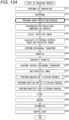
- Fig. 124 is a flowchart illustrating an example of the encoding processing of the encoder 11 of Fig. 123 .
- each step of encoding processing illustrated in Fig. 124 is an order for convenience of explanation, and each step of actual encoding processing is performed in a necessary order in parallel as appropriate. The same also applies to the processes described later.
- step S11 in the encoder 11, the A/D conversion unit 21 A/D-converts an original image and supplies the A/D-converted original image to the rearrangement buffer 22, and the process proceeds to step S12.
- step S12 the rearrangement buffer 22 stores the original images from the A/D conversion unit 21, rearranges the original images in the encoding order, and outputs the rearranged original images, and the process proceeds to step S13.
- step S13 the intra prediction unit 34 performs the intra prediction (intra prediction process), and the process proceeds to step S14.
- the motion prediction/compensation unit 35 performs inter prediction for motion prediction or motion compensation, and the process proceeds to step S15.
- the cost functions of various prediction modes are calculated and the predicted image is generated.
- step S15 the prediction image selection unit 36 determines the optimum prediction mode based on each cost function obtained by the intra prediction unit 34 and the motion prediction/compensation unit 35. Then, the prediction image selection unit 36 selects and outputs the predicted image of the optimum prediction mode from the predicted image generated by the intra prediction unit 34 and the predicted image generated by the motion prediction/compensation unit 35, and the process proceeds from step S15 to step S16.
- step S16 the calculation unit 23 calculates the residual between the target image to be encoded, which is the original image output by the rearrangement buffer 22, and the predicted image output by the prediction image selection unit 36, and supplies the calculated residual to the orthogonal transform unit 24, and the process proceeds to step S17.
- step S17 the orthogonal transform unit 24 orthogonal transforms the residual from the calculation unit 23 and supplies the resulting orthogonal transform coefficient to the quantization unit 25, and the process proceeds to step S18.
- step S18 the quantization unit 25 quantizes the orthogonal transform coefficient from the orthogonal transform unit 24 and supplies the quantization coefficient obtained by the quantization to the reversible encoding unit 26 and the inverse quantization unit 28, and the process proceeds to step S19.
- step S19 the inverse quantization unit 28 inversely quantizes the quantization coefficient from the quantization unit 25 and supplies the resulting orthogonal transform coefficient to the inverse orthogonal transform unit 29, and the process proceeds to step S20.
- step S20 the inverse orthogonal transform unit 29 inversely orthogonal transforms the orthogonal transform coefficient from the inverse quantization unit 28 and supplies the resulting residual to the calculation unit 30, and the process proceeds to step S21.
- step S21 the calculation unit 30 adds the residual from the inverse orthogonal transform unit 29 and the predicted image output by the prediction image selection unit 36, and generates the decoded image corresponding to the original image that becomes the target of the calculation of the residuals by the calculation unit 23.
- the calculation unit 30 supplies the decoded image to the deblocking filter 31a, and the process proceeds from step S21 to step S22.
- step S22 the deblocking filter 31a applies the deblocking filter to the decoded image from the calculation unit 30 and supplies the resulting filtered image to the adaptive offset filter 41, and the process proceeds to step S23.
- step S23 the adaptive offset filter 41 applies the adaptive offset filter to the filter image from the deblocking filter 31a and supplies the resulting filter image to ALF42, and the process proceeds to step S24.
- step S24 the ALF42 applies ALF to the filter image from the adaptive offset filter 41 and supplies the resulting filter image to the frame memory 32, and the process proceeds to step S25.
- step S25 the frame memory 32 stores the filter image supplied from the ALF42, and the process proceeds to step S26.
- the filtered image stored in the frame memory 32 is used as a reference image from which the predicted image is generated in steps S13 or S14.
- the reversible encoding unit 26 encodes the encoded data, which is the quantization coefficient from the quantization unit 25, and generates the encoded bitstream including the encoded data. Furthermore, the reversible encoding unit 26 encodes the encoding information, such as the quantization parameter used for the quantization in the quantization unit 25, the prediction mode obtained by the intra prediction in the intra prediction unit 34, the prediction mode or motion information obtained by the inter prediction in the motion prediction/compensation unit 35, or the filter parameters of the deblocking filter 31a and the adaptive offset filter 41, as necessary, and includes the encoded information in the encoded bitstream.
- the quantization parameter used for the quantization in the quantization unit 25 the prediction mode obtained by the intra prediction in the intra prediction unit 34, the prediction mode or motion information obtained by the inter prediction in the motion prediction/compensation unit 35, or the filter parameters of the deblocking filter 31a and the adaptive offset filter 41, as necessary, and includes the encoded information in the encoded bitstream.
- the reversible encoding unit 26 supplies the encoded bitstream to the accumulation buffer 27, and the process proceeds from step S26 to step S27.
- step S27 the accumulation buffer 27 accumulates the encoded bitstream from the reversible encoding unit 26, and the process proceeds to step S28.
- the encoded bitstream accumulated in the accumulation buffer 27 is appropriately read and transmitted.
- step S28 the rate control unit 37 controls the quantization operation of the quantization unit 25 based on the code amount (generated code amount) of the encoded bitstream accumulated in the accumulation buffer 27 so that overflow or underflow does not occur, and the encoding processing ends.
- Fig. 125 is a block diagram illustrating a configuration example of the decoder 51 of Fig. 122 .
- the decoder 51 has an accumulation buffer 61, a reversible decoding unit 62, an inverse quantization unit 63, an inverse orthogonal transform unit 64, a calculation unit 65, a rearrangement buffer 67, and a D/A conversion unit 68. Further, the decoder 51 has a frame memory 69, a selection unit 70, an intra prediction unit 71, a motion prediction/compensation unit 72, and a selection unit 73. Further, the decoder 51 has a deblocking filter 31b, an adaptive offset filter 81, and an ALF 82.
- the accumulation buffer 61 temporarily accumulates the encoded bitstream transmitted from the encoder 11 and supplies the encoded bitstream to the reversible decoding unit 62 at a predetermined timing.
- the reversible decoding unit 62 receives the encoded bitstream from the accumulation buffer 61 and decodes the received encoded bitstream by a method corresponding to the encoding method of the reversible encoding unit 26 in Fig. 123
- the reversible decoding unit 62 supplies the quantization coefficient as the encoded data included in the decoding result of the encoded bitstream to the inverse quantization unit 63.
- the reversible decoding unit 62 has a function of performing parsing.
- the reversible decoding unit 62 parses the necessary encoding information included in the decoding result of the encoded bitstream and supplies the encoding information to the intra prediction unit 71, the motion prediction/compensation unit 72, the deblocking filter 31b, the adaptive offset filter 81, and other necessary blocks.
- the inverse quantization unit 63 inversely quantizes the quantization coefficient as the encoded data from the reversible decoding unit 62 by the method corresponding to the quantization method of the quantization unit 25 in Fig. 123 , and supplies the orthogonal transform coefficient obtained by the inverse quantization to the inverse orthogonal transform unit 64.
- the inverse orthogonal transform unit 64 inversely orthogonal transforms the orthogonal transform coefficient supplied from the inverse quantization unit 63 by the method corresponding to the orthogonal transform method of the orthogonal transform unit 24 in Fig. 123 , and supplies the resulting residual to the calculation unit 65.
- the predicted image is supplied from the intra prediction unit 71 or the motion prediction/compensation unit 72 via the selection unit 73.
- the calculation unit 65 adds the residual from the inverse orthogonal transform unit 64 and the predicted image from the selection unit 73, generates the decoded image, and supplies the generated decoded image to the deblocking filter 31b.
- the above reversible decoding unit 62 to calculation unit 65 constitute a decoding unit that decodes an image, and the processing (process) performed by the decoding unit is the decoding process.
- the rearrangement buffer 67 temporarily stores the decoded image supplied from the ALF 82, rearranges the arrangement of the frames (pictures) of the decoded image from the encoding (decoding) order to the display order, and supplies the rearranged frame to the D/A conversion unit 68.
- the D/A conversion unit 68 D/A-converts the decoded image supplied from the rearrangement buffer 67 and outputs the D/A-converted decoded image to a display (not illustrated) for display. Note that when the device connected to the decoder 51 accepts an image of a digital signal, the decoder 51 can be configured without providing the D/A conversion unit 68.
- the frame memory 69 temporarily stores the decoded image supplied from the ALF 82. Furthermore, the frame memory 69 supplies the decoded image to the selection unit 70 as a reference image for generating the predicted image at a predetermined timing or based on an external request such as the intra prediction unit 71 or the motion prediction/compensation unit 72.
- the selection unit 70 selects the supply destination of the reference image supplied from the frame memory 69.
- the selection unit 70 supplies the reference image supplied from the frame memory 69 to the intra prediction unit 71.
- the selection unit 70 supplies the reference image supplied from the frame memory 69 to the motion prediction/compensation unit 72.
- the intra prediction unit 71 performs the intra prediction similar to the intra prediction unit 34 of Fig. 123 using the reference image supplied from the frame memory 69 via the selection unit 70, according to the prediction mode included in the encoded information supplied from the reversible decoding unit 62. Then, the intra prediction unit 71 supplies the predicted image obtained by the intra prediction to the selection unit 73.
- the motion prediction/compensation unit 72 performs the inter prediction using the reference image supplied from the frame memory 69 via the selection unit 70, according to the prediction mode included in the encoding information supplied from the reversible decoding unit 62.
- the inter prediction is performed by using the motion information and the like included in the encoding information supplied from the reversible decoding unit 62 as necessary.
- the motion prediction/compensation unit 72 supplies the predicted image obtained by the inter prediction to the selection unit 73.
- the selection unit 73 selects the predicted image supplied from the intra prediction unit 71 or the predicted image supplied from the motion prediction/compensation unit 72, and supplies the predicted image to the calculation unit 65.
- the deblocking filter 31b applies the deblocking filter to the decoded image from the calculation unit 65 according to the filter parameter included in the encoding information supplied from the reversible decoding unit 62.
- the deblocking filter 31b supplies the decoded image (filtered image) to which the deblocking filter is applied or the decoded image to which the deblocking filter is not applied to the adaptive offset filter 81.
- the adaptive offset filter 81 applies the adaptive offset filter to the decoded image from the deblocking filter 31b as necessary according to the filter parameter included in the encoding information supplied from the reversible decoding unit 62.
- the adaptive offset filter 81 supplies the decoded image (filtered image) to which the adaptive offset filter is applied or the decoded image to which the adaptive offset filter is not applied to the ALF 82.
- the ALF 82 applies the ALF to the decoded image from the adaptive offset filter 81 as necessary, and supplies the decoded image to which the ALF is applied or the decoded image to which ALF is not applied to the rearrangement buffer 67 and the frame memory 69.
- Fig. 126 is a flowchart illustrating an example of the decoding processing of the decoder 51 of Fig. 125 .
- step S51 in decoding processing, the accumulation buffer 61 temporarily stores the encoded bitstream transmitted from the encoder 11 and supplies the stored encoded bitstream to the reversible decoding unit 62 as appropriate, and the process proceeds to step S52.
- step S52 the reversible decoding unit 62 receives and decodes the encoded bitstream supplied from the accumulation buffer 61, and supplies the quantization coefficient as the encoded data included in the decoding result of the encoded bitstream to the inverse quantization unit 63.
- the reversible decoding unit 62 parses the encoding information included in the decoding result of the encoded bitstream. Then, the reversible decoding unit 62 supplies the necessary encoding information to the intra prediction unit 71, the motion prediction/compensation unit 72, the deblocking filter 31b, the adaptive offset filter 81, and other necessary blocks.
- step S52 the intra prediction unit 71 or the motion prediction/compensation unit 72 performs the intra prediction or the inter prediction (intra prediction process or inter prediction process) generating the predicted image, according to the reference image supplied from the frame memory 69 via the selection unit 70 and the encoding information supplied from the reversible decoding unit 62.
- the intra prediction unit 71 or the motion prediction/compensation unit 72 supplies the predicted image obtained by the intra prediction or the inter prediction to the selection unit 73, and the process proceeds from step S53 to step S54.
- step S54 the selection unit 73 selects the predicted image supplied from the intra prediction unit 71 or the motion prediction/compensation unit 72 and supplies the selected predicted image to the calculation unit 65, and the process proceeds to step S55.
- step S55 the inverse quantization unit 63 inversely quantizes the quantization coefficient from the reversible decoding unit 62 and supplies the resulting orthogonal transform coefficient to the inverse orthogonal transform unit 64, and the process proceeds to step S56.
- step S56 the inverse orthogonal transform unit 64 inversely orthogonal transforms the orthogonal transform coefficient from the inverse quantization unit 63 and supplies the resulting residual to the calculation unit 65, and the process proceeds to step S57.
- step S57 the calculation unit 65 generates the decoded image by adding the residual from the inverse orthogonal transform unit 64 and the predicted image from the selection unit 73. Then, the calculation unit 65 supplies the decoded image to the deblocking filter 31b, and the process proceeds from step S57 to step S58.
- step S58 the deblocking filter 31b applies the deblocking filter to the decoded image from the calculation unit 65 according to the filter parameter included in the encoding information supplied from the reversible decoding unit 62.
- the deblocking filter 31b supplies the filtered image obtained as a result of applying the deblocking filter to the adaptive offset filter 81, and the process proceeds from step S58 to step S59.
- step S59 the adaptive offset filter 81 applies the adaptive offset filter to the filtered image from the deblocking filter 31b according to the filter parameter included in the encoding information supplied from the reversible decoding unit 62.
- the adaptive offset filter 81 supplies the filtered image obtained as a result of applying the adaptive offset filter to the ALF 82, and the process proceeds from step S59 to step S60.
- the ALF 82 applies ALF to the filter image from the adaptive offset filter 81 and supplies the resulting filter image to the rearrangement buffer 67 and the frame memory 69, and the process proceeds to step S61.
- step S61 the frame memory 69 temporally stores the filtered image supplied from the ALF 82, and the process proceeds to step S62.
- the filtered image (decoded image) stored in the frame memory 69 is used as the reference image from which the predicted image is generated by the intra prediction or the inter prediction in step S53.
- step S62 the rearrangement buffer 67 rearranges the filtered images supplied from ALF 82 in the display order and supplies the rearranged filtered images to the D/A conversion unit 68, and the process proceeds to step S63.
- step S63 the D/A conversion unit 68 D/A-converts the filtered image from the rearrangement buffer 67, and the process ends the decoding processing.
- the filter image (decoded image) after D/A conversion is output and displayed on a display (not illustrated).
- the intra prediction performed by the intra prediction unit 34 of Fig. 123 and the intra prediction unit 71 of Fig. 125 includes the MIP.
- the generation of the predicted image of the MIP is generated by any of the second to fourth generation methods.
- the present technology can be applied to any image coding/decoding method. That is, as long as it does not contradict the above-described present technology, the specifications of various processes related to image encoding/decoding such as conversion (inverse transformation), quantization (inverse quantization), encoding (decoding), and prediction are arbitrary, and therefore the present technique is not limited to the example. In addition, some of these processes may be omitted as long as they do not contradict the present technology described above.
- a "block” (not a block indicating a processing unit) used as a partial area or a processing unit of an image (picture) indicates an arbitrary partial area in the picture, and a size, a shape, and characteristics of the block are not limited.
- the "block” includes any partial area (processing unit) such as a transform block (TB), a transform unit (TU), a prediction block (PB), a prediction unit (PU), a smallest coding unit (SCU), a coding unit (CU), a largest coding unit (LCU), a coding tree block (CTB), a coding tree unit (CTU), a conversion block, a sub-block, a macroblock, a tile, or a slice, which are described in references REF 1 to REF 3 or the like.
- processing unit such as a transform block (TB), a transform unit (TU), a prediction block (PB), a prediction unit (PU), a smallest coding unit (SCU), a coding unit (CU), a largest coding unit (LCU), a coding tree block (CTB), a coding tree unit (CTU), a conversion block, a sub-block, a macroblock, a tile, or a slice, which are described in references REF 1 to REF 3 or
- a data unit in which various pieces of information described above is set and a data unit targeted by various types of processing are each arbitrary and are not limited to the above-described examples.
- these pieces of information or processing may be set for each transform unit (TU), transform block (TB), prediction unit (PU), prediction block (PB), coding unit (CU), largest coding unit (LCU), sub-block, block, tile, slice, picture, sequence, or component, or may target the data in those data units.
- this data unit can be set for each information or processing, and it is not necessary that the data unit of all the information or processing is unified.
- a storage location of these pieces of information is arbitrary, and these pieces of information may be stored in a header, a parameter set, or the like of the above-described data unit. Further, these pieces of information may be stored in a plurality of locations.
- control information related to the present technology described above may also be transmitted from the encoding side to the decoding side.
- control information for example, enabled_flag
- the control information indicating a target (or a target to which the present technology is not applied) to which the present technology is applied may be transmitted.
- the control information that specifies the block size (upper and lower limits, or both) to which the present technology is applied (or permitted or prohibited), frames, components, layers, or the like may be transmitted.
- the block size may be specified using identification data for identifying the size.
- the block size may be specified by a ratio or a difference with a size of a reference block (for example, LCU, SCU, or the like).
- a reference block for example, LCU, SCU, or the like.
- the specification of the block size also includes the specification of the range of the block size (for example, a specification or the like of a range of an allowable block size).
- the "identification data” is information for identifying a plurality of states, and includes “flags” and those of other names. Further, the “identification data” includes not only information used for identifying two states of true (1) or false (0), but also information capable of identifying three or more states. Therefore, the value that this "identification data” can take may be, for example, 2 values of 1/0, or 3 or more values. That is, the number of bits constituting the "identification data" is arbitrary, and may be 1 bit or a plurality of bits.
- the identification data is assumed to include not only the identification data in the bitstream but also difference information of the identification data which becomes a certain reference information in the bitstream, in the present specification, the "identification data" include not only the information but also the difference information which becomes the reference information.
- various types of information (metadata, or the like) on encoded data may be transmitted or recorded in any form as long as the information is associated with the encoded data.
- the term "associating" means, for example, to make other data available (linkable) when processing one data. That is, the data associated with each other may be combined as one data or may be individual data.
- the information associated with the encoded data (image) may be transmitted on a transmission path different from that encoded data (image).
- the information associated with the encoded data (image) may also be recorded on a recording medium (or another recording area of the same recording medium) different from the encoded data (image).
- this "association" may be a part of data, not the entire data.
- an image and information corresponding to the image may be associated with each other in arbitrary units such as a plurality of frames, one frame, or a part within a frame.
- the terms such as “synthesize”, “multiplex”, “add”, “integrate”, “include”, “store”, “push into”, “put in”, and “insert” mean combining a plurality of things into one, for example, combining encoded data and metadata into one data, and means one method of "associating" described above.
- the present technology can be implemented as any configuration that constitutes a device or a system, for example, a processor as system large scale integration (LSI) or the like, a module that uses a plurality of processors or the like, a unit that uses a plurality of modules or the like, and a set with other functions further added to the unit, or the like (that is, a part of the configuration of the device).
- LSI system large scale integration
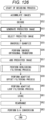
- Fig. 127 is a block diagram illustrating a configuration example of an embodiment of the computer on which the program for executing some or all of the above-described series of processes is installed.
- the program can be recorded in advance on a hard disk 905 or a ROM 903 as a recording medium built in the computer.
- the program can be stored (recorded) in a removable recording medium 911 driven by a drive 909.
- a removable recording medium 911 can be provided as so-called package software.
- examples of the removable recording medium 911 include a flexible disc, a compact disc read only memory (CD-ROM), a magneto optical (MO) disc, a digital versatile disc (DVD), a magnetic disc, a semiconductor memory, and the like.
- the program can be not only installed on the computer from the removable recording medium 911 as described above, but can also be downloaded to the computer via a communication network or a broadcasting network and installed on the built-in hard disk 905. That is, for example, the program can be transmitted wirelessly from a download site to a computer via an artificial satellite for digital satellite broadcasting, or can be transmitted to a computer by wire via a network such as a local area network (LAN) or the Internet.
- LAN local area network
- the computer has a built-in central processing unit (CPU) 902, and the input/output interface 910 is connected to the CPU 902 via the bus 901.
- CPU central processing unit
- the CPU 902 executes the program stored in the read only memory (ROM) 903 accordingly.
- the CPU 902 loads the program stored in the hard disk 905 into a random access memory (RAM) 904 and executes the loaded program.
- the CPU 902 performs processing according to the above-described flowchart or processing performed according to the configuration of the above-described block diagram. Then, the CPU 902 outputs the processing result from the output unit 906 from the communication unit 908, or transmits the processing result from the communication unit 908 via, for example, the input/output interface 910, as necessary, and furthermore records the processing result on the hard disk 905.
- the input unit 907 is constituted by a keyboard, a mouse, a microphone, and the like.
- the output unit 906 is constituted by a liquid crystal display (LCD), a speaker, or the like.
- the processing performed by the computer according to the program does not necessarily have to be performed in a time sequence according to the order described as the flowchart. That is, the processing performed by the computer according to the program also includes processing (for example, parallel processing or processing by an object) executed in parallel or individually.
- the program may be processed by one computer (processor) or may be distributed and processed by a plurality of computers. Furthermore, the program may be transmitted to a distant computer and executed.
- the system means a set of a plurality of components (devices, modules (parts), etc.), and it does not matter whether or not all the components are in the same housing. Therefore, any of a plurality of devices housed in separate housings and connected via a network and one device in which a plurality of modules are housed in one housing are systems.
- the present technology can be configured as cloud computing in which one function is shared by a plurality of devices via a network and processed jointly.
- each step described in the above-described flowchart can be not also executed by one device, but can also be shared and executed by a plurality of devices.
- one step includes a plurality of processes
- the plurality of processes included in the one step can be executed by one device or shared and executed by a plurality of devices.
Landscapes
- Engineering & Computer Science (AREA)
- Multimedia (AREA)
- Signal Processing (AREA)
- Compression Or Coding Systems Of Tv Signals (AREA)
Applications Claiming Priority (4)
| Application Number | Priority Date | Filing Date | Title |
|---|---|---|---|
| US201962863664P | 2019-06-19 | 2019-06-19 | |
| US201962866281P | 2019-06-25 | 2019-06-25 | |
| EP20827185.8A EP3989578B1 (de) | 2019-06-19 | 2020-06-08 | Bildverarbeitungsvorrichtung und bildverarbeitungsverfahren |
| PCT/JP2020/022485 WO2020255769A1 (ja) | 2019-06-19 | 2020-06-08 | 画像処理装置及び画像処理方法 |
Related Parent Applications (2)
| Application Number | Title | Priority Date | Filing Date |
|---|---|---|---|
| EP20827185.8A Division-Into EP3989578B1 (de) | 2019-06-19 | 2020-06-08 | Bildverarbeitungsvorrichtung und bildverarbeitungsverfahren |
| EP20827185.8A Division EP3989578B1 (de) | 2019-06-19 | 2020-06-08 | Bildverarbeitungsvorrichtung und bildverarbeitungsverfahren |
Publications (2)
| Publication Number | Publication Date |
|---|---|
| EP4274230A2 true EP4274230A2 (de) | 2023-11-08 |
| EP4274230A3 EP4274230A3 (de) | 2024-01-17 |
Family
ID=74037296
Family Applications (2)
| Application Number | Title | Priority Date | Filing Date |
|---|---|---|---|
| EP23190099.4A Pending EP4274230A3 (de) | 2019-06-19 | 2020-06-08 | Bildverarbeitungsvorrichtung und bildverarbeitungsverfahren |
| EP20827185.8A Active EP3989578B1 (de) | 2019-06-19 | 2020-06-08 | Bildverarbeitungsvorrichtung und bildverarbeitungsverfahren |
Family Applications After (1)
| Application Number | Title | Priority Date | Filing Date |
|---|---|---|---|
| EP20827185.8A Active EP3989578B1 (de) | 2019-06-19 | 2020-06-08 | Bildverarbeitungsvorrichtung und bildverarbeitungsverfahren |
Country Status (13)
| Country | Link |
|---|---|
| US (1) | US20220353546A1 (de) |
| EP (2) | EP4274230A3 (de) |
| JP (1) | JPWO2020255769A1 (de) |
| KR (1) | KR20220021471A (de) |
| CN (1) | CN114051733A (de) |
| DK (1) | DK3989578T3 (de) |
| ES (1) | ES2962996T3 (de) |
| FI (1) | FI3989578T3 (de) |
| HU (1) | HUE063717T2 (de) |
| LT (1) | LT3989578T (de) |
| PL (1) | PL3989578T3 (de) |
| SI (1) | SI3989578T1 (de) |
| WO (1) | WO2020255769A1 (de) |
Families Citing this family (2)
| Publication number | Priority date | Publication date | Assignee | Title |
|---|---|---|---|---|
| BR112021006724A2 (pt) * | 2019-06-25 | 2022-02-01 | Guangdong Oppo Mobile Telecommunications Corp Ltd | Método de conversão de figuração em código aplicado a um codificador, método de decodificação de figuração aplicado a um decodificador, decodificador, e mídia de armazenamento legível por computador |
| GB2588406B (en) * | 2019-10-22 | 2022-12-07 | British Broadcasting Corp | Video encoding and video decoding |
Family Cites Families (2)
| Publication number | Priority date | Publication date | Assignee | Title |
|---|---|---|---|---|
| KR102086145B1 (ko) * | 2010-12-13 | 2020-03-09 | 한국전자통신연구원 | 인트라 예측 방법 및 그 장치 |
| EP4054193A4 (de) * | 2019-12-20 | 2023-01-25 | Sony Group Corporation | Bildverarbeitungsvorrichtung und bildverarbeitungsverfahren |
-
2020
- 2020-06-08 FI FIEP20827185.8T patent/FI3989578T3/fi active
- 2020-06-08 JP JP2021527612A patent/JPWO2020255769A1/ja active Pending
- 2020-06-08 DK DK20827185.8T patent/DK3989578T3/da active
- 2020-06-08 ES ES20827185T patent/ES2962996T3/es active Active
- 2020-06-08 LT LTEPPCT/JP2020/022485T patent/LT3989578T/lt unknown
- 2020-06-08 SI SI202030295T patent/SI3989578T1/sl unknown
- 2020-06-08 EP EP23190099.4A patent/EP4274230A3/de active Pending
- 2020-06-08 EP EP20827185.8A patent/EP3989578B1/de active Active
- 2020-06-08 US US17/616,682 patent/US20220353546A1/en active Pending
- 2020-06-08 HU HUE20827185A patent/HUE063717T2/hu unknown
- 2020-06-08 CN CN202080042945.3A patent/CN114051733A/zh active Pending
- 2020-06-08 WO PCT/JP2020/022485 patent/WO2020255769A1/ja unknown
- 2020-06-08 PL PL20827185.8T patent/PL3989578T3/pl unknown
- 2020-06-08 KR KR1020217038773A patent/KR20220021471A/ko unknown
Non-Patent Citations (7)
| Title |
|---|
| "Advanced video coding for generic audiovisual services", RECOMMENDATION ITU-T H.264, April 2017 (2017-04-01) |
| "High efficiency video coding", RECOMMENDATION ITU-T H.265, February 2018 (2018-02-01) |
| BENJAMIN BROSSJIANLE CHENSHAN LIU, VERSATILE VIDEO CODING (DRAFT 5), JVET-N1001-V7, 29 May 2019 (2019-05-29) |
| JIANLE CHENYAN YESEUNG HWAN KIM, ALGORITHM DESCRIPTION FOR VERSATILE VIDEO CODING AND TEST MODEL 5 (VTM 5 |
| JVET-00084-VL: 8-BIT IMPLEMENTATION AND SIMPLIFICATION OF MIP, 18 June 2019 (2019-06-18) |
| JVET-M0043-V2: CE3: AFFINE LINEAR WEIGHTED INTRA PREDICTION, 9 January 2019 (2019-01-09) |
| JVET-N0217-V3: CE3: AFFINE LINEAR WEIGHTED INTRA PREDICTION (CE3-4.1, CE3-4.2, 17 January 2019 (2019-01-17) |
Also Published As
| Publication number | Publication date |
|---|---|
| HUE063717T2 (hu) | 2024-01-28 |
| EP3989578A1 (de) | 2022-04-27 |
| CN114051733A (zh) | 2022-02-15 |
| EP3989578A4 (de) | 2022-08-17 |
| WO2020255769A1 (ja) | 2020-12-24 |
| EP3989578B1 (de) | 2023-09-13 |
| JPWO2020255769A1 (de) | 2020-12-24 |
| PL3989578T3 (pl) | 2024-02-26 |
| DK3989578T3 (da) | 2023-10-30 |
| EP4274230A3 (de) | 2024-01-17 |
| KR20220021471A (ko) | 2022-02-22 |
| ES2962996T3 (es) | 2024-03-22 |
| LT3989578T (lt) | 2023-11-10 |
| SI3989578T1 (sl) | 2024-02-29 |
| US20220353546A1 (en) | 2022-11-03 |
| FI3989578T3 (fi) | 2023-11-02 |
Similar Documents
| Publication | Publication Date | Title |
|---|---|---|
| US11871007B2 (en) | Encoding device, decoding device, encoding method, and decoding method | |
| EP3506639B1 (de) | Decodierungsverfahren und decodierungsvorrichtung | |
| US10855982B2 (en) | Image processing apparatus and method | |
| US20140056357A1 (en) | Encoding device, decoding device, encoding method, and decoding method | |
| EP4274230A2 (de) | Bildverarbeitungsvorrichtung und bildverarbeitungsverfahren | |
| EP3975564A1 (de) | Bildverarbeitungsvorrichtung und bildverarbeitungsverfahren | |
| US20210006836A1 (en) | Image encoding apparatus, image encoding method, image decoding apparatus, and image decoding method | |
| EP4054193A1 (de) | Bildverarbeitungsvorrichtung und bildverarbeitungsverfahren | |
| JP7235031B2 (ja) | 画像処理装置および方法 | |
| WO2020184715A1 (ja) | 画像処理装置および画像処理方法 | |
| JP2024069447A (ja) | 画像処理装置及び画像処理方法 | |
| US20220166975A1 (en) | Image processing device and image processing method | |
| WO2022202157A1 (ja) | 画像処理装置および方法 | |
| JP6682594B2 (ja) | 符号化方法および復号方法 | |
| WO2020129636A1 (ja) | 画像符号化装置、画像符号化方法、画像復号装置、および画像復号方法 | |
| US20220086489A1 (en) | Image processing apparatus and method | |
| JP6132950B2 (ja) | 符号化方法、復号方法、符号化装置、及び復号装置 | |
| KR20220113693A (ko) | 화상 처리 장치 및 화상 처리 방법 | |
| KR20220053561A (ko) | 화상 처리 장치 및 화상 처리 방법 |
Legal Events
| Date | Code | Title | Description |
|---|---|---|---|
| PUAI | Public reference made under article 153(3) epc to a published international application that has entered the european phase |
Free format text: ORIGINAL CODE: 0009012 |
|
| STAA | Information on the status of an ep patent application or granted ep patent |
Free format text: STATUS: REQUEST FOR EXAMINATION WAS MADE |
|
| 17P | Request for examination filed |
Effective date: 20230821 |
|
| AC | Divisional application: reference to earlier application |
Ref document number: 3989578 Country of ref document: EP Kind code of ref document: P |
|
| AK | Designated contracting states |
Kind code of ref document: A2 Designated state(s): AL AT BE BG CH CY CZ DE DK EE ES FI FR GB GR HR HU IE IS IT LI LT LU LV MC MK MT NL NO PL PT RO RS SE SI SK SM TR |
|
| PUAL | Search report despatched |
Free format text: ORIGINAL CODE: 0009013 |
|
| AK | Designated contracting states |
Kind code of ref document: A3 Designated state(s): AL AT BE BG CH CY CZ DE DK EE ES FI FR GB GR HR HU IE IS IT LI LT LU LV MC MK MT NL NO PL PT RO RS SE SI SK SM TR |
|
| RIC1 | Information provided on ipc code assigned before grant |
Ipc: H04N 19/593 20140101AFI20231212BHEP |