EP4273984A1 - Deviation correction apparatus and winding machine - Google Patents
Deviation correction apparatus and winding machine Download PDFInfo
- Publication number
- EP4273984A1 EP4273984A1 EP23171853.7A EP23171853A EP4273984A1 EP 4273984 A1 EP4273984 A1 EP 4273984A1 EP 23171853 A EP23171853 A EP 23171853A EP 4273984 A1 EP4273984 A1 EP 4273984A1
- Authority
- EP
- European Patent Office
- Prior art keywords
- electrode plate
- coating layer
- deviation correction
- width
- detecting apparatus
- Prior art date
- Legal status (The legal status is an assumption and is not a legal conclusion. Google has not performed a legal analysis and makes no representation as to the accuracy of the status listed.)
- Pending
Links
Images


Classifications
-
- B—PERFORMING OPERATIONS; TRANSPORTING
- B65—CONVEYING; PACKING; STORING; HANDLING THIN OR FILAMENTARY MATERIAL
- B65H—HANDLING THIN OR FILAMENTARY MATERIAL, e.g. SHEETS, WEBS, CABLES
- B65H23/00—Registering, tensioning, smoothing or guiding webs
- B65H23/02—Registering, tensioning, smoothing or guiding webs transversely
- B65H23/0204—Sensing transverse register of web
-
- H—ELECTRICITY
- H01—ELECTRIC ELEMENTS
- H01M—PROCESSES OR MEANS, e.g. BATTERIES, FOR THE DIRECT CONVERSION OF CHEMICAL ENERGY INTO ELECTRICAL ENERGY
- H01M10/00—Secondary cells; Manufacture thereof
- H01M10/04—Construction or manufacture in general
- H01M10/0404—Machines for assembling batteries
- H01M10/0409—Machines for assembling batteries for cells with wound electrodes
-
- B—PERFORMING OPERATIONS; TRANSPORTING
- B65—CONVEYING; PACKING; STORING; HANDLING THIN OR FILAMENTARY MATERIAL
- B65H—HANDLING THIN OR FILAMENTARY MATERIAL, e.g. SHEETS, WEBS, CABLES
- B65H23/00—Registering, tensioning, smoothing or guiding webs
- B65H23/02—Registering, tensioning, smoothing or guiding webs transversely
- B65H23/032—Controlling transverse register of web
-
- G—PHYSICS
- G01—MEASURING; TESTING
- G01B—MEASURING LENGTH, THICKNESS OR SIMILAR LINEAR DIMENSIONS; MEASURING ANGLES; MEASURING AREAS; MEASURING IRREGULARITIES OF SURFACES OR CONTOURS
- G01B11/00—Measuring arrangements characterised by the use of optical techniques
- G01B11/02—Measuring arrangements characterised by the use of optical techniques for measuring length, width or thickness
- G01B11/028—Measuring arrangements characterised by the use of optical techniques for measuring length, width or thickness by measuring lateral position of a boundary of the object
-
- G—PHYSICS
- G01—MEASURING; TESTING
- G01B—MEASURING LENGTH, THICKNESS OR SIMILAR LINEAR DIMENSIONS; MEASURING ANGLES; MEASURING AREAS; MEASURING IRREGULARITIES OF SURFACES OR CONTOURS
- G01B11/00—Measuring arrangements characterised by the use of optical techniques
- G01B11/02—Measuring arrangements characterised by the use of optical techniques for measuring length, width or thickness
- G01B11/06—Measuring arrangements characterised by the use of optical techniques for measuring length, width or thickness for measuring thickness ; e.g. of sheet material
- G01B11/0616—Measuring arrangements characterised by the use of optical techniques for measuring length, width or thickness for measuring thickness ; e.g. of sheet material of coating
-
- G—PHYSICS
- G01—MEASURING; TESTING
- G01N—INVESTIGATING OR ANALYSING MATERIALS BY DETERMINING THEIR CHEMICAL OR PHYSICAL PROPERTIES
- G01N21/00—Investigating or analysing materials by the use of optical means, i.e. using sub-millimetre waves, infrared, visible or ultraviolet light
- G01N21/84—Systems specially adapted for particular applications
- G01N21/88—Investigating the presence of flaws or contamination
- G01N21/89—Investigating the presence of flaws or contamination in moving material, e.g. running paper or textiles
- G01N21/8901—Optical details; Scanning details
-
- G—PHYSICS
- G01—MEASURING; TESTING
- G01N—INVESTIGATING OR ANALYSING MATERIALS BY DETERMINING THEIR CHEMICAL OR PHYSICAL PROPERTIES
- G01N21/00—Investigating or analysing materials by the use of optical means, i.e. using sub-millimetre waves, infrared, visible or ultraviolet light
- G01N21/84—Systems specially adapted for particular applications
- G01N21/88—Investigating the presence of flaws or contamination
- G01N21/89—Investigating the presence of flaws or contamination in moving material, e.g. running paper or textiles
- G01N21/892—Investigating the presence of flaws or contamination in moving material, e.g. running paper or textiles characterised by the flaw, defect or object feature examined
-
- H—ELECTRICITY
- H01—ELECTRIC ELEMENTS
- H01M—PROCESSES OR MEANS, e.g. BATTERIES, FOR THE DIRECT CONVERSION OF CHEMICAL ENERGY INTO ELECTRICAL ENERGY
- H01M10/00—Secondary cells; Manufacture thereof
- H01M10/05—Accumulators with non-aqueous electrolyte
- H01M10/058—Construction or manufacture
- H01M10/0587—Construction or manufacture of accumulators having only wound construction elements, i.e. wound positive electrodes, wound negative electrodes and wound separators
-
- B—PERFORMING OPERATIONS; TRANSPORTING
- B65—CONVEYING; PACKING; STORING; HANDLING THIN OR FILAMENTARY MATERIAL
- B65H—HANDLING THIN OR FILAMENTARY MATERIAL, e.g. SHEETS, WEBS, CABLES
- B65H2701/00—Handled material; Storage means
- B65H2701/10—Handled articles or webs
- B65H2701/13—Parts concerned of the handled material
- B65H2701/131—Edges
- B65H2701/1315—Edges side edges, i.e. regarded in context of transport
-
- Y—GENERAL TAGGING OF NEW TECHNOLOGICAL DEVELOPMENTS; GENERAL TAGGING OF CROSS-SECTIONAL TECHNOLOGIES SPANNING OVER SEVERAL SECTIONS OF THE IPC; TECHNICAL SUBJECTS COVERED BY FORMER USPC CROSS-REFERENCE ART COLLECTIONS [XRACs] AND DIGESTS
- Y02—TECHNOLOGIES OR APPLICATIONS FOR MITIGATION OR ADAPTATION AGAINST CLIMATE CHANGE
- Y02E—REDUCTION OF GREENHOUSE GAS [GHG] EMISSIONS, RELATED TO ENERGY GENERATION, TRANSMISSION OR DISTRIBUTION
- Y02E60/00—Enabling technologies; Technologies with a potential or indirect contribution to GHG emissions mitigation
- Y02E60/10—Energy storage using batteries
-
- Y—GENERAL TAGGING OF NEW TECHNOLOGICAL DEVELOPMENTS; GENERAL TAGGING OF CROSS-SECTIONAL TECHNOLOGIES SPANNING OVER SEVERAL SECTIONS OF THE IPC; TECHNICAL SUBJECTS COVERED BY FORMER USPC CROSS-REFERENCE ART COLLECTIONS [XRACs] AND DIGESTS
- Y02—TECHNOLOGIES OR APPLICATIONS FOR MITIGATION OR ADAPTATION AGAINST CLIMATE CHANGE
- Y02P—CLIMATE CHANGE MITIGATION TECHNOLOGIES IN THE PRODUCTION OR PROCESSING OF GOODS
- Y02P70/00—Climate change mitigation technologies in the production process for final industrial or consumer products
- Y02P70/50—Manufacturing or production processes characterised by the final manufactured product
Definitions
- This application relates to the battery field, and specifically, to a deviation correction apparatus and a winding machine.
- deviation correction is performed by a deviation correction mechanism for an electrode plate.
- This application is intended to provide a deviation correction apparatus and a winding machine, so as to implement efficient and accurate deviation correction for an electrode plate.
- this application provides a deviation correction apparatus for deviation correction of an electrode plate, the electrode plate including a coating layer; where the deviation correction apparatus includes: a width detecting apparatus for detecting a width of the coating layer; a processor communicatively connected with the width detecting apparatus, configured to determine a centerline position of the electrode plate based on the width of the coating layer; and a deviation correction mechanism, configured to perform deviation correction for the electrode plate based on the centerline position of the electrode plate and a preset standard centerline position.
- the width of the coating layer is detected to determine the centerline position of the electrode plate, and then the deviation correction is performed based on the centerline position and the preset standard centerline position.
- the width of the coating layer on the electrode plate may represent an effective electrode plate width, and a centerline position determined based on the width may represent the centerline position of the electrode plate.
- a centerline of the electrode plate is used as a reference in center position deviation correction.
- the abnormal width part can be evenly divided to two sides of the electrode plate, so that centerlines of an anode plate and a cathode plate of the battery cell remain aligned, thereby avoiding that a result of the anode enclosing the cathode of the battery cell is out of specification after deviation correction, and the width change of the electrode plate can be more effectively handled.
- automatic deviation correction is performed by the deviation correction mechanism based on the centerline position, without manual intervention. Therefore, efficient and accurate deviation correction for the electrode plate can be implemented in the technical solution.
- the width detecting apparatus includes: a first detecting apparatus, where the first detecting apparatus has a detection range greater than a width of the electrode plate; and a reference label, where the reference label is provided on one side of the electrode plate, and the reference label is within the detection range of the first detecting apparatus; where the first detecting apparatus is configured to detect a distance between an edge of the coating layer and the reference label.
- the first detecting apparatus efficiently detects the width of the coating layer by detecting the distance between an edge of the coating layer and the reference label.
- the coating layer includes a first coating layer and a second coating layer disposed adjacently to each other in a preset direction; the first detecting apparatus is configured to detect a first distance between the reference label and an edge of the first coating layer on a side close to the reference label and a second distance between the reference label and an edge of the second coating layer on a side close to the reference label; and the processor is configured to determine a distance between the centerline position of the electrode plate and the reference label based on the first distance and the second distance, and determine a centerline position of the electrode plate based on the distance between the centerline position of the electrode plate and the reference label and a position of the reference label.
- the first detecting apparatus separately detects the first distance and the second distance based on the first coating layer and the second coating layer disposed adjacently to each other in the preset direction, can determine a distance between the centerline position of the electrode plate and the reference label based on the first distance and the second distance, and can efficiently and accurately determine a centerline position of the electrode plate based on the distance.
- the distance between the centerline position of the electrode plate and the reference label can be determined simply by taking half-sum of the first distance and the second distance.
- the first coating layer is an active material coating layer of the electrode plate and the second coating layer is a protective coating layer of the electrode plate.
- the active material coating layer of the electrode plate is equivalent to a target coating layer for which deviation correction needs to be performed
- the protective coating layer of the electrode plate is equivalent to a protective layer of the electrode plate.
- the first detecting apparatus is a line scan camera.
- the line scan camera can be used to implement width detection in a large range, ensuring efficient detection of the width of the coating layer.
- the coating layer includes the first coating layer and the second coating layer disposed adjacently to each other in the preset direction;
- the width detecting apparatus includes: a first edge detecting apparatus, configured to detect a first detection value of a side edge of the first coating layer away from the second coating layer; a second edge detecting apparatus, configured to detect a second detection value of a side edge of the second coating layer away from the first coating layer; and a second detecting apparatus, configured to detect a width of the second coating layer in the preset direction;
- the processor is configured to: obtain a spacing between a disposed position of the first edge detecting apparatus and a disposed position of the second edge detecting apparatus; based on the first detection value, the second detection value, the spacing, and the width of the second coating layer in the preset direction, determine a distance between the centerline position of the electrode plate and the side edge of the first coating layer away from the second coating layer; and determine a centerline position of the electrode plate based on a position on the side edge of the first coating layer away from the second
- the first edge detecting apparatus is used to detect the first detection value
- the second edge detecting apparatus is used to detect the second detection value
- the second detecting apparatus is used to detect the width of the second coating layer. Then, the processor determines the distance between the centerline position of the electrode plate and the side edge of the first coating layer away from the second coating layer based on the first detection value, the second detection value, the spacing, and the width of the second coating layer, and efficiently and accurately determines the centerline position of the electrode plate based on the distance. Because detection can be performed for an edge of a coating layer, when the electrode plate includes a plurality of coating layers, the processor can be adapted to accurately determine a width of a specific coating layer and a centerline position of the specific coating layer.
- the first coating layer is an active material coating layer of the electrode plate and the second coating layer is a protective coating layer of the electrode plate.
- the active material coating layer of the electrode plate is equivalent to a target coating layer for which deviation correction needs to be performed
- the protective coating layer of the electrode plate is equivalent to a protective layer of the electrode plate.
- the first edge detecting apparatus and the second edge detecting apparatus are photoelectric sensors, and the second detecting apparatus is an area scan camera.
- the photoelectric sensors can be used to efficiently determine a corresponding edge detection value, and the area scan camera can be used to efficiently detect a width in a small range.
- this application provides a winding machine, including: a winding mandrel, configured to wind a first electrode plate, a separator, and a second electrode plate; and the deviation correction apparatus according to the first aspect and any one of the implementations of the first aspect, configured to perform deviation correction for the first electrode plate and the second electrode plate, so that an error between a centerline of the first electrode plate and/or the second electrode plate and a preset centerline is kept within a predetermined range, thereby ensuring alignment of the first electrode plate and the second electrode plate in a wound electrode assembly.
- the foregoing deviation correction apparatus is used to perform deviation correction for the first electrode plate and the second electrode plate, so that an error between a centerline of the first electrode plate and/or the second electrode plate and a preset centerline is kept within a predetermined range, thereby ensuring alignment of the first electrode plate and the second electrode plate in a wound electrode assembly, which improves a yield of superior wound cells, reduces scrapping of the wound cells caused by a difference in the width of the electrode plate, reduces difficulty of operation by a staff member, and further improves the quality of the wound cells.
- the term "and/or" describes only an association relationship for describing associated objects and represents that three relationships may exist.
- a and/or B may represent the following three cases: A alone, both A and B, and B alone.
- a character "/" in this specification generally indicates an "or" relationship between contextually associated objects.
- a plurality of means more than two (inclusive).
- a plurality of groups means more than two (inclusive) groups
- a plurality of pieces means more than two (inclusive) pieces.
- the terms “mount”, “connect”, “join”, and “fasten” should be understood in their general senses. For example, they may refer to a fixed connection, a detachable connection, or an integral connection, may refer to a mechanical connection or electrical connection, and may refer to a direct connection, an indirect connection via an intermediate medium, or an internal communication or interaction between two elements. Persons of ordinary skill in the art can understand specific meanings of these terms in the embodiments of this application as appropriate to specific situations.
- Batteries have been widely used in energy storage power supply systems such as hydroelectric power plants, thermal power plants, wind power plants, and solar power plants, and many other fields including electric transportation tools such as electric bicycles, electric motorcycles, and electric vehicles, military equipment, and aerospace. With continuous expansion of application fields of batteries, market demands for the batteries are also expanding.
- deviation correction may be performed by a deviation correction mechanism for an electrode plate.
- an edge position deviation correction technology is used, with an edge of a side of the electrode plate without a tab as a deviation correction reference.
- a width of an anode plate and/or a cathode plate will change. If only an edge of the electrode plate is used as a reference for deviation correction, a result of the anode enclosing the cathode on the tab side of the battery cell may be out of specification, resulting in a defective battery cell being scrapped. Therefore, it is necessary to manually adjust the deviation correction reference to ensure the quality of battery cells.
- the existing deviation correction technology cannot essentially achieve effective deviation correction of the electrode plate, thereby resulting in the fact that the quality of the battery cells cannot be guaranteed.
- edge position deviation correction is edge position deviation correction being used based on an edge of a side without a tab.
- Edge position deviation correction does not take an effective width of the electrode plate into account, but considers only an edge position of the electrode plate. In this way, in the edge position deviation correction based on the edge of the side without a tab, the deviation correction is not performed based on the effective width of the electrode plate. Therefore, when the electrode plate changes in width, manual adjustment is required to avoid the abnormality of the electrode plate width.
- the deviation correction reference of the edge position deviation correction is not an effective width of the electrode plate. Therefore, if the deviation correction is performed based on electrode plate positions that can represent the effective width, no matter how the width of the electrode plate changes, no manual adjustment is required.
- a width of a coating layer on an electrode plate is detected to determine a centerline position of the electrode plate, and then the deviation correction is performed based on the centerline position and a preset standard centerline position.
- the width of the coating layer on the electrode plate can represent the effective electrode plate width.
- the electrode plate generally includes one or more coating layers provided in a preset direction. When there is one coating layer provided, the coating layer may cover an entire surface of the electrode plate. In this case, the width of the coating layer is the effective electrode plate width of the electrode plate. When there are a plurality of coating layers provided, the plurality of coating layers jointly cover the entire surface of the module.
- a width of a specific coating layer (a coating layer occupying most of the width) may be regarded as the effective electrode plate width of the electrode plate. Then, a centerline position determined based on the width may represent the centerline position of the effective electrode plate width.
- the centerline of the effective electrode plate width is used as the deviation correction reference.
- the deviation correction apparatus performs deviation correction based on the centerline of the effective electrode plate width, and the abnormal width part is evenly divided to two sides, so that centerlines of effective electrode plate areas of the anode plate and the cathode plate of the battery cell remain aligned, thereby avoiding that a result of the anode enclosing the cathode of the battery cell is out of specification, and the width change of the electrode plate can be more effectively handled.
- no manual intervention is required in the deviation correction.
- the technical solution provided by the embodiments of this application may be applied in the winding process of the battery, to implement deviation correction of the electrode plate by using the deviation correction apparatus and to implement the winding and formation of the battery cell after deviation correction by using the winding machine.
- the electrode plate includes a coating layer. In some embodiments, only one coating layer is provided on the electrode plate. In some other embodiments, a plurality of coating layers are provided on the electrode plate.
- FIG. 1 is a schematic structural diagram of a deviation correction apparatus 10 according to an embodiment of this application
- FIG. 2 is a schematic diagram of an electrode plate 20.
- the deviation correction apparatus 10 is applied to the electrode plate 20, the electrode plate 20 includes a coating layer 21, and the deviation correction apparatus 10 includes a width detecting apparatus 11, a processor 12, and a deviation correction mechanism 13.
- the width detecting apparatus 11 is configured to detect a width of the coating layer 21.
- the processor 12 is communicatively connected with the width detecting apparatus 11 and is configured to determine a centerline position of the electrode plate 20 based on the width of the coating layer 21.
- the deviation correction mechanism 13 is configured to perform deviation correction for the electrode plate 20 based on the centerline position of the electrode plate 20 and a preset standard centerline position.
- the electrode plate 20 includes one coating layer 21, and the width detecting apparatus 11 detects a width of the coating layer 21.
- the processor 12 determines a centerline position of the electrode plate 20 based on the width of the coating layer 21.
- the electrode plate 20 includes a plurality of coating layers 21, and the width detecting apparatus 11 needs to detect widths of the plurality of coating layers 21.
- the processor 12 determines a centerline position of the electrode plate 20 based on the widths of the plurality of coating layers 21.
- the deviation correction mechanism 13 is configured to compare the preset standard centerline position and the detected centerline position of the electrode plate 20 to obtain a deviation therebetween, and then perform deviation correction on the centerline position based on the deviation.
- the deviation correction mechanism 13 may include a controller and a deviation correction motor.
- the controller is configured to determine a deviation correction strategy of the deviation correction motor according to the deviation between the preset standard centerline position and the detected centerline position of the electrode plate 20, and then control the deviation correction motor based on the deviation correction strategy, so that the deviation correction motor can drive the electrode plate 20 to move, and then make the centerline position of the electrode plate 20 meet a requirement for the standard centerline position.
- the electrode plate 20 can be controlled to move to the right for a distance by a deviation correction motor to avoid the deviation, so that the centerline position of the electrode plate meets the requirement for the standard centerline position.
- the deviation correction mechanism 13 may alternatively use other implementations to correct the deviation. This is not limited in this embodiment of this application.
- the width of the coating layer is detected to determine the centerline position of the electrode plate 20, and then the deviation correction is performed based on the centerline position and the preset standard centerline position.
- the width of the coating layer on the electrode plate 20 may represent an effective electrode plate width, and a centerline position determined based on the width may represent the centerline position of the electrode plate 20.
- a centerline of the electrode plate 20 is used as a reference in center position deviation correction.
- the abnormal width part can be evenly divided to two sides of the electrode plate 20, so that centerlines of the anode plate and the cathode plate of the battery cell remain aligned, thereby avoiding that a result of the anode enclosing the cathode of the battery cell is out of specification after deviation correction so that the width change of the electrode plate 20 can be more effectively handled.
- automatic deviation correction is performed by the deviation correction mechanism 13 based on the centerline position, without manual intervention. Therefore, efficient and accurate deviation correction for the electrode plate can be implemented in the technical solution 20.
- the width detecting apparatus 11 includes a first detecting apparatus 110 and a reference label 111.
- the first detecting apparatus 110 has a detection range N greater than a width M of the electrode plate 20.
- the reference label 111 is provided on one side of the electrode plate 20, and the reference label 111 is within the detection range N of the first detecting apparatus 110.
- the first detecting apparatus 110 is configured to detect a distance between the reference label 111 and an edge of the coating layer on a side away from the reference label 111.
- the first detecting apparatus 110 may detect distances between edges of the coating layer 21 on two sides and the reference label 111.
- the first detecting apparatus 110 may detect distances between the reference label 111 and edges of the plurality of coating layers 21 on a side close to the reference label 111, respectively.
- a distance between a centerline position of the electrode plate 20 and a position of the reference label 111 can be determined, and then based on a disposed position of the reference label 111, a centerline position of the electrode plate 20 can be determined.
- the first detecting apparatus 110 efficiently detects the width of the coating layer 21 by detecting the distance between an edge of the coating layer and the reference label 111, and then based on a position of the reference label 111, a centerline position of the electrode plate 20 can be determined.
- the reference label 111 can be used not only for determining the center position of the electrode plate 20 with a single coating layer, but also for determining the center position of the electrode plate 20 with a plurality of coating layers.
- the coating layer 21 includes a first coating layer 210 and a second coating layer 211 disposed adjacently to each other in a preset direction.
- the first detecting apparatus 110 is configured to detect a first distance L1 between the reference label 111 and an edge of the first coating layer 210 on a side close to the reference label 111 and a second distance L2 between the reference label 111 and an edge of the second coating layer 211 on a side close to the reference label 111; and the processor 12 is configured to determine a distance L between the centerline position of the electrode plate 20 and the reference label 111 based on the first distance L1 and the second distance L2, and determine a centerline position (that is, a dotted line position in the figure) of the electrode plate 20 based on the distance L between the centerline position of the electrode plate 20 and the reference label 111 and a position of the reference label 111.
- the preset direction may be from left to right, from right to left, from top to bottom, from bottom to top, or the like. This is not limited herein.
- the effective width of the electrode plate 20 is the width of the first coating layer 210
- the effective electrode plate width calculated is the width of the first coating layer 210, which means that a width of a specific coating layer is regarded as the effective width of the electrode plate 20.
- Such implementation is suitable for an application scenario in which width change of the electrode plate 20 is related to the first coating layer 210 but not to the second coating layer 211.
- the width change of the electrode plate 20 involves width changes of a plurality of coating layers 21
- the widths of the plurality of coating layers 21 should be collectively regarded as the effective width of the electrode plate 20.
- the first detecting apparatus 110 separately detects the first distance L1 and the second distance L2 based on the first coating layer 210 and the second coating layer 211 disposed adjacently to each other in the preset direction, can determine a distance L between the centerline position of the electrode plate 20 and the reference label 111 based on the first distance L1 and the second distance L2, and can efficiently and accurately determine a centerline position of the electrode plate 20 based on the distance L.
- the distance L between the centerline position of the electrode plate 20 and the reference label 111 can be determined simply by taking half-sum of the first distance L1 and the second distance L2 (simplified determining method).
- the first distance L1 may be equivalent to a distance L between the reference label 111 and an edge of the coating layer on a side close to the reference label 111
- the second distance L2 may be equivalent to a distance between the reference label 111 and an edge of the coating layer 21 on a side away from the reference label 111. Therefore, the distance between the centerline position of the electrode plate 20 and the reference label 111 in this case can still be calculated by the above calculation formula, but L2 represents a distance between the reference label 111 and an edge of the coating layer 21 on a side away from the reference label 111.
- the distances should be understood as the shortest distances detected between two components, that is, excluding a distance measured in an oblique direction.
- the first coating layer 210 is an active material coating layer of the electrode plate
- the second coating layer 211 is a protective coating layer of the electrode plate.
- the first coating layer 210 and second coating layer 211 correspond to a coating layer arrangement of the cathode plate.
- the active material coating layer of the electrode plate is equivalent to a target coating layer for which deviation correction needs to be performed
- the protective coating layer of the electrode plate is equivalent to a protective layer of the electrode plate 20, which also means that a width of the active material coating layer of the electrode plate is the effective width of the electrode plate 20.
- the electrode plate 20 may also include more coating layers 21.
- the formula for calculating the distance or the method for detecting the distance can be flexibly set. This is not limited in this embodiment of this application.
- the largest detection range of the first detecting apparatus 110 should meet the requirement for the farthest distance between an edge of the coating layer 21 and the reference label 111.
- the largest detection range of the first detecting apparatus 110 should be greater than a distance between the reference label 111 and an edge of the coating layer 21 on a side farthest away from the reference label 111.
- the first detecting apparatus 110 may be a line scan camera.
- a line scan camera is a camera that uses a line scan image sensor and implements distance detection based on a two-dimensional image.
- the line scan camera is used in the following two scenarios: 1. a scenario in which a field of view to be detected is an elongated ribbon, which is mostly used for inspection on a roller; and 2. a scenario in which an extremely large field of view or extremely high precision is required
- the line scan camera can be used to implement width detection in a large range, ensuring efficient detection of the width of the coating layer 21.
- An area scan camera is a camera that can capture an image all at once and acquire images in a timely manner.
- the camera has a wide range of applications, such as for measurement of area, shape, size, position, and even temperature. This camera can quickly and accurately capture two-dimensional image information and has a very intuitive image measurement effect.
- the area scan camera Compared with the line scan camera, the area scan camera has a smaller measurement range and different applicable measurement objects.
- a detecting apparatus with a small detection range may alternatively be used in this case, such as an area scan camera. This is not limited herein.
- other distance detecting apparatuses may alternatively be used to detect a distance between an edge of the coating layer 21 and the reference label 111, such as a laser sensor and an infrared sensor. This is not limited in this embodiment of this application.
- the reference label 111 is only used as a distance detection reference and can be flexibly implemented in a variety of manners, for example, as an identification plate, an identification line, or other identification objects. This is not limited herein.
- the coating layer 21 on the electrode plate 20 may be a single coating layer or a plurality of coating layers.
- the coating layer 21 on the electrode plate 20 may be a single coating layer or a plurality of coating layers.
- other implementations may be used to determine a centerline position of the electrode plate 20.
- the coating layer 21 includes a first coating layer 210 and a second coating layer 211 disposed adjacently to each other in a preset direction.
- the width detecting apparatus 11 includes a first edge detecting apparatus 112, a second edge detecting apparatus 113, and a second detecting apparatus 114.
- the first edge detecting apparatus 112 is configured to detect a first detection value L3 of a side edge of the first coating layer 210 away from the second coating layer 211.
- the second edge detecting apparatus 113 is configured to detect a second detection value L4 of a side edge of the second coating layer 211 away from the first coating layer 210.
- the second detecting apparatus 114 is configured to detect a width W of the second coating layer in the preset direction.
- the processor 12 is configured to: obtain a spacing L5 between a disposed position of the first edge detecting apparatus 112 and a disposed position of the second edge detecting apparatus 113; based on the first detection value L3, the second detection value L4, the spacing L5, and the width W, determine a distance L between the centerline position of the electrode plate 20 and the side edge of the first coating layer away from the second coating layer; and determine a centerline position of the electrode plate 20 based on a position on the side edge of the first coating layer 210 away from the second coating layer 211 and the distance L.
- first coating layer 210 and the second coating layer 211 are disposed, refer to the descriptions in the foregoing embodiments. Details are not repeated herein.
- the first edge detecting apparatus 112 can directly acquire the first detection value L3.
- the second edge detecting apparatus 113 can directly acquire the second detection value L4.
- the second detecting apparatus 114 detects a width of the second coating layer 211 in the preset direction, that is, W in the figure. In some embodiments, if the second coating layer 211 has a regular shape, the widths of different positions of the second coating layer 211 are consistent, and the second detecting apparatus 114 may be provided at any position of the second coating layer 211 in a preset direction.
- the widths of different positions of the second coating layer 211 may be inconsistent.
- the second detecting apparatus 114 may be provided at a specified position of the second coating layer 211 in the preset direction.
- a width of the specified position should be consistent with widths of most positions of the second coating layer 211 in the preset direction. For example: the specified position cannot be a protruding position of the tab.
- the spacing L5 between the disposed positions of the two edge detecting apparatuses should be: a distance between the one side of the first edge detecting apparatus 112 and the one side of the second edge detecting apparatus 113.
- the processor 12 can determine a distance L between the centerline position of the electrode plate 20 and the side edge of the first coating layer 210 away from the second coating layer 211 based on the first detection value L3, the second detection value L4, the spacing L5, and the width W, and can determine a centerline position of the electrode plate 20 based on the distance L and in combination with a position on the side edge of the first coating layer 210 away from the second coating layer 211.
- the first edge detecting apparatus 112 is used to detect the first detection value L3, the second edge detecting apparatus 113 is used to detect the second detection value L4, and the second detecting apparatus 114 is used to detect the width W of the second coating layer.
- the processor 12 determines the distance L between the centerline position of the electrode plate 20 and the side edge of the first coating layer 210 away from the second coating layer 211 based on the first detection value L3, the second detection value L4, the spacing L5, and the width W of the second coating layer, and efficiently and accurately determines a centerline position of the electrode plate 20 based on the distance L.
- the first coating layer 210 may be an active material coating layer of the electrode plate
- the second coating layer 211 may be a protective coating layer of the electrode plate.
- the active material coating layer of the electrode plate is equivalent to a target coating layer for which deviation correction needs to be performed
- the protective coating layer of the electrode plate is equivalent to a protective layer of the electrode plate 20, which means that a width of the active material coating layer of the electrode plate is the effective width of the electrode plate 20.
- the first edge detecting apparatus 112 and the second edge detecting apparatus 113 are photoelectric sensors, and the second detecting apparatus 114 is an area scan camera.
- a photoelectric sensor is a device that converts optical signals into electrical signals and is able to implement accurate distance detection based on the photoelectric effect. Therefore, the photoelectric sensor can implement distance detection between one side of the photoelectric sensor and a corresponding edge, to obtain an edge detection value.
- the photoelectric sensors can be used to efficiently determine a corresponding edge detection value, and the area scan camera can be used to efficiently detect a width in a small range.
- the first edge detecting apparatus 112 and the second edge detecting apparatus 113 may alternatively be other sensors capable of edge detection, such as a laser sensor and an infrared sensor. This is not limited herein.
- the area scan camera may also be implemented by other detecting apparatuses capable of width detection, for example, a laser sensor and an infrared sensor or the like which are respectively disposed on two side edges of the second coating layer 211.
- the width of the second coating layer 211 needs to be determined in combination with the detection values of the sensors on the two side edges. This is not limited in this embodiment of this application.
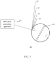
- an embodiment of this application further provides a winding machine 50.
- the winding machine 50 includes:
- the first electrode plate 22 may be the anode plate described in the foregoing embodiments, and the second electrode plate 23 may be the cathode plate described in the foregoing embodiments.
- the first electrode plate 22 is a cathode plate, and the second electrode plate 23 is an anode plate. This is not limited herein.
- centerlines of the anode plate and the cathode plate of the battery cell can remain aligned, that is, an error between a centerline of the first electrode plate 22 and/or the second electrode plate 23 and a preset centerline is kept within a predetermined range.
- centerlines of the anode plate and the cathode plate are wound on a same line during the battery cell winding process. Further, alignment of the anode plate and the cathode plate in the wound electrode assembly is also guaranteed.
- the foregoing deviation correction apparatus 10 is used to perform deviation correction for the first electrode plate 22 and the second electrode plate 23, so that an error between a centerline of the first electrode plate 22 and/or the second electrode plate 23 and a preset centerline is kept within a predetermined range, thereby ensuring alignment of the anode plate and the cathode plate in a wound electrode assembly, which improves a yield of superior wound cells, reduces scrapping of the wound cells caused by a difference in the width of the electrode plate 20, reduces difficulty of operation by a staff member, and further improves the quality of the wound cells.
- winding machine 50 may alternatively include more components, and the structure shown in FIG. 5 does not limit the implementation of the winding machine 50.
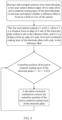
- FIG. 6 is a schematic diagram of a deviation correction process corresponding to the deviation correction scheme shown in FIG. 3 .
- the deviation correction process includes: detecting, by a line scan camera in real time, edge positions of two sides of an active material coating layer of an electrode plate during a belt transport process of the electrode plate 20 (a moving process of the electrode plate on a conveyor belt), and calculating distances from the reference label 111 fixed in a field of view of the camera.
- the line scan camera outputs centerline positions of the active material coating layer of the electrode plate in real time to the deviation correction mechanism 13.
- the deviation correction mechanism 13 can perform deviation correction in real time according to a value calculated for centerline detection, to ensure a deviation correction effect of the active material coating layer of the electrode plate during the battery cell winding process.
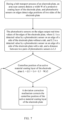
- FIG. 7 is a schematic diagram of a deviation correction process corresponding to the deviation correction scheme shown in FIG. 4 .
- the deviation correction process includes: detecting, by edge sensors on two sides of an electrode plate, edge positions of the electrode plate during a belt transport process of the electrode plate 20 (a moving process of the electrode plate on a conveyor belt), and detecting, by an area scan camera, a width of a protective coating layer of the electrode plate. Photoelectric sensors output edge positions of two sides of the electrode plate, and the area scan camera outputs the width of the protective coating layer of the electrode plate, so that a centerline position parameter of the active material coating layer of the electrode plate is calculated and given to the deviation correction mechanism 13.
- the deviation correction mechanism 13 can perform deviation correction in real time according to a value calculated for centerline detection, to ensure a deviation correction effect of the active material coating layer of the electrode plate during the battery cell winding process.
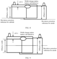
- FIG. 8 is a schematic diagram of edge position deviation correction provided in an embodiment of this application, that is, a deviation correction scheme used in prior art. If this deviation correction scheme is used, corresponding edges of the electrode plate are used as deviation correction references for the anode and the cathode. Without manual intervention, after the deviation correction mechanism 13 performs deviation correction, a result of the anode enclosing the cathode on the top of the battery cell may be out of specification, resulting in a defective battery cell being scrapped. Therefore, it is necessary to manually adjust the deviation correction reference to ensure the quality of battery cells.
- FIG. 9 is a schematic diagram of center position deviation correction used in an embodiment of this application.
- a centerline of an effective electrode plate width is used as a reference.
- the deviation correction mechanism 13 performs deviation correction based on a centerline of an effective electrode plate width, and the abnormal width part is divided to two sides, which reduces a probability that a result of the anode enclosing the cathode of the battery cell is out of specification, so that the width change of the incoming material can be more effectively handled without manual intervention.
- AT 11 shown in FIG. 8 and FIG. 9 is a ceramic edge of a horizontal cathode, which is a part of the cathode plate, and the corresponding coating layer may be a protective coating layer of the cathode plate or a non-protective coating layer. This is not limited herein.
- the center position deviation correction scheme in this embodiment of this application can achieve more effective and accurate deviation correction, making centerlines of the anode plate and the cathode plate of the battery cell remain aligned, which improves a yield of superior wound cells, reduces scrapping of the wound cells caused by a difference in the width of the electrode plate, reduces difficulty of operation by a staff member, and further improves the quality of the wound cells.
Landscapes
- Engineering & Computer Science (AREA)
- Chemical & Material Sciences (AREA)
- General Physics & Mathematics (AREA)
- Physics & Mathematics (AREA)
- Manufacturing & Machinery (AREA)
- Chemical Kinetics & Catalysis (AREA)
- Electrochemistry (AREA)
- General Chemical & Material Sciences (AREA)
- Health & Medical Sciences (AREA)
- Life Sciences & Earth Sciences (AREA)
- Analytical Chemistry (AREA)
- Biochemistry (AREA)
- General Health & Medical Sciences (AREA)
- Textile Engineering (AREA)
- Immunology (AREA)
- Pathology (AREA)
- Battery Electrode And Active Subsutance (AREA)
- Coating Apparatus (AREA)
- Length Measuring Devices By Optical Means (AREA)
Abstract

Description
- This application relates to the battery field, and specifically, to a deviation correction apparatus and a winding machine.
- In the winding process of a battery cell, in order to improve the quality of a wound cell, deviation correction is performed by a deviation correction mechanism for an electrode plate.
- In the prior art, an edge position deviation correction technology is used, with an edge of a side without a tab as a deviation correction reference. In this deviation correction method, after a deviation is corrected by a deviation correction mechanism, it is still necessary to manually adjust the deviation correction reference to ensure the quality of the battery cell.
- Therefore, efficient and accurate deviation correction for the electrode plate cannot be implemented by using existing deviation correction methods.
- This application is intended to provide a deviation correction apparatus and a winding machine, so as to implement efficient and accurate deviation correction for an electrode plate.
- According to a first aspect, this application provides a deviation correction apparatus for deviation correction of an electrode plate, the electrode plate including a coating layer; where the deviation correction apparatus includes: a width detecting apparatus for detecting a width of the coating layer; a processor communicatively connected with the width detecting apparatus, configured to determine a centerline position of the electrode plate based on the width of the coating layer; and a deviation correction mechanism, configured to perform deviation correction for the electrode plate based on the centerline position of the electrode plate and a preset standard centerline position.
- In the technical solution in this embodiment of this application, the width of the coating layer is detected to determine the centerline position of the electrode plate, and then the deviation correction is performed based on the centerline position and the preset standard centerline position. The width of the coating layer on the electrode plate may represent an effective electrode plate width, and a centerline position determined based on the width may represent the centerline position of the electrode plate. As compared with existing deviation correction schemes, a centerline of the electrode plate is used as a reference in center position deviation correction. When a width of the electrode plate is abnormal, the abnormal width part can be evenly divided to two sides of the electrode plate, so that centerlines of an anode plate and a cathode plate of the battery cell remain aligned, thereby avoiding that a result of the anode enclosing the cathode of the battery cell is out of specification after deviation correction, and the width change of the electrode plate can be more effectively handled. In addition, automatic deviation correction is performed by the deviation correction mechanism based on the centerline position, without manual intervention. Therefore, efficient and accurate deviation correction for the electrode plate can be implemented in the technical solution.
- In some embodiments, the width detecting apparatus includes: a first detecting apparatus, where the first detecting apparatus has a detection range greater than a width of the electrode plate; and a reference label, where the reference label is provided on one side of the electrode plate, and the reference label is within the detection range of the first detecting apparatus; where the first detecting apparatus is configured to detect a distance between an edge of the coating layer and the reference label.
- In the technical solution in this embodiment of this application, with the reference label being provided on one side of the electrode plate, the first detecting apparatus efficiently detects the width of the coating layer by detecting the distance between an edge of the coating layer and the reference label.
- In some embodiments, the coating layer includes a first coating layer and a second coating layer disposed adjacently to each other in a preset direction; the first detecting apparatus is configured to detect a first distance between the reference label and an edge of the first coating layer on a side close to the reference label and a second distance between the reference label and an edge of the second coating layer on a side close to the reference label; and the processor is configured to determine a distance between the centerline position of the electrode plate and the reference label based on the first distance and the second distance, and determine a centerline position of the electrode plate based on the distance between the centerline position of the electrode plate and the reference label and a position of the reference label.
- In the technical solution in this embodiment of this application, the first detecting apparatus separately detects the first distance and the second distance based on the first coating layer and the second coating layer disposed adjacently to each other in the preset direction, can determine a distance between the centerline position of the electrode plate and the reference label based on the first distance and the second distance, and can efficiently and accurately determine a centerline position of the electrode plate based on the distance.
- In some embodiments, the distance between the centerline position of the electrode plate and the reference label is expressed as: L = (L1 + L2)/2, where L1 is the first distance, and L2 is the second distance.
- In the technical solution in this embodiment of this application, because the first coating layer and the second coating layer are disposed adjacently to each other in the preset direction, the distance between the centerline position of the electrode plate and the reference label can be determined simply by taking half-sum of the first distance and the second distance.
- In some embodiments, the first coating layer is an active material coating layer of the electrode plate and the second coating layer is a protective coating layer of the electrode plate.
- In the technical solution in this embodiment of this application, the active material coating layer of the electrode plate is equivalent to a target coating layer for which deviation correction needs to be performed, and the protective coating layer of the electrode plate is equivalent to a protective layer of the electrode plate. Through the foregoing deviation correction method, a centerline position of the target coating layer for which deviation correction needs to be performed is determined efficiently and accurately.
- In some embodiments, the first detecting apparatus is a line scan camera.
- In the technical solution in this embodiment of this application, the line scan camera can be used to implement width detection in a large range, ensuring efficient detection of the width of the coating layer.
- In some embodiments, the coating layer includes the first coating layer and the second coating layer disposed adjacently to each other in the preset direction; the width detecting apparatus includes: a first edge detecting apparatus, configured to detect a first detection value of a side edge of the first coating layer away from the second coating layer; a second edge detecting apparatus, configured to detect a second detection value of a side edge of the second coating layer away from the first coating layer; and a second detecting apparatus, configured to detect a width of the second coating layer in the preset direction; and the processor is configured to: obtain a spacing between a disposed position of the first edge detecting apparatus and a disposed position of the second edge detecting apparatus; based on the first detection value, the second detection value, the spacing, and the width of the second coating layer in the preset direction, determine a distance between the centerline position of the electrode plate and the side edge of the first coating layer away from the second coating layer; and determine a centerline position of the electrode plate based on a position on the side edge of the first coating layer away from the second coating layer and the distance.
- In the technical solution in this embodiment of this application, the first edge detecting apparatus is used to detect the first detection value, the second edge detecting apparatus is used to detect the second detection value, and the second detecting apparatus is used to detect the width of the second coating layer. Then, the processor determines the distance between the centerline position of the electrode plate and the side edge of the first coating layer away from the second coating layer based on the first detection value, the second detection value, the spacing, and the width of the second coating layer, and efficiently and accurately determines the centerline position of the electrode plate based on the distance. Because detection can be performed for an edge of a coating layer, when the electrode plate includes a plurality of coating layers, the processor can be adapted to accurately determine a width of a specific coating layer and a centerline position of the specific coating layer.
- In some embodiments, the distance is expressed as: L = (L3 + L4 + L5 - W)/2, where L3 is the first detection value, L4 is the second detection value, L5 is the spacing, and W is the width of the second coating layer in the preset direction.
- In the technical solution in this embodiment of this application, a distance is accurately determined by using the foregoing formula for distance calculation.
- In some embodiments, the first coating layer is an active material coating layer of the electrode plate and the second coating layer is a protective coating layer of the electrode plate.
- In the technical solution in this embodiment of this application, the active material coating layer of the electrode plate is equivalent to a target coating layer for which deviation correction needs to be performed, and the protective coating layer of the electrode plate is equivalent to a protective layer of the electrode plate. Through the foregoing deviation correction method, a centerline position of the target coating layer for which deviation correction needs to be performed is determined efficiently and accurately.
- In some embodiments, the first edge detecting apparatus and the second edge detecting apparatus are photoelectric sensors, and the second detecting apparatus is an area scan camera.
- In the technical solution in this embodiment of this application, the photoelectric sensors can be used to efficiently determine a corresponding edge detection value, and the area scan camera can be used to efficiently detect a width in a small range.
- According to a second aspect, this application provides a winding machine, including: a winding mandrel, configured to wind a first electrode plate, a separator, and a second electrode plate; and the deviation correction apparatus according to the first aspect and any one of the implementations of the first aspect, configured to perform deviation correction for the first electrode plate and the second electrode plate, so that an error between a centerline of the first electrode plate and/or the second electrode plate and a preset centerline is kept within a predetermined range, thereby ensuring alignment of the first electrode plate and the second electrode plate in a wound electrode assembly.
- In the technical solutions in the embodiments of this application, the foregoing deviation correction apparatus is used to perform deviation correction for the first electrode plate and the second electrode plate, so that an error between a centerline of the first electrode plate and/or the second electrode plate and a preset centerline is kept within a predetermined range, thereby ensuring alignment of the first electrode plate and the second electrode plate in a wound electrode assembly, which improves a yield of superior wound cells, reduces scrapping of the wound cells caused by a difference in the width of the electrode plate, reduces difficulty of operation by a staff member, and further improves the quality of the wound cells.
- In order to describe the technical solutions in the embodiments of this application more clearly, the following briefly describes the accompanying drawings required for describing the embodiments of this application. It is appreciated that the accompanying drawings below only show some embodiments of this application and thus should not be considered as limitations on the scope. Persons of ordinary skill in the art may still derive other related drawings from the accompanying drawings without creative efforts.
-
FIG. 1 is a schematic structural diagram of a deviation correction apparatus according to an embodiment of this application; -
FIG. 2 is a schematic diagram of an electrode plate and a width detecting apparatus according to an embodiment of this application; -
FIG. 3 is a schematic diagram of an electrode plate and a width detecting apparatus according to an embodiment of this application; -
FIG. 4 is a schematic diagram of an electrode plate and a width detecting apparatus according to an embodiment of this application; -
FIG. 5 is a schematic structural diagram of a winding machine according to an embodiment of this application; -
FIG. 6 is a diagram of a deviation correction process according to an embodiment of this application; -
FIG. 7 is a diagram of a deviation correction process according to an embodiment of this application; -
FIG. 8 is a schematic diagram of a prior-art deviation correction scheme provided in this application; and -
FIG. 9 is a schematic diagram of a deviation correction scheme according to an embodiment of this application. - Reference signs: 10. deviation correction apparatus; 11. width detecting apparatus; 110. first detecting apparatus; 111. reference label; 112. first edge detecting apparatus; 113. second edge detecting apparatus; 114. second detecting apparatus; 12. processor; 13. deviation correction mechanism; 20. electrode plate; 21. coating layer; 210. first coating layer; 211. second coating layer; 22. first electrode plate; 23. second electrode plate; 30. separator; 50. winding machine; and 51. winding mandrel.
- The following describes in detail the embodiments of technical solutions in this application with reference to the accompanying drawings. The following embodiments are merely used to describe the technical solutions in this application more explicitly, and therefore they are merely used as examples and do not constitute any limitation on the protection scope of this application.
- Unless otherwise defined, all technical and scientific terms used herein shall have the same meanings as commonly understood by persons skilled in the art to which this application belongs. The terms used herein are merely intended to describe the specific embodiments but not intended to constitute any limitation on this application. The terms "include", "comprise", and any other variations thereof in the specification, the claims and the foregoing brief description of drawings of this application are intended to cover a non-exclusive inclusion.
- In the descriptions of the embodiments of this application, the terms "first", "second", and the like are merely intended to distinguish between different objects, and shall not be understood as any indication or implication of relative importance or any implicit indication of the number, specific sequence, or primary-secondary relationship of the technical features indicated. In the descriptions of the embodiments of this application, "a plurality of" means at least two unless otherwise specifically stated.
- In this specification, reference to "embodiment" means that specific features, structures, or characteristics described with reference to the embodiment may be incorporated in at least one embodiment of this application. The word "embodiment" appearing in various places in the specification does not necessarily refer to the same embodiment or an independent or alternative embodiment that is exclusive of other embodiments. Persons skilled in the art explicitly and implicitly understand that the embodiments described herein may combine with another embodiment.
- In the descriptions of the embodiments of this application, the term "and/or" describes only an association relationship for describing associated objects and represents that three relationships may exist. For example, A and/or B may represent the following three cases: A alone, both A and B, and B alone. In addition, a character "/" in this specification generally indicates an "or" relationship between contextually associated objects.
- In the descriptions of the embodiments of this application, the term "a plurality of" means more than two (inclusive). Similarly, "a plurality of groups" means more than two (inclusive) groups, and "a plurality of pieces" means more than two (inclusive) pieces.
- In the descriptions of the embodiments of this application, the orientations or positional relationships indicated by the technical terms "center", "longitudinal", "transverse", "length", "width", "thickness", "upper", "lower", "front", "rear", "left", "right", "perpendicular", "horizontal", "top", "bottom", "inside", "outside", "clockwise", "counterclockwise", "axial", " radial", "circumferential", and the like are based on the orientations or positional relationships as shown in the accompanying drawings. These terms are merely for ease and brevity of description of the embodiments of this application rather than indicating or implying that the apparatuses or elements mentioned needs to have specific orientations or needs to be constructed or manipulated according to specific orientations, and therefore shall not be construed as any limitation on the embodiments of this application.
- In the descriptions of the embodiments of this application, unless otherwise specified and defined explicitly, the terms "mount", "connect", "join", and "fasten" should be understood in their general senses. For example, they may refer to a fixed connection, a detachable connection, or an integral connection, may refer to a mechanical connection or electrical connection, and may refer to a direct connection, an indirect connection via an intermediate medium, or an internal communication or interaction between two elements. Persons of ordinary skill in the art can understand specific meanings of these terms in the embodiments of this application as appropriate to specific situations.
- Currently, from a perspective of market development, application of batteries is becoming more and more extensive. Batteries have been widely used in energy storage power supply systems such as hydroelectric power plants, thermal power plants, wind power plants, and solar power plants, and many other fields including electric transportation tools such as electric bicycles, electric motorcycles, and electric vehicles, military equipment, and aerospace. With continuous expansion of application fields of batteries, market demands for the batteries are also expanding.
- In the winding and formation processes of a battery, in order to improve the quality of a wound cell, deviation correction may be performed by a deviation correction mechanism for an electrode plate.
- In existing deviation correction mechanisms or methods, an edge position deviation correction technology is used, with an edge of a side of the electrode plate without a tab as a deviation correction reference. After deviation correction by a deviation correction mechanism, a width of an anode plate and/or a cathode plate will change. If only an edge of the electrode plate is used as a reference for deviation correction, a result of the anode enclosing the cathode on the tab side of the battery cell may be out of specification, resulting in a defective battery cell being scrapped. Therefore, it is necessary to manually adjust the deviation correction reference to ensure the quality of battery cells.
- Thus, the existing deviation correction technology cannot essentially achieve effective deviation correction of the electrode plate, thereby resulting in the fact that the quality of the battery cells cannot be guaranteed.
- After careful consideration by the applicant, the reason why the prior art cannot implement effective deviation correction is edge position deviation correction being used based on an edge of a side without a tab. Edge position deviation correction does not take an effective width of the electrode plate into account, but considers only an edge position of the electrode plate. In this way, in the edge position deviation correction based on the edge of the side without a tab, the deviation correction is not performed based on the effective width of the electrode plate. Therefore, when the electrode plate changes in width, manual adjustment is required to avoid the abnormality of the electrode plate width.
- The deviation correction reference of the edge position deviation correction is not an effective width of the electrode plate. Therefore, if the deviation correction is performed based on electrode plate positions that can represent the effective width, no matter how the width of the electrode plate changes, no manual adjustment is required.
- Based on this, in the technical solutions in the embodiments of this application, a width of a coating layer on an electrode plate is detected to determine a centerline position of the electrode plate, and then the deviation correction is performed based on the centerline position and a preset standard centerline position. The width of the coating layer on the electrode plate can represent the effective electrode plate width. For example, the electrode plate generally includes one or more coating layers provided in a preset direction. When there is one coating layer provided, the coating layer may cover an entire surface of the electrode plate. In this case, the width of the coating layer is the effective electrode plate width of the electrode plate. When there are a plurality of coating layers provided, the plurality of coating layers jointly cover the entire surface of the module. In this case, a width of a specific coating layer (a coating layer occupying most of the width) may be regarded as the effective electrode plate width of the electrode plate. Then, a centerline position determined based on the width may represent the centerline position of the effective electrode plate width.
- Therefore, in this technical solution, the centerline of the effective electrode plate width is used as the deviation correction reference. When the width of the electrode plate is abnormal, the deviation correction apparatus performs deviation correction based on the centerline of the effective electrode plate width, and the abnormal width part is evenly divided to two sides, so that centerlines of effective electrode plate areas of the anode plate and the cathode plate of the battery cell remain aligned, thereby avoiding that a result of the anode enclosing the cathode of the battery cell is out of specification, and the width change of the electrode plate can be more effectively handled. In addition, no manual intervention is required in the deviation correction.
- The technical solution provided by the embodiments of this application may be applied in the winding process of the battery, to implement deviation correction of the electrode plate by using the deviation correction apparatus and to implement the winding and formation of the battery cell after deviation correction by using the winding machine.
- In an embodiment of this application, the electrode plate includes a coating layer. In some embodiments, only one coating layer is provided on the electrode plate. In some other embodiments, a plurality of coating layers are provided on the electrode plate.
- Based on the descriptions of the foregoing inventive ideas and the application scenarios, the following is described with reference to
FIG. 1 and FIG. 2. FIG. 1 is a schematic structural diagram of adeviation correction apparatus 10 according to an embodiment of this application, andFIG. 2 is a schematic diagram of anelectrode plate 20. Thedeviation correction apparatus 10 is applied to theelectrode plate 20, theelectrode plate 20 includes acoating layer 21, and thedeviation correction apparatus 10 includes a width detecting apparatus 11, a processor 12, and adeviation correction mechanism 13. - The width detecting apparatus 11 is configured to detect a width of the
coating layer 21. - The processor 12 is communicatively connected with the width detecting apparatus 11 and is configured to determine a centerline position of the
electrode plate 20 based on the width of thecoating layer 21. - The
deviation correction mechanism 13 is configured to perform deviation correction for theelectrode plate 20 based on the centerline position of theelectrode plate 20 and a preset standard centerline position. - In some embodiments, the
electrode plate 20 includes onecoating layer 21, and the width detecting apparatus 11 detects a width of thecoating layer 21. Correspondingly, the processor 12 determines a centerline position of theelectrode plate 20 based on the width of thecoating layer 21. - In some embodiments, the
electrode plate 20 includes a plurality of coating layers 21, and the width detecting apparatus 11 needs to detect widths of the plurality of coating layers 21. Correspondingly, the processor 12 determines a centerline position of theelectrode plate 20 based on the widths of the plurality of coating layers 21. - The
deviation correction mechanism 13 is configured to compare the preset standard centerline position and the detected centerline position of theelectrode plate 20 to obtain a deviation therebetween, and then perform deviation correction on the centerline position based on the deviation. - In some embodiments, the
deviation correction mechanism 13 may include a controller and a deviation correction motor. The controller is configured to determine a deviation correction strategy of the deviation correction motor according to the deviation between the preset standard centerline position and the detected centerline position of theelectrode plate 20, and then control the deviation correction motor based on the deviation correction strategy, so that the deviation correction motor can drive theelectrode plate 20 to move, and then make the centerline position of theelectrode plate 20 meet a requirement for the standard centerline position. - For example, if the detected centerline position is shifted to the left compared with the standard centerline position, then the
electrode plate 20 can be controlled to move to the right for a distance by a deviation correction motor to avoid the deviation, so that the centerline position of the electrode plate meets the requirement for the standard centerline position. - In some other embodiments, based on the centerline position of the
electrode plate 20 and the preset standard centerline position, thedeviation correction mechanism 13 may alternatively use other implementations to correct the deviation. This is not limited in this embodiment of this application. - In the technical solution in the embodiments of this application, the width of the coating layer is detected to determine the centerline position of the
electrode plate 20, and then the deviation correction is performed based on the centerline position and the preset standard centerline position. The width of the coating layer on theelectrode plate 20 may represent an effective electrode plate width, and a centerline position determined based on the width may represent the centerline position of theelectrode plate 20. As compared with existing deviation correction schemes, a centerline of theelectrode plate 20 is used as a reference in center position deviation correction. When a width of theelectrode plate 20 is abnormal, the abnormal width part can be evenly divided to two sides of theelectrode plate 20, so that centerlines of the anode plate and the cathode plate of the battery cell remain aligned, thereby avoiding that a result of the anode enclosing the cathode of the battery cell is out of specification after deviation correction so that the width change of theelectrode plate 20 can be more effectively handled. In addition, automatic deviation correction is performed by thedeviation correction mechanism 13 based on the centerline position, without manual intervention. Therefore, efficient and accurate deviation correction for the electrode plate can be implemented in thetechnical solution 20. - Refer to
FIG. 2 . In an optional implementation, the width detecting apparatus 11 includes a first detectingapparatus 110 and areference label 111. The first detectingapparatus 110 has a detection range N greater than a width M of theelectrode plate 20. Thereference label 111 is provided on one side of theelectrode plate 20, and thereference label 111 is within the detection range N of the first detectingapparatus 110. The first detectingapparatus 110 is configured to detect a distance between thereference label 111 and an edge of the coating layer on a side away from thereference label 111. - In some embodiments, if only one
coating layer 21 is provided on theelectrode plate 20, the first detectingapparatus 110 may detect distances between edges of thecoating layer 21 on two sides and thereference label 111. - In some other embodiments, if a plurality of coating layers 21 are provided in a preset direction on the
electrode plate 20, the first detectingapparatus 110 may detect distances between thereference label 111 and edges of the plurality of coating layers 21 on a side close to thereference label 111, respectively. - In different implementations, based on the distances between corresponding edges of the coating layers 21 and the
reference label 111, a distance between a centerline position of theelectrode plate 20 and a position of thereference label 111 can be determined, and then based on a disposed position of thereference label 111, a centerline position of theelectrode plate 20 can be determined. - In the technical solution in the embodiments of this application, with the
reference label 111 being provided on one side of theelectrode plate 20, the first detectingapparatus 110 efficiently detects the width of thecoating layer 21 by detecting the distance between an edge of the coating layer and thereference label 111, and then based on a position of thereference label 111, a centerline position of theelectrode plate 20 can be determined. - It can be understood that when there are a plurality of coating layers 21, only the center of a specific coating layer may be the center of the effective width of the
electrode plate 20. In this case, if noreference label 111 is provided, the center of the specific coating layer cannot be determined. Therefore, thereference label 111 provided can be used not only for determining the center position of theelectrode plate 20 with a single coating layer, but also for determining the center position of theelectrode plate 20 with a plurality of coating layers. - Refer to
FIG. 3 . In an optional implementation, thecoating layer 21 includes afirst coating layer 210 and asecond coating layer 211 disposed adjacently to each other in a preset direction. In this case, the first detectingapparatus 110 is configured to detect a first distance L1 between thereference label 111 and an edge of thefirst coating layer 210 on a side close to thereference label 111 and a second distance L2 between thereference label 111 and an edge of thesecond coating layer 211 on a side close to thereference label 111; and the processor 12 is configured to determine a distance L between the centerline position of theelectrode plate 20 and thereference label 111 based on the first distance L1 and the second distance L2, and determine a centerline position (that is, a dotted line position in the figure) of theelectrode plate 20 based on the distance L between the centerline position of theelectrode plate 20 and thereference label 111 and a position of thereference label 111. - In such implementation, the preset direction may be from left to right, from right to left, from top to bottom, from bottom to top, or the like. This is not limited herein.
- As can be seen from
FIG. 3 , although twocoating layers 21 are included inFIG. 3 , the effective width of theelectrode plate 20 is the width of thefirst coating layer 210, and the effective electrode plate width calculated is the width of thefirst coating layer 210, which means that a width of a specific coating layer is regarded as the effective width of theelectrode plate 20. Such implementation is suitable for an application scenario in which width change of theelectrode plate 20 is related to thefirst coating layer 210 but not to thesecond coating layer 211. - In some other embodiments, if the width change of the
electrode plate 20 involves width changes of a plurality of coating layers 21, the widths of the plurality of coating layers 21 should be collectively regarded as the effective width of theelectrode plate 20. - In the technical solution in the embodiments of this application, the first detecting
apparatus 110 separately detects the first distance L1 and the second distance L2 based on thefirst coating layer 210 and thesecond coating layer 211 disposed adjacently to each other in the preset direction, can determine a distance L between the centerline position of theelectrode plate 20 and thereference label 111 based on the first distance L1 and the second distance L2, and can efficiently and accurately determine a centerline position of theelectrode plate 20 based on the distance L. - In
FIG. 3 , based on values of the first distance L1 and the second distance L2, in an optional implementation, the distance L between the centerline position of theelectrode plate 20 and thereference label 111 is expressed as: L = (L1 + L2)/2. - As shown in
FIG. 3 , it can be seen that L = (L2 - L1)/2 + L1, which can be simplified to get: L = (L 1 + L2)/2. - In the technical solution in the embodiments of this application, because the
first coating layer 210 and thesecond coating layer 211 are disposed adjacently to each other in the preset direction, the distance L between the centerline position of theelectrode plate 20 and thereference label 111 can be determined simply by taking half-sum of the first distance L1 and the second distance L2 (simplified determining method). - Based on such method for determining the distance, it can be understood that when the
coating layer 21 includes only onecoating layer 21, the first distance L1 may be equivalent to a distance L between thereference label 111 and an edge of the coating layer on a side close to thereference label 111, and the second distance L2 may be equivalent to a distance between thereference label 111 and an edge of thecoating layer 21 on a side away from thereference label 111. Therefore, the distance between the centerline position of theelectrode plate 20 and thereference label 111 in this case can still be calculated by the above calculation formula, but L2 represents a distance between thereference label 111 and an edge of thecoating layer 21 on a side away from thereference label 111. - In this embodiment of this application, the distances should be understood as the shortest distances detected between two components, that is, excluding a distance measured in an oblique direction.
- In an optional implementation, when the
electrode plate 20 is an anode plate, thefirst coating layer 210 is an active material coating layer of the electrode plate, and thesecond coating layer 211 is a protective coating layer of the electrode plate. - It can be understood that when the
electrode plate 20 is a cathode plate, thefirst coating layer 210 andsecond coating layer 211 correspond to a coating layer arrangement of the cathode plate. - In the technical solution in the embodiments of this application, the active material coating layer of the electrode plate is equivalent to a target coating layer for which deviation correction needs to be performed, and the protective coating layer of the electrode plate is equivalent to a protective layer of the
electrode plate 20, which also means that a width of the active material coating layer of the electrode plate is the effective width of theelectrode plate 20. Through the foregoing deviation correction method, a centerline position of the target coating layer for which deviation correction needs to be performed is determined efficiently and accurately. - In addition, in some embodiments, the
electrode plate 20 may also include more coating layers 21. In this case, on the basis of ensuring that the distance between the centerline position of theelectrode plate 20 and thereference label 111 can be determined based on distances between at least one side edge of each of the coating layers 21 and thereference label 111, the formula for calculating the distance or the method for detecting the distance can be flexibly set. This is not limited in this embodiment of this application. - In this embodiment of this application, the largest detection range of the first detecting
apparatus 110 should meet the requirement for the farthest distance between an edge of thecoating layer 21 and thereference label 111. For example: the largest detection range of the first detectingapparatus 110 should be greater than a distance between thereference label 111 and an edge of thecoating layer 21 on a side farthest away from thereference label 111. - In some embodiments, the first detecting
apparatus 110 may be a line scan camera. - A line scan camera is a camera that uses a line scan image sensor and implements distance detection based on a two-dimensional image. The line scan camera is used in the following two scenarios: 1. a scenario in which a field of view to be detected is an elongated ribbon, which is mostly used for inspection on a roller; and 2. a scenario in which an extremely large field of view or extremely high precision is required
- In the technical solution in the embodiments of this application, the line scan camera can be used to implement width detection in a large range, ensuring efficient detection of the width of the
coating layer 21. - An area scan camera is a camera that can capture an image all at once and acquire images in a timely manner. The camera has a wide range of applications, such as for measurement of area, shape, size, position, and even temperature. This camera can quickly and accurately capture two-dimensional image information and has a very intuitive image measurement effect.
- Compared with the line scan camera, the area scan camera has a smaller measurement range and different applicable measurement objects.
- Therefore, in some other embodiments, if the farthest distance between an edge of the
coating layer 21 and thereference label 111 is not very large, a detecting apparatus with a small detection range may alternatively be used in this case, such as an area scan camera. This is not limited herein. - In some embodiments, other distance detecting apparatuses may alternatively be used to detect a distance between an edge of the
coating layer 21 and thereference label 111, such as a laser sensor and an infrared sensor. This is not limited in this embodiment of this application. - In addition, the
reference label 111 is only used as a distance detection reference and can be flexibly implemented in a variety of manners, for example, as an identification plate, an identification line, or other identification objects. This is not limited herein. - As described in the foregoing embodiments, the
coating layer 21 on theelectrode plate 20 may be a single coating layer or a plurality of coating layers. When a plurality of coating layers are present on theelectrode plate 20, in addition to the foregoing implementations, other implementations may be used to determine a centerline position of theelectrode plate 20. - Refer to
FIG. 4 . In an optional implementation, thecoating layer 21 includes afirst coating layer 210 and asecond coating layer 211 disposed adjacently to each other in a preset direction. The width detecting apparatus 11 includes a firstedge detecting apparatus 112, a secondedge detecting apparatus 113, and a second detectingapparatus 114. The firstedge detecting apparatus 112 is configured to detect a first detection value L3 of a side edge of thefirst coating layer 210 away from thesecond coating layer 211. The secondedge detecting apparatus 113 is configured to detect a second detection value L4 of a side edge of thesecond coating layer 211 away from thefirst coating layer 210. The second detectingapparatus 114 is configured to detect a width W of the second coating layer in the preset direction. - The processor 12 is configured to: obtain a spacing L5 between a disposed position of the first
edge detecting apparatus 112 and a disposed position of the secondedge detecting apparatus 113; based on the first detection value L3, the second detection value L4, the spacing L5, and the width W, determine a distance L between the centerline position of theelectrode plate 20 and the side edge of the first coating layer away from the second coating layer; and determine a centerline position of theelectrode plate 20 based on a position on the side edge of thefirst coating layer 210 away from thesecond coating layer 211 and the distance L. - In such implementation, for how the
first coating layer 210 and thesecond coating layer 211 are disposed, refer to the descriptions in the foregoing embodiments. Details are not repeated herein. - The first
edge detecting apparatus 112 can directly acquire the first detection value L3. The secondedge detecting apparatus 113 can directly acquire the second detection value L4. - The second detecting
apparatus 114 detects a width of thesecond coating layer 211 in the preset direction, that is, W in the figure. In some embodiments, if thesecond coating layer 211 has a regular shape, the widths of different positions of thesecond coating layer 211 are consistent, and the second detectingapparatus 114 may be provided at any position of thesecond coating layer 211 in a preset direction. - In some other embodiments, if the
second coating layer 211 has an irregular shape, for example, has a protruding tab portion, the widths of different positions of thesecond coating layer 211 may be inconsistent. In this case, the second detectingapparatus 114 may be provided at a specified position of thesecond coating layer 211 in the preset direction. A width of the specified position should be consistent with widths of most positions of thesecond coating layer 211 in the preset direction. For example: the specified position cannot be a protruding position of the tab. - As shown in
FIG. 4 , if only the first detection value L3, the second detection value L4, and the width W are detected, the centerline position cannot be determined. Therefore, a spacing L5 between disposed positions of the two edge detecting apparatuses also needs to be determined. - Assuming that the first detection value L3 is a distance between one side of the first
edge detecting apparatus 112 and a corresponding edge, and that the second detection value L4 is a distance between one side of the secondedge detecting apparatus 113 and a corresponding edge, then the spacing L5 between the disposed positions of the two edge detecting apparatuses should be: a distance between the one side of the firstedge detecting apparatus 112 and the one side of the secondedge detecting apparatus 113. - Further, the processor 12 can determine a distance L between the centerline position of the
electrode plate 20 and the side edge of thefirst coating layer 210 away from thesecond coating layer 211 based on the first detection value L3, the second detection value L4, the spacing L5, and the width W, and can determine a centerline position of theelectrode plate 20 based on the distance L and in combination with a position on the side edge of thefirst coating layer 210 away from thesecond coating layer 211. - In the technical solution in the embodiments of this application, the first
edge detecting apparatus 112 is used to detect the first detection value L3, the secondedge detecting apparatus 113 is used to detect the second detection value L4, and the second detectingapparatus 114 is used to detect the width W of the second coating layer. Then, the processor 12 determines the distance L between the centerline position of theelectrode plate 20 and the side edge of thefirst coating layer 210 away from thesecond coating layer 211 based on the first detection value L3, the second detection value L4, the spacing L5, and the width W of the second coating layer, and efficiently and accurately determines a centerline position of theelectrode plate 20 based on the distance L. - In an optional implementation, the distance L between the centerline position of the
electrode plate 20 and a side edge of the first coating layer away from the second coating layer is expressed as: L = (L3 + L4 + L5 - W)/2. - In the technical solution in the embodiments of this application, a distance is accurately determined by using the foregoing formula for distance calculation.
- In such implementation, the
first coating layer 210 may be an active material coating layer of the electrode plate, and thesecond coating layer 211 may be a protective coating layer of the electrode plate. - In the technical solution in the embodiments of this application, the active material coating layer of the electrode plate is equivalent to a target coating layer for which deviation correction needs to be performed, and the protective coating layer of the electrode plate is equivalent to a protective layer of the
electrode plate 20, which means that a width of the active material coating layer of the electrode plate is the effective width of theelectrode plate 20. Through the foregoing deviation correction method, a centerline position of the target coating layer for which deviation correction needs to be performed is determined efficiently and accurately. - In an optional implementation, the first
edge detecting apparatus 112 and the secondedge detecting apparatus 113 are photoelectric sensors, and the second detectingapparatus 114 is an area scan camera. - A photoelectric sensor is a device that converts optical signals into electrical signals and is able to implement accurate distance detection based on the photoelectric effect. Therefore, the photoelectric sensor can implement distance detection between one side of the photoelectric sensor and a corresponding edge, to obtain an edge detection value.
- In the technical solution in the embodiments of this application, the photoelectric sensors can be used to efficiently determine a corresponding edge detection value, and the area scan camera can be used to efficiently detect a width in a small range.
- In some other embodiments, the first
edge detecting apparatus 112 and the secondedge detecting apparatus 113 may alternatively be other sensors capable of edge detection, such as a laser sensor and an infrared sensor. This is not limited herein. - In addition, the area scan camera may also be implemented by other detecting apparatuses capable of width detection, for example, a laser sensor and an infrared sensor or the like which are respectively disposed on two side edges of the
second coating layer 211. However, in this case, the width of thesecond coating layer 211 needs to be determined in combination with the detection values of the sensors on the two side edges. This is not limited in this embodiment of this application. - Referring to
FIG. 5 , an embodiment of this application further provides a windingmachine 50. The windingmachine 50 includes: - a winding
mandrel 51, configured to wind afirst electrode plate 22, aseparator 30, and asecond electrode plate 23; and - a
deviation correction apparatus 10, configured to perform deviation correction for thefirst electrode plate 22 and thesecond electrode plate 23, so that an error between a centerline of thefirst electrode plate 22 and/or thesecond electrode plate 23 and a preset centerline is kept within a predetermined range, thereby ensuring alignment of thefirst electrode plate 22 and thesecond electrode plate 23 in a wound electrode assembly. - The
first electrode plate 22 may be the anode plate described in the foregoing embodiments, and thesecond electrode plate 23 may be the cathode plate described in the foregoing embodiments. Alternatively, thefirst electrode plate 22 is a cathode plate, and thesecond electrode plate 23 is an anode plate. This is not limited herein. - It should be noted that the implementation of the
deviation correction apparatus 10 inFIG. 5 is not unique. Therefore, no specific structure of thedeviation correction apparatus 10 is shown inFIG. 5 . - In combination with the descriptions of the
deviation correction apparatus 10 in the foregoing embodiments, it can be seen that through the deviation correction by thedeviation correction apparatus 10, centerlines of the anode plate and the cathode plate of the battery cell can remain aligned, that is, an error between a centerline of thefirst electrode plate 22 and/or thesecond electrode plate 23 and a preset centerline is kept within a predetermined range. In other words, centerlines of the anode plate and the cathode plate are wound on a same line during the battery cell winding process. Further, alignment of the anode plate and the cathode plate in the wound electrode assembly is also guaranteed. - In the technical solution in the embodiments of this application, the foregoing
deviation correction apparatus 10 is used to perform deviation correction for thefirst electrode plate 22 and thesecond electrode plate 23, so that an error between a centerline of thefirst electrode plate 22 and/or thesecond electrode plate 23 and a preset centerline is kept within a predetermined range, thereby ensuring alignment of the anode plate and the cathode plate in a wound electrode assembly, which improves a yield of superior wound cells, reduces scrapping of the wound cells caused by a difference in the width of theelectrode plate 20, reduces difficulty of operation by a staff member, and further improves the quality of the wound cells. - It can be understood that the winding
machine 50 may alternatively include more components, and the structure shown inFIG. 5 does not limit the implementation of the windingmachine 50. - For more ease of understanding of the technical solution provided by the embodiments of this application, refer to
FIG. 6 , which is a schematic diagram of a deviation correction process corresponding to the deviation correction scheme shown inFIG. 3 . - The deviation correction process includes: detecting, by a line scan camera in real time, edge positions of two sides of an active material coating layer of an electrode plate during a belt transport process of the electrode plate 20 (a moving process of the electrode plate on a conveyor belt), and calculating distances from the
reference label 111 fixed in a field of view of the camera. The line scan camera outputs centerline positions of the active material coating layer of the electrode plate in real time to thedeviation correction mechanism 13. When a width of the active material coating layer of the electrode plate changes or theelectrode plate 20 deviates during the belt transport process, thedeviation correction mechanism 13 can perform deviation correction in real time according to a value calculated for centerline detection, to ensure a deviation correction effect of the active material coating layer of the electrode plate during the battery cell winding process. - Refer to
FIG. 7 , which is a schematic diagram of a deviation correction process corresponding to the deviation correction scheme shown inFIG. 4 . - The deviation correction process includes: detecting, by edge sensors on two sides of an electrode plate, edge positions of the electrode plate during a belt transport process of the electrode plate 20 (a moving process of the electrode plate on a conveyor belt), and detecting, by an area scan camera, a width of a protective coating layer of the electrode plate. Photoelectric sensors output edge positions of two sides of the electrode plate, and the area scan camera outputs the width of the protective coating layer of the electrode plate, so that a centerline position parameter of the active material coating layer of the electrode plate is calculated and given to the
deviation correction mechanism 13. When the width of the active material coating layer of the electrode plate changes or the electrode plate deviates during the belt transport process, thedeviation correction mechanism 13 can perform deviation correction in real time according to a value calculated for centerline detection, to ensure a deviation correction effect of the active material coating layer of the electrode plate during the battery cell winding process. - Refer to
FIG. 8 , which is a schematic diagram of edge position deviation correction provided in an embodiment of this application, that is, a deviation correction scheme used in prior art. If this deviation correction scheme is used, corresponding edges of the electrode plate are used as deviation correction references for the anode and the cathode. Without manual intervention, after thedeviation correction mechanism 13 performs deviation correction, a result of the anode enclosing the cathode on the top of the battery cell may be out of specification, resulting in a defective battery cell being scrapped. Therefore, it is necessary to manually adjust the deviation correction reference to ensure the quality of battery cells. - Refer to
FIG. 9 , which is a schematic diagram of center position deviation correction used in an embodiment of this application. With the center position deviation correction method, a centerline of an effective electrode plate width is used as a reference. When a width of an incoming material is abnormal, thedeviation correction mechanism 13 performs deviation correction based on a centerline of an effective electrode plate width, and the abnormal width part is divided to two sides, which reduces a probability that a result of the anode enclosing the cathode of the battery cell is out of specification, so that the width change of the incoming material can be more effectively handled without manual intervention. - AT 11 shown in
FIG. 8 and FIG. 9 is a ceramic edge of a horizontal cathode, which is a part of the cathode plate, and the corresponding coating layer may be a protective coating layer of the cathode plate or a non-protective coating layer. This is not limited herein. - Therefore, compared with existing edge position deviation correction schemes, the center position deviation correction scheme in this embodiment of this application can achieve more effective and accurate deviation correction, making centerlines of the anode plate and the cathode plate of the battery cell remain aligned, which improves a yield of superior wound cells, reduces scrapping of the wound cells caused by a difference in the width of the electrode plate, reduces difficulty of operation by a staff member, and further improves the quality of the wound cells.
- The foregoing descriptions are merely the embodiments of this application, but are not intended to limit the protection scope of this application. Persons skilled in the art understand that this application may have various modifications and variations. Any modification, equivalent replacement, and improvement made without departing from the spirit and principle of this application shall fall within the protection scope of this application.
Claims (11)
- A deviation correction apparatus (10) for deviation correction of an electrode plate (20), the electrode plate (20) comprising a coating layer (21); characterized in that the deviation correction apparatus (10) comprises:a width detecting apparatus (11) for detecting a width of the coating layer (21);a processor (12) communicatively connected with the width detecting apparatus (11), configured to determine a centerline position of the electrode plate (20) based on the width of the coating layer (21); anda deviation correction mechanism (13), configured to perform deviation correction for the electrode plate (20) based on the centerline position of the electrode plate (20) and a preset standard centerline position.
- The deviation correction apparatus (10) according to claim 1, characterized in that the width detecting apparatus (11) comprises:a first detecting apparatus (110), wherein the first detecting apparatus (110) has a detection range greater than a width of the electrode plate (20); anda reference label (111), wherein the reference label (111) is provided on a side of the electrode plate (20), and the reference label (111) is within the detection range of the first detecting apparatus (110);wherein the first detecting apparatus (110) is configured to detect a distance between an edge of the coating layer (21) and the reference label (111).
- The deviation correction apparatus (10) according to claim 2, characterized in that the coating layer (21) comprises a first coating layer (210) and a second coating layer (211) disposed adjacently to each other in a preset direction;the first detecting apparatus (110) is configured to detect a first distance between the reference label (111) and an edge of the first coating layer (210) on a side close to the reference label (111) and a second distance between the reference label (111) and an edge of the second coating layer (211) on a side close to the reference label (111); andthe processor (12) is configured to determine a distance between the centerline position of the electrode plate (20) and the reference label (111) based on the first distance and the second distance, and determine a centerline position of the electrode plate (20) based on the distance between the centerline position of the electrode plate (20) and the reference label (111) and a position of the reference label (111).
- The deviation correction apparatus (10) according to claim 3, characterized in that the distance between the centerline position of the electrode plate (20) and the reference label (111) is expressed as: L = (L1 + L2)/2, wherein L1 is the first distance, and L2 is the second distance.
- The deviation correction apparatus (10) according to claim 3, characterized in that the first coating layer (210) is an active material coating layer of the electrode plate (20) and the second coating layer (211) is a protective coating layer of the electrode plate (20).
- The deviation correction apparatus (10) according to any one of claims 2 to 5, characterized in that the first detecting apparatus (110) is a line scan camera.
- The deviation correction apparatus (10) according to claim 1, characterized in that the coating layer (21) comprises a first coating layer (210) and a second coating layer (211) disposed adjacently to each other in a preset direction; and the width detecting apparatus (11) comprises:a first edge detecting apparatus (112), configured to detect a first detection value of a side edge of the first coating layer (210) away from the second coating layer (211);a second edge detecting apparatus (113), configured to detect a second detection value of a side edge of the second coating layer (211) away from the first coating layer (210); anda second detecting apparatus (114), configured to detect a width of the second coating layer (211) in the preset direction; andthe processor (12) is configured to: obtain a spacing between a disposed position of the first edge detecting apparatus (112) and a disposed position of the second edge detecting apparatus (113); based on the first detection value, the second detection value, the spacing, and the width of the second coating layer (211) in the preset direction, determine a distance between the centerline position of the electrode plate (20) and the side edge of the first coating layer (210) away from the second coating layer (211); and determine a centerline position of the electrode plate (20) based on a position on the side edge of the first coating layer (210) away from the second coating layer (211) and the distance.
- The deviation correction apparatus (10) according to claim 7, characterized in that the distance is expressed as:
L = (L3 + L4 + L5 - W)/2, wherein L3 is the first detection value, L4 is the second detection value, L5 is the spacing, and W is the width of the second coating layer (211) in the preset direction. - The deviation correction apparatus (10) according to claim 7, characterized in that the first coating layer (210) is an active material coating layer of the electrode plate (20) and the second coating layer (211) is a protective coating layer of the electrode plate (20).
- The deviation correction apparatus (10) according to claim 7 or 8, characterized in that the first edge detecting apparatus (112) and the second edge detecting apparatus (113) are photoelectric sensors, and the second detecting apparatus (114) is an area scan camera.
- A winding machine (50), characterized by comprising:a winding mandrel (51), configured to wind a first electrode plate (22), a separator (30), and a second electrode plate (23); andthe deviation correction apparatus (10) according to any one of claims 1 to 10, configured to perform deviation correction for the first electrode plate (22) and the second electrode plate (23), so that an error between a centerline of the first electrode plate (22) and/or the second electrode plate (23) and a preset centerline is kept within a predetermined range, thereby ensuring alignment of the first electrode plate (22) and the second electrode plate (23) in a wound electrode assembly.
Applications Claiming Priority (1)
| Application Number | Priority Date | Filing Date | Title |
|---|---|---|---|
| CN202221068467.6U CN217086648U (en) | 2022-05-07 | 2022-05-07 | Deviation correcting device and winding machine |
Publications (1)
| Publication Number | Publication Date |
|---|---|
| EP4273984A1 true EP4273984A1 (en) | 2023-11-08 |
Family
ID=82502965
Family Applications (1)
| Application Number | Title | Priority Date | Filing Date |
|---|---|---|---|
| EP23171853.7A Pending EP4273984A1 (en) | 2022-05-07 | 2023-05-05 | Deviation correction apparatus and winding machine |
Country Status (4)
| Country | Link |
|---|---|
| US (1) | US20230356972A1 (en) |
| EP (1) | EP4273984A1 (en) |
| CN (1) | CN217086648U (en) |
| WO (1) | WO2023217040A1 (en) |
Families Citing this family (9)
| Publication number | Priority date | Publication date | Assignee | Title |
|---|---|---|---|---|
| CN217086648U (en) * | 2022-05-07 | 2022-07-29 | 宁德时代新能源科技股份有限公司 | Deviation correcting device and winding machine |
| CN115535685B (en) * | 2022-11-25 | 2023-03-21 | 钛玛科(北京)工业科技有限公司 | A method and system for correcting and controlling battery core coils |
| CN116342526B (en) * | 2023-03-17 | 2025-10-03 | 海目星激光科技集团股份有限公司 | Tab alignment adjustment method, device and battery cell cutting and winding equipment |
| CN116199023B (en) * | 2023-04-27 | 2023-09-29 | 宁德时代新能源科技股份有限公司 | Control method and device for deviation correction of winding mechanism, electronic equipment and storage medium |
| CN117533861A (en) * | 2023-11-09 | 2024-02-09 | 钛玛科(北京)工业科技有限公司 | Method and system for centering and correcting deviation of target coating |
| CN117755879A (en) * | 2023-11-21 | 2024-03-26 | 钛玛科(北京)工业科技有限公司 | A method and system for correcting and controlling target web materials |
| CN118156636B (en) * | 2024-05-09 | 2024-09-03 | 钛玛科(北京)工业科技有限公司 | Lithium battery winding closed-loop control system and method |
| CN118405523B (en) * | 2024-06-25 | 2024-09-27 | 惠州市信宇人科技有限公司 | Method and system for controlling unreeling deviation of lithium ion battery pole piece and readable storage medium |
| CN121601590A (en) * | 2024-08-23 | 2026-03-03 | 宁德时代新能源科技股份有限公司 | Electrode assembly manufacturing method and equipment, battery cell, battery and electricity utilization device |
Citations (2)
| Publication number | Priority date | Publication date | Assignee | Title |
|---|---|---|---|---|
| US20100281685A1 (en) * | 2008-01-11 | 2010-11-11 | Hideki Hori | Electrode winding apparatus and electrode winding method (as amended) |
| CN111416142B (en) * | 2020-03-31 | 2021-03-30 | 广东利元亨智能装备股份有限公司 | Correction method, device, correction control device and correction system for battery cells |
Family Cites Families (8)
| Publication number | Priority date | Publication date | Assignee | Title |
|---|---|---|---|---|
| FR2525836A1 (en) * | 1982-04-23 | 1983-10-28 | Thomson Csf | TRANSVERSE FILTER WITH CHARGE TRANSFER |
| JP2012236676A (en) * | 2011-05-11 | 2012-12-06 | Nippon Electric Glass Co Ltd | Device of correcting winding deviation of film and method of correcting winding deviation |
| CN107681202B (en) * | 2017-11-06 | 2023-05-12 | 无锡先导智能装备股份有限公司 | CCD feedback deviation correction closed-loop control method, control device and control system |
| CN109738447B (en) * | 2018-12-14 | 2021-12-21 | 惠州锂威新能源科技有限公司 | Automatic deviation rectifying method and device for battery pole piece protective adhesive |
| CN212608476U (en) * | 2020-06-05 | 2021-02-26 | 凯多智能科技(上海)有限公司 | System for realizing material width measurement by centering and rectifying |
| WO2022061610A1 (en) * | 2020-09-23 | 2022-03-31 | 宁德新能源科技有限公司 | Battery and electronic device having same |
| CN116799324A (en) * | 2022-03-18 | 2023-09-22 | 宁德时代新能源科技股份有限公司 | Winding equipment and methods |
| CN217086648U (en) * | 2022-05-07 | 2022-07-29 | 宁德时代新能源科技股份有限公司 | Deviation correcting device and winding machine |
-
2022
- 2022-05-07 CN CN202221068467.6U patent/CN217086648U/en active Active
-
2023
- 2023-05-05 EP EP23171853.7A patent/EP4273984A1/en active Pending
- 2023-05-05 US US18/312,764 patent/US20230356972A1/en active Pending
- 2023-05-06 WO PCT/CN2023/092541 patent/WO2023217040A1/en not_active Ceased
Patent Citations (2)
| Publication number | Priority date | Publication date | Assignee | Title |
|---|---|---|---|---|
| US20100281685A1 (en) * | 2008-01-11 | 2010-11-11 | Hideki Hori | Electrode winding apparatus and electrode winding method (as amended) |
| CN111416142B (en) * | 2020-03-31 | 2021-03-30 | 广东利元亨智能装备股份有限公司 | Correction method, device, correction control device and correction system for battery cells |
Also Published As
| Publication number | Publication date |
|---|---|
| WO2023217040A1 (en) | 2023-11-16 |
| US20230356972A1 (en) | 2023-11-09 |
| CN217086648U (en) | 2022-07-29 |
Similar Documents
| Publication | Publication Date | Title |
|---|---|---|
| US20230356972A1 (en) | Deviation correction apparatus and winding machine | |
| WO2024108847A1 (en) | Roller, spot inspection method and apparatus, coiled-material conveying method and apparatus, and device and medium | |
| US12175707B2 (en) | Method and device for controlling misalignment of electrode plates, electrode plates, electrochemical cell, and battery | |
| US12307719B2 (en) | Calibration scale, calibration method and apparatus, and detection method and apparatus | |
| WO2025077178A1 (en) | Die cutting and slitting system, and visual inspection method for die cutting and slitting | |
| US20230278130A1 (en) | Welding apparatus and welding device | |
| US12358746B2 (en) | Automatic electrode supply apparatus for manufacture of secondary battery and automatic electrode supply method using the same | |
| CN118168489B (en) | Dimension detection method and device, production equipment, computing equipment, medium and product | |
| US20240296544A1 (en) | Displacement detection method and apparatus, delivery apparatus, and storage medium | |
| WO2023028897A1 (en) | Battery winding method, battery winding system, battery, and electrical device | |
| KR20240042524A (en) | Method and device for detection of material strip feeding for laminators, laminators, devices and media | |
| WO2024036952A1 (en) | Calibration ruler, calibration method and apparatus, and detection method and apparatus | |
| US20240166460A1 (en) | Roller, inspection method and apparatus, coil conveying method and apparatus, device and medium | |
| US20250124568A1 (en) | Detection method and system for battery production, and production method and system for battery | |
| CN118837297B (en) | Pole defect detection system and method | |
| CN220751072U (en) | Battery cell tab detection system | |
| KR102036544B1 (en) | Device for Welding Electrode Tabs Comprising Vision Inspection Part | |
| CN210156504U (en) | Laser cross cutting coiling all-in-one | |
| US20240047639A1 (en) | Measurement device and electrode plate production system | |
| CN120095231A (en) | Pole cutting system and method | |
| EP4386362A1 (en) | Detection method and detection apparatus for electrode sheet, and stacking system | |
| US20250058486A1 (en) | Notching Device and Control Method Therefor | |
| US12630386B2 (en) | Electrode plate wrinkling detection apparatus and cell production equipment | |
| US20240150149A1 (en) | Electrode plate wrinkling detection apparatus and cell production equipment | |
| CN120761189B (en) | Elongation monitoring system and method |
Legal Events
| Date | Code | Title | Description |
|---|---|---|---|
| PUAI | Public reference made under article 153(3) epc to a published international application that has entered the european phase |
Free format text: ORIGINAL CODE: 0009012 |
|
| STAA | Information on the status of an ep patent application or granted ep patent |
Free format text: STATUS: REQUEST FOR EXAMINATION WAS MADE |
|
| 17P | Request for examination filed |
Effective date: 20230505 |
|
| AK | Designated contracting states |
Kind code of ref document: A1 Designated state(s): AL AT BE BG CH CY CZ DE DK EE ES FI FR GB GR HR HU IE IS IT LI LT LU LV MC ME MK MT NL NO PL PT RO RS SE SI SK SM TR |
|
| RAP1 | Party data changed (applicant data changed or rights of an application transferred) |
Owner name: CONTEMPORARY AMPEREX TECHNOLOGY(HONG KONG) LIMITED |
|
| STAA | Information on the status of an ep patent application or granted ep patent |
Free format text: STATUS: EXAMINATION IS IN PROGRESS |
|
| 17Q | First examination report despatched |
Effective date: 20250924 |