EP4273514A1 - System und verfahren zum bestimmen mindestens eines berechneten prozessparameters eines fluids in einer leitung - Google Patents
System und verfahren zum bestimmen mindestens eines berechneten prozessparameters eines fluids in einer leitung Download PDFInfo
- Publication number
- EP4273514A1 EP4273514A1 EP22172013.9A EP22172013A EP4273514A1 EP 4273514 A1 EP4273514 A1 EP 4273514A1 EP 22172013 A EP22172013 A EP 22172013A EP 4273514 A1 EP4273514 A1 EP 4273514A1
- Authority
- EP
- European Patent Office
- Prior art keywords
- fluid
- pipe
- determining
- nominal
- sensor
- Prior art date
- Legal status (The legal status is an assumption and is not a legal conclusion. Google has not performed a legal analysis and makes no representation as to the accuracy of the status listed.)
- Pending
Links
- 238000000034 method Methods 0.000 title claims abstract description 185
- 239000012530 fluid Substances 0.000 title claims abstract description 183
- 239000000463 material Substances 0.000 claims description 8
- 238000004590 computer program Methods 0.000 claims description 2
- 238000004364 calculation method Methods 0.000 description 14
- 238000009413 insulation Methods 0.000 description 9
- 239000007789 gas Substances 0.000 description 6
- 238000005259 measurement Methods 0.000 description 6
- 238000009529 body temperature measurement Methods 0.000 description 4
- 239000000523 sample Substances 0.000 description 4
- 238000009434 installation Methods 0.000 description 3
- 238000004458 analytical method Methods 0.000 description 2
- 230000001419 dependent effect Effects 0.000 description 2
- 230000000694 effects Effects 0.000 description 2
- 238000004519 manufacturing process Methods 0.000 description 2
- 238000013459 approach Methods 0.000 description 1
- 238000007630 basic procedure Methods 0.000 description 1
- 238000004422 calculation algorithm Methods 0.000 description 1
- 238000000576 coating method Methods 0.000 description 1
- 230000002860 competitive effect Effects 0.000 description 1
- 230000007797 corrosion Effects 0.000 description 1
- 238000005260 corrosion Methods 0.000 description 1
- 238000013461 design Methods 0.000 description 1
- 238000009792 diffusion process Methods 0.000 description 1
- 238000005553 drilling Methods 0.000 description 1
- 238000005516 engineering process Methods 0.000 description 1
- 230000003628 erosive effect Effects 0.000 description 1
- 239000002360 explosive Substances 0.000 description 1
- 238000010230 functional analysis Methods 0.000 description 1
- 239000004615 ingredient Substances 0.000 description 1
- 229910052500 inorganic mineral Inorganic materials 0.000 description 1
- 238000011326 mechanical measurement Methods 0.000 description 1
- 239000011707 mineral Substances 0.000 description 1
- 238000012821 model calculation Methods 0.000 description 1
- 238000012544 monitoring process Methods 0.000 description 1
- 238000012545 processing Methods 0.000 description 1
- 230000035945 sensitivity Effects 0.000 description 1
- 239000002341 toxic gas Substances 0.000 description 1
Images
Classifications
-
- G—PHYSICS
- G01—MEASURING; TESTING
- G01F—MEASURING VOLUME, VOLUME FLOW, MASS FLOW OR LIQUID LEVEL; METERING BY VOLUME
- G01F1/00—Measuring the volume flow or mass flow of fluid or fluent solid material wherein the fluid passes through a meter in a continuous flow
- G01F1/68—Measuring the volume flow or mass flow of fluid or fluent solid material wherein the fluid passes through a meter in a continuous flow by using thermal effects
- G01F1/684—Structural arrangements; Mounting of elements, e.g. in relation to fluid flow
- G01F1/688—Structural arrangements; Mounting of elements, e.g. in relation to fluid flow using a particular type of heating, cooling or sensing element
- G01F1/6884—Structural arrangements; Mounting of elements, e.g. in relation to fluid flow using a particular type of heating, cooling or sensing element making use of temperature dependence of optical properties
-
- G—PHYSICS
- G01—MEASURING; TESTING
- G01F—MEASURING VOLUME, VOLUME FLOW, MASS FLOW OR LIQUID LEVEL; METERING BY VOLUME
- G01F1/00—Measuring the volume flow or mass flow of fluid or fluent solid material wherein the fluid passes through a meter in a continuous flow
- G01F1/68—Measuring the volume flow or mass flow of fluid or fluent solid material wherein the fluid passes through a meter in a continuous flow by using thermal effects
-
- G—PHYSICS
- G01—MEASURING; TESTING
- G01D—MEASURING NOT SPECIALLY ADAPTED FOR A SPECIFIC VARIABLE; ARRANGEMENTS FOR MEASURING TWO OR MORE VARIABLES NOT COVERED IN A SINGLE OTHER SUBCLASS; TARIFF METERING APPARATUS; MEASURING OR TESTING NOT OTHERWISE PROVIDED FOR
- G01D21/00—Measuring or testing not otherwise provided for
- G01D21/02—Measuring two or more variables by means not covered by a single other subclass
-
- G—PHYSICS
- G01—MEASURING; TESTING
- G01F—MEASURING VOLUME, VOLUME FLOW, MASS FLOW OR LIQUID LEVEL; METERING BY VOLUME
- G01F1/00—Measuring the volume flow or mass flow of fluid or fluent solid material wherein the fluid passes through a meter in a continuous flow
- G01F1/68—Measuring the volume flow or mass flow of fluid or fluent solid material wherein the fluid passes through a meter in a continuous flow by using thermal effects
- G01F1/684—Structural arrangements; Mounting of elements, e.g. in relation to fluid flow
- G01F1/6847—Structural arrangements; Mounting of elements, e.g. in relation to fluid flow where sensing or heating elements are not disturbing the fluid flow, e.g. elements mounted outside the flow duct
-
- G—PHYSICS
- G01—MEASURING; TESTING
- G01J—MEASUREMENT OF INTENSITY, VELOCITY, SPECTRAL CONTENT, POLARISATION, PHASE OR PULSE CHARACTERISTICS OF INFRARED, VISIBLE OR ULTRAVIOLET LIGHT; COLORIMETRY; RADIATION PYROMETRY
- G01J5/00—Radiation pyrometry, e.g. infrared or optical thermometry
-
- G—PHYSICS
- G01—MEASURING; TESTING
- G01K—MEASURING TEMPERATURE; MEASURING QUANTITY OF HEAT; THERMALLY-SENSITIVE ELEMENTS NOT OTHERWISE PROVIDED FOR
- G01K1/00—Details of thermometers not specially adapted for particular types of thermometer
- G01K1/14—Supports; Fastening devices; Arrangements for mounting thermometers in particular locations
- G01K1/143—Supports; Fastening devices; Arrangements for mounting thermometers in particular locations for measuring surface temperatures
-
- G—PHYSICS
- G01—MEASURING; TESTING
- G01K—MEASURING TEMPERATURE; MEASURING QUANTITY OF HEAT; THERMALLY-SENSITIVE ELEMENTS NOT OTHERWISE PROVIDED FOR
- G01K13/00—Thermometers specially adapted for specific purposes
- G01K13/02—Thermometers specially adapted for specific purposes for measuring temperature of moving fluids or granular materials capable of flow
- G01K13/024—Thermometers specially adapted for specific purposes for measuring temperature of moving fluids or granular materials capable of flow of moving gases
-
- G—PHYSICS
- G01—MEASURING; TESTING
- G01K—MEASURING TEMPERATURE; MEASURING QUANTITY OF HEAT; THERMALLY-SENSITIVE ELEMENTS NOT OTHERWISE PROVIDED FOR
- G01K7/00—Measuring temperature based on the use of electric or magnetic elements directly sensitive to heat ; Power supply therefor, e.g. using thermoelectric elements
- G01K7/02—Measuring temperature based on the use of electric or magnetic elements directly sensitive to heat ; Power supply therefor, e.g. using thermoelectric elements using thermoelectric elements, e.g. thermocouples
-
- G—PHYSICS
- G01—MEASURING; TESTING
- G01K—MEASURING TEMPERATURE; MEASURING QUANTITY OF HEAT; THERMALLY-SENSITIVE ELEMENTS NOT OTHERWISE PROVIDED FOR
- G01K7/00—Measuring temperature based on the use of electric or magnetic elements directly sensitive to heat ; Power supply therefor, e.g. using thermoelectric elements
- G01K7/42—Circuits effecting compensation of thermal inertia; Circuits for predicting the stationary value of a temperature
- G01K7/427—Temperature calculation based on spatial modeling, e.g. spatial inter- or extrapolation
-
- G—PHYSICS
- G01—MEASURING; TESTING
- G01L—MEASURING FORCE, STRESS, TORQUE, WORK, MECHANICAL POWER, MECHANICAL EFFICIENCY, OR FLUID PRESSURE
- G01L1/00—Measuring force or stress, in general
- G01L1/20—Measuring force or stress, in general by measuring variations in ohmic resistance of solid materials or of electrically-conductive fluids; by making use of electrokinetic cells, i.e. liquid-containing cells wherein an electrical potential is produced or varied upon the application of stress
- G01L1/22—Measuring force or stress, in general by measuring variations in ohmic resistance of solid materials or of electrically-conductive fluids; by making use of electrokinetic cells, i.e. liquid-containing cells wherein an electrical potential is produced or varied upon the application of stress using resistance strain gauges
- G01L1/2287—Measuring force or stress, in general by measuring variations in ohmic resistance of solid materials or of electrically-conductive fluids; by making use of electrokinetic cells, i.e. liquid-containing cells wherein an electrical potential is produced or varied upon the application of stress using resistance strain gauges constructional details of the strain gauges
Definitions
- the invention relates to a system and method for determining at least one calculated process parameter of a fluid in a pipe.
- Industrial process sensors like flow or pressure or viscosity sensors need traditionally invasive installations, needing direct access to the process fluid.
- the invasive access involving sealed joints in the piping represents a relevant safety risk (e.g. leakage due to corrosion, erosion or mechanical damage).
- Only temperature sensors have the potential for less critical installations by using thermowells which are welded into the pipe.
- a system for calculating at least one calculated process parameter of a fluid in a pipe comprises the following: A data interface, configured for receiving nominal process parameters, wherein the nominal process parameters comprise pipe parameters and at least one fluid parameter, wherein the at least one pipe parameter comprises a geometry of the pipe and/or a material of the pipe, wherein the at least one fluid parameter comprises a nominal viscosity of the fluid, a nominal heat conductivity of the fluid, a nominal pressure of the fluid and/or a nominal velocity of the fluid.
- An invasive temperature sensor configured for determining a fluid temperature of the fluid in the pipe.
- a reference temperature sensor disposed outside of the pipe, configured for determining a reference temperature outside of the pipe.
- a surface temperature sensor disposed on a surface of the pipe, configured for determining a surface temperature of the pipe.
- a process model configured for determining at least one calculated process parameter of the fluid in the pipe by using the determined reference temperature, the determined surface temperature, the received process parameters and the determined fluid temperature.
- a process parameter for example pressure or velocity of the fluid
- a process parameter can be determined in a non-invasive way.
- Non-invasive relates to a form of sensing, wherein no probe is inserted into the pipe.
- an invasive temperature sensor is used for the determination of the process parameter, however no invasive process parameter is used. This means that no additional invasive sensor is needed beyond an the existing invasive temperature sensor to gain information on process parameters like fluid pressure or fluid velocity.
- Non-invasive as used herein, relates to a form of sensing, wherein no probe penetrates the pipe wall or protrudes into the flow of the fluid in the pipe.
- nominal process parameter comprises information about the process that is performed using the fluid and the pipe that are known, for example by predetermination or preestimation.
- the nominal process parameters are provided to the system by a data interface so that the system, in particular the process model is provided with general information about the pipe, the fluid and the process carried out itself.
- the nominal process parameters are for example stored in a database and just read out by the system. Alternatively the nominal process parameters are read out from control system information from nearby sensors. Part of the nominal process parameters (e.g. fluid information) can also be provided as input values during device setup.
- calculated process parameter relates to an estimation of the process parameter, for example fluid velocity or fluid pressure that is calculated by the process model.
- the process model instead of directly measuring a process parameter with an invasive sensor, the process model provides a calculated process parameter that is more accurate than a measuring said process parameter with a non-invasive sensor.
- the surface temperature sensor is a state-of-the-art clamp-on temperature sensor as described in Gebhardt, Jörg / Daake, Wilhelm / Ude, Peter / Schroder, Karsten / Sosale, Guruprasad: Accurate and quickly responsive surface temperature measurement: a step to widespread non-invasive T-measurement in industry, 2019, IEEE International Instrumentation and Measurement Technology Conference, I2MTC, Auckland, New Zealand, May 20-23, or by a standard cable (mineral insulated or not) thermometer, or by an IR temperature sensor.
- the reference temperature relates to a temperature outside the pipe, in a certain distance of the pipe wall's outer surface. It can be either embedded in the insulation structure or can be outside of it. In the latter case it can be an ambient temperature.
- the fluid temperature refers to the temperature of the fluid in the center of the pipe that has the largest distance to the pipe walls.
- the center of the pipe extend along the rotation axis of the pipe.
- the invasive temperature sensor extends a probe into the pipe to the center of the pipe to measure the fluid temperature. Consequently, the fluid temperature, provided by the invasive temperature sensor relates to a measured fluid temperature in the center of the pipe.
- the sensors namely the reference temperature sensor, the surface temperature sensor and the invasive temperature sensor are connected to a common electronic unit within which the processing of the signals and the process model, carrying out the calculation of the calculated process parameter, are implemented.
- the fluid is gas.
- the fluid is a compressive fluid.
- the temperature profile, or the temperature difference between the core of the flow and the pipe surface depends on the heat conductivity of the system.
- the heat conductivity in the fluid depends on various flow parameters, of which pressure has a very large effect.
- the pressure was found to be a major parameter to enable sufficient accuracy of the model calculation for the fluid temperature.
- the process model performs its full calculation locally in the system.
- at least some of the calculations are performed in a cloud service.
- the process model further preferably uses parametric look-up tables that references predetermined inputs to predetermined outputs to reduce computational capacity requirements of the process model.
- the system provides a means for non-invasively determining the pressure in fluid, in particular gas, filled pipes.
- the system can be applied to any pipe featuring at least one invasive temperature sensor, giving information on the fluid temperature at a known distance from the pipe wall.
- Such invasive temperature measurement points are often implemented with fully welded thermowells, representing a much smaller leakage risk than any pressure.
- the process model is configured for determining a Nußelt number of the fluid by using the fluid temperature and determining the at least one calculated process parameter by using the determined Nußelt number, wherein the Nußelt number depends on a Prandtl number of the fluid and a Reynolds number of the fluid, wherein the Prandtl number and the Reynolds number each depend on the at least one calculated process parameter.
- a thermal resistance of a fluid boundary layer is particularly relevant for the difference of the pipe surface temperature and the fluid temperature.
- the boundary layer in a pipe flow is generally not rigorously defined regarding its geometric extension. Nevertheless, its thermal resistance (or inverse thermal conductivity) is usually defined as the thermal resistance connecting (or separating) the inner wall temperature and the average (bulk-) temperature of the medium flowing in the pipe.
- the thermal resistance depends on the fluid density, and therefore on pressure, and also on fluid velocity in the pipe.
- the thermal resistance of the fluid boundary layer in pipe hydrodynamics can be described by the Nußelt number, Nu. It is defined as the ratio of convective to pure conductive heat conductivity across the fluid boundary layer.
- v the kinematic viscosity of the fluid
- ⁇ the thermal diffusivity of the fluid
- ⁇ the dynamic viscosity of the fluid
- ⁇ the thermal conductivity of the fluid
- cp the specific heat capacity of the fluid
- ⁇ the density of the fluid.
- the second ingredient for Nu is the Reynolds number, Re, in the situation of interest.
- Tm f T surface , T reference , R bl P , v , ⁇ , ⁇ , ⁇ , c P , d , R w d , d w i , ⁇ w i , R F d insulation i ⁇ insulation i h
- R bl is the inverse conductivity (with units: m 2 K / W) of the medium boundary layer adjacent to the inner pipe wall surface.
- R w is the inverse conductivity of the pipe wall, including possible coatings inside and outside, with thicknesses d w i , and thermal conductivities " ⁇ w i of the materials.
- R F is the inverse conductivity of the insulation layers, if any, and of outside convective boundary layers. If there is no insulation, the corresponding contribution to inverse conductivity is zero.
- Equation 4 if all but one of the independent variables on the right side of Equation 4 are known or can be estimated (this would be the parameters P N ) , the one remaining unknown variable (P C ) can be calculated by inverting the expression in Equation 4. This is possible, at least locally in the space of independent variables, under very general regularity conditions according to the implicit function theorem, well known from classical analysis (e.g. A.N. Kolmogorov, S.V. Fomin, "Elements of the theory of functions and functional analysis", Vol.s 1-2 , Martino Fine Books (2012 ).
- the invention also is to be understood to include cases when there are more influence factors than explicitly shown in Equation 4 (e.g. in complex flow situations where entry length L and roughness or friction factors (see EP 3537124 B1 ) of the pipe or other variables may play a role).
- a measured value for P and/or v, or some other estimate of P and/or v can be used for a subsequent calculation of the three dimensionless variables, leading to the determination of the accurate estimation of the fluid temperature.
- the knowledge of both temperatures can help to quantify the value of at least one of the process parameters in Equation 4 and in subsequent sections, in particular, either the fluid pressure or of the fluid velocity.
- the concept can be extended also to the measurement of the pressure in fluid tanks or vessels equipped with at least one invasive temperature measurement point.
- the nominal process parameters comprise at least one pipe parameter and at least one fluid parameter, wherein the at least one pipe parameter comprises a geometry of the pipe and/or a material of the pipe, wherein the at least one fluid parameter comprises a nominal viscosity of the fluid, a nominal heat conductivity of the fluid, a nominal pressure of the fluid and/or a nominal velocity of the fluid.
- the at least one calculated process parameter comprises a calculated pressure of the fluid, a calculated velocity of the fluid, a calculated viscosity of the fluid and/or a calculated heat conductivity of the fluid or any of the quantities mentioned in Equation 4 and subsequent sections.
- the system comprises a process parameter sensor, configured for determining at least one measured process parameter.
- the process model is configured for determining the at least one calculated process parameter by using the at least one measured process parameter.
- each additional information about the process can be used to further improve the accuracy of the calculation.
- measurements of other process parameters can enhance the accuracy of the calculation.
- the process model calculates a pressure of the fluid
- the accuracy of the calculation can be enhanced by a measurement of the velocity of the fluid, in particular by a non-invasive velocity sensor. The more additional process parameters are measured, the higher is the accuracy of the calculation of the calculated process parameter.
- the at least one measured process parameter comprises a measured pressure of the fluid, a measured velocity of the fluid, a measured viscosity of the fluid and/or a measured heat conductivity of the fluid.
- the process parameter sensor comprises a non-invasive process parameter sensor.
- Non-invasive process parameter sensors can be applied to the system, in particular to the pipe more easily and more secure than invasive process parameter sensors. Although the accuracy of the non-invasive process parameter sensors is usually worse than the accuracy of invasive process parameter sensors, each additional information for the process model enhances the calculation accuracy of the process model.
- the non-invasive process parameter sensor comprises a non-invasive velocity sensor, which is configured for determining the measured velocity of the fluid in a non-invasive way.
- the non-invasive velocity sensor is an ultrasonic sensor that is configured for determining the fluid velocity in a non-invasive way. Further preferably, the process model uses said determined fluid velocity to calculate a calculated fluid pressure.
- the non-invasive process parameter sensor is integrated into the surface temperature sensor.
- the surface temperature sensor comprises a clamping system that is configured for attaching the surface temperature sensor on a surface of the pipe.
- the non-invasive process parameter sensor can be, e.g., a non-invasive pressure sensor that is integrated into the clamping system.
- the calculated process parameter is preferably the fluid velocity.
- the fluid velocity shares a strong physical relationship with the pressure in the pipe and the fluid temperature as well as the surface temperature. Consequently, the non-invasive pressure sensor that is integrated into the surface temperature sensor provides a measured pressure of the fluid to the process model in order to calculate the calculated fluid velocity.
- the additional non-invasive process parameter sensor is attached to the pipe together with the surface temperature sensor, allowing a simple addition of the non-invasive process parameter sensor to the pipe.
- the non-invasive process parameter sensor comprises a non-invasive pressure sensor that is integrated into the clamping system by a strain gauge on a clamp strip, a tensile force sensor in the clamp or a compressive force sensor between the clamp and the pipe surface.
- a method for calculating calculated process parameters of a fluid in a pipe comprises the following steps. Receiving, by a data interface, nominal process parameters, wherein the nominal process parameters comprise pipe parameters and at least one fluid parameter, wherein the at least one pipe parameter comprises a geometry of the pipe and/or a material of the pipe, wherein the at least one fluid parameter comprises a nominal viscosity of the fluid, a nominal heat conductivity of the fluid, a nominal pressure of the fluid and/or a nominal velocity of the fluid. Determining, by an invasive temperature sensor, a fluid temperature of the fluid in the pipe. Determining, by a surface temperature sensor disposed on a surface of the pipe, the surface temperature of the pipe.
- a computer program comprises instructions, which, when the program is executed by a computer, cause the computer to carry out the steps of a method, as described herein.
- a computer-readable medium comprises instructions which, when executed by a computer, cause the computer to carry out the steps of a method, as described herein.
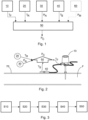
- Fig. 1 schematically shows a process model 50.
- the process model 50 is configured for determining, or in other words calculating, at least one calculated process parameter P C of a fluid F in a pipe 70 by using a determined fluid temperature T F , a determined reference temperature T R , a determined surface temperature T S and received nominal process parameters P N .
- the process model 50 gets the necessary input data from a plurality of entities connected with the process model 50. The input data is either measured, known, predetermined and/or preestimated.
- An invasive temperature sensor 10 provides the process model 50 with the fluid temperature T F .
- the fluid temperature T F that is measured by the invasive temperature sensor 10 relates to a temperature of the fluid F within the pipe 70, in particular a core temperature of the fluid F in the pipe 70.
- the invasive temperature sensor 10 comprises a probe that reaches into the pipe 70 in order to directly measure the fluid temperature T F .
- the reference temperature T R reflects the temperature outside of the pipe 70, in particular outside of an insulation of the pipe 70.
- a data interface 30 provides the process model 50 with at least one nominal process parameter P N .
- the at least one nominal process parameter P N reflects nominal properties of the process related to the fluid F in the pipe 70, or in other words, properties of the process that are known, predetermined and/or preestimated.
- the at least one nominal process parameter P N comprises at least one nominal pipe parameter, reflecting properties of the pipe 70 and at least one nominal fluid parameter, reflecting properties of the fluid F, wherein the at least one nominal pipe parameter comprises a geometry of the pipe 70 and/or a material of the pipe 70, wherein the at least one nominal fluid parameter comprises a nominal viscosity of the fluid F, a nominal heat conductivity of the fluid F, a nominal fluid pressure of the fluid F and/or a nominal fluid velocity of the fluid F.
- a non-invasive temperature sensor 40 also referred to as surface temperature sensor 40, provides the process model 50 with a surface temperature T S , being the temperature on the outer surface of the pipe 70.
- a non-invasive process parameter sensor 60 provides the process model 50 with at least one measured process parameter P M .
- the measured process parameter P M for example comprise a measured pressure P of the fluid F, a measured velocity of the fluid F, a measured viscosity of the fluid F and/or a measured heat conductivity of the fluid F.
- the process model 50 uses the at least one measured process parameter P M to further enhance the accuracy of the calculation of the calculated process parameter P C .
- Fig. 2 schematically shows a system for calculating at least one calculated process parameter P C of a fluid F in a pipe 70.
- a fluid F runs through a pipe 70.
- a process parameter for example the pressure P in the pipe 70 needs to be known.
- An invasive form of measuring the process parameter is not applicable in most situations, thus a calculation of the calculated process parameter P C is performed by the process model 50.
- the system comprises a surface temperature sensor 40 that is disposed at a pipe surface of the pipe 70.
- the surface temperature sensor 40 is able to directly determine a surface temperature T S , being the temperature of the outer surface of the pipe 70.
- the pipe 70 is surrounded by an insulation.
- the surface temperature T S relates to the temperature on the outside of the pipe 70 under the insulation.
- the system comprises a reference temperature sensor 20 that measures the reference temperature T R outside of the pipe 70, in particular outside of the insulation of the pipe 70.
- the system further comprises a data interface 30 that is configured for receiving nominal process parameters P N , wherein the nominal process parameters P N relate to nominal parameters of a process that relates to the fluid F in the pipe 70.
- the nominal process parameters P N comprise information about the fluid F and the pipe 70 that is known or can be estimated to sufficient accuracy due to the nature of the process.
- the system comprises a process model 50 that is configured to provide a calculation of the process parameter, referred to as calculated process parameter P C .
- the process model 50 uses different inputs in addition to the determined fluid temperature T F to perform an estimation algorithm that provides the calculated process parameter P C .
- the process model 50 uses the determined fluid temperature T F , the determined reference temperature T R , the determined surface temperature T S and the provided nominal process parameters P N .
- Fig. 3 schematically shows a method for determining at least one calculated process parameter P C of a fluid F in a pipe 70.
- a data interface 30 received nominal process parameters P N , wherein the nominal process parameters P N relate to nominal parameters P N of a process that relates to the fluid F in the pipe 70.
- an invasive temperature sensor 10 determined a fluid temperature T F of the fluid F in the pipe 70.
- a reference temperature sensor 20 disposed outside of the pipe 70, determines a reference temperature T R outside of the pipe 70.
- a surface temperature sensor 40 disposed at a surface of the pipe 70, determines a surface temperature T S of the pipe 70.
- a process model 50 determines at least one calculated process parameter P C of the fluid F in the pipe 70 by using the determined reference temperature T R , the determined surface temperature T S , the received nominal process parameters P N and the determined fluid temperature T F .
Landscapes
- Physics & Mathematics (AREA)
- General Physics & Mathematics (AREA)
- Fluid Mechanics (AREA)
- Spectroscopy & Molecular Physics (AREA)
- Measuring Temperature Or Quantity Of Heat (AREA)
- Pipeline Systems (AREA)
Priority Applications (3)
| Application Number | Priority Date | Filing Date | Title |
|---|---|---|---|
| EP22172013.9A EP4273514A1 (de) | 2022-05-06 | 2022-05-06 | System und verfahren zum bestimmen mindestens eines berechneten prozessparameters eines fluids in einer leitung |
| CN202310497402.6A CN117007107A (zh) | 2022-05-06 | 2023-05-05 | 用于确定管道中的流体的至少一个计算过程参数的系统和方法 |
| US18/312,909 US20230358585A1 (en) | 2022-05-06 | 2023-05-05 | System and Method for Determining at Least One Calculated Process Parameter of a Fluid in a Pipe |
Applications Claiming Priority (1)
| Application Number | Priority Date | Filing Date | Title |
|---|---|---|---|
| EP22172013.9A EP4273514A1 (de) | 2022-05-06 | 2022-05-06 | System und verfahren zum bestimmen mindestens eines berechneten prozessparameters eines fluids in einer leitung |
Publications (1)
| Publication Number | Publication Date |
|---|---|
| EP4273514A1 true EP4273514A1 (de) | 2023-11-08 |
Family
ID=81585517
Family Applications (1)
| Application Number | Title | Priority Date | Filing Date |
|---|---|---|---|
| EP22172013.9A Pending EP4273514A1 (de) | 2022-05-06 | 2022-05-06 | System und verfahren zum bestimmen mindestens eines berechneten prozessparameters eines fluids in einer leitung |
Country Status (3)
| Country | Link |
|---|---|
| US (1) | US20230358585A1 (de) |
| EP (1) | EP4273514A1 (de) |
| CN (1) | CN117007107A (de) |
Citations (3)
| Publication number | Priority date | Publication date | Assignee | Title |
|---|---|---|---|---|
| EP1014061A1 (de) * | 1998-12-21 | 2000-06-28 | Ruhrgas Aktiengesellschaft | Verfahren zur Bestimmung der über den Querschnitt einer Gasleitung gemittelten Gastemperatur |
| DE102016101862A1 (de) * | 2016-02-03 | 2017-08-03 | Dr. Ing. H.C. F. Porsche Aktiengesellschaft | Verfahren zur Bestimmung einer Temperatur, System zur Bestimmung einer Temperatur und Verwenden eines Systems zur Bestimmung einer Temperatur |
| EP3537124A1 (de) | 2018-03-08 | 2019-09-11 | ABB Schweiz AG | Verfahren zur nicht-intrusiven ermittlung einer temperatur eines durch einen leitungsabschnitt strömenden fluids |
-
2022
- 2022-05-06 EP EP22172013.9A patent/EP4273514A1/de active Pending
-
2023
- 2023-05-05 CN CN202310497402.6A patent/CN117007107A/zh active Pending
- 2023-05-05 US US18/312,909 patent/US20230358585A1/en active Pending
Patent Citations (4)
| Publication number | Priority date | Publication date | Assignee | Title |
|---|---|---|---|---|
| EP1014061A1 (de) * | 1998-12-21 | 2000-06-28 | Ruhrgas Aktiengesellschaft | Verfahren zur Bestimmung der über den Querschnitt einer Gasleitung gemittelten Gastemperatur |
| DE102016101862A1 (de) * | 2016-02-03 | 2017-08-03 | Dr. Ing. H.C. F. Porsche Aktiengesellschaft | Verfahren zur Bestimmung einer Temperatur, System zur Bestimmung einer Temperatur und Verwenden eines Systems zur Bestimmung einer Temperatur |
| EP3537124A1 (de) | 2018-03-08 | 2019-09-11 | ABB Schweiz AG | Verfahren zur nicht-intrusiven ermittlung einer temperatur eines durch einen leitungsabschnitt strömenden fluids |
| EP3537124B1 (de) | 2018-03-08 | 2021-01-27 | ABB Schweiz AG | Verfahren und system zur nicht-intrusiven ermittlung einer temperatur eines durch einen leitungsabschnitt strömenden fluids |
Also Published As
| Publication number | Publication date |
|---|---|
| US20230358585A1 (en) | 2023-11-09 |
| CN117007107A (zh) | 2023-11-07 |
Similar Documents
| Publication | Publication Date | Title |
|---|---|---|
| US20220326060A1 (en) | Method for generating a diagnostic from a deviation of a flow meter parameter | |
| CN111801556B (zh) | 用于非侵入式测定流过导管区段的流体的温度的方法 | |
| EP4273514A1 (de) | System und verfahren zum bestimmen mindestens eines berechneten prozessparameters eines fluids in einer leitung | |
| US8583397B2 (en) | Device for determination of thermal exchange coefficient and associated method | |
| Gebhardt et al. | Accurate and quickly responsive surface temperature measurement: a step to widespread non-invasive T-measurement in industry | |
| JP5018365B2 (ja) | 配管肉厚測定装置及び方法 | |
| EP0617271B1 (de) | Verfahren zur gleichzeitigen Messung der Wärmeleitfähigkeit und kinematischen Viskosität | |
| EP4273524A1 (de) | System und verfahren zum nicht-invasiven bestimmen einer fluidtemperatur | |
| US20240118225A1 (en) | Computer Implemented Method for Providing Temperature Data, a Computer Product Element and a System | |
| Sarzosa et al. | Experimental validation of relationship between fracture parameters J and CTOD for SE (B) and SE (T) specimens during ductile crack growth | |
| JPS59128429A (ja) | 耐圧部品の寿命監視法 | |
| US20240077365A1 (en) | Temperature Measurement Facility | |
| CN117849098A (zh) | 用于确定边界热阻数据的计算机实现的方法、计算机产品元件和系统 | |
| EP3583393B1 (de) | Kalorimetrische sonde und verfahren zur kalorimetrischen messung | |
| Souza et al. | Displacer-Type Liquid Level Sensor with Liquid Density Auto-Compensation | |
| USH2228H1 (en) | Temperature compensated fluid conductivity piping measurement | |
| Huster et al. | Experimental determination of the recovery factor on cylindrically flow-around temperature sensors Part 1: Determination of the recovery factor for different Reynolds-and Mach-Numbers | |
| Klason et al. | Temperature measurement in flow pipes: Comparison with single Pt-100 and multisensors | |
| Smits | Preston Probe Calibrations at High Reynolds Number |
Legal Events
| Date | Code | Title | Description |
|---|---|---|---|
| PUAI | Public reference made under article 153(3) epc to a published international application that has entered the european phase |
Free format text: ORIGINAL CODE: 0009012 |
|
| STAA | Information on the status of an ep patent application or granted ep patent |
Free format text: STATUS: THE APPLICATION HAS BEEN PUBLISHED |
|
| AK | Designated contracting states |
Kind code of ref document: A1 Designated state(s): AL AT BE BG CH CY CZ DE DK EE ES FI FR GB GR HR HU IE IS IT LI LT LU LV MC MK MT NL NO PL PT RO RS SE SI SK SM TR |
|
| STAA | Information on the status of an ep patent application or granted ep patent |
Free format text: STATUS: REQUEST FOR EXAMINATION WAS MADE |
|
| GRAP | Despatch of communication of intention to grant a patent |
Free format text: ORIGINAL CODE: EPIDOSNIGR1 |
|
| STAA | Information on the status of an ep patent application or granted ep patent |
Free format text: STATUS: GRANT OF PATENT IS INTENDED |
|
| 17P | Request for examination filed |
Effective date: 20240408 |
|
| RBV | Designated contracting states (corrected) |
Designated state(s): AL AT BE BG CH CY CZ DE DK EE ES FI FR GB GR HR HU IE IS IT LI LT LU LV MC MK MT NL NO PL PT RO RS SE SI SK SM TR |