EP4273514A1 - System and method for determining at least one calculated process parameter of a fluid in a pipe - Google Patents
System and method for determining at least one calculated process parameter of a fluid in a pipe Download PDFInfo
- Publication number
- EP4273514A1 EP4273514A1 EP22172013.9A EP22172013A EP4273514A1 EP 4273514 A1 EP4273514 A1 EP 4273514A1 EP 22172013 A EP22172013 A EP 22172013A EP 4273514 A1 EP4273514 A1 EP 4273514A1
- Authority
- EP
- European Patent Office
- Prior art keywords
- fluid
- pipe
- determining
- nominal
- sensor
- Prior art date
- Legal status (The legal status is an assumption and is not a legal conclusion. Google has not performed a legal analysis and makes no representation as to the accuracy of the status listed.)
- Granted
Links
Images
Classifications
-
- G—PHYSICS
- G01—MEASURING; TESTING
- G01F—MEASURING VOLUME, VOLUME FLOW, MASS FLOW OR LIQUID LEVEL; METERING BY VOLUME
- G01F1/00—Measuring the volume flow or mass flow of fluid or fluent solid material wherein the fluid passes through a meter in a continuous flow
- G01F1/68—Measuring the volume flow or mass flow of fluid or fluent solid material wherein the fluid passes through a meter in a continuous flow by using thermal effects
- G01F1/684—Structural arrangements; Mounting of elements, e.g. in relation to fluid flow
- G01F1/688—Structural arrangements; Mounting of elements, e.g. in relation to fluid flow using a particular type of heating, cooling or sensing element
- G01F1/6884—Structural arrangements; Mounting of elements, e.g. in relation to fluid flow using a particular type of heating, cooling or sensing element making use of temperature dependence of optical properties
-
- G—PHYSICS
- G01—MEASURING; TESTING
- G01F—MEASURING VOLUME, VOLUME FLOW, MASS FLOW OR LIQUID LEVEL; METERING BY VOLUME
- G01F1/00—Measuring the volume flow or mass flow of fluid or fluent solid material wherein the fluid passes through a meter in a continuous flow
- G01F1/68—Measuring the volume flow or mass flow of fluid or fluent solid material wherein the fluid passes through a meter in a continuous flow by using thermal effects
-
- G—PHYSICS
- G01—MEASURING; TESTING
- G01D—MEASURING NOT SPECIALLY ADAPTED FOR A SPECIFIC VARIABLE; ARRANGEMENTS FOR MEASURING TWO OR MORE VARIABLES NOT COVERED IN A SINGLE OTHER SUBCLASS; TARIFF METERING APPARATUS; MEASURING OR TESTING NOT OTHERWISE PROVIDED FOR
- G01D21/00—Measuring or testing not otherwise provided for
- G01D21/02—Measuring two or more variables by means not covered by a single other subclass
-
- G—PHYSICS
- G01—MEASURING; TESTING
- G01F—MEASURING VOLUME, VOLUME FLOW, MASS FLOW OR LIQUID LEVEL; METERING BY VOLUME
- G01F1/00—Measuring the volume flow or mass flow of fluid or fluent solid material wherein the fluid passes through a meter in a continuous flow
- G01F1/68—Measuring the volume flow or mass flow of fluid or fluent solid material wherein the fluid passes through a meter in a continuous flow by using thermal effects
- G01F1/684—Structural arrangements; Mounting of elements, e.g. in relation to fluid flow
- G01F1/6847—Structural arrangements; Mounting of elements, e.g. in relation to fluid flow where sensing or heating elements are not disturbing the fluid flow, e.g. elements mounted outside the flow duct
-
- G—PHYSICS
- G01—MEASURING; TESTING
- G01J—MEASUREMENT OF INTENSITY, VELOCITY, SPECTRAL CONTENT, POLARISATION, PHASE OR PULSE CHARACTERISTICS OF INFRARED, VISIBLE OR ULTRAVIOLET LIGHT; COLORIMETRY; RADIATION PYROMETRY
- G01J5/00—Radiation pyrometry, e.g. infrared or optical thermometry
-
- G—PHYSICS
- G01—MEASURING; TESTING
- G01K—MEASURING TEMPERATURE; MEASURING QUANTITY OF HEAT; THERMALLY-SENSITIVE ELEMENTS NOT OTHERWISE PROVIDED FOR
- G01K1/00—Details of thermometers not specially adapted for particular types of thermometer
- G01K1/14—Supports; Fastening devices; Arrangements for mounting thermometers in particular locations
- G01K1/143—Supports; Fastening devices; Arrangements for mounting thermometers in particular locations for measuring surface temperatures
-
- G—PHYSICS
- G01—MEASURING; TESTING
- G01K—MEASURING TEMPERATURE; MEASURING QUANTITY OF HEAT; THERMALLY-SENSITIVE ELEMENTS NOT OTHERWISE PROVIDED FOR
- G01K13/00—Thermometers specially adapted for specific purposes
- G01K13/02—Thermometers specially adapted for specific purposes for measuring temperature of moving fluids or granular materials capable of flow
-
- G—PHYSICS
- G01—MEASURING; TESTING
- G01K—MEASURING TEMPERATURE; MEASURING QUANTITY OF HEAT; THERMALLY-SENSITIVE ELEMENTS NOT OTHERWISE PROVIDED FOR
- G01K13/00—Thermometers specially adapted for specific purposes
- G01K13/02—Thermometers specially adapted for specific purposes for measuring temperature of moving fluids or granular materials capable of flow
- G01K13/024—Thermometers specially adapted for specific purposes for measuring temperature of moving fluids or granular materials capable of flow of moving gases
-
- G—PHYSICS
- G01—MEASURING; TESTING
- G01K—MEASURING TEMPERATURE; MEASURING QUANTITY OF HEAT; THERMALLY-SENSITIVE ELEMENTS NOT OTHERWISE PROVIDED FOR
- G01K7/00—Measuring temperature based on the use of electric or magnetic elements directly sensitive to heat ; Power supply therefor, e.g. using thermoelectric elements
- G01K7/02—Measuring temperature based on the use of electric or magnetic elements directly sensitive to heat ; Power supply therefor, e.g. using thermoelectric elements using thermoelectric elements, e.g. thermocouples
-
- G—PHYSICS
- G01—MEASURING; TESTING
- G01K—MEASURING TEMPERATURE; MEASURING QUANTITY OF HEAT; THERMALLY-SENSITIVE ELEMENTS NOT OTHERWISE PROVIDED FOR
- G01K7/00—Measuring temperature based on the use of electric or magnetic elements directly sensitive to heat ; Power supply therefor, e.g. using thermoelectric elements
- G01K7/42—Circuits effecting compensation of thermal inertia; Circuits for predicting the stationary value of a temperature
- G01K7/427—Temperature calculation based on spatial modeling, e.g. spatial inter- or extrapolation
-
- G—PHYSICS
- G01—MEASURING; TESTING
- G01L—MEASURING FORCE, STRESS, TORQUE, WORK, MECHANICAL POWER, MECHANICAL EFFICIENCY, OR FLUID PRESSURE
- G01L1/00—Measuring force or stress, in general
- G01L1/20—Measuring force or stress, in general by measuring variations in ohmic resistance of solid materials or of electrically-conductive fluids; by making use of electrokinetic cells, i.e. liquid-containing cells wherein an electrical potential is produced or varied upon the application of stress
- G01L1/22—Measuring force or stress, in general by measuring variations in ohmic resistance of solid materials or of electrically-conductive fluids; by making use of electrokinetic cells, i.e. liquid-containing cells wherein an electrical potential is produced or varied upon the application of stress using resistance strain gauges
- G01L1/2287—Measuring force or stress, in general by measuring variations in ohmic resistance of solid materials or of electrically-conductive fluids; by making use of electrokinetic cells, i.e. liquid-containing cells wherein an electrical potential is produced or varied upon the application of stress using resistance strain gauges constructional details of the strain gauges
Definitions
- the invention relates to a system and method for determining at least one calculated process parameter of a fluid in a pipe.
- Industrial process sensors like flow or pressure or viscosity sensors need traditionally invasive installations, needing direct access to the process fluid.
- the invasive access involving sealed joints in the piping represents a relevant safety risk (e.g. leakage due to corrosion, erosion or mechanical damage).
- Only temperature sensors have the potential for less critical installations by using thermowells which are welded into the pipe.
- a system for calculating at least one calculated process parameter of a fluid in a pipe comprises the following: A data interface, configured for receiving nominal process parameters, wherein the nominal process parameters comprise pipe parameters and at least one fluid parameter, wherein the at least one pipe parameter comprises a geometry of the pipe and/or a material of the pipe, wherein the at least one fluid parameter comprises a nominal viscosity of the fluid, a nominal heat conductivity of the fluid, a nominal pressure of the fluid and/or a nominal velocity of the fluid.
- An invasive temperature sensor configured for determining a fluid temperature of the fluid in the pipe.
- a reference temperature sensor disposed outside of the pipe, configured for determining a reference temperature outside of the pipe.
- a surface temperature sensor disposed on a surface of the pipe, configured for determining a surface temperature of the pipe.
- a process model configured for determining at least one calculated process parameter of the fluid in the pipe by using the determined reference temperature, the determined surface temperature, the received process parameters and the determined fluid temperature.
- a process parameter for example pressure or velocity of the fluid
- a process parameter can be determined in a non-invasive way.
- Non-invasive relates to a form of sensing, wherein no probe is inserted into the pipe.
- an invasive temperature sensor is used for the determination of the process parameter, however no invasive process parameter is used. This means that no additional invasive sensor is needed beyond an the existing invasive temperature sensor to gain information on process parameters like fluid pressure or fluid velocity.
- Non-invasive as used herein, relates to a form of sensing, wherein no probe penetrates the pipe wall or protrudes into the flow of the fluid in the pipe.
- nominal process parameter comprises information about the process that is performed using the fluid and the pipe that are known, for example by predetermination or preestimation.
- the nominal process parameters are provided to the system by a data interface so that the system, in particular the process model is provided with general information about the pipe, the fluid and the process carried out itself.
- the nominal process parameters are for example stored in a database and just read out by the system. Alternatively the nominal process parameters are read out from control system information from nearby sensors. Part of the nominal process parameters (e.g. fluid information) can also be provided as input values during device setup.
- calculated process parameter relates to an estimation of the process parameter, for example fluid velocity or fluid pressure that is calculated by the process model.
- the process model instead of directly measuring a process parameter with an invasive sensor, the process model provides a calculated process parameter that is more accurate than a measuring said process parameter with a non-invasive sensor.
- the surface temperature sensor is a state-of-the-art clamp-on temperature sensor as described in Gebhardt, Jörg / Daake, Wilhelm / Ude, Peter / Schroder, Karsten / Sosale, Guruprasad: Accurate and quickly responsive surface temperature measurement: a step to widespread non-invasive T-measurement in industry, 2019, IEEE International Instrumentation and Measurement Technology Conference, I2MTC, Auckland, New Zealand, May 20-23, or by a standard cable (mineral insulated or not) thermometer, or by an IR temperature sensor.
- the reference temperature relates to a temperature outside the pipe, in a certain distance of the pipe wall's outer surface. It can be either embedded in the insulation structure or can be outside of it. In the latter case it can be an ambient temperature.
- the fluid temperature refers to the temperature of the fluid in the center of the pipe that has the largest distance to the pipe walls.
- the center of the pipe extend along the rotation axis of the pipe.
- the invasive temperature sensor extends a probe into the pipe to the center of the pipe to measure the fluid temperature. Consequently, the fluid temperature, provided by the invasive temperature sensor relates to a measured fluid temperature in the center of the pipe.
- the sensors namely the reference temperature sensor, the surface temperature sensor and the invasive temperature sensor are connected to a common electronic unit within which the processing of the signals and the process model, carrying out the calculation of the calculated process parameter, are implemented.
- the fluid is gas.
- the fluid is a compressive fluid.
- the temperature profile, or the temperature difference between the core of the flow and the pipe surface depends on the heat conductivity of the system.
- the heat conductivity in the fluid depends on various flow parameters, of which pressure has a very large effect.
- the pressure was found to be a major parameter to enable sufficient accuracy of the model calculation for the fluid temperature.
- the process model performs its full calculation locally in the system.
- at least some of the calculations are performed in a cloud service.
- the process model further preferably uses parametric look-up tables that references predetermined inputs to predetermined outputs to reduce computational capacity requirements of the process model.
- the system provides a means for non-invasively determining the pressure in fluid, in particular gas, filled pipes.
- the system can be applied to any pipe featuring at least one invasive temperature sensor, giving information on the fluid temperature at a known distance from the pipe wall.
- Such invasive temperature measurement points are often implemented with fully welded thermowells, representing a much smaller leakage risk than any pressure.
- the process model is configured for determining a Nußelt number of the fluid by using the fluid temperature and determining the at least one calculated process parameter by using the determined Nußelt number, wherein the Nußelt number depends on a Prandtl number of the fluid and a Reynolds number of the fluid, wherein the Prandtl number and the Reynolds number each depend on the at least one calculated process parameter.
- a thermal resistance of a fluid boundary layer is particularly relevant for the difference of the pipe surface temperature and the fluid temperature.
- the boundary layer in a pipe flow is generally not rigorously defined regarding its geometric extension. Nevertheless, its thermal resistance (or inverse thermal conductivity) is usually defined as the thermal resistance connecting (or separating) the inner wall temperature and the average (bulk-) temperature of the medium flowing in the pipe.
- the thermal resistance depends on the fluid density, and therefore on pressure, and also on fluid velocity in the pipe.
- the thermal resistance of the fluid boundary layer in pipe hydrodynamics can be described by the Nußelt number, Nu. It is defined as the ratio of convective to pure conductive heat conductivity across the fluid boundary layer.
- v the kinematic viscosity of the fluid
- ⁇ the thermal diffusivity of the fluid
- ⁇ the dynamic viscosity of the fluid
- ⁇ the thermal conductivity of the fluid
- cp the specific heat capacity of the fluid
- ⁇ the density of the fluid.
- the second ingredient for Nu is the Reynolds number, Re, in the situation of interest.
- Tm f T surface , T reference , R bl P , v , ⁇ , ⁇ , ⁇ , c P , d , R w d , d w i , ⁇ w i , R F d insulation i ⁇ insulation i h
- R bl is the inverse conductivity (with units: m 2 K / W) of the medium boundary layer adjacent to the inner pipe wall surface.
- R w is the inverse conductivity of the pipe wall, including possible coatings inside and outside, with thicknesses d w i , and thermal conductivities " ⁇ w i of the materials.
- R F is the inverse conductivity of the insulation layers, if any, and of outside convective boundary layers. If there is no insulation, the corresponding contribution to inverse conductivity is zero.
- Equation 4 if all but one of the independent variables on the right side of Equation 4 are known or can be estimated (this would be the parameters P N ) , the one remaining unknown variable (P C ) can be calculated by inverting the expression in Equation 4. This is possible, at least locally in the space of independent variables, under very general regularity conditions according to the implicit function theorem, well known from classical analysis (e.g. A.N. Kolmogorov, S.V. Fomin, "Elements of the theory of functions and functional analysis", Vol.s 1-2 , Martino Fine Books (2012 ).
- the invention also is to be understood to include cases when there are more influence factors than explicitly shown in Equation 4 (e.g. in complex flow situations where entry length L and roughness or friction factors (see EP 3537124 B1 ) of the pipe or other variables may play a role).
- a measured value for P and/or v, or some other estimate of P and/or v can be used for a subsequent calculation of the three dimensionless variables, leading to the determination of the accurate estimation of the fluid temperature.
- the knowledge of both temperatures can help to quantify the value of at least one of the process parameters in Equation 4 and in subsequent sections, in particular, either the fluid pressure or of the fluid velocity.
- the concept can be extended also to the measurement of the pressure in fluid tanks or vessels equipped with at least one invasive temperature measurement point.
- the nominal process parameters comprise at least one pipe parameter and at least one fluid parameter, wherein the at least one pipe parameter comprises a geometry of the pipe and/or a material of the pipe, wherein the at least one fluid parameter comprises a nominal viscosity of the fluid, a nominal heat conductivity of the fluid, a nominal pressure of the fluid and/or a nominal velocity of the fluid.
- the at least one calculated process parameter comprises a calculated pressure of the fluid, a calculated velocity of the fluid, a calculated viscosity of the fluid and/or a calculated heat conductivity of the fluid or any of the quantities mentioned in Equation 4 and subsequent sections.
- the system comprises a process parameter sensor, configured for determining at least one measured process parameter.
- the process model is configured for determining the at least one calculated process parameter by using the at least one measured process parameter.
- each additional information about the process can be used to further improve the accuracy of the calculation.
- measurements of other process parameters can enhance the accuracy of the calculation.
- the process model calculates a pressure of the fluid
- the accuracy of the calculation can be enhanced by a measurement of the velocity of the fluid, in particular by a non-invasive velocity sensor. The more additional process parameters are measured, the higher is the accuracy of the calculation of the calculated process parameter.
- the at least one measured process parameter comprises a measured pressure of the fluid, a measured velocity of the fluid, a measured viscosity of the fluid and/or a measured heat conductivity of the fluid.
- the process parameter sensor comprises a non-invasive process parameter sensor.
- Non-invasive process parameter sensors can be applied to the system, in particular to the pipe more easily and more secure than invasive process parameter sensors. Although the accuracy of the non-invasive process parameter sensors is usually worse than the accuracy of invasive process parameter sensors, each additional information for the process model enhances the calculation accuracy of the process model.
- the non-invasive process parameter sensor comprises a non-invasive velocity sensor, which is configured for determining the measured velocity of the fluid in a non-invasive way.
- the non-invasive velocity sensor is an ultrasonic sensor that is configured for determining the fluid velocity in a non-invasive way. Further preferably, the process model uses said determined fluid velocity to calculate a calculated fluid pressure.
- the non-invasive process parameter sensor is integrated into the surface temperature sensor.
- the surface temperature sensor comprises a clamping system that is configured for attaching the surface temperature sensor on a surface of the pipe.
- the non-invasive process parameter sensor can be, e.g., a non-invasive pressure sensor that is integrated into the clamping system.
- the calculated process parameter is preferably the fluid velocity.
- the fluid velocity shares a strong physical relationship with the pressure in the pipe and the fluid temperature as well as the surface temperature. Consequently, the non-invasive pressure sensor that is integrated into the surface temperature sensor provides a measured pressure of the fluid to the process model in order to calculate the calculated fluid velocity.
- the additional non-invasive process parameter sensor is attached to the pipe together with the surface temperature sensor, allowing a simple addition of the non-invasive process parameter sensor to the pipe.
- the non-invasive process parameter sensor comprises a non-invasive pressure sensor that is integrated into the clamping system by a strain gauge on a clamp strip, a tensile force sensor in the clamp or a compressive force sensor between the clamp and the pipe surface.
- a method for calculating calculated process parameters of a fluid in a pipe comprises the following steps. Receiving, by a data interface, nominal process parameters, wherein the nominal process parameters comprise pipe parameters and at least one fluid parameter, wherein the at least one pipe parameter comprises a geometry of the pipe and/or a material of the pipe, wherein the at least one fluid parameter comprises a nominal viscosity of the fluid, a nominal heat conductivity of the fluid, a nominal pressure of the fluid and/or a nominal velocity of the fluid. Determining, by an invasive temperature sensor, a fluid temperature of the fluid in the pipe. Determining, by a surface temperature sensor disposed on a surface of the pipe, the surface temperature of the pipe.
- a computer program comprises instructions, which, when the program is executed by a computer, cause the computer to carry out the steps of a method, as described herein.
- a computer-readable medium comprises instructions which, when executed by a computer, cause the computer to carry out the steps of a method, as described herein.
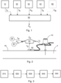
- Fig. 1 schematically shows a process model 50.
- the process model 50 is configured for determining, or in other words calculating, at least one calculated process parameter P C of a fluid F in a pipe 70 by using a determined fluid temperature T F , a determined reference temperature T R , a determined surface temperature T S and received nominal process parameters P N .
- the process model 50 gets the necessary input data from a plurality of entities connected with the process model 50. The input data is either measured, known, predetermined and/or preestimated.
- An invasive temperature sensor 10 provides the process model 50 with the fluid temperature T F .
- the fluid temperature T F that is measured by the invasive temperature sensor 10 relates to a temperature of the fluid F within the pipe 70, in particular a core temperature of the fluid F in the pipe 70.
- the invasive temperature sensor 10 comprises a probe that reaches into the pipe 70 in order to directly measure the fluid temperature T F .
- the reference temperature T R reflects the temperature outside of the pipe 70, in particular outside of an insulation of the pipe 70.
- a data interface 30 provides the process model 50 with at least one nominal process parameter P N .
- the at least one nominal process parameter P N reflects nominal properties of the process related to the fluid F in the pipe 70, or in other words, properties of the process that are known, predetermined and/or preestimated.
- the at least one nominal process parameter P N comprises at least one nominal pipe parameter, reflecting properties of the pipe 70 and at least one nominal fluid parameter, reflecting properties of the fluid F, wherein the at least one nominal pipe parameter comprises a geometry of the pipe 70 and/or a material of the pipe 70, wherein the at least one nominal fluid parameter comprises a nominal viscosity of the fluid F, a nominal heat conductivity of the fluid F, a nominal fluid pressure of the fluid F and/or a nominal fluid velocity of the fluid F.
- a non-invasive temperature sensor 40 also referred to as surface temperature sensor 40, provides the process model 50 with a surface temperature T S , being the temperature on the outer surface of the pipe 70.
- a non-invasive process parameter sensor 60 provides the process model 50 with at least one measured process parameter P M .
- the measured process parameter P M for example comprise a measured pressure P of the fluid F, a measured velocity of the fluid F, a measured viscosity of the fluid F and/or a measured heat conductivity of the fluid F.
- the process model 50 uses the at least one measured process parameter P M to further enhance the accuracy of the calculation of the calculated process parameter P C .
- Fig. 2 schematically shows a system for calculating at least one calculated process parameter P C of a fluid F in a pipe 70.
- a fluid F runs through a pipe 70.
- a process parameter for example the pressure P in the pipe 70 needs to be known.
- An invasive form of measuring the process parameter is not applicable in most situations, thus a calculation of the calculated process parameter P C is performed by the process model 50.
- the system comprises a surface temperature sensor 40 that is disposed at a pipe surface of the pipe 70.
- the surface temperature sensor 40 is able to directly determine a surface temperature T S , being the temperature of the outer surface of the pipe 70.
- the pipe 70 is surrounded by an insulation.
- the surface temperature T S relates to the temperature on the outside of the pipe 70 under the insulation.
- the system comprises a reference temperature sensor 20 that measures the reference temperature T R outside of the pipe 70, in particular outside of the insulation of the pipe 70.
- the system further comprises a data interface 30 that is configured for receiving nominal process parameters P N , wherein the nominal process parameters P N relate to nominal parameters of a process that relates to the fluid F in the pipe 70.
- the nominal process parameters P N comprise information about the fluid F and the pipe 70 that is known or can be estimated to sufficient accuracy due to the nature of the process.
- the system comprises a process model 50 that is configured to provide a calculation of the process parameter, referred to as calculated process parameter P C .
- the process model 50 uses different inputs in addition to the determined fluid temperature T F to perform an estimation algorithm that provides the calculated process parameter P C .
- the process model 50 uses the determined fluid temperature T F , the determined reference temperature T R , the determined surface temperature T S and the provided nominal process parameters P N .
- Fig. 3 schematically shows a method for determining at least one calculated process parameter P C of a fluid F in a pipe 70.
- a data interface 30 received nominal process parameters P N , wherein the nominal process parameters P N relate to nominal parameters P N of a process that relates to the fluid F in the pipe 70.
- an invasive temperature sensor 10 determined a fluid temperature T F of the fluid F in the pipe 70.
- a reference temperature sensor 20 disposed outside of the pipe 70, determines a reference temperature T R outside of the pipe 70.
- a surface temperature sensor 40 disposed at a surface of the pipe 70, determines a surface temperature T S of the pipe 70.
- a process model 50 determines at least one calculated process parameter P C of the fluid F in the pipe 70 by using the determined reference temperature T R , the determined surface temperature T S , the received nominal process parameters P N and the determined fluid temperature T F .
Landscapes
- Physics & Mathematics (AREA)
- General Physics & Mathematics (AREA)
- Fluid Mechanics (AREA)
- Spectroscopy & Molecular Physics (AREA)
- Measuring Temperature Or Quantity Of Heat (AREA)
- Pipeline Systems (AREA)
Abstract
a data interface (30), configured for receiving nominal process parameters (PN), wherein the nominal process parameters (PN) relate to nominal parameters of a process that relates to the fluid (F) in the pipe (70);
an invasive temperature sensor (10), configured for determining a fluid temperature (TF) of the fluid (F) in the pipe (70);
a reference temperature sensor (20) disposed outside of the pipe (70), configured for determining a reference temperature (TR) outside of the pipe (70);
a surface temperature sensor (40) disposed at a surface of the pipe (70), configured for determining a surface temperature (TS) of the pipe (70);
a process model (50), configured for determining at least one calculated process parameter (PC) of the fluid (F) in the pipe (70) by using the determined reference temperature (TR), the determined surface temperature (TS), the received nominal process parameters (PN) and the determined fluid temperature (TF).
Description
- The invention relates to a system and method for determining at least one calculated process parameter of a fluid in a pipe.
- Industrial process sensors like flow or pressure or viscosity sensors need traditionally invasive installations, needing direct access to the process fluid. In many cases, e.g. in case of explosive or toxic gases, the invasive access involving sealed joints in the piping represents a relevant safety risk (e.g. leakage due to corrosion, erosion or mechanical damage). Only temperature sensors have the potential for less critical installations by using thermowells which are welded into the pipe.
- These drawbacks could be avoided by non-invasive measurement of the pressure or of flow or other quantity of interest. For flow, e.g., non-invasive systems are commercially available (mainly ultrasonic systems), but rarely used due to their high cost and sensitivity to installation accuracy. For pressure no commercial non-invasive solution is available. Though many alternatives to measure the pressure through the pipe wall without drilling a hole have been described in the literature, none of the proposed solutions have ever been realized in products due to severe shortcomings and limitations. Especially the very small deformation of pressure piping (due to the pressure vessel design regulations) results in poor resolution and accuracy of non-invasive pressure sensing based on mechanical measurements, so these approaches are not competitive due to their unfavorable cost/performance ratio.
- It is therefore an objective of the invention to provide a system for calculating at least one calculated process parameter of a fluid in a pipe. This objective is achieved by the subject-matter of the independent claims. Further preferred embodiments are evident from the dependent patent claims.
- According to an aspect of the invention, a system for calculating at least one calculated process parameter of a fluid in a pipe, comprises the following: A data interface, configured for receiving nominal process parameters, wherein the nominal process parameters comprise pipe parameters and at least one fluid parameter, wherein the at least one pipe parameter comprises a geometry of the pipe and/or a material of the pipe, wherein the at least one fluid parameter comprises a nominal viscosity of the fluid, a nominal heat conductivity of the fluid, a nominal pressure of the fluid and/or a nominal velocity of the fluid. An invasive temperature sensor, configured for determining a fluid temperature of the fluid in the pipe. A reference temperature sensor disposed outside of the pipe, configured for determining a reference temperature outside of the pipe. A surface temperature sensor disposed on a surface of the pipe, configured for determining a surface temperature of the pipe. A process model, configured for determining at least one calculated process parameter of the fluid in the pipe by using the determined reference temperature, the determined surface temperature, the received process parameters and the determined fluid temperature.
- In other words, a process parameter, for example pressure or velocity of the fluid, can be determined in a non-invasive way. Non-invasive, as used herein, relates to a form of sensing, wherein no probe is inserted into the pipe. In this case, an invasive temperature sensor is used for the determination of the process parameter, however no invasive process parameter is used. This means that no additional invasive sensor is needed beyond an the existing invasive temperature sensor to gain information on process parameters like fluid pressure or fluid velocity. Non-invasive, as used herein, relates to a form of sensing, wherein no probe penetrates the pipe wall or protrudes into the flow of the fluid in the pipe.
- The term "nominal process parameter", as used herein, comprises information about the process that is performed using the fluid and the pipe that are known, for example by predetermination or preestimation. In other words, the nominal process parameters are provided to the system by a data interface so that the system, in particular the process model is provided with general information about the pipe, the fluid and the process carried out itself. The nominal process parameters are for example stored in a database and just read out by the system. Alternatively the nominal process parameters are read out from control system information from nearby sensors. Part of the nominal process parameters (e.g. fluid information) can also be provided as input values during device setup.
- The term "calculated process parameter", as used herein, relates to an estimation of the process parameter, for example fluid velocity or fluid pressure that is calculated by the process model. In other words, instead of directly measuring a process parameter with an invasive sensor, the process model provides a calculated process parameter that is more accurate than a measuring said process parameter with a non-invasive sensor.
- Preferably, the surface temperature sensor is a state-of-the-art clamp-on temperature sensor as described in Gebhardt, Jörg / Daake, Wilhelm / Ude, Peter / Schroder, Karsten / Sosale, Guruprasad: Accurate and quickly responsive surface temperature measurement: a step to widespread non-invasive T-measurement in industry, 2019, IEEE International Instrumentation and Measurement Technology Conference, I2MTC, Auckland, New Zealand, May 20-23, or by a standard cable (mineral insulated or not) thermometer, or by an IR temperature sensor.
- Preferably, the reference temperature relates to a temperature outside the pipe, in a certain distance of the pipe wall's outer surface. It can be either embedded in the insulation structure or can be outside of it. In the latter case it can be an ambient temperature.
- Preferably, the fluid temperature refers to the temperature of the fluid in the center of the pipe that has the largest distance to the pipe walls. For example, for a cylindrical pipe, the center of the pipe extend along the rotation axis of the pipe. In case of an invasive temperature sensor, the invasive temperature sensor extends a probe into the pipe to the center of the pipe to measure the fluid temperature. Consequently, the fluid temperature, provided by the invasive temperature sensor relates to a measured fluid temperature in the center of the pipe.
- The sensors, namely the reference temperature sensor, the surface temperature sensor and the invasive temperature sensor are connected to a common electronic unit within which the processing of the signals and the process model, carrying out the calculation of the calculated process parameter, are implemented.
- Preferably, the fluid is gas.
- Preferably, the fluid is a compressive fluid.
- In gas flow the temperature is not distributed uniformly across the pipe cross-section. The temperature profile, or the temperature difference between the core of the flow and the pipe surface depends on the heat conductivity of the system. The heat conductivity in the fluid depends on various flow parameters, of which pressure has a very large effect. For existing non-invasive temperature sensors, the pressure was found to be a major parameter to enable sufficient accuracy of the model calculation for the fluid temperature.
- Preferably, the process model performs its full calculation locally in the system. Alternatively, at least some of the calculations are performed in a cloud service. Furthermore, the process model further preferably uses parametric look-up tables that references predetermined inputs to predetermined outputs to reduce computational capacity requirements of the process model.
- Consequently, the system provides a means for non-invasively determining the pressure in fluid, in particular gas, filled pipes. Furthermore, the system can be applied to any pipe featuring at least one invasive temperature sensor, giving information on the fluid temperature at a known distance from the pipe wall. Such invasive temperature measurement points are often implemented with fully welded thermowells, representing a much smaller leakage risk than any pressure.
- In a preferred embodiment, the process model is configured for determining a Nußelt number of the fluid by using the fluid temperature and determining the at least one calculated process parameter by using the determined Nußelt number, wherein the Nußelt number depends on a Prandtl number of the fluid and a Reynolds number of the fluid, wherein the Prandtl number and the Reynolds number each depend on the at least one calculated process parameter.
- A thermal resistance of a fluid boundary layer, the layer between the fluid and the pipe wall, is particularly relevant for the difference of the pipe surface temperature and the fluid temperature. The boundary layer in a pipe flow is generally not rigorously defined regarding its geometric extension. Nevertheless, its thermal resistance (or inverse thermal conductivity) is usually defined as the thermal resistance connecting (or separating) the inner wall temperature and the average (bulk-) temperature of the medium flowing in the pipe.
- The thermal resistance depends on the fluid density, and therefore on pressure, and also on fluid velocity in the pipe.
- The thermal resistance of the fluid boundary layer in pipe hydrodynamics can be described by the Nußelt number, Nu. It is defined as the ratio of convective to pure conductive heat conductivity across the fluid boundary layer.
- Nu in many cases first depends on material data of the fluid, in particular on the Prandtl number, Pr, in particular in accordance with equation 1.

- The Prandtl number is the ratio of momentum to thermal diffusion constants. It is generally a function of temperature and pressure, but for pressure between 0.1 and 10 bars in gases it is determined just by the adiabatic (isentropic) exponent of the gas. For the fluids of interest, Pr can be determined as exactly as necessary in the form: Pr = Pr (T, P)
- The second ingredient for Nu is the Reynolds number, Re, in the situation of interest. Re is determined by material data of the fluid and process parameters as outlined in equation 2:

- As Re depends on the fluid density p, it therefore depends on pressure P in case of gases. η also may be pressure dependent. In a similar manner, for a given pressure, the density of the fluid remains relatively constant but flow changes have an effect.
- In total Nu is defined as outlined in equation 3:

- Therefore, knowledge of fluid pressure P and/or fluid velocity v will help to increase the estimation accuracy for Re, for Pr, and for Nu.
- As described in detail in
EP 3537124 B1 : For the process temperature Tm the abovementioned considerations lead to a formula where Tm is a function of at least the following variables:
- Here, Rbl is the inverse conductivity (with units: m2 K / W) of the medium boundary layer adjacent to the inner pipe wall surface.
- Rw is the inverse conductivity of the pipe wall, including possible coatings inside and outside, with thicknesses dw i, and thermal conductivities "λw i of the materials.
- RF is the inverse conductivity of the insulation layers, if any, and of outside convective boundary layers. If there is no insulation, the corresponding contribution to inverse conductivity is zero.
- Whereas in
EP 3537124 B1 the setup and model is used to determine Tm, a setup is disclosed where Tm is measured invasively, in order to determine one of the other variables in Equation 4. - According to the invention, if all but one of the independent variables on the right side of Equation 4 are known or can be estimated (this would be the parameters PN) , the one remaining unknown variable (PC) can be calculated by inverting the expression in Equation 4. This is possible, at least locally in the space of independent variables, under very general regularity conditions according to the implicit function theorem, well known from classical analysis (e.g. A.N. Kolmogorov, S.V. Fomin, "Elements of the theory of functions and functional analysis", Vol.s 1-2 , Martino Fine Books (2012).
- The invention also is to be understood to include cases when there are more influence factors than explicitly shown in Equation 4 (e.g. in complex flow situations where entry length L and roughness or friction factors (see
EP 3537124 B1 ) of the pipe or other variables may play a role). The basic procedure and learning, then, remains the same. - In the system as described in
EP 3537124 B1 , a measured value for P and/or v, or some other estimate of P and/or v can be used for a subsequent calculation of the three dimensionless variables, leading to the determination of the accurate estimation of the fluid temperature. - Therefore, according to the present invention, by inverting the original calculation model for the temperature difference between the fluid velocity and the pipe surface or the reference temperature, the knowledge of both temperatures can help to quantify the value of at least one of the process parameters in Equation 4 and in subsequent sections, in particular, either the fluid pressure or of the fluid velocity.
- The concept can be extended also to the measurement of the pressure in fluid tanks or vessels equipped with at least one invasive temperature measurement point.
- In a preferred embodiment, the nominal process parameters comprise at least one pipe parameter and at least one fluid parameter, wherein the at least one pipe parameter comprises a geometry of the pipe and/or a material of the pipe, wherein the at least one fluid parameter comprises a nominal viscosity of the fluid, a nominal heat conductivity of the fluid, a nominal pressure of the fluid and/or a nominal velocity of the fluid.
- In a preferred embodiment, the at least one calculated process parameter comprises a calculated pressure of the fluid, a calculated velocity of the fluid, a calculated viscosity of the fluid and/or a calculated heat conductivity of the fluid or any of the quantities mentioned in Equation 4 and subsequent sections.
- Due to the relationship between the different process parameters and the fluid temperature, calculations or statements about fluid pressure, fluid velocity, fluid viscosity and/or fluid heat conductivity can be made by the process model.
- In a preferred embodiment, the system comprises a process parameter sensor, configured for determining at least one measured process parameter. The process model is configured for determining the at least one calculated process parameter by using the at least one measured process parameter.
- Due to the relationship between the different process parameters and the fluid temperature, each additional information about the process can be used to further improve the accuracy of the calculation. In other words, when calculating a calculated process parameter, measurements of other process parameters can enhance the accuracy of the calculation. For example, when the process model calculates a pressure of the fluid, the accuracy of the calculation can be enhanced by a measurement of the velocity of the fluid, in particular by a non-invasive velocity sensor. The more additional process parameters are measured, the higher is the accuracy of the calculation of the calculated process parameter.
- In a preferred embodiment, the at least one measured process parameter comprises a measured pressure of the fluid, a measured velocity of the fluid, a measured viscosity of the fluid and/or a measured heat conductivity of the fluid.
- In a preferred embodiment, the process parameter sensor comprises a non-invasive process parameter sensor.
- Non-invasive process parameter sensors can be applied to the system, in particular to the pipe more easily and more secure than invasive process parameter sensors. Although the accuracy of the non-invasive process parameter sensors is usually worse than the accuracy of invasive process parameter sensors, each additional information for the process model enhances the calculation accuracy of the process model.
- In a preferred embodiment, the non-invasive process parameter sensor comprises a non-invasive velocity sensor, which is configured for determining the measured velocity of the fluid in a non-invasive way.
- Preferably, the non-invasive velocity sensor is an ultrasonic sensor that is configured for determining the fluid velocity in a non-invasive way. Further preferably, the process model uses said determined fluid velocity to calculate a calculated fluid pressure.
- In a preferred embodiment, the non-invasive process parameter sensor is integrated into the surface temperature sensor.
- In a preferred embodiment, the surface temperature sensor comprises a clamping system that is configured for attaching the surface temperature sensor on a surface of the pipe. The non-invasive process parameter sensor can be, e.g., a non-invasive pressure sensor that is integrated into the clamping system.
- In this example, the calculated process parameter is preferably the fluid velocity. The fluid velocity shares a strong physical relationship with the pressure in the pipe and the fluid temperature as well as the surface temperature. Consequently, the non-invasive pressure sensor that is integrated into the surface temperature sensor provides a measured pressure of the fluid to the process model in order to calculate the calculated fluid velocity. Thus, the additional non-invasive process parameter sensor is attached to the pipe together with the surface temperature sensor, allowing a simple addition of the non-invasive process parameter sensor to the pipe.
- In a preferred embodiment, the non-invasive process parameter sensor comprises a non-invasive pressure sensor that is integrated into the clamping system by a strain gauge on a clamp strip, a tensile force sensor in the clamp or a compressive force sensor between the clamp and the pipe surface.
- According to an aspect of the invention, a method for calculating calculated process parameters of a fluid in a pipe comprises the following steps. Receiving, by a data interface, nominal process parameters, wherein the nominal process parameters comprise pipe parameters and at least one fluid parameter, wherein the at least one pipe parameter comprises a geometry of the pipe and/or a material of the pipe, wherein the at least one fluid parameter comprises a nominal viscosity of the fluid, a nominal heat conductivity of the fluid, a nominal pressure of the fluid and/or a nominal velocity of the fluid. Determining, by an invasive temperature sensor, a fluid temperature of the fluid in the pipe. Determining, by a surface temperature sensor disposed on a surface of the pipe, the surface temperature of the pipe. Determining, by a reference temperature sensor disposed outside of the pipe a reference temperature outside of the pipe. Determining, by a process model, at least one calculated process parameter of the fluid in the pipe by using the determined reference temperature, the determined surface temperature, the received process parameters and the determined fluid temperature.
- According to an aspect of the invention, a computer program comprises instructions, which, when the program is executed by a computer, cause the computer to carry out the steps of a method, as described herein.
- According to an aspect of the invention, a computer-readable medium comprises instructions which, when executed by a computer, cause the computer to carry out the steps of a method, as described herein.
- The subject matter of the invention will be explained in more detail in the following text with reference to preferred exemplary embodiments which are illustrated in the attached drawings, in which:
-
Fig. 1 schematically shows a process model for determining at least one calculated process parameter; -
Fig. 2 schematically shows a system for calculating at least one calculated process parameter of a fluid in a pipe; and -
Fig. 3 schematically shows a method for calculating at least one calculated process parameter of a fluid in a pipe. - The reference symbols used in the drawings, and their meanings, are listed in summary form in the list of reference symbols. In principle, identical parts are provided with the same reference symbols in the figures.
-
Fig. 1 schematically shows aprocess model 50. Theprocess model 50 is configured for determining, or in other words calculating, at least one calculated process parameter PC of a fluid F in apipe 70 by using a determined fluid temperature TF, a determined reference temperature TR, a determined surface temperature TS and received nominal process parameters PN. Theprocess model 50 gets the necessary input data from a plurality of entities connected with theprocess model 50. The input data is either measured, known, predetermined and/or preestimated. - An
invasive temperature sensor 10 provides theprocess model 50 with the fluid temperature TF. The fluid temperature TF that is measured by theinvasive temperature sensor 10 relates to a temperature of the fluid F within thepipe 70, in particular a core temperature of the fluid F in thepipe 70. Theinvasive temperature sensor 10 comprises a probe that reaches into thepipe 70 in order to directly measure the fluid temperature TF. The reference temperature TR reflects the temperature outside of thepipe 70, in particular outside of an insulation of thepipe 70. Adata interface 30 provides theprocess model 50 with at least one nominal process parameter PN. The at least one nominal process parameter PN reflects nominal properties of the process related to the fluid F in thepipe 70, or in other words, properties of the process that are known, predetermined and/or preestimated. The at least one nominal process parameter PN comprises at least one nominal pipe parameter, reflecting properties of thepipe 70 and at least one nominal fluid parameter, reflecting properties of the fluid F, wherein the at least one nominal pipe parameter comprises a geometry of thepipe 70 and/or a material of thepipe 70, wherein the at least one nominal fluid parameter comprises a nominal viscosity of the fluid F, a nominal heat conductivity of the fluid F, a nominal fluid pressure of the fluid F and/or a nominal fluid velocity of the fluid F. Anon-invasive temperature sensor 40, also referred to assurface temperature sensor 40, provides theprocess model 50 with a surface temperature TS, being the temperature on the outer surface of thepipe 70. - Optionally, a non-invasive
process parameter sensor 60 provides theprocess model 50 with at least one measured process parameter PM. The measured process parameter PM for example comprise a measured pressure P of the fluid F, a measured velocity of the fluid F, a measured viscosity of the fluid F and/or a measured heat conductivity of the fluid F. In other words, theprocess model 50 uses the at least one measured process parameter PM to further enhance the accuracy of the calculation of the calculated process parameter PC. -
Fig. 2 schematically shows a system for calculating at least one calculated process parameter PC of a fluid F in apipe 70. During a production process, a fluid F runs through apipe 70. For analysis and/or monitoring reasons, a process parameter, for example the pressure P in thepipe 70 needs to be known. An invasive form of measuring the process parameter is not applicable in most situations, thus a calculation of the calculated process parameter PC is performed by theprocess model 50. For non-invasive temperature measurement, the system comprises asurface temperature sensor 40 that is disposed at a pipe surface of thepipe 70. Thesurface temperature sensor 40 is able to directly determine a surface temperature TS, being the temperature of the outer surface of thepipe 70. In general, thepipe 70 is surrounded by an insulation. Consequently, the surface temperature TS relates to the temperature on the outside of thepipe 70 under the insulation. In addition, the system comprises areference temperature sensor 20 that measures the reference temperature TR outside of thepipe 70, in particular outside of the insulation of thepipe 70. The system further comprises adata interface 30 that is configured for receiving nominal process parameters PN, wherein the nominal process parameters PN relate to nominal parameters of a process that relates to the fluid F in thepipe 70. In other words, the nominal process parameters PN comprise information about the fluid F and thepipe 70 that is known or can be estimated to sufficient accuracy due to the nature of the process. - In order to calculate the at least one calculated process parameter PC, which as described is not directly measured by a sensor, the system comprises a
process model 50 that is configured to provide a calculation of the process parameter, referred to as calculated process parameter PC. Theprocess model 50 uses different inputs in addition to the determined fluid temperature TF to perform an estimation algorithm that provides the calculated process parameter PC. In this case, theprocess model 50 uses the determined fluid temperature TF, the determined reference temperature TR, the determined surface temperature TS and the provided nominal process parameters PN. -
Fig. 3 schematically shows a method for determining at least one calculated process parameter PC of a fluid F in apipe 70. - In a first step S10 a
data interface 30 received nominal process parameters PN, wherein the nominal process parameters PN relate to nominal parameters PN of a process that relates to the fluid F in thepipe 70. In another step S20, aninvasive temperature sensor 10 determined a fluid temperature TF of the fluid F in thepipe 70. In another step S30, areference temperature sensor 20 disposed outside of thepipe 70, determines a reference temperature TR outside of thepipe 70. In another step S40, asurface temperature sensor 40 disposed at a surface of thepipe 70, determines a surface temperature TS of thepipe 70. In another step S50, aprocess model 50 determines at least one calculated process parameter PC of the fluid F in thepipe 70 by using the determined reference temperature TR, the determined surface temperature TS, the received nominal process parameters PN and the determined fluid temperature TF. -
- 10
- invasive temperature sensor
- 20
- reference temperature sensor
- 30
- data interface
- 40
- surface temperature sensor
- 50
- process model
- 60
- process parameter sensor
- 70
- pipe
- F
- fluid
- PN
- nominal process parameter
- TF
- fluid temperature
- TR
- reference temperature
- TS
- surface temperature
- PC
- calculated process parameter
- PM
- measured process parameter
- S10
- receiving nominal process parameters
- S20
- determining a fluid temperature
- S30
- determining a reference temperature
- S40
- determining a surface temperature
- S50
- determining at least one calculated process parameter
Claims (14)
- System for determining at least one calculated process parameter (PC) of a fluid (F) in a pipe (70), comprising:a data interface (30), configured for receiving nominal process parameters (PN), wherein the nominal process parameters (PN) relate to nominal parameters of a process that relates to the fluid (F) in the pipe (70);an invasive temperature sensor (10), configured for determining a fluid temperature (TF) of the fluid (F) in the pipe (70);a reference temperature sensor (20) disposed outside of the pipe (70), configured for determining a reference temperature (TR) outside of the pipe (70);a surface temperature sensor (40) disposed at a surface of the pipe (70), configured for determining a surface temperature (TS) of the pipe (70);a process model (50), configured for determining at least one calculated process parameter (PC) of the fluid (F) in the pipe (70) by using the determined reference temperature (TR), the determined surface temperature (TS), the received nominal process parameters (PN) and the determined fluid temperature (TF).
- System of claim 1, wherein the process model (50) is configured fordetermining a Nußelt number of the fluid by using the fluid temperature (TF);determining the at least one calculated process parameter (PC) by using the determined Nußelt number, wherein the Nußelt number depends on a Prandtl number of the fluid (F) and a Reynolds number of the fluid (F), wherein the Prandtl number and the Reynolds number each depend on the at least one calculated process parameter (PC).
- System of any of the preceding claims,
wherein the nominal process parameters (PN) comprise at least one pipe parameter and at least one fluid parameter, wherein the at least one pipe parameter comprises a geometry of the pipe (70) and/or a material of the pipe (70), wherein the at least one fluid parameter comprises a nominal viscosity of the fluid (F), a nominal heat conductivity of the fluid (F), a nominal pressure of the fluid (F) and/or a nominal velocity of the fluid (F). - System of any of the preceding claims,
wherein the at least one calculated process parameter (PC) comprises a calculated pressure of the fluid, a calculated velocity of the fluid, a calculated viscosity of the fluid and/or a calculated heat conductivity of the fluid. - System of any of the preceding claims, comprising:a process parameter sensor (60), configured for determining at least one measured process parameter (PM);wherein the process model (50) is configured for determining the at least one calculated process parameter (PC) by using the at least one measured process parameter (PM).
- System of any of the preceding claims,
wherein the at least one measured process parameter (PM) comprises a measured pressure of the fluid (F), a measured velocity of the fluid (F), a measured viscosity of the fluid (F) and/or a measured heat conductivity of the fluid (F). - System of any of claims 6-7,
wherein the process parameter sensor (60) comprises a non-invasive process parameter sensor. - System of claim 7,
wherein the non-invasive process parameter sensor comprises a non-invasive velocity sensor, which is configured for determining the measured velocity of the fluid (F) in a non-invasive way. - System of claim 7,
wherein the non-invasive process parameter sensor is integrated into the surface temperature sensor (40). - System of any of the claims 2-9,wherein the surface temperature sensor (40) comprises a clamping system that is configured for attaching the surface temperature sensor (TS) on a surface of the pipe (70);wherein the non-invasive process parameter sensor is a non-invasive pressure sensor that is integrated into the clamping system.
- System of claim 10,
wherein the non-invasive process parameter sensor comprises a non-invasive pressure sensor that is integrated into the clamping system by a strain gauge on a clamp strip, a tensile force sensor in the clamp or a compressive force sensor between the clamp and the pipe surface. - Method for determining a calculated process parameters (PC) of a fluid (F) in a pipe (P), comprising:receiving (S10), by a data interface (30), nominal process parameters (PN), wherein the nominal process parameters (PN) relate to nominal parameters (PN) of a process that relates to the fluid (F) in the pipe (70);determining (S20), by an invasive temperature sensor (10), a fluid temperature (TF) of the fluid (F) in the pipe (70);determining (S30), by a reference temperature sensor (20) disposed outside of the pipe (70), a reference temperature (TR) outside of the pipe (70);determining (S40), by a surface temperature sensor (40) disposed at a surface of the pipe (70), a surface temperature (TS) of the pipe (70);determining (S50), by a process model (50), at least one calculated process parameter (PC) of the fluid (F) in the pipe (70) by using the determined reference temperature (TR), the determined surface temperature (TS), the received nominal process parameters (PN) and the determined fluid temperature (TF).
- A computer program comprising instructions, which, when the program is executed by a computer, cause the computer to carry out the steps of a method according to any of claim 12.
- A computer-readable medium comprising instructions which, when executed by a computer, cause the computer to carry out the steps of a method according to claim 12.
Priority Applications (3)
| Application Number | Priority Date | Filing Date | Title |
|---|---|---|---|
| EP22172013.9A EP4273514B1 (en) | 2022-05-06 | 2022-05-06 | System and method for determining at least one calculated process parameter of a fluid in a pipe |
| US18/312,909 US12422290B2 (en) | 2022-05-06 | 2023-05-05 | System and method for determining at least one calculated process parameter of a fluid in a pipe |
| CN202310497402.6A CN117007107A (en) | 2022-05-06 | 2023-05-05 | Systems and methods for determining at least one calculated process parameter for fluid in a pipeline |
Applications Claiming Priority (1)
| Application Number | Priority Date | Filing Date | Title |
|---|---|---|---|
| EP22172013.9A EP4273514B1 (en) | 2022-05-06 | 2022-05-06 | System and method for determining at least one calculated process parameter of a fluid in a pipe |
Publications (2)
| Publication Number | Publication Date |
|---|---|
| EP4273514A1 true EP4273514A1 (en) | 2023-11-08 |
| EP4273514B1 EP4273514B1 (en) | 2024-09-18 |
Family
ID=81585517
Family Applications (1)
| Application Number | Title | Priority Date | Filing Date |
|---|---|---|---|
| EP22172013.9A Active EP4273514B1 (en) | 2022-05-06 | 2022-05-06 | System and method for determining at least one calculated process parameter of a fluid in a pipe |
Country Status (3)
| Country | Link |
|---|---|
| US (1) | US12422290B2 (en) |
| EP (1) | EP4273514B1 (en) |
| CN (1) | CN117007107A (en) |
Families Citing this family (1)
| Publication number | Priority date | Publication date | Assignee | Title |
|---|---|---|---|---|
| EP4273524A1 (en) * | 2022-05-06 | 2023-11-08 | Abb Schweiz Ag | System and method for non-invasive determining of a fluid temperature |
Citations (3)
| Publication number | Priority date | Publication date | Assignee | Title |
|---|---|---|---|---|
| EP1014061A1 (en) * | 1998-12-21 | 2000-06-28 | Ruhrgas Aktiengesellschaft | Method for determining the gas temperature, averaged over the cross-section of a gas conduit |
| DE102016101862A1 (en) * | 2016-02-03 | 2017-08-03 | Dr. Ing. H.C. F. Porsche Aktiengesellschaft | Method for determining a temperature, system for determining a temperature and using a system for determining a temperature |
| EP3537124A1 (en) | 2018-03-08 | 2019-09-11 | ABB Schweiz AG | Method for non-intrusive determining of a temperature of a fluid flowing through a conduit section |
Family Cites Families (14)
| Publication number | Priority date | Publication date | Assignee | Title |
|---|---|---|---|---|
| GB9210212D0 (en) * | 1992-05-12 | 1992-06-24 | Schlumberger Ltd | Multiphase fluid flow measurement |
| FR2728968B1 (en) | 1994-12-30 | 1997-03-28 | Gaz De France | METHOD AND DEVICE FOR NON-INTRUSIVE MEASUREMENT OF FLUID PRESSURE FLUCTUATIONS WITHIN A PIPELINE |
| US7093496B2 (en) | 2004-03-31 | 2006-08-22 | Deere & Company | Non-intrusive pressure sensing device |
| GB2454220B (en) | 2007-11-01 | 2012-05-23 | Schlumberger Holdings | Apparatus and methods for detecting strain in structures |
| WO2013075111A1 (en) * | 2011-11-17 | 2013-05-23 | Utah State University | Thermal pulse flow meter |
| US20140251020A1 (en) | 2013-03-05 | 2014-09-11 | Ge-Hitachi Nuclear Energy Americas Llc | Method and apparatus for pipe pressure measurements |
| US10254179B2 (en) * | 2014-12-25 | 2019-04-09 | Fujitsu Limited | Enclosure surface temperature estimation method and electronic apparatus |
| GB2538805B (en) * | 2015-05-29 | 2018-06-27 | Gm Flow Measurement Services Ltd | Improved flow measurement apparatus and method of use |
| DE102015109450A1 (en) | 2015-06-12 | 2016-12-15 | Abb Schweiz Ag | Device for measuring the pressure of a fluid flowing through a pipeline |
| GB2543060A (en) | 2015-10-06 | 2017-04-12 | Atmos Wave Ltd | Sensing pressure variations in pipelines |
| DE102015121425A1 (en) | 2015-12-09 | 2017-06-14 | Abb Schweiz Ag | Device for non-intrusive measurement of the pressure of a fluid |
| KR20180096442A (en) * | 2017-02-21 | 2018-08-29 | 삼성전기주식회사 | Apparatus and method for measuring water temperature in pipes |
| ES2724775A1 (en) | 2018-03-08 | 2019-09-16 | Innomerics S L | Non-invasive external system for the determination of instantaneous pressure inside pipes and vessels, cylindrical circular section (Machine-translation by Google Translate, not legally binding) |
| US11209296B2 (en) | 2018-09-28 | 2021-12-28 | Rosemount Inc. | Non-intrusive process fluid pressure measurement system |
-
2022
- 2022-05-06 EP EP22172013.9A patent/EP4273514B1/en active Active
-
2023
- 2023-05-05 US US18/312,909 patent/US12422290B2/en active Active
- 2023-05-05 CN CN202310497402.6A patent/CN117007107A/en active Pending
Patent Citations (4)
| Publication number | Priority date | Publication date | Assignee | Title |
|---|---|---|---|---|
| EP1014061A1 (en) * | 1998-12-21 | 2000-06-28 | Ruhrgas Aktiengesellschaft | Method for determining the gas temperature, averaged over the cross-section of a gas conduit |
| DE102016101862A1 (en) * | 2016-02-03 | 2017-08-03 | Dr. Ing. H.C. F. Porsche Aktiengesellschaft | Method for determining a temperature, system for determining a temperature and using a system for determining a temperature |
| EP3537124A1 (en) | 2018-03-08 | 2019-09-11 | ABB Schweiz AG | Method for non-intrusive determining of a temperature of a fluid flowing through a conduit section |
| EP3537124B1 (en) | 2018-03-08 | 2021-01-27 | ABB Schweiz AG | Method and system for non-intrusive determining of a temperature of a fluid flowing through a conduit section |
Also Published As
| Publication number | Publication date |
|---|---|
| EP4273514B1 (en) | 2024-09-18 |
| US12422290B2 (en) | 2025-09-23 |
| US20230358585A1 (en) | 2023-11-09 |
| CN117007107A (en) | 2023-11-07 |
Similar Documents
| Publication | Publication Date | Title |
|---|---|---|
| US11852517B2 (en) | Method for generating a diagnostic from a deviation of a flow meter parameter | |
| WO1993004343A1 (en) | Nonintrusive flow sensing system | |
| CN101398322A (en) | Thermal flow measurement system and method | |
| EP4009022B1 (en) | Method, device and computer program for validating an invasive temperature measurement system | |
| US20260022980A1 (en) | Method and system for determining the temperature of a fluid flowing through a line body | |
| EP4273514B1 (en) | System and method for determining at least one calculated process parameter of a fluid in a pipe | |
| US8583397B2 (en) | Device for determination of thermal exchange coefficient and associated method | |
| EP0617271B1 (en) | Method for simultaneous determination of thermal conductivity and kinematic viscosity | |
| CN111521633A (en) | Device and method for identifying gas-liquid multiphase flow pattern based on thermal diffusion principle | |
| Gebhardt et al. | Accurate and quickly responsive surface temperature measurement: a step to widespread non-invasive T-measurement in industry | |
| JP2008107327A (en) | Pipe thickness measuring device and method | |
| EP4273524A1 (en) | System and method for non-invasive determining of a fluid temperature | |
| US20240077365A1 (en) | Temperature Measurement Facility | |
| Huster et al. | Experimental determination of the recovery factor on cylindrically flow-around temperature sensors Part 1: determination of the recovery factor for different Reynolds-and Mach-Numbers | |
| EP4350309B1 (en) | Computer implemented method for determining boundary thermal resistance data, a computer product element and a system | |
| EP4350310A1 (en) | Computer implemented method for determining boundary thermal resistance data, a computer product element and a system | |
| EP3583393B1 (en) | Calorimetric probe and a method for calorimetric measurement | |
| JPS59128429A (en) | Life monitoring method for pressure resisting parts | |
| Souza et al. | Displacer-Type Liquid Level Sensor with Liquid Density Auto-Compensation | |
| Klason et al. | Temperature measurement in flow pipes: Comparison with single Pt-100 and multisensors | |
| Smits | Preston probe calibrations at high Reynolds number | |
| JPS6118967B2 (en) |
Legal Events
| Date | Code | Title | Description |
|---|---|---|---|
| PUAI | Public reference made under article 153(3) epc to a published international application that has entered the european phase |
Free format text: ORIGINAL CODE: 0009012 |
|
| STAA | Information on the status of an ep patent application or granted ep patent |
Free format text: STATUS: THE APPLICATION HAS BEEN PUBLISHED |
|
| AK | Designated contracting states |
Kind code of ref document: A1 Designated state(s): AL AT BE BG CH CY CZ DE DK EE ES FI FR GB GR HR HU IE IS IT LI LT LU LV MC MK MT NL NO PL PT RO RS SE SI SK SM TR |
|
| STAA | Information on the status of an ep patent application or granted ep patent |
Free format text: STATUS: REQUEST FOR EXAMINATION WAS MADE |
|
| GRAP | Despatch of communication of intention to grant a patent |
Free format text: ORIGINAL CODE: EPIDOSNIGR1 |
|
| STAA | Information on the status of an ep patent application or granted ep patent |
Free format text: STATUS: GRANT OF PATENT IS INTENDED |
|
| 17P | Request for examination filed |
Effective date: 20240408 |
|
| RBV | Designated contracting states (corrected) |
Designated state(s): AL AT BE BG CH CY CZ DE DK EE ES FI FR GB GR HR HU IE IS IT LI LT LU LV MC MK MT NL NO PL PT RO RS SE SI SK SM TR |
|
| INTG | Intention to grant announced |
Effective date: 20240507 |
|
| RIC1 | Information provided on ipc code assigned before grant |
Ipc: G01F 1/684 20060101ALI20240423BHEP Ipc: G01K 1/143 20210101ALI20240423BHEP Ipc: G01K 13/024 20210101ALI20240423BHEP Ipc: G01K 13/02 20210101ALI20240423BHEP Ipc: G01F 1/68 20060101AFI20240423BHEP |
|
| GRAS | Grant fee paid |
Free format text: ORIGINAL CODE: EPIDOSNIGR3 |
|
| GRAA | (expected) grant |
Free format text: ORIGINAL CODE: 0009210 |
|
| STAA | Information on the status of an ep patent application or granted ep patent |
Free format text: STATUS: THE PATENT HAS BEEN GRANTED |
|
| AK | Designated contracting states |
Kind code of ref document: B1 Designated state(s): AL AT BE BG CH CY CZ DE DK EE ES FI FR GB GR HR HU IE IS IT LI LT LU LV MC MK MT NL NO PL PT RO RS SE SI SK SM TR |
|
| REG | Reference to a national code |
Ref country code: GB Ref legal event code: FG4D |
|
| REG | Reference to a national code |
Ref country code: CH Ref legal event code: EP |
|
| REG | Reference to a national code |
Ref country code: DE Ref legal event code: R096 Ref document number: 602022006133 Country of ref document: DE |
|
| REG | Reference to a national code |
Ref country code: IE Ref legal event code: FG4D |
|
| REG | Reference to a national code |
Ref country code: LT Ref legal event code: MG9D |
|
| PG25 | Lapsed in a contracting state [announced via postgrant information from national office to epo] |
Ref country code: NO Free format text: LAPSE BECAUSE OF FAILURE TO SUBMIT A TRANSLATION OF THE DESCRIPTION OR TO PAY THE FEE WITHIN THE PRESCRIBED TIME-LIMIT Effective date: 20241218 |
|
| PG25 | Lapsed in a contracting state [announced via postgrant information from national office to epo] |
Ref country code: GR Free format text: LAPSE BECAUSE OF FAILURE TO SUBMIT A TRANSLATION OF THE DESCRIPTION OR TO PAY THE FEE WITHIN THE PRESCRIBED TIME-LIMIT Effective date: 20241219 Ref country code: FI Free format text: LAPSE BECAUSE OF FAILURE TO SUBMIT A TRANSLATION OF THE DESCRIPTION OR TO PAY THE FEE WITHIN THE PRESCRIBED TIME-LIMIT Effective date: 20240918 |
|
| PG25 | Lapsed in a contracting state [announced via postgrant information from national office to epo] |
Ref country code: BG Free format text: LAPSE BECAUSE OF FAILURE TO SUBMIT A TRANSLATION OF THE DESCRIPTION OR TO PAY THE FEE WITHIN THE PRESCRIBED TIME-LIMIT Effective date: 20240918 |
|
| PG25 | Lapsed in a contracting state [announced via postgrant information from national office to epo] |
Ref country code: LV Free format text: LAPSE BECAUSE OF FAILURE TO SUBMIT A TRANSLATION OF THE DESCRIPTION OR TO PAY THE FEE WITHIN THE PRESCRIBED TIME-LIMIT Effective date: 20240918 |
|
| PG25 | Lapsed in a contracting state [announced via postgrant information from national office to epo] |
Ref country code: HR Free format text: LAPSE BECAUSE OF FAILURE TO SUBMIT A TRANSLATION OF THE DESCRIPTION OR TO PAY THE FEE WITHIN THE PRESCRIBED TIME-LIMIT Effective date: 20240918 |
|
| REG | Reference to a national code |
Ref country code: NL Ref legal event code: MP Effective date: 20240918 |
|
| PG25 | Lapsed in a contracting state [announced via postgrant information from national office to epo] |
Ref country code: RS Free format text: LAPSE BECAUSE OF FAILURE TO SUBMIT A TRANSLATION OF THE DESCRIPTION OR TO PAY THE FEE WITHIN THE PRESCRIBED TIME-LIMIT Effective date: 20241218 |
|
| PG25 | Lapsed in a contracting state [announced via postgrant information from national office to epo] |
Ref country code: RS Free format text: LAPSE BECAUSE OF FAILURE TO SUBMIT A TRANSLATION OF THE DESCRIPTION OR TO PAY THE FEE WITHIN THE PRESCRIBED TIME-LIMIT Effective date: 20241218 Ref country code: NO Free format text: LAPSE BECAUSE OF FAILURE TO SUBMIT A TRANSLATION OF THE DESCRIPTION OR TO PAY THE FEE WITHIN THE PRESCRIBED TIME-LIMIT Effective date: 20241218 Ref country code: LV Free format text: LAPSE BECAUSE OF FAILURE TO SUBMIT A TRANSLATION OF THE DESCRIPTION OR TO PAY THE FEE WITHIN THE PRESCRIBED TIME-LIMIT Effective date: 20240918 Ref country code: HR Free format text: LAPSE BECAUSE OF FAILURE TO SUBMIT A TRANSLATION OF THE DESCRIPTION OR TO PAY THE FEE WITHIN THE PRESCRIBED TIME-LIMIT Effective date: 20240918 Ref country code: GR Free format text: LAPSE BECAUSE OF FAILURE TO SUBMIT A TRANSLATION OF THE DESCRIPTION OR TO PAY THE FEE WITHIN THE PRESCRIBED TIME-LIMIT Effective date: 20241219 Ref country code: FI Free format text: LAPSE BECAUSE OF FAILURE TO SUBMIT A TRANSLATION OF THE DESCRIPTION OR TO PAY THE FEE WITHIN THE PRESCRIBED TIME-LIMIT Effective date: 20240918 Ref country code: BG Free format text: LAPSE BECAUSE OF FAILURE TO SUBMIT A TRANSLATION OF THE DESCRIPTION OR TO PAY THE FEE WITHIN THE PRESCRIBED TIME-LIMIT Effective date: 20240918 |
|
| REG | Reference to a national code |
Ref country code: AT Ref legal event code: MK05 Ref document number: 1725059 Country of ref document: AT Kind code of ref document: T Effective date: 20240918 |
|
| PG25 | Lapsed in a contracting state [announced via postgrant information from national office to epo] |
Ref country code: NL Free format text: LAPSE BECAUSE OF FAILURE TO SUBMIT A TRANSLATION OF THE DESCRIPTION OR TO PAY THE FEE WITHIN THE PRESCRIBED TIME-LIMIT Effective date: 20240918 |
|
| PG25 | Lapsed in a contracting state [announced via postgrant information from national office to epo] |
Ref country code: PT Free format text: LAPSE BECAUSE OF FAILURE TO SUBMIT A TRANSLATION OF THE DESCRIPTION OR TO PAY THE FEE WITHIN THE PRESCRIBED TIME-LIMIT Effective date: 20250120 Ref country code: IS Free format text: LAPSE BECAUSE OF FAILURE TO SUBMIT A TRANSLATION OF THE DESCRIPTION OR TO PAY THE FEE WITHIN THE PRESCRIBED TIME-LIMIT Effective date: 20250118 |
|
| PG25 | Lapsed in a contracting state [announced via postgrant information from national office to epo] |
Ref country code: RO Free format text: LAPSE BECAUSE OF FAILURE TO SUBMIT A TRANSLATION OF THE DESCRIPTION OR TO PAY THE FEE WITHIN THE PRESCRIBED TIME-LIMIT Effective date: 20240918 Ref country code: SM Free format text: LAPSE BECAUSE OF FAILURE TO SUBMIT A TRANSLATION OF THE DESCRIPTION OR TO PAY THE FEE WITHIN THE PRESCRIBED TIME-LIMIT Effective date: 20240918 |
|
| PG25 | Lapsed in a contracting state [announced via postgrant information from national office to epo] |
Ref country code: ES Free format text: LAPSE BECAUSE OF FAILURE TO SUBMIT A TRANSLATION OF THE DESCRIPTION OR TO PAY THE FEE WITHIN THE PRESCRIBED TIME-LIMIT Effective date: 20240918 |
|
| PG25 | Lapsed in a contracting state [announced via postgrant information from national office to epo] |
Ref country code: EE Free format text: LAPSE BECAUSE OF FAILURE TO SUBMIT A TRANSLATION OF THE DESCRIPTION OR TO PAY THE FEE WITHIN THE PRESCRIBED TIME-LIMIT Effective date: 20240918 Ref country code: AT Free format text: LAPSE BECAUSE OF FAILURE TO SUBMIT A TRANSLATION OF THE DESCRIPTION OR TO PAY THE FEE WITHIN THE PRESCRIBED TIME-LIMIT Effective date: 20240918 |
|
| PG25 | Lapsed in a contracting state [announced via postgrant information from national office to epo] |
Ref country code: CZ Free format text: LAPSE BECAUSE OF FAILURE TO SUBMIT A TRANSLATION OF THE DESCRIPTION OR TO PAY THE FEE WITHIN THE PRESCRIBED TIME-LIMIT Effective date: 20240918 Ref country code: PL Free format text: LAPSE BECAUSE OF FAILURE TO SUBMIT A TRANSLATION OF THE DESCRIPTION OR TO PAY THE FEE WITHIN THE PRESCRIBED TIME-LIMIT Effective date: 20240918 |
|
| PG25 | Lapsed in a contracting state [announced via postgrant information from national office to epo] |
Ref country code: IT Free format text: LAPSE BECAUSE OF FAILURE TO SUBMIT A TRANSLATION OF THE DESCRIPTION OR TO PAY THE FEE WITHIN THE PRESCRIBED TIME-LIMIT Effective date: 20240918 Ref country code: SK Free format text: LAPSE BECAUSE OF FAILURE TO SUBMIT A TRANSLATION OF THE DESCRIPTION OR TO PAY THE FEE WITHIN THE PRESCRIBED TIME-LIMIT Effective date: 20240918 |
|
| REG | Reference to a national code |
Ref country code: DE Ref legal event code: R097 Ref document number: 602022006133 Country of ref document: DE |
|
| PGFP | Annual fee paid to national office [announced via postgrant information from national office to epo] |
Ref country code: DE Payment date: 20250521 Year of fee payment: 4 |
|
| PG25 | Lapsed in a contracting state [announced via postgrant information from national office to epo] |
Ref country code: DK Free format text: LAPSE BECAUSE OF FAILURE TO SUBMIT A TRANSLATION OF THE DESCRIPTION OR TO PAY THE FEE WITHIN THE PRESCRIBED TIME-LIMIT Effective date: 20240918 |
|
| PLBE | No opposition filed within time limit |
Free format text: ORIGINAL CODE: 0009261 |
|
| STAA | Information on the status of an ep patent application or granted ep patent |
Free format text: STATUS: NO OPPOSITION FILED WITHIN TIME LIMIT |
|
| 26N | No opposition filed |
Effective date: 20250619 |
|
| PG25 | Lapsed in a contracting state [announced via postgrant information from national office to epo] |
Ref country code: SE Free format text: LAPSE BECAUSE OF FAILURE TO SUBMIT A TRANSLATION OF THE DESCRIPTION OR TO PAY THE FEE WITHIN THE PRESCRIBED TIME-LIMIT Effective date: 20240918 |
|
| REG | Reference to a national code |
Ref country code: CH Ref legal event code: H13 Free format text: ST27 STATUS EVENT CODE: U-0-0-H10-H13 (AS PROVIDED BY THE NATIONAL OFFICE) Effective date: 20251223 |
|
| PG25 | Lapsed in a contracting state [announced via postgrant information from national office to epo] |
Ref country code: LU Free format text: LAPSE BECAUSE OF NON-PAYMENT OF DUE FEES Effective date: 20250506 |
|
| PG25 | Lapsed in a contracting state [announced via postgrant information from national office to epo] |
Ref country code: CH Free format text: LAPSE BECAUSE OF NON-PAYMENT OF DUE FEES Effective date: 20250531 |
|
| REG | Reference to a national code |
Ref country code: BE Ref legal event code: MM Effective date: 20250531 |
|
| PG25 | Lapsed in a contracting state [announced via postgrant information from national office to epo] |
Ref country code: MC Free format text: LAPSE BECAUSE OF FAILURE TO SUBMIT A TRANSLATION OF THE DESCRIPTION OR TO PAY THE FEE WITHIN THE PRESCRIBED TIME-LIMIT Effective date: 20240918 |
|
| PG25 | Lapsed in a contracting state [announced via postgrant information from national office to epo] |
Ref country code: IE Free format text: LAPSE BECAUSE OF NON-PAYMENT OF DUE FEES Effective date: 20250506 |
|
| PG25 | Lapsed in a contracting state [announced via postgrant information from national office to epo] |
Ref country code: BE Free format text: LAPSE BECAUSE OF NON-PAYMENT OF DUE FEES Effective date: 20250531 |
|
| PG25 | Lapsed in a contracting state [announced via postgrant information from national office to epo] |
Ref country code: FR Free format text: LAPSE BECAUSE OF NON-PAYMENT OF DUE FEES Effective date: 20250531 |