EP4273443A2 - Optical collimator for led lights - Google Patents
Optical collimator for led lights Download PDFInfo
- Publication number
- EP4273443A2 EP4273443A2 EP23186632.8A EP23186632A EP4273443A2 EP 4273443 A2 EP4273443 A2 EP 4273443A2 EP 23186632 A EP23186632 A EP 23186632A EP 4273443 A2 EP4273443 A2 EP 4273443A2
- Authority
- EP
- European Patent Office
- Prior art keywords
- convex lens
- aperture
- collimating optics
- light
- led
- Prior art date
- Legal status (The legal status is an assumption and is not a legal conclusion. Google has not performed a legal analysis and makes no representation as to the accuracy of the status listed.)
- Granted
Links
Images



Classifications
-
- F—MECHANICAL ENGINEERING; LIGHTING; HEATING; WEAPONS; BLASTING
- F21—LIGHTING
- F21K—NON-ELECTRIC LIGHT SOURCES USING LUMINESCENCE; LIGHT SOURCES USING ELECTROCHEMILUMINESCENCE; LIGHT SOURCES USING CHARGES OF COMBUSTIBLE MATERIAL; LIGHT SOURCES USING SEMICONDUCTOR DEVICES AS LIGHT-GENERATING ELEMENTS; LIGHT SOURCES NOT OTHERWISE PROVIDED FOR
- F21K9/00—Light sources using semiconductor devices as light-generating elements, e.g. using light-emitting diodes [LED] or lasers
- F21K9/20—Light sources comprising attachment means
-
- F—MECHANICAL ENGINEERING; LIGHTING; HEATING; WEAPONS; BLASTING
- F21—LIGHTING
- F21V—FUNCTIONAL FEATURES OR DETAILS OF LIGHTING DEVICES OR SYSTEMS THEREOF; STRUCTURAL COMBINATIONS OF LIGHTING DEVICES WITH OTHER ARTICLES, NOT OTHERWISE PROVIDED FOR
- F21V13/00—Producing particular characteristics or distribution of the light emitted by means of a combination of elements specified in two or more of main groups F21V1/00 - F21V11/00
- F21V13/02—Combinations of only two kinds of elements
- F21V13/04—Combinations of only two kinds of elements the elements being reflectors and refractors
-
- F—MECHANICAL ENGINEERING; LIGHTING; HEATING; WEAPONS; BLASTING
- F21—LIGHTING
- F21V—FUNCTIONAL FEATURES OR DETAILS OF LIGHTING DEVICES OR SYSTEMS THEREOF; STRUCTURAL COMBINATIONS OF LIGHTING DEVICES WITH OTHER ARTICLES, NOT OTHERWISE PROVIDED FOR
- F21V7/00—Reflectors for light sources
- F21V7/0091—Reflectors for light sources using total internal reflection
-
- G—PHYSICS
- G01—MEASURING; TESTING
- G01B—MEASURING LENGTH, THICKNESS OR SIMILAR LINEAR DIMENSIONS; MEASURING ANGLES; MEASURING AREAS; MEASURING IRREGULARITIES OF SURFACES OR CONTOURS
- G01B21/00—Measuring arrangements or details thereof, where the measuring technique is not covered by the other groups of this subclass, unspecified or not relevant
- G01B21/20—Measuring arrangements or details thereof, where the measuring technique is not covered by the other groups of this subclass, unspecified or not relevant for measuring contours or curvatures, e.g. determining profile
-
- G—PHYSICS
- G02—OPTICS
- G02B—OPTICAL ELEMENTS, SYSTEMS OR APPARATUS
- G02B17/00—Systems with reflecting surfaces, with or without refracting elements
- G02B17/08—Catadioptric systems
-
- G—PHYSICS
- G02—OPTICS
- G02B—OPTICAL ELEMENTS, SYSTEMS OR APPARATUS
- G02B17/00—Systems with reflecting surfaces, with or without refracting elements
- G02B17/08—Catadioptric systems
- G02B17/0864—Catadioptric systems having non-imaging properties
- G02B17/0868—Catadioptric systems having non-imaging properties for light condensing, e.g. for use with a light emitter
-
- G—PHYSICS
- G02—OPTICS
- G02B—OPTICAL ELEMENTS, SYSTEMS OR APPARATUS
- G02B19/00—Condensers, e.g. light collectors or similar non-imaging optics
- G02B19/0004—Condensers, e.g. light collectors or similar non-imaging optics characterised by the optical means employed
- G02B19/0028—Condensers, e.g. light collectors or similar non-imaging optics characterised by the optical means employed refractive and reflective surfaces, e.g. non-imaging catadioptric systems
-
- G—PHYSICS
- G02—OPTICS
- G02B—OPTICAL ELEMENTS, SYSTEMS OR APPARATUS
- G02B19/00—Condensers, e.g. light collectors or similar non-imaging optics
- G02B19/0033—Condensers, e.g. light collectors or similar non-imaging optics characterised by the use
- G02B19/0047—Condensers, e.g. light collectors or similar non-imaging optics characterised by the use for use with a light source
- G02B19/0061—Condensers, e.g. light collectors or similar non-imaging optics characterised by the use for use with a light source the light source comprising a LED
-
- G—PHYSICS
- G02—OPTICS
- G02B—OPTICAL ELEMENTS, SYSTEMS OR APPARATUS
- G02B19/00—Condensers, e.g. light collectors or similar non-imaging optics
- G02B19/0033—Condensers, e.g. light collectors or similar non-imaging optics characterised by the use
- G02B19/0047—Condensers, e.g. light collectors or similar non-imaging optics characterised by the use for use with a light source
- G02B19/0061—Condensers, e.g. light collectors or similar non-imaging optics characterised by the use for use with a light source the light source comprising a LED
- G02B19/0066—Condensers, e.g. light collectors or similar non-imaging optics characterised by the use for use with a light source the light source comprising a LED in the form of an LED array
-
- G—PHYSICS
- G02—OPTICS
- G02B—OPTICAL ELEMENTS, SYSTEMS OR APPARATUS
- G02B27/00—Optical systems or apparatus not provided for by any of the groups G02B1/00 - G02B26/00, G02B30/00
- G02B27/09—Beam shaping, e.g. changing the cross-sectional area, not otherwise provided for
- G02B27/0916—Adapting the beam shape of a semiconductor light source such as a laser diode or an LED, e.g. for efficiently coupling into optical fibers
-
- F—MECHANICAL ENGINEERING; LIGHTING; HEATING; WEAPONS; BLASTING
- F21—LIGHTING
- F21V—FUNCTIONAL FEATURES OR DETAILS OF LIGHTING DEVICES OR SYSTEMS THEREOF; STRUCTURAL COMBINATIONS OF LIGHTING DEVICES WITH OTHER ARTICLES, NOT OTHERWISE PROVIDED FOR
- F21V5/00—Refractors for light sources
- F21V5/04—Refractors for light sources of lens shape
- F21V5/045—Refractors for light sources of lens shape the lens having discontinuous faces, e.g. Fresnel lenses
-
- F—MECHANICAL ENGINEERING; LIGHTING; HEATING; WEAPONS; BLASTING
- F21—LIGHTING
- F21Y—INDEXING SCHEME ASSOCIATED WITH SUBCLASSES F21K, F21L, F21S and F21V, RELATING TO THE FORM OR THE KIND OF THE LIGHT SOURCES OR OF THE COLOUR OF THE LIGHT EMITTED
- F21Y2105/00—Planar light sources
- F21Y2105/10—Planar light sources comprising a two-dimensional [2D] array of point-like light-generating elements
-
- F—MECHANICAL ENGINEERING; LIGHTING; HEATING; WEAPONS; BLASTING
- F21—LIGHTING
- F21Y—INDEXING SCHEME ASSOCIATED WITH SUBCLASSES F21K, F21L, F21S and F21V, RELATING TO THE FORM OR THE KIND OF THE LIGHT SOURCES OR OF THE COLOUR OF THE LIGHT EMITTED
- F21Y2115/00—Light-generating elements of semiconductor light sources
- F21Y2115/10—Light-emitting diodes [LED]
Definitions
- the present invention generally relates to the field of collimation of light.
- it relates to a collimating optics for light emitting diode (LED) lights.
- LED light emitting diode
- halogen spotlighting lamps by LEDs are a growing market.
- Replacing halogen lamps by LEDs is quite challenging since halogen lamps and LEDs have different properties. More specifically, a difference between halogen lamps and LEDs is that LEDs have a limited flux output in comparison to halogen lamps.
- the optics of the LED spotlight therefore needs to provide a much higher intensity in the center of the beam per unit flux in order to compensate for the limited flux output.
- the intensity in the center of the beam per unit flux is often referred to as center beam candle power (CBCP) per lumen value, or simply Cd/lm or CBCP/lm.
- CBCP center beam candle power
- LED spotlighting optics typically comprise a total internal reflection (TIR) collimator having an opening for receiving a LED, and a central convex lens which is arranged at a distance from the opening where the LED is received.
- TIR total internal reflection
- the central convex lens which is arranged at a distance from the opening where the LED is received.
- the light intensity distribution of the output light beam gets undesirably heavy tails and thereby it is difficult to get certain beam pattern having high CBCP/lm values at specific full width half maximum (FWHM) beam angles.
- the FWHM beam angles are defined by the angles relatively the center of the beam for which the light intensity is half the light intensity of the center of the beam.
- a collimating optics for light emitting diode, LED, lights comprising: a reflection collimator having a first aperture for receiving a LED light and for allowing incoming light from the LED light to enter the collimator and a second aperture for allowing outgoing light to exit the collimator, the reflection collimator further having a wall element extending from the first aperture to the second aperture and having an inner reflective surface for guiding the incoming light from the first aperture towards the second aperture; a first convex lens arranged at a distance from the first aperture for refracting the incoming light; and a second convex lens arranged at the second aperture for refracting the outgoing light so as to collimate the outgoing light.
- the first convex lens arranged at a distance from the first aperture such that the first convex lens is arranged between the first aperture and the second aperture.
- a second convex lens at the second aperture, the light beams having been refracted by the first convex lens are further refracted and collimated by the second convex lens.
- the collimating capability of the collimating optics is improved although the size of the collimating optics has not been increased.
- the maximum intensity value may be increased since the second convex lens redistributes the light such that the light intensity distribution is more concentrated to the center of the light beam compared to if no second convex lens is present.
- the FWHM beam angle is kept essentially the same.
- the CBCP per lumen performance is improved.
- fewer LED lamps, that is a lower flux may be used in case the CBCP is to be kept at the same level as before.
- a higher CBCP value may be achieved.
- the first and second convex lenses may be Fresnel lenses, each having a plurality of facets.
- the facets are sometimes referred to as Fresnel zones.
- an image of the shape of the LED die may be visible in an illumination spot caused by the collimating optics.
- Fresnel lenses are used since Fresnel lenses redistribute the light in an interlacing way.
- the mutual order of the light rays in a bundle of light rays incident on the first convex lens changes as the bundle of light rays passes and are refracted by the first and the second convex lenses. As a result, the visual uniformity of an illumination spot caused by the collimating optics is improved.
- the visual uniformity increases with the number of facets of the Fresnel lenses.
- the number of facets of the first convex lens and/or the second convex lens 3, 4 or 5.
- the collimating optics may further comprise a surface plate covering at least part of the second aperture.
- the second convex lens may be arranged at the surface plate. This is advantageous in that it provides an easy and flexible way of arranging the second convex lens. Further, the second convex lens may easily be incorporated with an existing collimating optics. For example the second convex lens may be arranged in a recess of the surface plate. Alternatively, the second convex lens may be arranged on an outer surface of the surface plate. Yet alternatively, the second convex lens may be arranged at an inner surface of the surface plate.
- an optical axis of the first convex lens and an optical axis of the second convex lens are aligned with an optical axis of the collimating optics, the optical axis of the reflection collimator extending from the first aperture towards the second aperture.
- This may be achieved in case the lenses are arranged substantially transverse to the optical axis of the reflection collimator. This is advantageous in that the collimating optics is symmetric such that the collimation of light beams is isotropic.
- the wall element of the reflection collimator may further comprise a first portion comprising the first aperture and a second portion comprising the second aperture, wherein the first portion of the wall element is arranged to diverge incoming light incident on the first portion so as to guide the incoming light away from the second convex lens, and wherein the second portion of the wall element is arranged to collimate incoming light.
- This is particularly advantageous in case the diameter of the second convex lens is larger than a bottom diameter of the reflection collimator. In such a case, a considerable part of the light rays being reflected by the reflection collimator to be guided towards the second aperture may be blocked by the second convex lens, resulting in loss of optical efficiency and a loss in the CBCP value. With the above arrangement, such blocking of light rays by the second convex lens is avoided and hence the efficiency and the CBCP value is improved.
- a luminaire comprising at least one collimating optics according to the first aspect, and at least one light emitting diode, LED, arranged to emit light through the first aperture of one of the at least one collimating optics.
- Each LED of the luminaire may have a corresponding collimating optics. Further, each LED may be arranged to emit light through the first aperture of its corresponding collimating optics. This is advantageous in that the flux is increased by having several LEDs and that the light from each LED is individually collimated to get an improved CBCP value for each LED.
- the luminaire may comprise at least two LEDs being arranged to emit light through the first aperture of a common collimating optics. By having at least two LEDs sharing a common collimating optics, the luminaire may be made more compact.
- this and other objects are achieved by a method for determining parameters of the collimating optics according to the first object, the parameters being related to the shape of the first and the second convex lens, and to the shape of the wall element of the reflection collimator, the method comprising: determining start values of the parameters based on a theoretical model of the collimating optics, optimizing a merit function with respect to the parameters of the collimating optics using the determined start values as initial values, wherein the merit function comprises a first target function related to a desired full width half maximum, FWHM, beam angle and a second target function related to a maximal light intensity in the center of a light beam output from the collimating optics.
- the merit function may further comprise a third target function being related to a desired beam profile.
- the shape of the wall element may further be modeled by means of a set of Bezier curves having a corresponding set of Bezier parameters, and wherein the parameters of the collimating optics comprises a radius of curvature of the first convex lens, a radius of curvature of the second convex lens, and the set of Bezier parameters.
- Fig. 1 illustrates a luminaire 100 comprising a collimating optics 2 and a LED light 5.
- the collimating optics 2 comprises a reflection collimator 3 such as a total internal reflection collimator.
- the reflection collimator 3 has a first aperture, or opening, 7 for receiving the LED light 5 and for allowing incoming light from the LED light 5 to enter the collimator 3.
- the reflection collimator 3 has a second aperture, or opening, 9 for allowing outgoing light to exit the reflection collimator 3.
- the second aperture 9 is typically of larger size (diameter) than the first aperture 7.
- the reflection collimator 3 further has a wall element 15 extending from the first aperture 7 to the second aperture 9. The inner surface of the wall element 15 is reflective so as to guide the incoming light from the first aperture 7 towards the second aperture 9, thus forming a total internal reflection collimator.
- the reflection collimator 3 may be rotation-symmetric about an optical axis A of the reflection collimator 3 extending in a direction from a centre of the first aperture 7 towards a centre of the second aperture 9.
- the reflection collimator 3 has a general cup-shaped form with the first aperture 7 being located at the center of the bottom of the cup and the second aperture 9 corresponding to the top opening of the cup.
- a first convex lens 11 having a diameter D 1 is arranged at a distance S 1 from the first aperture 7.
- the distance S 1 may be approximately equal to or close to the focal distance of the first convex lens 11.
- the first convex lens 11 has a radius of curvature n.
- the illustrated first convex lens 11 is a planoconvex lens.
- the planar surface of the planoconvex lens faces away from the first aperture 7.
- the first convex lens may be a conic convex lens.
- other aspheric lens structures may be used to replace the spherical surface of the first convex lens 11.
- the optical axis of the first convex lens 11 corresponds to the optical axis A of the reflection collimator 3. If so, the first convex lens 11 is said to be arranged transverse to the optical axis A.
- the first convex lens 11 may generally be connected to, or supported by, the reflection collimator 3 via holding means 19.
- the holding means 19 may be an integral part of the reflection collimator 3.
- the first convex lens 11 may be connected to the reflection collimator 3 via holding means 19 which is attached to the reflection collimator 3 and which is arranged to hold the first convex lens 11 at a distance from the first aperture 7.
- the holding means 19 are realized by an inner wall element 19 being part of the reflection collimator 3 and extending from the first aperture 7 in the direction of the second aperture 9.
- the upper end of the inner wall element 19 defines an opening being located at a distance S 1 from the first aperture 7.
- the opening may receive and hold the first convex lens 11.
- the holding means 19 may comprise a frame which is arranged in the reflection collimator 3 and which is adapted to hold the first convex lens 11.
- the first convex lens 11 may be connected to the reflection collimator 3 via rods.
- a second convex lens 13 having a diameter D 2 is arranged at the second aperture 9 at a distance S 2 from the first aperture 7. More precisely, the second convex lens 13 is arranged to cover at least parts of the second aperture 9.
- the second convex lens 13 has a radius of curvature r 2 .
- the illustrated second convex lens 13 is a planoconvex lens.
- the planar surface of the planoconvex lens faces the second aperture 9.
- the second convex lens 13 may be a conic convex lens.
- other aspheric lens structures may be used to replace the spherical surface of the second convex lens 13.
- the second convex lens 13 typically has the same refractive index n, say, as the first convex lens 11.
- the optical axis of the second convex lens 13 corresponds to the optical axis A of the reflection collimator 3. If so, the first convex lens is said to be arranged transverse to the optical axis A.
- the collimating optics 2 comprises a surface plate 17.
- the surface plate 17 may cover at least part the second aperture 9.
- the surface plate 17 covers the whole second aperture 9.
- the surface plate 17 is preferably made of a translucent material.
- the surface plate 17 is adapted to hold the second convex lens 13. More precisely, the surface plate 17 may comprise a recess 21 which preferably is centered about the optical axis A and in which the second convex lens 13 may be arranged.
- the second convex lens 13 may be arranged on top of the surface plate 17.
- the surface plate 17 may comprise a hole being centered about the optical axis A in which the second convex lens 13 may be arranged.
- the second convex lens 13 is neither held nor supported by a surface plate 17.
- the second convex lens 13 may be held by a frame which is attached to the reflection collimator 3 or by rods extending from the reflection collimator 3.
- the diameters D 1 and D 2 and the radiuses of curvature r 1 and r 2 may be varied such that a prescribed beam angle and a desired beam pattern are obtained. More precisely, the diameters D 1 and D 2 and, in particular, the radii of curvature r 1 and r 2 may be determined according to an optimization procedure which will now be described with respect to the flowchart of Fig. 9 .
- a start value for the diameters D 1 and D 2 and radii r 1 and r 2 are determined.
- the start value of D 1 may be determined based on a desired ratio between the light energy that passes through the first convex lens 11 and the light energy that is directed towards the wall element 15 of the reflection collimator 3.
- the desired ratio may be determined by taking several practical considerations into account.
- the wall element 15 of the reflection collimator 3 is more efficient in redistributing the beam pattern of a LED source to obtain a high CBCP in comparison to the first convex lens 11.
- D 1 is small such that as much of the light energy as possible is directed towards the wall element 15 without passing the first convex lens 11.
- D 1 should not be too small, since a too small diameter D1 may lead to energy losses at the surface plate 17.
- the light redistribution capability of the wall element 15 of the reflection collimator 3 is limited. As a result, light may be subject to total reflection at the surface plate 17.
- Other factors influencing the choice of D 1 are the size and the original beam pattern of the light source used and the given optical size.
- the above start values do typically not give the desired beam pattern. Therefore, in a next step S102 of the method, the above start values are used as input to an optimization algorithm.
- the merit function used in the optimization comprises several target functions.
- the merit function may be a sum of several target functions.
- the merit function is based on a desired FWHM beam angle. It is important to take the FWHM beam angle into account since it is desirable to increase the CBCP while keeping the FWHW beam angle essentially constant.
- the merit function is based on the CBCP/lm maximum value.
- the merit function may be based on a desired beam profile.
- the desired beam profile may be a parametric beam profile such as a Gaussian beam profile.
- the merit function is based on a desired beam profile only in case it is difficult to find a solution based on the first and second target functions.
- the optimization parameters may be divided into two groups, namely parameters relating to the first and the second convex lens 11 and 13, and parameters relating to the shape of the wall element 15 of the reflection collimator 3.
- the optimization parameters may comprise the radius of curvature r 1 of the first convex lens 11 and the radius of curvature r 2 of the second convex lens 13 in order to optimize the collimation of the light energy that passes through the lenses 11 and 13.
- the optimization parameters may instead comprise the corresponding parameters for the aspheric lenses.
- the optimization may also comprise the diameters D 1 and D 2 of the first and the second convex lens 11 and 13.
- the optimization parameters may comprise parameters relating to the shape of the wall element 15 of the reflection collimator 3. Start values of these parameters may also be determined in step S100.
- the wall element 15 may be modeled by means of Bezier curves. If so, the optimization parameters may comprise the coefficients of the Bezier curves.
- Bezier curves are not suitable for modeling the shape of the wall element 15, other types of aspheric profile curves may be used to model the shape of the wall element 15. In that case, the optimization parameters may comprise the coefficients of the aspheric profile curves.
- the optimization may be performed in a sequential fashion. For example, first the parameters could be optimized with respect to the first target function. Then, in a separate step, the parameters could be optimized with respect to the second target function. Similarly, the parameters could be optimized separately with respect to the third target function.
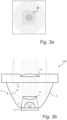
- Fig. 3b the beam paths of the luminaire 100, when in use, are illustrated.
- Incoming light originating from the LED light 5 enters the reflection collimator 3 via the first aperture 7.
- the incoming light that falls outside of the first convex lens 11 is reflected by the reflective surface 15 of the reflection collimator 3 to be guided towards the second aperture 9.
- the incoming light that falls in on the first convex lens 11 is collimated by the first convex lens 11.
- the first convex lens 11 collimates the light incident on the lens to a bundle of essentially parallel rays.
- the first convex lens 11 is typically located at a distance from the LED being shorter than the focal distance. As a result, the bundle of rays leaving the first convex lens 11 is diverging.
- the bundle of rays collimated by the first convex lens 11 then falls in on the second convex lens 13.
- the size of the second convex lens 13 is larger than the first convex lens 11 such that each light ray in the bundle of rays having passed the first convex lens 11 hits the second convex lens 13.
- the second convex lens 13 further collimates the incoming bundle of rays.
- Fig. 8 shows normalized intensity distributions 25 and 27 of a collimating optics 2 with a second convex lens 13 and without a second convex lens 13, respectively. Both intensity distributions correspond to a full width half maximum (FWHM) of 21 degrees.
- FWHM full width half maximum
- the center beam candle power (CBCP) that is, the central maximum intensity is about 25% higher for the collimating optics 2 having a second convex lens 13.
- the tails of the distribution 25 are much lighter than the tails of the distribution 27.
- the light intensity of the optical collimator 2 having a second convex lens 13 is more focused to the center of the beam in comparison to the light intensity of the optical collimator without a second convex lens.
- the light intensity may be redistributed such that a light intensity distribution which is more focused around the center of the beam and which has a higher central maximum is obtained.
- a second convex lens 13 has several consequences. At one hand, for the same light flux, a higher central maximum intensity may be obtained than with an optical collimator without a second convex lens. On the other hand, the same central maximum intensity as for a collimating optics without a second convex lens may be obtained with a lower light flux. The latter thus implies that less LEDs may be used.
- Fig. 3a illustrates an illumination spot 29 which may be obtained by directing the luminaire 100 towards a surface.
- the center of the beam spot 29 has a square-like shape. This is due to the fact that the LED die typically has a rectangular shape and that this shape is imaged by the first and the second convex lenses 11 and 13.
- Fig. 2 illustrates a luminaire 200 comprising a collimating optics 2 and a LED light 5.
- the collimating optics 2 of the luminaire 200 differs from the collimating optics 2 of the luminaire 100 in that the first and the second convex lenses 11 and 13 are Fresnel lenses.
- Each of the first and the second convex lenses 11 and 13 comprises a plurality of facets 23 and 24, respectively, also known as Fresnel zones.
- the facets 23 are concentric annular sections of the lenses 11 and 13.
- the number of facets 23 of the first convex lens 11 and the second convex lens 13 may be different. In one embodiment the number of facets of the first convex lens and/or the second convex lens is 3, 4 or 5.
- the first convex lens 11 has four facets and the second convex lens 13 has five facets.
- the intensity value of the central beam of the output light may be optimized.
- the number of facets 23 and 24 are parameters which may be tuned in order to optimize the performance of the optical collimator 2.
- the second convex lens 13 may be arranged in different ways at the second aperture 9.
- the second convex lens 13 is arranged at an inner surface of the surface plate 17.
- the second convex lens 13 is formed integrally with the surface plate 17.
- the whole collimating optics 1 is preferably formed in one piece comprising only one kind of material such as plastics.
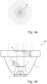
- Fig. 4b illustrates a luminaire 400 having a first convex lens 11 being a Fresnel lens with three facets 23a-b, and a second convex lens 13 being a Fresnel lens with three facets 24a-c.
- Incoming light originating from the LED 5 enters the reflection collimator 3 via the first aperture 7.
- the incoming light that falls on the first convex lens 11 is collimated by the first convex lens 11. Due to the facet structure of the first convex lens 11, the incoming light rays are collimated in an interlacing manner, meaning that the mutual order of the rays in the incoming bundle of rays is different than the mutual order of the rays in the outgoing bundle. More precisely, the refraction of the incoming light rays depends on which facet 23 a-c the light rays fall in on.
- the first and the second convex lenses 11 and 13 are arranged such that the light rays that fall in on the facet 23a of the first convex lens 11 are refracted and directed towards the facet 24a of the second convex lens 13. Further, the light rays that fall in on the facet 23b of the first convex lens 11 are refracted and directed towards the facet 24c of the second convex lens 13. Similarly, the light rays that fall in on the facet 23c of the first convex lens 11 are refracted and directed towards the facet 24b of the second convex lens 13. The bundle of light rays that has been collimated and interlaced by the first convex lens 11 is then further collimated by the convex lens 13.
- the performance of the luminaires 200 and 400 comprising Fresnel lenses is comparable to that of the luminaire 100 in terms of maximum light intensity at the center of the beam.
- the luminaires 200 and 400 have further advantages which will now be explained with respect to Fig. 4a .
- Fig. 4a illustrates a beam spot 31 obtained by directing a luminaire 200 or 400 comprising a first and a second convex lens 11 and 13 both being Fresnel lenses towards a surface.
- the beam spot 31 has a uniform and circular-symmetric appearance.
- the beam spot 31 does not comprise a rectangular-shaped image of the LED die. This is due to the fact that the Fresnel lenses interlace, i.e., redistributes the light paths originating from the LED 5 as explained above.
- the uniformity performance of the beam spot 31 may be improved. This is due to the fact that an increased number of facets results in a higher capability of redistribution or interlacing of the light rays from the LED 5.
- the number of facets 23 and 24 are parameters which may be tuned to optimize the uniformity performance of the beam spot 31 as well as to optimize the maximum intensity of the central beam of output light.
- Fig. 5a illustrates a luminaire 500a similar to that of Fig. 1 .
- Fig 5a illustrates the beam paths of light beams being reflected by the reflection collimator 3.
- the beams being reflected by the inner surface 15 are guided towards the second aperture 9.
- the diameter of the second convex lens 13 is larger than the bottom diameter of the reflection collimator 3, some of the beams are directed towards the second convex lens 13. This is an undesired feature, since the beams that fall in on the second convex lens 13 are strongly collimated and may lead to a drop in the central beam intensity.
- the drop in intensity depends on how much light that hits the top central lens after having been reflected by the reflection collimator 3.
- Fig. 5b illustrates a luminaire 500b according to an alternative embodiment.
- the luminaire 500b has a reflection collimator 3 with a wall element having two portions P 1 and P 2 .
- Portion P 1 comprises the first aperture 7 and the second portion P 2 comprises the second aperture 9.
- the first portion P 1 is arranged to diverge incoming light. More precisely, the curvature of the wall element at the first portion P 1 is arranged such that an incident bundle of light rays is reflected in a diverging manner with respect to the optical axis A of the luminaire 500b.
- the curvature of the wall element at the first portion P 1 is larger than the curvature of the corresponding portion of the wall element of luminaire 500a.
- the incoming light is guided away from the second convex lens 13.
- the second portion P 2 is arranged to collimate incoming light.
- the curvature of the wall element at the second portion P 2 is arranged such that an incident bundle of light rays is reflected in a collimating manner with respect to the optical axis A of the luminaire 500b.
- the shape of the wall element 15 at the first portion P 1 may be modeled by a first set of Bezier curves having a first set of Bezier parameters.
- the shape of the wall element 15 at the second portion P 2 may be modeled by a second set of Bezier curves having a second set of Bezier parameters.
- the first set of Bezier parameters and the second set of Bezier parameters may be optimized in accordance with an optimization method as disclosed above.
- the start values for the optimization of the first set of Bezier parameters may be chosen such that an incident bundle of light rays on the first portion P 1 is reflected in a diverging manner.
- the second set of Bezier parameters may be chosen such that an incident bundle of light rays on the second portion P 2 is collimated or is reflected in a converging manner. Since the first and the second portions P 1 and P 2 have their own set of Bezier parameters, the optimization may be carried out individually for the two portions P 1 and P 2 .
- Figs 6a-b illustrate a luminaire 600 comprising several LEDs and several collimating optics.
- any number of LEDs and collimating optics are possible.
- four LEDs 5a-d and four collimating optics 3a-d are shown.
- Each LED 5a-d corresponds to one collimating optics 3a-d.
- the LED 5a corresponds to the collimating optics 3a
- the LED 5b corresponds to the collimating optics 3b.
- the collimating optics 3a-d may be of any of the types disclosed herein.
- the LEDs 5a-d may be received in a first aperture of their corresponding collimating optics 3a-d such that the LEDs thereby are arranged to emit light through the first aperture of their corresponding collimating optics.
- the luminaire 600 further comprises a surface plate 17 which covers all of the second apertures 9a-d of the collimating optics 3a-d.
- the illustrated surface plate 17 may have a circular shape when seen from above.
- Fig. 7 illustrates an alternative embodiment of a luminaire 700 comprising several LEDs.
- the luminaire 700 comprises a plurality of LEDs.
- two LEDs 5a-b are shown.
- the luminaire 700 further comprises a collimating optics 3 according to any of the embodiments previously disclosed.
- the plurality of LEDs 5a-b are arranged to be received in the first aperture 7 of the collimating optics 3.
- the plurality of LEDs are arranged to emit light through the first aperture 7 of a common collimating optics 3.
Landscapes
- Physics & Mathematics (AREA)
- Optics & Photonics (AREA)
- General Physics & Mathematics (AREA)
- Engineering & Computer Science (AREA)
- General Engineering & Computer Science (AREA)
- Microelectronics & Electronic Packaging (AREA)
- Lenses (AREA)
- Non-Portable Lighting Devices Or Systems Thereof (AREA)
- Led Device Packages (AREA)
- Optical Elements Other Than Lenses (AREA)
- Securing Globes, Refractors, Reflectors Or The Like (AREA)
Abstract
Description
- The present invention generally relates to the field of collimation of light. In particular, it relates to a collimating optics for light emitting diode (LED) lights.
- Replacement of halogen spotlighting lamps by LEDs is a growing market. Replacing halogen lamps by LEDs is quite challenging since halogen lamps and LEDs have different properties. More specifically, a difference between halogen lamps and LEDs is that LEDs have a limited flux output in comparison to halogen lamps. In order for a LED spotlight to have the same maximum intensity at specific beam angles as a halogen spotlight, the optics of the LED spotlight therefore needs to provide a much higher intensity in the center of the beam per unit flux in order to compensate for the limited flux output. The intensity in the center of the beam per unit flux is often referred to as center beam candle power (CBCP) per lumen value, or simply Cd/lm or CBCP/lm.
- In view of the above, it is thus a challenge in LED spotlighting optics to design a compact and efficient optics in a very limited space to get a higher CBCP/lm value for specific beam angles.
- LED spotlighting optics typically comprise a total internal reflection (TIR) collimator having an opening for receiving a LED, and a central convex lens which is arranged at a distance from the opening where the LED is received. However, with such an arrangement it is difficult to collimate and redistribute the light coming through the central convex lens because the lens is positioned too close to the LED source whose size is negligible. Due to this limitation of the central lens, the light intensity distribution of the output light beam gets undesirably heavy tails and thereby it is difficult to get certain beam pattern having high CBCP/lm values at specific full width half maximum (FWHM) beam angles. The FWHM beam angles are defined by the angles relatively the center of the beam for which the light intensity is half the light intensity of the center of the beam.
- It is an object of the present invention to overcome or at least mitigate the problems discussed above, and to provide a collimating optics and a luminaire having an improved CBCP per lumen performance. In particular, it is an object to provide a collimating optics and a luminaire having an improved collimating capability without increasing the size of the optics.
- According to a first aspect of the invention, this and other objects are achieved by a collimating optics for light emitting diode, LED, lights, comprising: a reflection collimator having a first aperture for receiving a LED light and for allowing incoming light from the LED light to enter the collimator and a second aperture for allowing outgoing light to exit the collimator, the reflection collimator further having a wall element extending from the first aperture to the second aperture and having an inner reflective surface for guiding the incoming light from the first aperture towards the second aperture; a first convex lens arranged at a distance from the first aperture for refracting the incoming light; and a second convex lens arranged at the second aperture for refracting the outgoing light so as to collimate the outgoing light.
- Preferably the first convex lens arranged at a distance from the first aperture such that the first convex lens is arranged between the first aperture and the second aperture. By provision of a second convex lens at the second aperture, the light beams having been refracted by the first convex lens are further refracted and collimated by the second convex lens. Thereby, the collimating capability of the collimating optics is improved although the size of the collimating optics has not been increased. In particular, for a fixed value of the flux, the maximum intensity value may be increased since the second convex lens redistributes the light such that the light intensity distribution is more concentrated to the center of the light beam compared to if no second convex lens is present. At the same time as the maximum intensity value is improved, the FWHM beam angle is kept essentially the same. In other words, the CBCP per lumen performance is improved. As a result, fewer LED lamps, that is a lower flux, may be used in case the CBCP is to be kept at the same level as before. Alternatively, in case the same number of LED lamps is used, a higher CBCP value may be achieved.
- The first and second convex lenses may be Fresnel lenses, each having a plurality of facets. The facets are sometimes referred to as Fresnel zones. In case a simple convex lens is used, an image of the shape of the LED die may be visible in an illumination spot caused by the collimating optics. However, this is not the case if Fresnel lenses are used since Fresnel lenses redistribute the light in an interlacing way. More specifically, the mutual order of the light rays in a bundle of light rays incident on the first convex lens changes as the bundle of light rays passes and are refracted by the first and the second convex lenses. As a result, the visual uniformity of an illumination spot caused by the collimating optics is improved.
- The visual uniformity increases with the number of facets of the Fresnel lenses. In one embodiment, the number of facets of the first convex lens and/or the second
convex lens - The collimating optics may further comprise a surface plate covering at least part of the second aperture. The second convex lens may be arranged at the surface plate. This is advantageous in that it provides an easy and flexible way of arranging the second convex lens. Further, the second convex lens may easily be incorporated with an existing collimating optics. For example the second convex lens may be arranged in a recess of the surface plate. Alternatively, the second convex lens may be arranged on an outer surface of the surface plate. Yet alternatively, the second convex lens may be arranged at an inner surface of the surface plate.
- Preferably, an optical axis of the first convex lens and an optical axis of the second convex lens are aligned with an optical axis of the collimating optics, the optical axis of the reflection collimator extending from the first aperture towards the second aperture. This may be achieved in case the lenses are arranged substantially transverse to the optical axis of the reflection collimator. This is advantageous in that the collimating optics is symmetric such that the collimation of light beams is isotropic.
- The wall element of the reflection collimator may further comprise a first portion comprising the first aperture and a second portion comprising the second aperture, wherein the first portion of the wall element is arranged to diverge incoming light incident on the first portion so as to guide the incoming light away from the second convex lens, and wherein the second portion of the wall element is arranged to collimate incoming light. This is particularly advantageous in case the diameter of the second convex lens is larger than a bottom diameter of the reflection collimator. In such a case, a considerable part of the light rays being reflected by the reflection collimator to be guided towards the second aperture may be blocked by the second convex lens, resulting in loss of optical efficiency and a loss in the CBCP value. With the above arrangement, such blocking of light rays by the second convex lens is avoided and hence the efficiency and the CBCP value is improved.
- According to a second aspect of the invention, this and other objects are achieved by a luminaire comprising at least one collimating optics according to the first aspect, and at least one light emitting diode, LED, arranged to emit light through the first aperture of one of the at least one collimating optics.
- Each LED of the luminaire may have a corresponding collimating optics. Further, each LED may be arranged to emit light through the first aperture of its corresponding collimating optics. This is advantageous in that the flux is increased by having several LEDs and that the light from each LED is individually collimated to get an improved CBCP value for each LED.
- The luminaire may comprise at least two LEDs being arranged to emit light through the first aperture of a common collimating optics. By having at least two LEDs sharing a common collimating optics, the luminaire may be made more compact.
- According to a third aspect of the invention, this and other objects are achieved by a method for determining parameters of the collimating optics according to the first object, the parameters being related to the shape of the first and the second convex lens, and to the shape of the wall element of the reflection collimator, the method comprising: determining start values of the parameters based on a theoretical model of the collimating optics, optimizing a merit function with respect to the parameters of the collimating optics using the determined start values as initial values, wherein the merit function comprises a first target function related to a desired full width half maximum, FWHM, beam angle and a second target function related to a maximal light intensity in the center of a light beam output from the collimating optics.
- The merit function may further comprise a third target function being related to a desired beam profile.
- The shape of the wall element may further be modeled by means of a set of Bezier curves having a corresponding set of Bezier parameters, and wherein the parameters of the collimating optics comprises a radius of curvature of the first convex lens, a radius of curvature of the second convex lens, and the set of Bezier parameters.
- The advantages and features of the first aspect generally apply to the second and the third aspects.
- It is noted that the invention relates to all possible combinations of features recited in the claims.
- These and other aspects of the present invention will now be described in more detail, with reference to the appended drawings showing embodiment(s) of the invention.
-
Figs 1-2 are cross-sectional views of luminaires comprising a collimating optics according to embodiments. -
Figs 3a-b and4a-b illustrates beam paths of luminaires according to embodiments and corresponding illumination spots. -
Figs 5a-b illustrates beam paths of luminaires according to embodiments. -
Fig. 6a is a cross-sectional view of a luminaire according to embodiments. -
Fig. 6b is a top plan view of the luminaire ofFig. 6a . -
Fig. 7 is a cross-sectional view of a luminaire according to embodiments. -
Fig. 8 is a graph of normalized intensity distribution as a function of viewing angle. -
Fig. 9 is a flowchart of a method according to embodiments. - As illustrated in the figures, the sizes of layers and regions are exaggerated for illustrative purposes and, thus, are provided to illustrate the general structures of embodiments of the present invention. Like reference numerals refer to like elements throughout.
- The present invention will now be described more fully hereinafter with reference to the accompanying drawings, in which currently preferred embodiments of the invention are shown. This invention may, however, be embodied in many different forms and should not be construed as limited to the embodiments set forth herein; rather, these embodiments are provided for thoroughness and completeness, and fully convey the scope of the invention to the skilled person.
-
Fig. 1 illustrates aluminaire 100 comprising acollimating optics 2 and aLED light 5. Thecollimating optics 2 comprises areflection collimator 3 such as a total internal reflection collimator. Thereflection collimator 3 has a first aperture, or opening, 7 for receiving theLED light 5 and for allowing incoming light from theLED light 5 to enter thecollimator 3. Further, thereflection collimator 3 has a second aperture, or opening, 9 for allowing outgoing light to exit thereflection collimator 3. Thesecond aperture 9 is typically of larger size (diameter) than thefirst aperture 7. Thereflection collimator 3 further has awall element 15 extending from thefirst aperture 7 to thesecond aperture 9. The inner surface of thewall element 15 is reflective so as to guide the incoming light from thefirst aperture 7 towards thesecond aperture 9, thus forming a total internal reflection collimator. - The
reflection collimator 3 may be rotation-symmetric about an optical axis A of thereflection collimator 3 extending in a direction from a centre of thefirst aperture 7 towards a centre of thesecond aperture 9. Here, thereflection collimator 3 has a general cup-shaped form with thefirst aperture 7 being located at the center of the bottom of the cup and thesecond aperture 9 corresponding to the top opening of the cup. - A first
convex lens 11 having a diameter D1 is arranged at a distance S1 from thefirst aperture 7. The distance S1 may be approximately equal to or close to the focal distance of the firstconvex lens 11. The firstconvex lens 11 has a radius of curvature n. The illustrated firstconvex lens 11 is a planoconvex lens. The planar surface of the planoconvex lens faces away from thefirst aperture 7. In some cases, the first convex lens may be a conic convex lens. Further, other aspheric lens structures may be used to replace the spherical surface of the firstconvex lens 11. - Preferably, the optical axis of the first
convex lens 11 corresponds to the optical axis A of thereflection collimator 3. If so, the firstconvex lens 11 is said to be arranged transverse to the optical axis A. - The first
convex lens 11 may generally be connected to, or supported by, thereflection collimator 3 via holding means 19. The holding means 19 may be an integral part of thereflection collimator 3. For example, the firstconvex lens 11 may be connected to thereflection collimator 3 via holding means 19 which is attached to thereflection collimator 3 and which is arranged to hold the firstconvex lens 11 at a distance from thefirst aperture 7. In the illustrated example, the holding means 19 are realized by aninner wall element 19 being part of thereflection collimator 3 and extending from thefirst aperture 7 in the direction of thesecond aperture 9. The upper end of theinner wall element 19 defines an opening being located at a distance S1 from thefirst aperture 7. The opening may receive and hold the firstconvex lens 11. In alternative embodiments, the holding means 19 may comprise a frame which is arranged in thereflection collimator 3 and which is adapted to hold the firstconvex lens 11. Alternatively, the firstconvex lens 11 may be connected to thereflection collimator 3 via rods. - A second
convex lens 13 having a diameter D2 is arranged at thesecond aperture 9 at a distance S2 from thefirst aperture 7. More precisely, the secondconvex lens 13 is arranged to cover at least parts of thesecond aperture 9. The secondconvex lens 13 has a radius of curvature r2. The illustrated secondconvex lens 13 is a planoconvex lens. The planar surface of the planoconvex lens faces thesecond aperture 9. In some cases, the secondconvex lens 13 may be a conic convex lens. Further, other aspheric lens structures may be used to replace the spherical surface of the secondconvex lens 13. The secondconvex lens 13 typically has the same refractive index n, say, as the firstconvex lens 11. - Preferably, the optical axis of the second
convex lens 13 corresponds to the optical axis A of thereflection collimator 3. If so, the first convex lens is said to be arranged transverse to the optical axis A. - There are many possible alternatives for how to arrange the second
convex lens 13 at thesecond aperture 9. In the illustrated embodiment, thecollimating optics 2 comprises asurface plate 17. Generally, thesurface plate 17 may cover at least part thesecond aperture 9. Here, thesurface plate 17 covers the wholesecond aperture 9. Thesurface plate 17 is preferably made of a translucent material. Thesurface plate 17 is adapted to hold the secondconvex lens 13. More precisely, thesurface plate 17 may comprise arecess 21 which preferably is centered about the optical axis A and in which the secondconvex lens 13 may be arranged. Alternatively, the secondconvex lens 13 may be arranged on top of thesurface plate 17. Yet alternatively, thesurface plate 17 may comprise a hole being centered about the optical axis A in which the secondconvex lens 13 may be arranged. - In other embodiments, the second
convex lens 13 is neither held nor supported by asurface plate 17. For example, the secondconvex lens 13 may be held by a frame which is attached to thereflection collimator 3 or by rods extending from thereflection collimator 3. - The diameters D1 and D2 and the radiuses of curvature r1 and r2 may be varied such that a prescribed beam angle and a desired beam pattern are obtained. More precisely, the diameters D1 and D2 and, in particular, the radii of curvature r1 and r2 may be determined according to an optimization procedure which will now be described with respect to the flowchart of
Fig. 9 . - In a
first step S 100 of such an optimization procedure a start value for the diameters D1 and D2 and radii r1 and r2 are determined. For example, the start values may be calculated based on a theoretical calculation being based on a point source model and paraxial conditions. More precisely, the start values may be determined according to the following equations:


convex lens 11 and the secondconvex lens 13. The start value of D1 may be determined based on a desired ratio between the light energy that passes through the firstconvex lens 11 and the light energy that is directed towards thewall element 15 of thereflection collimator 3. The desired ratio may be determined by taking several practical considerations into account. For example, thewall element 15 of thereflection collimator 3 is more efficient in redistributing the beam pattern of a LED source to obtain a high CBCP in comparison to the firstconvex lens 11. For this reason, it is advantageous if D1 is small such that as much of the light energy as possible is directed towards thewall element 15 without passing the firstconvex lens 11. However, at the same time D1 should not be too small, since a too small diameter D1 may lead to energy losses at thesurface plate 17. More precisely, for a given optical space, the light redistribution capability of thewall element 15 of thereflection collimator 3 is limited. As a result, light may be subject to total reflection at thesurface plate 17. Other factors influencing the choice of D1 are the size and the original beam pattern of the light source used and the given optical size. - Since all real sources have a geometrical extent, the above start values do typically not give the desired beam pattern. Therefore, in a next step S102 of the method, the above start values are used as input to an optimization algorithm.
- The merit function used in the optimization comprises several target functions. For example, the merit function may be a sum of several target functions. Firstly, the merit function is based on a desired FWHM beam angle. It is important to take the FWHM beam angle into account since it is desirable to increase the CBCP while keeping the FWHW beam angle essentially constant.
- Secondly, the merit function is based on the CBCP/lm maximum value. By combining the desired FWHM beam angle and the CBCP/lm value in the same merit function, a local or global optimum value of CBCP for a desired FWHM beam angle may be obtained.
- Thirdly, and optionally, the merit function may be based on a desired beam profile. For example, the desired beam profile may be a parametric beam profile such as a Gaussian beam profile. Preferably, the merit function is based on a desired beam profile only in case it is difficult to find a solution based on the first and second target functions.
- The optimization parameters may be divided into two groups, namely parameters relating to the first and the second
convex lens wall element 15 of thereflection collimator 3. - More precisely, the optimization parameters may comprise the radius of curvature r1 of the first
convex lens 11 and the radius of curvature r2 of the secondconvex lens 13 in order to optimize the collimation of the light energy that passes through thelenses convex lens - In order to optimize the collimation of the light energy that is reflected by the
reflection collimator 3 without passing the firstconvex lens 11, the optimization parameters may comprise parameters relating to the shape of thewall element 15 of thereflection collimator 3. Start values of these parameters may also be determined in step S100. For example, thewall element 15 may be modeled by means of Bezier curves. If so, the optimization parameters may comprise the coefficients of the Bezier curves. In case Bezier curves are not suitable for modeling the shape of thewall element 15, other types of aspheric profile curves may be used to model the shape of thewall element 15. In that case, the optimization parameters may comprise the coefficients of the aspheric profile curves. - Alternatively, the optimization may be performed in a sequential fashion. For example, first the parameters could be optimized with respect to the first target function. Then, in a separate step, the parameters could be optimized with respect to the second target function. Similarly, the parameters could be optimized separately with respect to the third target function.
- The function of the
luminaire 100 will now be described with reference toFigs 3a-b andFig. 8 . - In
Fig. 3b the beam paths of theluminaire 100, when in use, are illustrated. Incoming light originating from theLED light 5 enters thereflection collimator 3 via thefirst aperture 7. The incoming light that falls outside of the firstconvex lens 11 is reflected by thereflective surface 15 of thereflection collimator 3 to be guided towards thesecond aperture 9. - The incoming light that falls in on the first
convex lens 11 is collimated by the firstconvex lens 11. In case theLED light 5 is located in the focal point of the firstconvex lens 11, the firstconvex lens 11 collimates the light incident on the lens to a bundle of essentially parallel rays. However, due to size restrictions of thereflection collimator 3, the firstconvex lens 11 is typically located at a distance from the LED being shorter than the focal distance. As a result, the bundle of rays leaving the firstconvex lens 11 is diverging. - The bundle of rays collimated by the first
convex lens 11 then falls in on the secondconvex lens 13. Preferably, the size of the secondconvex lens 13 is larger than the firstconvex lens 11 such that each light ray in the bundle of rays having passed the firstconvex lens 11 hits the secondconvex lens 13. The secondconvex lens 13 further collimates the incoming bundle of rays. Thus, by provision of the secondconvex lens 13, the collimating capability of thecollimating optics 2 is improved without increasing the size of the optics. - In
Fig. 8 , the performance of acollimating optics 2 comprising a secondconvex lens 13 is compared to the performance of a collimating optics without a secondconvex lens 13.Fig. 8 shows normalizedintensity distributions collimating optics 2 with a secondconvex lens 13 and without a secondconvex lens 13, respectively. Both intensity distributions correspond to a full width half maximum (FWHM) of 21 degrees. As can be seen in the graph, the center beam candle power (CBCP), that is, the central maximum intensity is about 25% higher for thecollimating optics 2 having a secondconvex lens 13. Further, the tails of thedistribution 25 are much lighter than the tails of thedistribution 27. This means that the light intensity of theoptical collimator 2 having a secondconvex lens 13 is more focused to the center of the beam in comparison to the light intensity of the optical collimator without a second convex lens. Thus, by provision of the secondconvex lens 13, the light intensity may be redistributed such that a light intensity distribution which is more focused around the center of the beam and which has a higher central maximum is obtained. - In practice, the provision of a second
convex lens 13 has several consequences. At one hand, for the same light flux, a higher central maximum intensity may be obtained than with an optical collimator without a second convex lens. On the other hand, the same central maximum intensity as for a collimating optics without a second convex lens may be obtained with a lower light flux. The latter thus implies that less LEDs may be used. -
Fig. 3a illustrates anillumination spot 29 which may be obtained by directing theluminaire 100 towards a surface. The center of thebeam spot 29 has a square-like shape. This is due to the fact that the LED die typically has a rectangular shape and that this shape is imaged by the first and the secondconvex lenses -
Fig. 2 illustrates aluminaire 200 comprising acollimating optics 2 and aLED light 5. Thecollimating optics 2 of theluminaire 200 differs from thecollimating optics 2 of theluminaire 100 in that the first and the secondconvex lenses convex lenses facets facets 23 are concentric annular sections of thelenses facets 23 of the firstconvex lens 11 and the secondconvex lens 13 may be different. In one embodiment the number of facets of the first convex lens and/or the second convex lens is 3, 4 or 5. In the illustrated embodiment, the firstconvex lens 11 has four facets and the secondconvex lens 13 has five facets. By varying the number offacets convex lens 11 and the secondconvex lens 13, the intensity value of the central beam of the output light may be optimized. Thus, the number offacets optical collimator 2. - Similar to the disclosure with respect to
Fig. 1 , the secondconvex lens 13 may be arranged in different ways at thesecond aperture 9. In the illustrated example, the secondconvex lens 13 is arranged at an inner surface of thesurface plate 17. Preferably, in order to simplify the manufacturing of thecollimating optics 1, the secondconvex lens 13 is formed integrally with thesurface plate 17. Moreover, the wholecollimating optics 1 is preferably formed in one piece comprising only one kind of material such as plastics. - The function of a luminaire comprising Fresnel lenses as first and second
convex lenses Figs 4a-b . -
Fig. 4b illustrates aluminaire 400 having a firstconvex lens 11 being a Fresnel lens with threefacets 23a-b, and a secondconvex lens 13 being a Fresnel lens with three facets 24a-c. - Incoming light originating from the
LED 5 enters thereflection collimator 3 via thefirst aperture 7. The incoming light that falls on the firstconvex lens 11 is collimated by the firstconvex lens 11. Due to the facet structure of the firstconvex lens 11, the incoming light rays are collimated in an interlacing manner, meaning that the mutual order of the rays in the incoming bundle of rays is different than the mutual order of the rays in the outgoing bundle. More precisely, the refraction of the incoming light rays depends on whichfacet 23 a-c the light rays fall in on. - In the illustrated example, the first and the second
convex lenses facet 23a of the firstconvex lens 11 are refracted and directed towards the facet 24a of the secondconvex lens 13. Further, the light rays that fall in on thefacet 23b of the firstconvex lens 11 are refracted and directed towards thefacet 24c of the secondconvex lens 13. Similarly, the light rays that fall in on thefacet 23c of the firstconvex lens 11 are refracted and directed towards thefacet 24b of the secondconvex lens 13. The bundle of light rays that has been collimated and interlaced by the firstconvex lens 11 is then further collimated by theconvex lens 13. - The performance of the
luminaires luminaire 100 in terms of maximum light intensity at the center of the beam. However, theluminaires Fig. 4a . -
Fig. 4a illustrates abeam spot 31 obtained by directing aluminaire convex lens beam spot 31 has a uniform and circular-symmetric appearance. In particular, thebeam spot 31 does not comprise a rectangular-shaped image of the LED die. This is due to the fact that the Fresnel lenses interlace, i.e., redistributes the light paths originating from theLED 5 as explained above. - By increasing the number of
facets beam spot 31 may be improved. This is due to the fact that an increased number of facets results in a higher capability of redistribution or interlacing of the light rays from theLED 5. Thus, the number offacets beam spot 31 as well as to optimize the maximum intensity of the central beam of output light. -
Fig. 5a illustrates aluminaire 500a similar to that ofFig. 1 . In particular,Fig 5a illustrates the beam paths of light beams being reflected by thereflection collimator 3. The beams being reflected by theinner surface 15 are guided towards thesecond aperture 9. However, in case the diameter of the secondconvex lens 13 is larger than the bottom diameter of thereflection collimator 3, some of the beams are directed towards the secondconvex lens 13. This is an undesired feature, since the beams that fall in on the secondconvex lens 13 are strongly collimated and may lead to a drop in the central beam intensity. The drop in intensity depends on how much light that hits the top central lens after having been reflected by thereflection collimator 3. -
Fig. 5b illustrates aluminaire 500b according to an alternative embodiment. Theluminaire 500b has areflection collimator 3 with a wall element having two portions P1 and P2. Portion P1 comprises thefirst aperture 7 and the second portion P2 comprises thesecond aperture 9. The first portion P1 is arranged to diverge incoming light. More precisely, the curvature of the wall element at the first portion P1 is arranged such that an incident bundle of light rays is reflected in a diverging manner with respect to the optical axis A of theluminaire 500b. Typically, the curvature of the wall element at the first portion P1 is larger than the curvature of the corresponding portion of the wall element ofluminaire 500a. In this way, the incoming light is guided away from the secondconvex lens 13. Similarly, the second portion P2 is arranged to collimate incoming light. Particularly, the curvature of the wall element at the second portion P2 is arranged such that an incident bundle of light rays is reflected in a collimating manner with respect to the optical axis A of theluminaire 500b. - In practice, the shape of the
wall element 15 at the first portion P1 may be modeled by a first set of Bezier curves having a first set of Bezier parameters. Similarly, the shape of thewall element 15 at the second portion P2 may be modeled by a second set of Bezier curves having a second set of Bezier parameters. The first set of Bezier parameters and the second set of Bezier parameters may be optimized in accordance with an optimization method as disclosed above. In particular, the start values for the optimization of the first set of Bezier parameters may be chosen such that an incident bundle of light rays on the first portion P1 is reflected in a diverging manner. Similarly, the second set of Bezier parameters may be chosen such that an incident bundle of light rays on the second portion P2 is collimated or is reflected in a converging manner. Since the first and the second portions P1 and P2 have their own set of Bezier parameters, the optimization may be carried out individually for the two portions P1 and P2. -
Figs 6a-b illustrate aluminaire 600 comprising several LEDs and several collimating optics. In principle, any number of LEDs and collimating optics are possible. Here, for illustration purposes, fourLEDs 5a-d and fourcollimating optics 3a-d are shown. - Each
LED 5a-d corresponds to onecollimating optics 3a-d. For example, in the illustrated example, theLED 5a corresponds to thecollimating optics 3a and theLED 5b corresponds to thecollimating optics 3b. Thecollimating optics 3a-d may be of any of the types disclosed herein. In particular, theLEDs 5a-d may be received in a first aperture of their correspondingcollimating optics 3a-d such that the LEDs thereby are arranged to emit light through the first aperture of their corresponding collimating optics.
Theluminaire 600 further comprises asurface plate 17 which covers all of thesecond apertures 9a-d of thecollimating optics 3a-d. The illustratedsurface plate 17 may have a circular shape when seen from above. -
Fig. 7 illustrates an alternative embodiment of aluminaire 700 comprising several LEDs. Theluminaire 700 comprises a plurality of LEDs. Here, for illustration purposes, twoLEDs 5a-b are shown. Theluminaire 700 further comprises acollimating optics 3 according to any of the embodiments previously disclosed. The plurality ofLEDs 5a-b are arranged to be received in thefirst aperture 7 of thecollimating optics 3. Thus, the plurality of LEDs are arranged to emit light through thefirst aperture 7 of acommon collimating optics 3. - The person skilled in the art realizes that the present invention by no means is limited to the preferred embodiments described above. On the contrary, many modifications and variations are possible within the scope of the appended claims. For example, the embodiments disclosed with respect to
Figs 6 and 7 could be combined into a luminaire comprising several collimating optics similar to the embodiment ofFigs 6a-b , but wherein each collimating optics is associated with several LEDs as shown inFig. 7 . - Additionally, variations to the disclosed embodiments can be understood and effected by the skilled person in practicing the claimed invention, from a study of the drawings, the disclosure, and the appended claims. In the claims, the word "comprising" does not exclude other elements or steps, and the indefinite article "a" or "an" does not exclude a plurality. The mere fact that certain measures are recited in mutually different dependent claims does not indicate that a combination of these measured cannot be used to advantage.
Claims (14)
- A collimating optics (2) for light emitting diode lights (5), LED lights, comprising:- a reflection collimator (3) having a first aperture (7) for receiving a LED light (5) and for allowing incoming light from the LED light to enter said collimator (3) and a second aperture (9) for allowing outgoing light to exit said collimator (3), the reflection collimator (3) further having a wall element (15) extending from said first aperture (7) to said second aperture (9) and having an inner reflective surface for guiding said incoming light from said first aperture (7) towards said second aperture (9),- a first convex lens (11) arranged at a distance from the first aperture (7) for refracting said incoming light,- a second convex lens (13) arranged at the second aperture (9) for refracting said outgoing light so as to collimate said outgoing light, andwherein the wall element comprises a first portion comprising the first aperture and a second portion comprising the second aperture, wherein the first portion of the wall element is arranged to diverge incoming light incident on the first portion so as to guide the incoming light away from the second convex lens, and wherein the second portion of the wall element is arranged to collimate incoming light.
- The collimating optics according to claim 1, wherein the first and the second convex lenses are Fresnel lenses each having a plurality of facets.
- The collimating optics according to claim 2, wherein the number of facets of the first convex lens and the second convex lens are different.
- The collimating optics according to claim 3, wherein the number of facets of the first convex lens and/or of the second convex lens is 3, 4 or 5.
- The collimating optics according to claim 1, further comprising- a surface plate covering at least part of the second aperture, wherein the second convex lens is arranged at the surface plate.
- The collimating optics according to claim 5, wherein the second convex lens is arranged in a recess of the surface plate.
- The collimating optics according to claim 5, wherein the second convex lens is arranged on an outer surface of the surface plate.
- The collimating optics according to claim 1, wherein an optical axis of the first convex lens and an optical axis of the second convex lens are aligned with an optical axis of the reflection collimator, the optical axis of the reflection collimator extending from the first aperture towards the second aperture.
- A luminaire (100) comprising- at least one collimating optics (2) according to claim 1, and- at least one light emitting diode (5), LED, arranged to emit light through the first aperture (7) of one of the at least one collimating optics (2).
- The luminaire according to claim 9, wherein each LED (5) of the at least one LED has a corresponding collimating optics, and wherein each LED is arranged to emit light through the first aperture of its corresponding collimating optics.
- The luminaire according to claim 9, comprising at least two LEDs being arranged to emit light through the first aperture of a common collimating optics.
- A method for determining parameters of the collimating optics (2) of claim 1, the parameters being related to the shape of the first (11) and the second convex lens (13), and to the shape of the wall element (15) of the reflection collimator (3), the method comprising:- determining start values (S100) of the parameters based on a theoretical model of the collimating optics (2),- optimizing (S102) a merit function with respect to the parameters of the collimating optics (2) using the determined start values as initial values, wherein the merit function comprises a first target function related to a desired full width half maximum, FWHM, beam angle and a second target function related to a maximal light intensity in the center of a light beam output from the collimating optics (1).
- The method according to claim 12, wherein the merit function further comprises a third target function being related to a desired beam profile.
- The method according to claim 12, wherein the shape of the wall element is modeled by means of a set of Bezier curves having a corresponding set of Bezier parameters, and wherein the parameters of the collimating optics comprises a radius of curvature of the first convex lens, a radius of curvature of the second convex lens and the set of Bezier parameters.
Applications Claiming Priority (3)
| Application Number | Priority Date | Filing Date | Title |
|---|---|---|---|
| CN2011083883 | 2011-12-13 | ||
| PCT/IB2012/056937 WO2013088299A1 (en) | 2011-12-13 | 2012-12-04 | Optical collimator for led lights |
| EP12819137.6A EP2791724A1 (en) | 2011-12-13 | 2012-12-04 | Optical collimator for led lights |
Related Parent Applications (1)
| Application Number | Title | Priority Date | Filing Date |
|---|---|---|---|
| EP12819137.6A Division EP2791724A1 (en) | 2011-12-13 | 2012-12-04 | Optical collimator for led lights |
Publications (3)
| Publication Number | Publication Date |
|---|---|
| EP4273443A2 true EP4273443A2 (en) | 2023-11-08 |
| EP4273443A3 EP4273443A3 (en) | 2023-12-20 |
| EP4273443B1 EP4273443B1 (en) | 2026-02-11 |
Family
ID=47628403
Family Applications (2)
| Application Number | Title | Priority Date | Filing Date |
|---|---|---|---|
| EP23186632.8A Active EP4273443B1 (en) | 2011-12-13 | 2012-12-04 | Optical collimator for led lights |
| EP12819137.6A Withdrawn EP2791724A1 (en) | 2011-12-13 | 2012-12-04 | Optical collimator for led lights |
Family Applications After (1)
| Application Number | Title | Priority Date | Filing Date |
|---|---|---|---|
| EP12819137.6A Withdrawn EP2791724A1 (en) | 2011-12-13 | 2012-12-04 | Optical collimator for led lights |
Country Status (7)
| Country | Link |
|---|---|
| US (1) | US10254521B2 (en) |
| EP (2) | EP4273443B1 (en) |
| JP (1) | JP6198748B2 (en) |
| CN (1) | CN103988110B (en) |
| IN (1) | IN2014CN04756A (en) |
| RU (1) | RU2670177C2 (en) |
| WO (1) | WO2013088299A1 (en) |
Families Citing this family (79)
| Publication number | Priority date | Publication date | Assignee | Title |
|---|---|---|---|---|
| US8118447B2 (en) | 2007-12-20 | 2012-02-21 | Altair Engineering, Inc. | LED lighting apparatus with swivel connection |
| US8360599B2 (en) | 2008-05-23 | 2013-01-29 | Ilumisys, Inc. | Electric shock resistant L.E.D. based light |
| US8324817B2 (en) | 2008-10-24 | 2012-12-04 | Ilumisys, Inc. | Light and light sensor |
| US8901823B2 (en) | 2008-10-24 | 2014-12-02 | Ilumisys, Inc. | Light and light sensor |
| US8214084B2 (en) | 2008-10-24 | 2012-07-03 | Ilumisys, Inc. | Integration of LED lighting with building controls |
| US7938562B2 (en) | 2008-10-24 | 2011-05-10 | Altair Engineering, Inc. | Lighting including integral communication apparatus |
| US8653984B2 (en) | 2008-10-24 | 2014-02-18 | Ilumisys, Inc. | Integration of LED lighting control with emergency notification systems |
| WO2011119958A1 (en) | 2010-03-26 | 2011-09-29 | Altair Engineering, Inc. | Inside-out led bulb |
| WO2011119921A2 (en) | 2010-03-26 | 2011-09-29 | Altair Engineering, Inc. | Led light with thermoelectric generator |
| GB2484713A (en) | 2010-10-21 | 2012-04-25 | Optovate Ltd | Illumination apparatus |
| EP2633227B1 (en) | 2010-10-29 | 2018-08-29 | iLumisys, Inc. | Mechanisms for reducing risk of shock during installation of light tube |
| US9184518B2 (en) | 2012-03-02 | 2015-11-10 | Ilumisys, Inc. | Electrical connector header for an LED-based light |
| WO2014008463A1 (en) | 2012-07-06 | 2014-01-09 | Ilumisys, Inc. | Power supply assembly for led-based light tube |
| US9271367B2 (en) | 2012-07-09 | 2016-02-23 | Ilumisys, Inc. | System and method for controlling operation of an LED-based light |
| US9285084B2 (en) | 2013-03-14 | 2016-03-15 | Ilumisys, Inc. | Diffusers for LED-based lights |
| AT514121B1 (en) * | 2013-04-12 | 2015-06-15 | Zizala Lichtsysteme Gmbh | Lighting unit for a vehicle headlight and vehicle headlights |
| CN104214547B (en) * | 2013-05-31 | 2016-09-07 | 深圳市海洋王照明工程有限公司 | Lens and use the lighting device of these lens |
| WO2014195876A1 (en) * | 2013-06-07 | 2014-12-11 | Koninklijke Philips N.V. | Lens and lighting device |
| FR3008777B1 (en) * | 2013-07-22 | 2017-12-29 | Renault Sas | LIGHTING SYSTEM, IN PARTICULAR FOR A MOTOR VEHICLE LIGHTING BODY, WITH INTEGRATED LEDS |
| US9267650B2 (en) | 2013-10-09 | 2016-02-23 | Ilumisys, Inc. | Lens for an LED-based light |
| WO2015112437A1 (en) | 2014-01-22 | 2015-07-30 | Ilumisys, Inc. | Led-based light with addressed leds |
| WO2015110392A1 (en) * | 2014-01-27 | 2015-07-30 | Koninklijke Philips N.V. | Optical device and luminaire |
| US9435515B2 (en) * | 2014-01-31 | 2016-09-06 | Energizer Brands, Llc | Near-field lens with convex hyperbolic surface |
| FR3019314B1 (en) * | 2014-03-28 | 2017-08-11 | Gaggione Sas | LIGHT COLLIMATOR |
| US9510400B2 (en) | 2014-05-13 | 2016-11-29 | Ilumisys, Inc. | User input systems for an LED-based light |
| KR101622095B1 (en) * | 2014-06-02 | 2016-05-18 | 현대모비스 주식회사 | Lamp apparatus for an automobile |
| WO2015185519A1 (en) * | 2014-06-02 | 2015-12-10 | Koninklijke Philips N.V. | An optical system for collimation of light |
| EP2955430B1 (en) * | 2014-06-12 | 2019-07-31 | Harman Professional Denmark ApS | Illumination device with uniform light beams |
| JP6606832B2 (en) * | 2015-02-26 | 2019-11-20 | 三菱電機株式会社 | lighting equipment |
| KR101697212B1 (en) * | 2015-04-28 | 2017-02-01 | 동부라이텍 주식회사 | Lighting apparatus |
| JP6094623B2 (en) * | 2015-05-18 | 2017-03-15 | 株式会社遠藤照明 | Fresnel lens for lighting fixture and lighting fixture having the same |
| CN104864360B (en) * | 2015-05-27 | 2023-05-02 | 漳州立达信光电子科技有限公司 | lens structure |
| US10161568B2 (en) | 2015-06-01 | 2018-12-25 | Ilumisys, Inc. | LED-based light with canted outer walls |
| US10995915B2 (en) * | 2015-09-02 | 2021-05-04 | Lumileds Llc | LED module and lighting module |
| DE102015011714A1 (en) * | 2015-09-07 | 2017-03-09 | Bartenbach Holding Gmbh | lighting device |
| JP2017067970A (en) * | 2015-09-30 | 2017-04-06 | 日本電産サンキョー株式会社 | Optical unit and converging lens |
| KR101764821B1 (en) * | 2015-10-12 | 2017-08-04 | 동부라이텍 주식회사 | Lighting apparatus |
| JP2017108020A (en) * | 2015-12-10 | 2017-06-15 | パナソニックIpマネジメント株式会社 | Lens unit, led module and lighting apparatus using the same |
| KR102659369B1 (en) * | 2016-03-23 | 2024-04-22 | 쑤저우 레킨 세미컨덕터 컴퍼니 리미티드 | Optical module |
| JP6850816B2 (en) * | 2016-05-12 | 2021-03-31 | ルミレッズ ホールディング ベーフェー | Parallel optics on die |
| JP6861538B2 (en) * | 2016-06-22 | 2021-04-21 | 三菱電機株式会社 | Light source device |
| NL2018334B1 (en) * | 2017-02-06 | 2018-09-03 | Jozef Horvath Gusztav | UV COATING HARD DEVICE |
| JP2018147702A (en) * | 2017-03-06 | 2018-09-20 | 三菱電機株式会社 | Lighting device |
| JP7154219B2 (en) | 2017-03-17 | 2022-10-17 | ルミレッズ ホールディング ベーフェー | Multifocal collimating lens and headlight assembly for automotive low beam |
| GB201705365D0 (en) | 2017-04-03 | 2017-05-17 | Optovate Ltd | Illumination apparatus |
| GB201705364D0 (en) * | 2017-04-03 | 2017-05-17 | Optovate Ltd | Illumination apparatus |
| EP3438524A1 (en) | 2017-08-02 | 2019-02-06 | ERCO GmbH | Luminaire |
| KR101940921B1 (en) * | 2017-08-18 | 2019-01-22 | 주식회사 포스코 | Pattern glass and solar cell module having thereof |
| GB201718307D0 (en) | 2017-11-05 | 2017-12-20 | Optovate Ltd | Display apparatus |
| WO2019137909A1 (en) * | 2018-01-10 | 2019-07-18 | Signify Holding B.V. | A led lamp and a method of controlling a led lamp |
| GB201800574D0 (en) * | 2018-01-14 | 2018-02-28 | Optovate Ltd | Illumination apparatus |
| GB201803767D0 (en) | 2018-03-09 | 2018-04-25 | Optovate Ltd | Illumination apparatus |
| US11236888B2 (en) * | 2018-04-19 | 2022-02-01 | Signify Holding B.V. | Lighting device having light mixing optics and ring-shaped collimating structure |
| DE202018102205U1 (en) * | 2018-04-20 | 2019-07-24 | Zumtobel Lighting Gmbh | Lens arrangement for directing the light emitted by a light source |
| GB201807747D0 (en) | 2018-05-13 | 2018-06-27 | Optovate Ltd | Colour micro-LED display apparatus |
| JP6912732B2 (en) * | 2018-08-31 | 2021-08-04 | 日亜化学工業株式会社 | Light emitting device and its manufacturing method |
| EP3627637B1 (en) * | 2018-09-18 | 2021-04-21 | ZKW Group GmbH | Method for connecting a collimating optics unit with a multi-mode laser light source at an optimized position |
| DE102018133386A1 (en) * | 2018-12-21 | 2020-06-25 | Erco Gmbh | lamp |
| RU2706219C1 (en) * | 2019-03-19 | 2019-11-15 | Российская Федерация, от имени которой выступает Государственная корпорация по атомной энергии "Росатом" (Госкорпорация "Росатом") | Collimator for hard x-rays |
| TWI912252B (en) | 2019-07-02 | 2026-01-21 | 美商瑞爾D斯帕克有限責任公司 | Directional display apparatus |
| CN114616498A (en) | 2019-08-23 | 2022-06-10 | 瑞尔D斯帕克有限责任公司 | Directional lighting device and anti-peeping display |
| WO2021050967A1 (en) | 2019-09-11 | 2021-03-18 | Reald Spark, Llc | Directional illumination apparatus and privacy display |
| WO2021050918A1 (en) | 2019-09-11 | 2021-03-18 | Reald Spark, Llc | Switchable illumination apparatus and privacy display |
| KR102937412B1 (en) | 2019-10-03 | 2026-03-12 | 리얼디 스파크, 엘엘씨 | Lighting device comprising passive optical nanostructures |
| US11162661B2 (en) | 2019-10-03 | 2021-11-02 | Reald Spark, Llc | Illumination apparatus comprising passive optical nanostructures |
| US11774063B2 (en) * | 2019-10-28 | 2023-10-03 | Signify Holding B.V. | Color mixing with total internal reflector and center reflector |
| JP7231831B2 (en) | 2019-10-30 | 2023-03-02 | 日亜化学工業株式会社 | Light source device |
| JP7148813B2 (en) | 2019-10-30 | 2022-10-06 | 日亜化学工業株式会社 | Light source device |
| FR3103258B1 (en) * | 2019-11-20 | 2021-11-05 | Valeo Vision | LIGHTING DEVICE FOR MOTOR VEHICLES INCLUDING A COLLIMATOR |
| CN114746921A (en) * | 2019-12-23 | 2022-07-12 | 深圳大学 | Anti-glare lens unit and LED light source system |
| JP7291086B2 (en) * | 2020-01-29 | 2023-06-14 | スタンレー電気株式会社 | lighting equipment |
| CN115136065A (en) | 2020-02-20 | 2022-09-30 | 瑞尔D斯帕克有限责任公司 | Illumination and display device |
| JP6867533B1 (en) | 2020-05-20 | 2021-04-28 | 株式会社アルス | Light source device |
| GB2590744B (en) * | 2020-06-03 | 2022-02-02 | Plessey Semiconductors Ltd | Spacer micro-LED architecture for microdisplay applications |
| GB2595685B (en) * | 2020-06-03 | 2024-08-07 | Plessey Semiconductors Ltd | Spacer LED architecture for high efficiency micro LED displays |
| US11782205B2 (en) | 2021-04-28 | 2023-10-10 | Nichia Corporation | Light-emitting device including movement mechanism |
| EP4359862B1 (en) | 2021-06-22 | 2026-05-06 | RealD Spark, LLC | Illumination apparatus |
| CN116524815B (en) * | 2023-05-05 | 2026-06-09 | 厦门天马显示科技有限公司 | Display panel and display device |
| JP2025180389A (en) * | 2024-05-30 | 2025-12-11 | 日亜化学工業株式会社 | Optical components, light source modules, liquid crystal display devices |
Family Cites Families (38)
| Publication number | Priority date | Publication date | Assignee | Title |
|---|---|---|---|---|
| US2224178A (en) * | 1940-05-08 | 1940-12-10 | Ralph E Bitner | Catadioptrical lens system |
| JPS59143117A (en) | 1983-02-04 | 1984-08-16 | Saibishiya:Kk | Condenser |
| CN1037573A (en) * | 1988-05-09 | 1989-11-29 | 汽车电子、汽车拖拉机电器装置科研生产联合企业 | Whole pressed light collimator |
| DE4315393C2 (en) * | 1993-05-08 | 2002-10-31 | Bosch Gmbh Robert | Motor vehicle headlights with a reflector and a lens |
| JPH07287226A (en) | 1994-04-18 | 1995-10-31 | Hitachi Ltd | Liquid crystal display |
| TW512214B (en) * | 2000-01-07 | 2002-12-01 | Koninkl Philips Electronics Nv | Luminaire |
| US6547423B2 (en) * | 2000-12-22 | 2003-04-15 | Koninklijke Phillips Electronics N.V. | LED collimation optics with improved performance and reduced size |
| US6632004B2 (en) * | 2000-12-27 | 2003-10-14 | Canon Kabushiki Kaisha | Lighting device |
| DE10256365A1 (en) * | 2001-12-04 | 2003-07-17 | Ccs Inc | Light radiation device for testing semiconductor chip, has lens mounted on optical fibers in one-to-one correspondence and closer to light transmission end of optical fibers |
| JP3996164B2 (en) * | 2002-05-17 | 2007-10-24 | シーシーエス株式会社 | Light emitting diode device and method for manufacturing light emitting diode device |
| JP2004259541A (en) | 2003-02-25 | 2004-09-16 | Cateye Co Ltd | lighting equipment |
| JP4661149B2 (en) | 2003-12-22 | 2011-03-30 | セイコーエプソン株式会社 | Lighting device and projector |
| JP4497348B2 (en) * | 2004-01-13 | 2010-07-07 | 株式会社小糸製作所 | Vehicle lighting |
| DE602004011186T2 (en) * | 2004-05-14 | 2009-01-22 | C.R.F. Società Consortile per Azioni, Orbassano | Unit for projecting a light beam, an optical device for the unit, and vehicle front light device |
| EP1648037B1 (en) * | 2004-10-14 | 2009-12-30 | C.R.F. Società Consortile per Azioni | Optical element and module for the projection of a light beam, and motor vehicle lamp including a plurality of such modules |
| US7748872B2 (en) * | 2005-07-22 | 2010-07-06 | Cooper Technologies Company | Light-conducting pedestal configuration for an LED apparatus which collects almost all and distributes substantially all of the light from the LED |
| KR100722590B1 (en) | 2005-08-30 | 2007-05-28 | 삼성전기주식회사 | LED lens for backlight |
| JP4993434B2 (en) * | 2005-11-18 | 2012-08-08 | スタンレー電気株式会社 | White LED lighting device |
| US7461960B2 (en) * | 2006-05-05 | 2008-12-09 | Zweibruder Optoelectronics | LED illumination module |
| US20080030974A1 (en) * | 2006-08-02 | 2008-02-07 | Abu-Ageel Nayef M | LED-Based Illumination System |
| CN100516642C (en) * | 2006-08-03 | 2009-07-22 | 哈利盛东芝照明株式会社 | Hollow type plate illuminating device |
| BRPI0716036A2 (en) | 2006-08-10 | 2013-09-24 | Upstream Engineering Oy | Method and illuminating device |
| JP4355958B2 (en) * | 2006-11-21 | 2009-11-04 | いすゞ自動車株式会社 | Vehicle door structure |
| ATE508108T1 (en) * | 2007-02-06 | 2011-05-15 | Chelsea Therapeutics Inc | NEW COMPOUNDS, METHOD FOR THEIR PRODUCTION AND THEIR USE |
| WO2009025771A2 (en) * | 2007-08-17 | 2009-02-26 | Brightburst Technologies, Llc | Parameterized optical system and method |
| US20090128921A1 (en) * | 2007-11-15 | 2009-05-21 | Philips Solid-State Lighting Solutions | Led collimator having spline surfaces and related methods |
| JP2010067439A (en) * | 2008-09-10 | 2010-03-25 | Harison Toshiba Lighting Corp | Surface light-emitting device, and display device |
| US8068288B1 (en) * | 2008-09-15 | 2011-11-29 | Triformix, Inc. | Thin stepped tulip lens |
| CN101750643B (en) * | 2008-12-05 | 2012-12-19 | 鸿富锦精密工业(深圳)有限公司 | Lens and light source module adopting lens |
| JP2010224089A (en) * | 2009-03-23 | 2010-10-07 | Brother Ind Ltd | Prism |
| CN201680286U (en) * | 2009-11-24 | 2010-12-22 | 帝欧(上海)光电科技有限公司 | Highly effective LED lens and luminescent module |
| CN102102850A (en) * | 2009-12-16 | 2011-06-22 | 富准精密工业(深圳)有限公司 | Lens and light-emitting diode module using same |
| TW201122560A (en) * | 2009-12-30 | 2011-07-01 | Genius Electronic Optical Co Ltd | Light guide lens and bicycle headlight using the same. |
| US8858022B2 (en) * | 2011-05-05 | 2014-10-14 | Ledengin, Inc. | Spot TIR lens system for small high-power emitter |
| TW201139935A (en) * | 2010-05-05 | 2011-11-16 | Shun-Wei Yang | An LED lighting device and the asymmetric lamp cup thereof |
| US8649094B2 (en) | 2010-05-21 | 2014-02-11 | Eastman Kodak Company | Low thermal stress birefringence imaging lens |
| JP5608048B2 (en) * | 2010-11-04 | 2014-10-15 | 日東光学株式会社 | Lighting lens |
| US20130135358A1 (en) * | 2011-11-30 | 2013-05-30 | Qualcomm Mems Technologies, Inc. | Light collimating manifold for producing multiple virtual light sources |
-
2012
- 2012-12-04 WO PCT/IB2012/056937 patent/WO2013088299A1/en not_active Ceased
- 2012-12-04 US US14/365,127 patent/US10254521B2/en active Active
- 2012-12-04 IN IN4756CHN2014 patent/IN2014CN04756A/en unknown
- 2012-12-04 RU RU2014128527A patent/RU2670177C2/en active
- 2012-12-04 JP JP2014546683A patent/JP6198748B2/en active Active
- 2012-12-04 EP EP23186632.8A patent/EP4273443B1/en active Active
- 2012-12-04 EP EP12819137.6A patent/EP2791724A1/en not_active Withdrawn
- 2012-12-04 CN CN201280061479.9A patent/CN103988110B/en active Active
Also Published As
| Publication number | Publication date |
|---|---|
| US20140316742A1 (en) | 2014-10-23 |
| US10254521B2 (en) | 2019-04-09 |
| JP6198748B2 (en) | 2017-09-20 |
| RU2014128527A (en) | 2016-02-10 |
| CN103988110A (en) | 2014-08-13 |
| JP2015507817A (en) | 2015-03-12 |
| IN2014CN04756A (en) | 2015-09-18 |
| WO2013088299A1 (en) | 2013-06-20 |
| CN103988110B (en) | 2018-09-28 |
| EP4273443A3 (en) | 2023-12-20 |
| RU2670177C2 (en) | 2018-10-18 |
| EP2791724A1 (en) | 2014-10-22 |
| EP4273443B1 (en) | 2026-02-11 |
Similar Documents
| Publication | Publication Date | Title |
|---|---|---|
| EP4273443B1 (en) | Optical collimator for led lights | |
| US10024517B2 (en) | Lens member and light-emitting device using same | |
| US7083313B2 (en) | Side-emitting collimator | |
| US10295153B2 (en) | Optical system for producing uniform illumination | |
| US9046241B2 (en) | High efficiency directional light source using lens optics | |
| US7618161B2 (en) | Fresnel lens and lighting apparatus provided with the Fresnel lens | |
| US20100296283A1 (en) | Total internal reflective (tir) optic light assembly | |
| EP2721656B1 (en) | Led light source | |
| JP2015529849A (en) | Low profile multiple lens TIR | |
| US9234639B2 (en) | Compact searchlight utilizing the concept of merging into a single beam the beams of multiple sources of concentrated light | |
| JP2015507817A5 (en) | ||
| JP2012150274A (en) | Luminous flux control member, light-emitting device including luminous flux control member, and lighting apparatus including light-emitting device | |
| WO2015116926A1 (en) | Collimating lens with convex hyperbolic surface | |
| US8746936B2 (en) | Luminaire and optical component | |
| US20130329451A1 (en) | Surgical light with led light guiding and focusing structure and method | |
| WO2013035036A1 (en) | A collimator structure and lighting device | |
| JP5828604B2 (en) | Lighting device | |
| JP2013089291A (en) | Optical lens, optical module, optical system, and lamp | |
| TW201209347A (en) | Light guide device of light emission system and light guiding method | |
| JP2018060649A (en) | Light emitting device and luminaire | |
| JP2017079210A (en) | Remote phosphor lighting apparatus and method |
Legal Events
| Date | Code | Title | Description |
|---|---|---|---|
| PUAI | Public reference made under article 153(3) epc to a published international application that has entered the european phase |
Free format text: ORIGINAL CODE: 0009012 |
|
| STAA | Information on the status of an ep patent application or granted ep patent |
Free format text: STATUS: THE APPLICATION HAS BEEN PUBLISHED |
|
| AC | Divisional application: reference to earlier application |
Ref document number: 2791724 Country of ref document: EP Kind code of ref document: P |
|
| AK | Designated contracting states |
Kind code of ref document: A2 Designated state(s): AL AT BE BG CH CY CZ DE DK EE ES FI FR GB GR HR HU IE IS IT LI LT LU LV MC MK MT NL NO PL PT RO RS SE SI SK SM TR |
|
| REG | Reference to a national code |
Ref country code: DE Ref legal event code: R079 Free format text: PREVIOUS MAIN CLASS: F21V0005040000 Ipc: G02B0017080000 Ref country code: DE Ref legal event code: R079 Ref document number: 602012081936 Country of ref document: DE Free format text: PREVIOUS MAIN CLASS: F21V0005040000 Ipc: G02B0017080000 |
|
| PUAL | Search report despatched |
Free format text: ORIGINAL CODE: 0009013 |
|
| AK | Designated contracting states |
Kind code of ref document: A3 Designated state(s): AL AT BE BG CH CY CZ DE DK EE ES FI FR GB GR HR HU IE IS IT LI LT LU LV MC MK MT NL NO PL PT RO RS SE SI SK SM TR |
|
| RIC1 | Information provided on ipc code assigned before grant |
Ipc: F21Y 105/10 20160101ALI20231113BHEP Ipc: G02B 19/00 20060101ALI20231113BHEP Ipc: F21Y 115/10 20160101ALI20231113BHEP Ipc: F21V 7/00 20060101ALI20231113BHEP Ipc: F21K 9/20 20160101ALI20231113BHEP Ipc: F21V 5/04 20060101ALI20231113BHEP Ipc: G02B 17/08 20060101AFI20231113BHEP |
|
| STAA | Information on the status of an ep patent application or granted ep patent |
Free format text: STATUS: REQUEST FOR EXAMINATION WAS MADE |
|
| 17P | Request for examination filed |
Effective date: 20240620 |
|
| RBV | Designated contracting states (corrected) |
Designated state(s): AL AT BE BG CH CY CZ DE DK EE ES FI FR GB GR HR HU IE IS IT LI LT LU LV MC MK MT NL NO PL PT RO RS SE SI SK SM TR |
|
| RIC1 | Information provided on ipc code assigned before grant |
Ipc: G02B 17/08 20060101AFI20250616BHEP Ipc: F21V 5/04 20060101ALI20250616BHEP Ipc: F21K 9/20 20160101ALI20250616BHEP Ipc: F21V 7/00 20060101ALI20250616BHEP Ipc: F21Y 115/10 20160101ALI20250616BHEP Ipc: G02B 19/00 20060101ALI20250616BHEP Ipc: F21Y 105/10 20160101ALI20250616BHEP |
|
| GRAP | Despatch of communication of intention to grant a patent |
Free format text: ORIGINAL CODE: EPIDOSNIGR1 |
|
| STAA | Information on the status of an ep patent application or granted ep patent |
Free format text: STATUS: GRANT OF PATENT IS INTENDED |
|
| INTG | Intention to grant announced |
Effective date: 20250814 |
|
| GRAS | Grant fee paid |
Free format text: ORIGINAL CODE: EPIDOSNIGR3 |
|
| GRAA | (expected) grant |
Free format text: ORIGINAL CODE: 0009210 |
|
| STAA | Information on the status of an ep patent application or granted ep patent |
Free format text: STATUS: THE PATENT HAS BEEN GRANTED |
|
| P01 | Opt-out of the competence of the unified patent court (upc) registered |
Free format text: CASE NUMBER: UPC_APP_0016996_4273443/2025 Effective date: 20251211 |
|
| AC | Divisional application: reference to earlier application |
Ref document number: 2791724 Country of ref document: EP Kind code of ref document: P |
|
| AK | Designated contracting states |
Kind code of ref document: B1 Designated state(s): AL AT BE BG CH CY CZ DE DK EE ES FI FR GB GR HR HU IE IS IT LI LT LU LV MC MK MT NL NO PL PT RO RS SE SI SK SM TR |
|
| REG | Reference to a national code |
Ref country code: CH Ref legal event code: F10 Free format text: ST27 STATUS EVENT CODE: U-0-0-F10-F00 (AS PROVIDED BY THE NATIONAL OFFICE) Effective date: 20260211 Ref country code: GB Ref legal event code: FG4D |
|
| REG | Reference to a national code |
Ref country code: DE Ref legal event code: R096 Ref document number: 602012081936 Country of ref document: DE |
|
| REG | Reference to a national code |
Ref country code: IE Ref legal event code: FG4D |
|
| REG | Reference to a national code |
Ref country code: NL Ref legal event code: MP Effective date: 20260211 |
|
| PG25 | Lapsed in a contracting state [announced via postgrant information from national office to epo] |
Ref country code: RS Free format text: LAPSE BECAUSE OF FAILURE TO SUBMIT A TRANSLATION OF THE DESCRIPTION OR TO PAY THE FEE WITHIN THE PRESCRIBED TIME-LIMIT Effective date: 20260511 |
|
| PG25 | Lapsed in a contracting state [announced via postgrant information from national office to epo] |
Ref country code: ES Free format text: LAPSE BECAUSE OF FAILURE TO SUBMIT A TRANSLATION OF THE DESCRIPTION OR TO PAY THE FEE WITHIN THE PRESCRIBED TIME-LIMIT Effective date: 20260211 |
|
| PG25 | Lapsed in a contracting state [announced via postgrant information from national office to epo] |
Ref country code: PL Free format text: LAPSE BECAUSE OF FAILURE TO SUBMIT A TRANSLATION OF THE DESCRIPTION OR TO PAY THE FEE WITHIN THE PRESCRIBED TIME-LIMIT Effective date: 20260211 |
|
| PG25 | Lapsed in a contracting state [announced via postgrant information from national office to epo] |
Ref country code: GR Free format text: LAPSE BECAUSE OF FAILURE TO SUBMIT A TRANSLATION OF THE DESCRIPTION OR TO PAY THE FEE WITHIN THE PRESCRIBED TIME-LIMIT Effective date: 20260512 |
|
| REG | Reference to a national code |
Ref country code: LT Ref legal event code: MG9D |
|
| PG25 | Lapsed in a contracting state [announced via postgrant information from national office to epo] |
Ref country code: LT Free format text: LAPSE BECAUSE OF FAILURE TO SUBMIT A TRANSLATION OF THE DESCRIPTION OR TO PAY THE FEE WITHIN THE PRESCRIBED TIME-LIMIT Effective date: 20260211 |
|
| PG25 | Lapsed in a contracting state [announced via postgrant information from national office to epo] |
Ref country code: NO Free format text: LAPSE BECAUSE OF FAILURE TO SUBMIT A TRANSLATION OF THE DESCRIPTION OR TO PAY THE FEE WITHIN THE PRESCRIBED TIME-LIMIT Effective date: 20260511 |
|
| PG25 | Lapsed in a contracting state [announced via postgrant information from national office to epo] |
Ref country code: FI Free format text: LAPSE BECAUSE OF FAILURE TO SUBMIT A TRANSLATION OF THE DESCRIPTION OR TO PAY THE FEE WITHIN THE PRESCRIBED TIME-LIMIT Effective date: 20260211 Ref country code: AT Free format text: LAPSE BECAUSE OF FAILURE TO SUBMIT A TRANSLATION OF THE DESCRIPTION OR TO PAY THE FEE WITHIN THE PRESCRIBED TIME-LIMIT Effective date: 20260211 Ref country code: SE Free format text: LAPSE BECAUSE OF FAILURE TO SUBMIT A TRANSLATION OF THE DESCRIPTION OR TO PAY THE FEE WITHIN THE PRESCRIBED TIME-LIMIT Effective date: 20260211 |
|
| REG | Reference to a national code |
Ref country code: AT Ref legal event code: MK05 Ref document number: 1886135 Country of ref document: AT Kind code of ref document: T Effective date: 20260211 |
|
| PG25 | Lapsed in a contracting state [announced via postgrant information from national office to epo] |
Ref country code: HR Free format text: LAPSE BECAUSE OF FAILURE TO SUBMIT A TRANSLATION OF THE DESCRIPTION OR TO PAY THE FEE WITHIN THE PRESCRIBED TIME-LIMIT Effective date: 20260211 |
|
| PG25 | Lapsed in a contracting state [announced via postgrant information from national office to epo] |
Ref country code: IS Free format text: LAPSE BECAUSE OF FAILURE TO SUBMIT A TRANSLATION OF THE DESCRIPTION OR TO PAY THE FEE WITHIN THE PRESCRIBED TIME-LIMIT Effective date: 20260611 Ref country code: PT Free format text: LAPSE BECAUSE OF FAILURE TO SUBMIT A TRANSLATION OF THE DESCRIPTION OR TO PAY THE FEE WITHIN THE PRESCRIBED TIME-LIMIT Effective date: 20260611 |
|
| PG25 | Lapsed in a contracting state [announced via postgrant information from national office to epo] |
Ref country code: NL Free format text: LAPSE BECAUSE OF FAILURE TO SUBMIT A TRANSLATION OF THE DESCRIPTION OR TO PAY THE FEE WITHIN THE PRESCRIBED TIME-LIMIT Effective date: 20260211 |
|
| PG25 | Lapsed in a contracting state [announced via postgrant information from national office to epo] |
Ref country code: LV Free format text: LAPSE BECAUSE OF FAILURE TO SUBMIT A TRANSLATION OF THE DESCRIPTION OR TO PAY THE FEE WITHIN THE PRESCRIBED TIME-LIMIT Effective date: 20260211 |
|
| PG25 | Lapsed in a contracting state [announced via postgrant information from national office to epo] |
Ref country code: BG Free format text: LAPSE BECAUSE OF FAILURE TO SUBMIT A TRANSLATION OF THE DESCRIPTION OR TO PAY THE FEE WITHIN THE PRESCRIBED TIME-LIMIT Effective date: 20260211 |